

Page 1

)
%$"'
"' %%! ('!$
#"&#"
Page 2
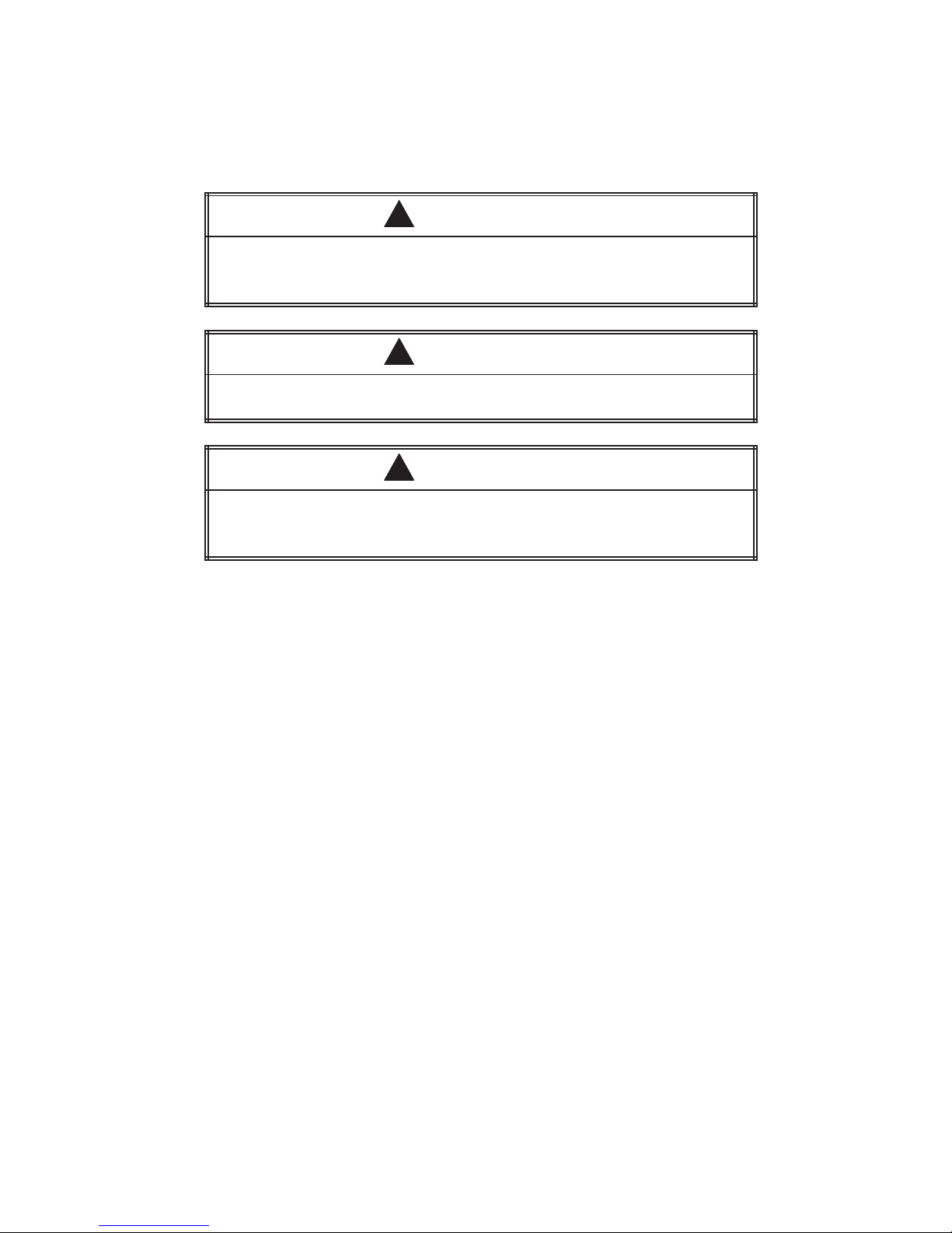
DANGER
!
DANGER indicates an imminently hazardous situation that, if not avoided, will
result in death or serious injury .
DANGER is limited to the most extreme situations.
WARNING
!
WARNING indicates a potentially hazardous situation that, if not avoided, could
result in death or serious injury , and/or property damage.
CAUTION
!
CAUTION indicates a potentially hazardous situation that, if not avoided, could
result in minor or moderate injury , and/or damage to property.
CAUTION is also used for property-damage-only accidents.
Copyright 1999 by Siemens Energy & Automation, Inc.
Reproduction, transmission, or use of this document or contents is not permitted without express consent of
Siemens Energy & Automation, Inc. All rights, including rights created by patent grant or registration of a utility model or design, are
reserved.
Since Siemens Energy & Automation, Inc., does not possess full access to data concerning all of the uses and applications of
customer’s products, we do not assume responsibility either for customer product design or for any infringements of patents or rights
of others which may result from our assistance.
All Rights Reserved — Printed in USA
Page 3

MANUAL PUBLICATION HISTORY
SIMATIC 505/500 PROFIBUS-DP RBC User Manual
Order Manual Number: Not applicable; manual ships with RBC.
Refer to this history in all correspondence and/or discussion about this manual.
Event Date Description
Original Issue 03/96 Original Issue (2806091–0001)
Second Edition 06/99 Second Edition (2806091–0002)
Page 4

LIST OF EFFECTIVE PAGES
Pages Description Pages Description
Cover/Copyright Second Edition
History/Effective Pages Second Edition
1 — 28 Second Edition
Registration Second Edition
Page 5

Contents
1 Overview 2. . . . . . . . . . . . . . . . . . . . . . . . . . . . . . . . . . . . . . . . . . . . . . . . . . . . . . . . . . . . . . . . . . . . . . .
Features and Functions 2. . . . . . . . . . . . . . . . . . . . . . . . . . . . . . . . . . . . . . . . . . . . . . . . . . . . . . . . .
RBC Specifications 2. . . . . . . . . . . . . . . . . . . . . . . . . . . . . . . . . . . . . . . . . . . . . . . . . . . . . . . . . . . . . .
2 Setup and Installation 4. . . . . . . . . . . . . . . . . . . . . . . . . . . . . . . . . . . . . . . . . . . . . . . . . . . . . . . . . . .
RBC Placement in Base 4. . . . . . . . . . . . . . . . . . . . . . . . . . . . . . . . . . . . . . . . . . . . . . . . . . . . . . . . .
Installing and Removing the RBC 5. . . . . . . . . . . . . . . . . . . . . . . . . . . . . . . . . . . . . . . . . . . . . . . .
3 RBC Ports 6. . . . . . . . . . . . . . . . . . . . . . . . . . . . . . . . . . . . . . . . . . . . . . . . . . . . . . . . . . . . . . . . . . . . . . .
RS-232 Port 6. . . . . . . . . . . . . . . . . . . . . . . . . . . . . . . . . . . . . . . . . . . . . . . . . . . . . . . . . . . . . . . . . . . . .
PROFIBUS-DP Port 7. . . . . . . . . . . . . . . . . . . . . . . . . . . . . . . . . . . . . . . . . . . . . . . . . . . . . . . . . . . . . . .
4 Output State Selection on the RBC 8. . . . . . . . . . . . . . . . . . . . . . . . . . . . . . . . . . . . . . . . . . . . . . .
Selecting Output State (Off/Freeze) on the 505 RBC 8. . . . . . . . . . . . . . . . . . . . . . . . . . . . . .
Selecting Output State (Off/Freeze) on the 500 RBC 9. . . . . . . . . . . . . . . . . . . . . . . . . . . . . .
Determining Discrete Output State 10. . . . . . . . . . . . . . . . . . . . . . . . . . . . . . . . . . . . . . . . . . . . . .
Determining Analog Output State 10. . . . . . . . . . . . . . . . . . . . . . . . . . . . . . . . . . . . . . . . . . . . . . .
5 Dipswitch Options: Baud Rate, Station Address, Status Display Mode 11. . . . . . . . . . . . . . .
Dipswitch Options 11. . . . . . . . . . . . . . . . . . . . . . . . . . . . . . . . . . . . . . . . . . . . . . . . . . . . . . . . . . . . . .
Baud Rate for the RS-232 Port 13. . . . . . . . . . . . . . . . . . . . . . . . . . . . . . . . . . . . . . . . . . . . . . . . . . . .
Assigning the RBC Station Address 13. . . . . . . . . . . . . . . . . . . . . . . . . . . . . . . . . . . . . . . . . . . . . . .
Reset Pushbutton 16. . . . . . . . . . . . . . . . . . . . . . . . . . . . . . . . . . . . . . . . . . . . . . . . . . . . . . . . . . . . . . .
Resetting the RBC 16. . . . . . . . . . . . . . . . . . . . . . . . . . . . . . . . . . . . . . . . . . . . . . . . . . . . . . . . . . . . . . .
Status Display Mode 18. . . . . . . . . . . . . . . . . . . . . . . . . . . . . . . . . . . . . . . . . . . . . . . . . . . . . . . . . . . .
6 Parameters Set by Software 20. . . . . . . . . . . . . . . . . . . . . . . . . . . . . . . . . . . . . . . . . . . . . . . . . . . . .
Setting User Parameters for the PROFIBUS-DP RBC 20. . . . . . . . . . . . . . . . . . . . . . . . . . . . . . . . .
Discrete I/O Interval 20. . . . . . . . . . . . . . . . . . . . . . . . . . . . . . . . . . . . . . . . . . . . . . . . . . . . . . . . . . . . .
Word I/O Update Factor 20. . . . . . . . . . . . . . . . . . . . . . . . . . . . . . . . . . . . . . . . . . . . . . . . . . . . . . . .
50X Ignore Mismatch Mode 20. . . . . . . . . . . . . . . . . . . . . . . . . . . . . . . . . . . . . . . . . . . . . . . . . . . . .
50X RS-232 Comm Port 20. . . . . . . . . . . . . . . . . . . . . . . . . . . . . . . . . . . . . . . . . . . . . . . . . . . . . . . . . .
7 Diagnostic Data Reported by the RBC 21. . . . . . . . . . . . . . . . . . . . . . . . . . . . . . . . . . . . . . . . . . . .
PROFIBUS-DP Diagnostic Bytes 21. . . . . . . . . . . . . . . . . . . . . . . . . . . . . . . . . . . . . . . . . . . . . . . . . . .
8 Upgrading the Operating System 26. . . . . . . . . . . . . . . . . . . . . . . . . . . . . . . . . . . . . . . . . . . . . . . .
Overview 26. . . . . . . . . . . . . . . . . . . . . . . . . . . . . . . . . . . . . . . . . . . . . . . . . . . . . . . . . . . . . . . . . . . . . . .
Download Instructions 27. . . . . . . . . . . . . . . . . . . . . . . . . . . . . . . . . . . . . . . . . . . . . . . . . . . . . . . . . .
Technical Assistance 28. . . . . . . . . . . . . . . . . . . . . . . . . . . . . . . . . . . . . . . . . . . . . . . . . . . . . . . . . . . .
SIMATIC 505/500 PROFIBUS-DP RBC User Manual
1
Page 6

1 Overview
Features and
Functions
The SIMATICr 505 PROFIBUS-DP Remote Base Controller (RBC),
PPX:505–6870, allows a Series 505t I/O base to function as a slave node on
a DP I/O channel that complies with the PROFIBUS standard (DIN 19245,
Part 3). The SIMATIC 500 PROFIBUS-DP Remote Base Controller (RBC),
PPX:500–6870, allows a Series 500t I/O base to function as a slave node on
a DP I/O channel that complies with the PROFIBUS standard.
The 505 and 500 PROFIBUS-DP RBCs offer the following features:
• The RBC is compatible with Siemens S5t and S7t, as well as Series
505, masters.
• The 505 RBC can be used in all currently-available Series 505 bases
(4-, 8-, 11-, and 16-slot models).
• The 500 RBC can be used in all Series 500 bases (6-, 12-, and 14-slot
models, or original 8- and 16-slot models with PPX:500–5840 adapter).
• The RBC supports communication speeds from 9.6 Kbaud (maximum
cable distance per segment: 1200 m) up to 12 Mbaud (maximum cable
distance per segment: 100 m).
• The LED display shows error codes or current station address.
• A serial port is available for remote programming of the CPU when the
RBC is used on a Series 505/500 system.
RBC Specifications
• The RBC has a field-upgradeable operating system that is stored in
flash memory.
• The base where the RBC resides can contain only modules that look
like discrete or analog I/O; Special Function modules like Peerlink or
NIMs are not supported.
• CPU commands received from the serial port are restricted to those
that cannot alter the PROFIBUS-DP I/O configuration.
• A “GSD” file is provided with the RBC to allow configuration by the
COM PROFIBUS configuration utility.
Figure 1 illustrates how the 505 and 500 PROFIBUS-DP RBCs fit into the
I/O architecture of a Series 505 system.
The physical and environmental specifications for the 505 PROFIBUS-DP
RBC are listed in the SIMATIC 545/555/575 System Manual.
2
SIMATIC 505/500 PROFIBUS-DP RBC User Manual
Page 7
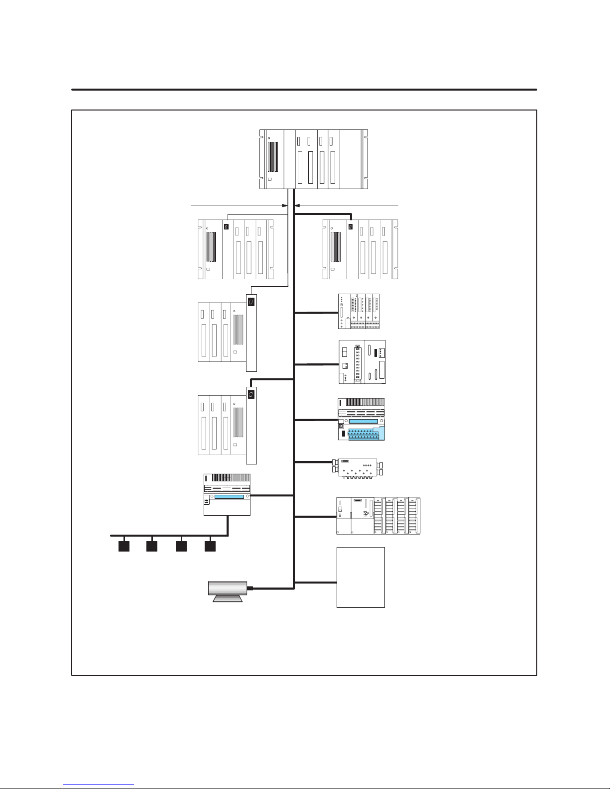
545/555/575
C
C
P
U
Series 505 Remote
I/O Channel
(1 Mbaud)
Series 505 Base with RBC
(PPX:505–6851–A/B RBC)
Series 500 Base with RBC
(PPX:500–51 14–A RBC)
Series 500 Base with 500
PROFIBUS-DP RBC
(PPX:500–6870 RBC)
PROFIBUS-DP
I/O Channel
(12 Mbaud)
R
B
C
R
B
C
R
Series 505 Base with
505 PROFIBUS-DP RBC
(PPX:505–6870 RBC)
ET200U
B
C
95U/PROFIBUS-DP
R
B
C
ET200B
Block I/O
ET200C
AS-Interface Master
S7 I/O
AS-Interface Bus
Allen-Bradley
Limit SW P/B Solenoid PE Cell
Siemens AC/DC
Motors and Drives
Festo
Metlore-Toledo
Data Logic
ABB
AEG-Modicon
Bosch
Turk
etc.
Third Party
Products
Notes:
The Series 505 remote I/O channel supports up to 15 Series 505/Series 500 remote bases.
The PROFIBUS-DP I/O channel supports up to 112 SIMATIC and third-party DP I/O slaves.
A 575–2104 CPU can support either the 505 I/O channel or the PROFIBUS-DP channel, but not both simultaneously.
The 545–1 103/–1105 CPUs support only the PROFIBUS-DP channel, up to 32 SIMATIC and third-party DP I/O slaves, with the
optional PROFIBUS-DP I/O annex card.
Figure 1 I/O Architecture for Series 505 System
SIMATIC 505/500 PROFIBUS-DP RBC User Manual
3
Page 8
2 Setup and Installation
RBC Placement in
Base
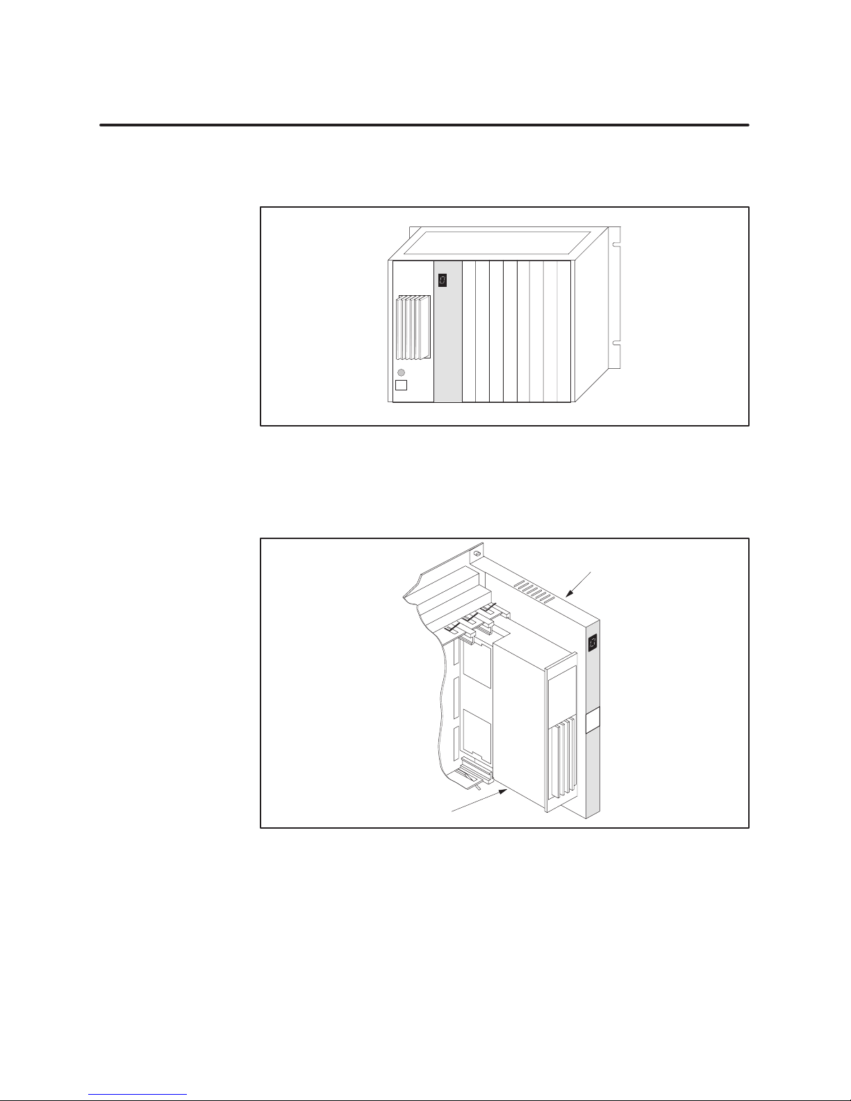
The 505 PROFIBUS-DP RBC resides in a Series 505 base. Install it in the
second slot from the left, adjacent to the power supply module. See Figure 2.
P/S
I
I
I
I
I
I
I
505
RBC
I
/
/
/
/
O
O
O
O
O
/
/
/
/
O
O
O
Figure 2 Location of RBC in a Series 505 Base
The 500 PROFIBUS-DP RBC resides in a Series 500 base. Install it in the
rightmost slot, adjacent to the power supply module. See Figure 3.
Series 500
Remote Base Controller
Power Supply
Figure 3 Location of RBC in a Series 500 Base
4
SIMATIC 505/500 PROFIBUS-DP RBC User Manual
Page 9
Installing and
Removing the RBC
Use the following steps to install the 505–6870 RBC in a Series 505 base or
to install the 500–6870 RBC in a Series 500 base.
WARNING
!
Installing or removing an RBC from a powered-up base disrupts your process
and can damage the RBC. Disruption of your process can cause death or
serious injury to personnel, and/or damage to equipment.
Ensure that all power is disabled before installing or removing the RBC.
CAUTION
!
The RBC is sensitive to, and can be damaged by , electrostatic discharge.
Ensure that personnel make contact with a static-dissipative pad and/or wear a
grounded wrist strap when handling the RBC.
1. Verify that all jumper settings on the 505 RBC or the Off/Freeze toggle
switch on the 500 RBC are correct. See Section 4. It is advisable to set
the dipswitch options before installing the module. See Section 5.
2. Disconnect power to the base.
3. Position the RBC so that the bezel is facing you.
4. Grasp the top and bottom of the RBC.
5. Carefully push the RBC into the slot until it mates with the backplane
connector.
6. Tighten the top and bottom bezel screws.
CAUTION
!
Series 505 RBCs are not designed to be installed in VME bases. Doing so
results in damage to equipment.
Never attempt to install any Series 505 RBC in a VME base.
To remove the RBC, complete the following steps.
1. If attached, remove cables from the RBC.
2. Disconnect power to the base.
3. Loosen the top and bottom bezel screws.
4. Carefully pull the RBC from the base.
SIMATIC 505/500 PROFIBUS-DP RBC User Manual
5
Page 10
3 RBC Ports
The 505 and 500 PROFIBUS-DP RBCs have two communication ports, an
RS-232 port and a PROFIBUS-DP I/O channel port.
RS-232 Port
When used with a Series 505 CPU, the RS-232 port is an interface to
programming devices that use software like TISOFT or other configuration
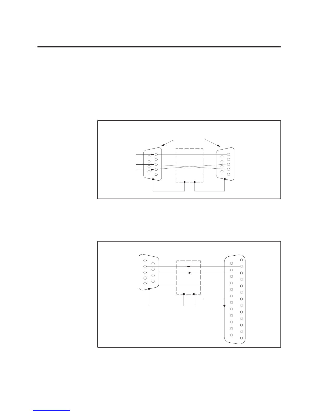
tools. To connect your RBC to a programming device/modem, use a standard
9-pin RS-232 serial cable that conforms at a minimum to the pinouts shown
in Figure 4. A standard cable that conforms to the minimum requirements
is available through Siemens; specify part number 2601094–8001.
Programming Device/Modem
Signal Ground (5)
Transmit Data (3)
Receive Data (2)
Pinouts
9
6
9-Pin, Female
D-Connector
5
3
2
1
Shield
RBC RS-232/423
Pinouts
5
9
6
Signal Ground
Transmit Data
3
Receive Data
2
1
Figure 4 RS-232 Serial Port, Minimum Cable Pinouts
Figure 5 shows the 25-pin cable connector pinouts required for the 25-pin
female communications port on the 500 RBC.
Programming Device/Modem
Pinouts
1
Receive Data
Transmit Data
Signal Ground
6
2
7
3
8
4
9
5
9-Pin, Female
D-Connector
Shield
Note: You can use the standard Siemens programming
cable (#2601094–8001) with a 9-to-25-pin male adapter.
RBC RS-232/423
Pinouts
1
14
2
15
3
16
4
17
5
18
6
19
7
20
8
21
9
22
10
23
11
24
12
25
13
Transmit Data
Receive Data
Signal Ground
25-Pin, Male
D-Connector
Figure 5 500 RBC RS-232 Serial Communications Cable Pinouts
6
SIMATIC 505/500 PROFIBUS-DP RBC User Manual
Page 11
PROFIBUS-DP Port
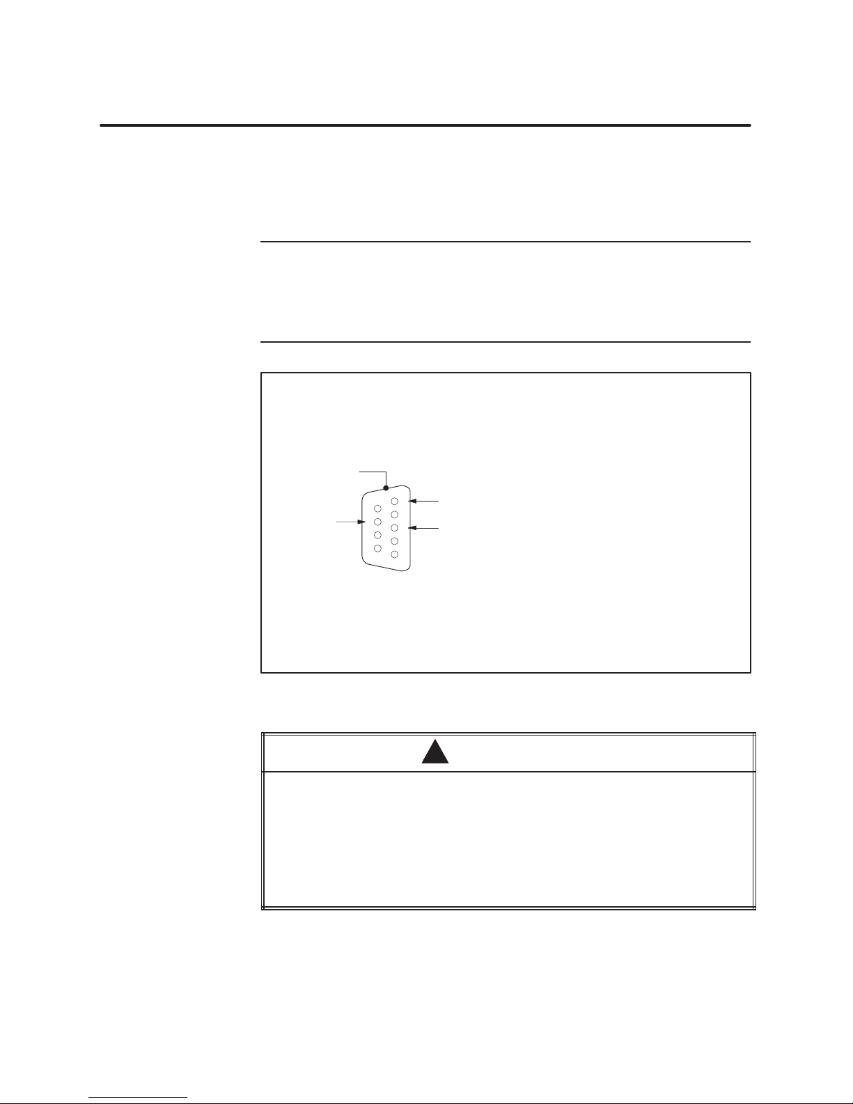
The PROFIBUS-DP port is used to connect the RBC to the PROFIBUS-DP
I/O channel. The SIMATIC 545/555/575 System Manual describes how to
connect a 12 Mbaud RS-485 cable to the PROFIBUS-DP port. Figure 6
shows the pinout for the PROFIBUS-DP port for the PROFIBUS-DP RBC.
NOTE: Pins 2 and 7 are “No Connect” for the RBC. For some PROFIBUS
products, these pins are used to provide 24 VDC for powering a
programming or configuration tool. Such tools are not powered by the RBC;
however, it is acceptable for an externally-powered PROFIBUS
programming or configuration tool to drive pins 2 and 7 to 24 VDC.
Female 9-Pin D-Connector
Pin Signal
CHASSIS GND
(D-shell)
CHASSIS GND
TX/RX– (8)
5
9
4
8
3
7
2
6
1
BIAS SUPPLY GND (5)
TX/RX+ (3)
1
2*3NO CONNECT
TX/RX+
4
RTS
BIAS SUPPLY GND
5
6
BIAS SUPPLY +5V
7 NO CONNECT
*8 TX/RX–
9
BIAS SUPPLY GND
Figure 6 PROFIBUS-DP I/O Port Pinouts
Pin 5 (BIAS SUPPLY +5V) and Pin 6 (BIAS SUPPLY GND) on the PROFIBUS-DP
connector are designed to support the PROFIBUS-DP I/O channel only. These
pins have a limited output power capability of approximately 0.45 W, which
greatly exceeds the typical PROFIBUS-DP load; however, overloading these
pins may cause internal component damage.
If the pins are overloaded, the PROFIBUS-DP port can be rendered
non-functional, requiring the unit to be returned to the factory for repair.
Do not overload the pins on the PROFIBUS-DP connector.
SIMATIC 505/500 PROFIBUS-DP RBC User Manual
CAUTION
!
* For Pin 3: Terminal B on Siemens connector.
* For Pin 8: Terminal A on Siemens connector.
7
Page 12
4 Output State Selection on the RBC
Selecting Output
State (Off/Freeze)
on the 505 RBC
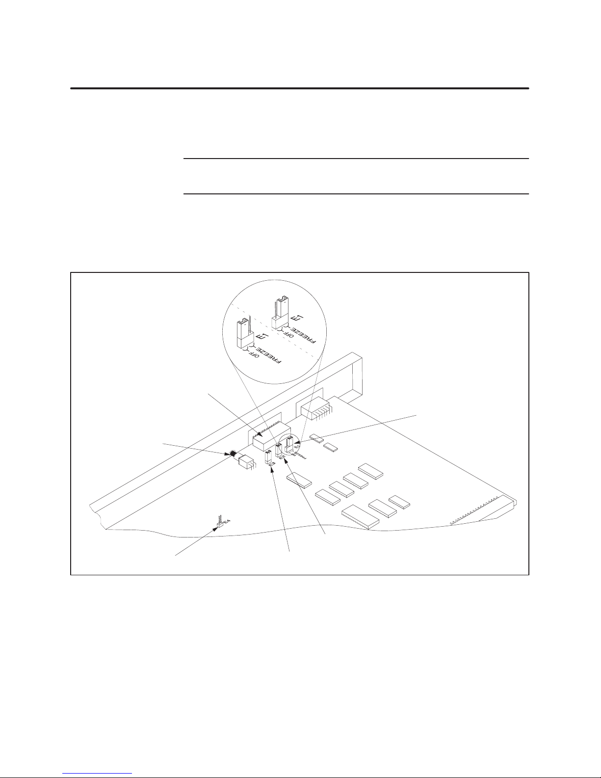
When I/O channel communication to a Series 505 base is lost, the state of
the outputs is determined by the selection made on the 505 RBC jumper E1
(Off/Freeze). Figure 7 shows the location of the jumpers on the 505 RBC.
NOTE: You must make an E1 jumper selection on the 505 RBC. The RBC
Status Display reports an error if no jumper selection is made.
The jumpers on the 505 RBC headers E2 and E3 are for factory use only.
Header E4 is shipped without a jumper. Do not alter the default settings
unless instructed to do so by a Siemens Technical Support technician.
Freeze
Outputs off
(default)
Dipswitch
Jumper E1 for
setting output state
(Off/Freeze)
RESET pushbutton
(recessed)
8
Header E4
Jumper E2
Jumper E3
Figure 7 505 RBC Jumper Locations
SIMATIC 505/500 PROFIBUS-DP RBC User Manual
Page 13
Selecting Output
State (Off/Freeze)
on the 500 RBC
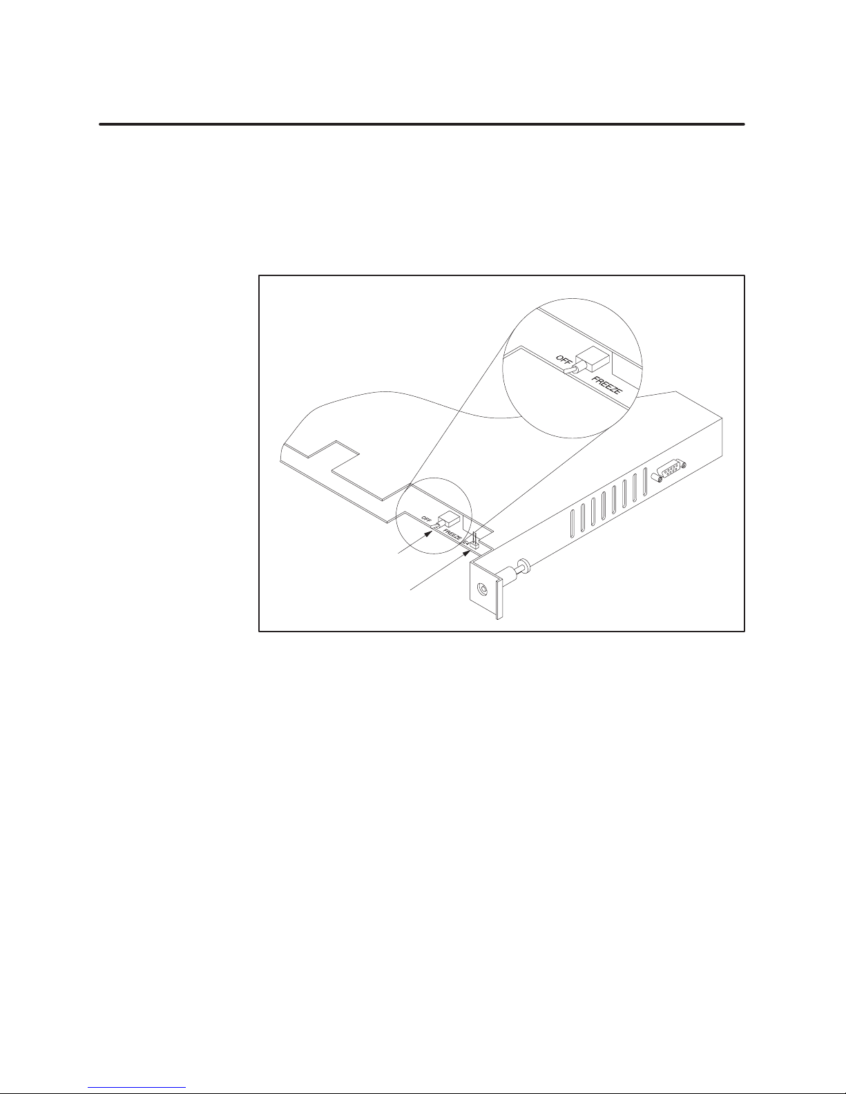
When I/O channel communication to a Series 500 base is lost, the state of
the outputs is determined by the position of the 500 RBC Off/Freeze toggle
switch. See Figure 8.
Header E4 is shipped without a jumper. Do not alter the default setting
unless instructed to do so by a Siemens Technical Support technician.
OFF
(factory set)
FREEZE
Output state (Off/Freeze) switch
Header E4
Figure 8 500 RBC Off/Freeze Switch
SIMATIC 505/500 PROFIBUS-DP RBC User Manual
9
Page 14
Output State Selection on the RBC (continued)
Determining
Discrete Output
State
Determining
Analog Output
State
For discrete output modules, the state of the outputs is determined solely by
the position of the Off/Freeze jumper E1 on the 505 RBC or the Off/Freeze
switch on the 500 RBC.
For analog/word output modules, the state of the outputs is influenced not
only by the position of the Off/Freeze switch but by the output module’s
(Zero/Hold Last Value) selection, if the module has that option. See Table 1.
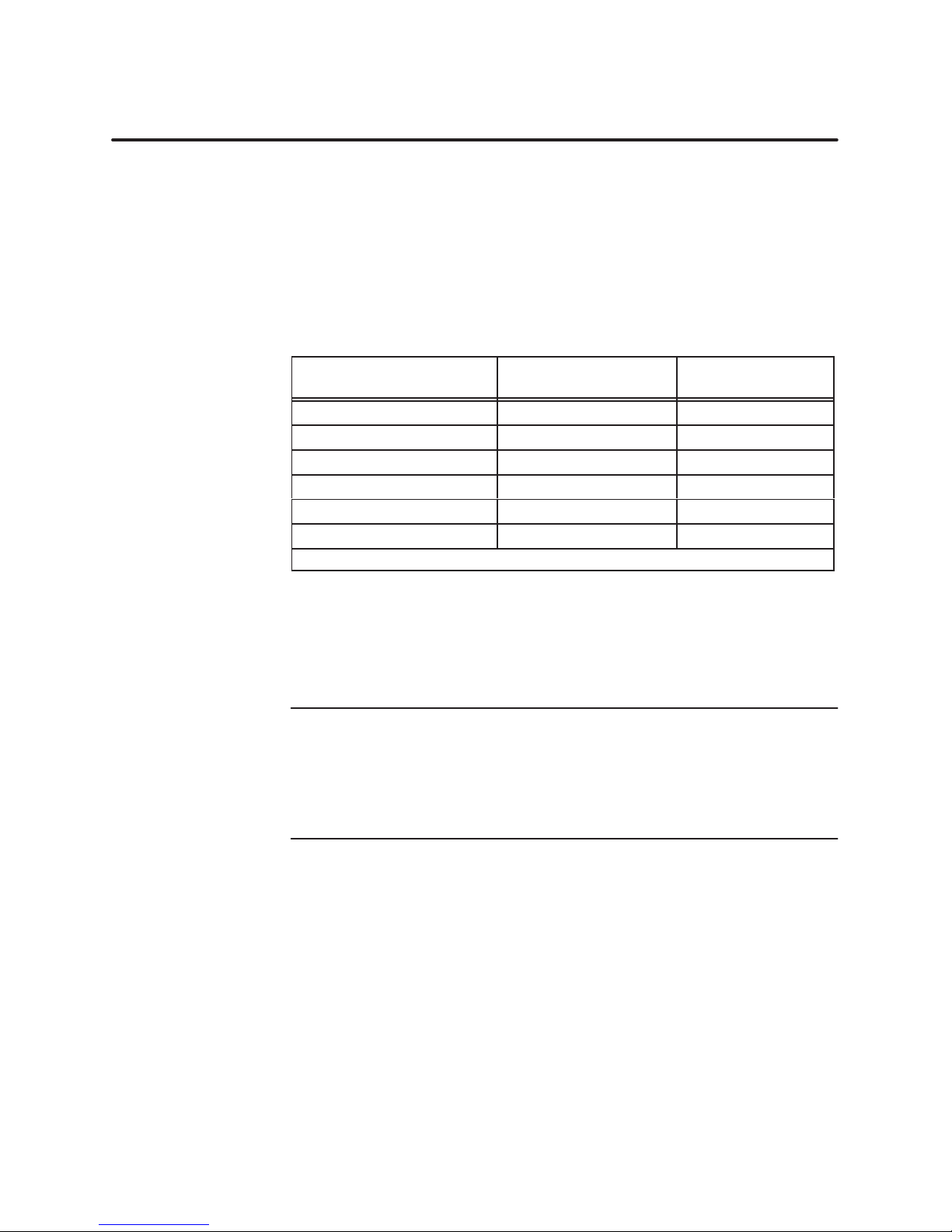
Table 1 Analog/Word Output States
RBC Off/Freeze Selection
Off Zero Zero*
Off Hold Last Value Last Value
Off – no selection – Last Value
Freeze Zero Last Value
Freeze Hold Last Value Last Value
Freeze – no selection – Last Value
*See the user manual of your analog/word output module for further details.
Analog/Word Module
Zero/Hold Selection
Analog/Word
Output State
Notice, in Table 1, that the Freeze option on the RBC overrides the Zero
selection on the analog/word output module; likewise, when Hold Last Value
is selected on the analog/word output module, that selection overrides the
Off option on the RBC jumper.
10
NOTE: If the RBC hardware watchdog timer is activated (by an RBC
failure), the state of the outputs is determined by the output module, with
no reference to the RBC’s Off/Freeze setting. Discrete outputs go off (to a
value of zero). Analog/word outputs obey their own Zero/Hold Last Value
selection. If no Zero/Hold Last Value selection is available on the module,
the analog/word outputs hold their last value.
SIMATIC 505/500 PROFIBUS-DP RBC User Manual
Page 15
5 Dipswitch Options: Baud Rate, Station Address, Status Display Mode
Dipswitch Options
Status display
Dipswitch
cover
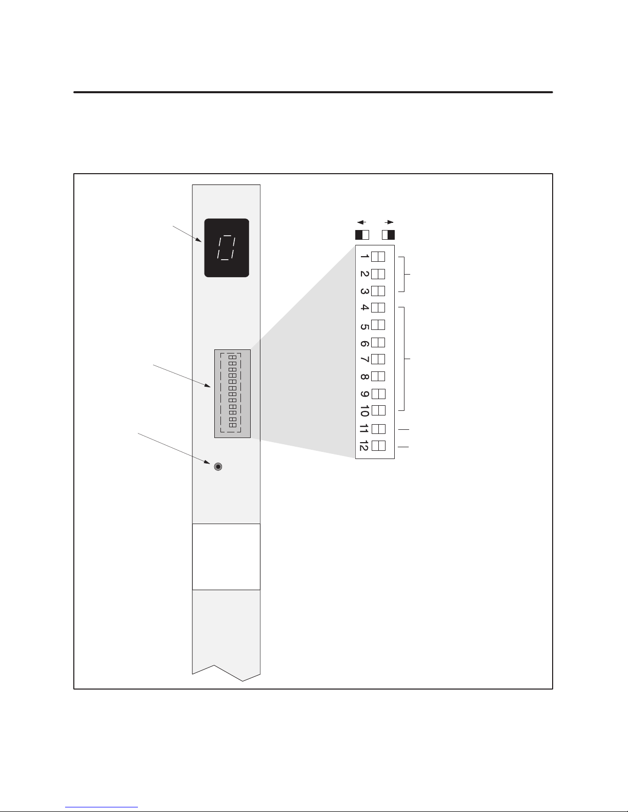
You can select the RS-232/423 baud rate, RBC station address, and display
mode of the RBC status display by setting a dipswitch that is accessible
from the bezel of the RBC. Figure 9 shows the location of the dipswitch and
dipswitch cover on the bezel of the 500 RBC.
MODEL
500-6870
STATUS
0–MODULE READY
1–DIAGNOSTIC FAILURE
2–MODULE MISMATCH
3–NO COMMUNICATIONS
4–NO OPERATIONAL FIRMWARE
5–NO HOLD MODE SELECTION
6–INVALID RS–232 BAUD RATE
7–NO I/O CONFIGURATION
8–WATCHDOG TIMER EXPIRED
C–SEE MANUAL
10
Set RS-232/423
Serial Port Baud Rate
See Table 2
Set RBC Station Address
See Table 3
RESET pushbutton
(recessed)
Set Status Display Mode
Spare
RESET
Dipswitch block
(located behind door)
Siemens
PROFIBUS
REMOTE
BASE
CONTROLLER
Figure 9 500 PROFIBUS-DP Remote Base Controller
SIMATIC 505/500 PROFIBUS-DP RBC User Manual
11
Page 16
Dipswitch Options (continued)
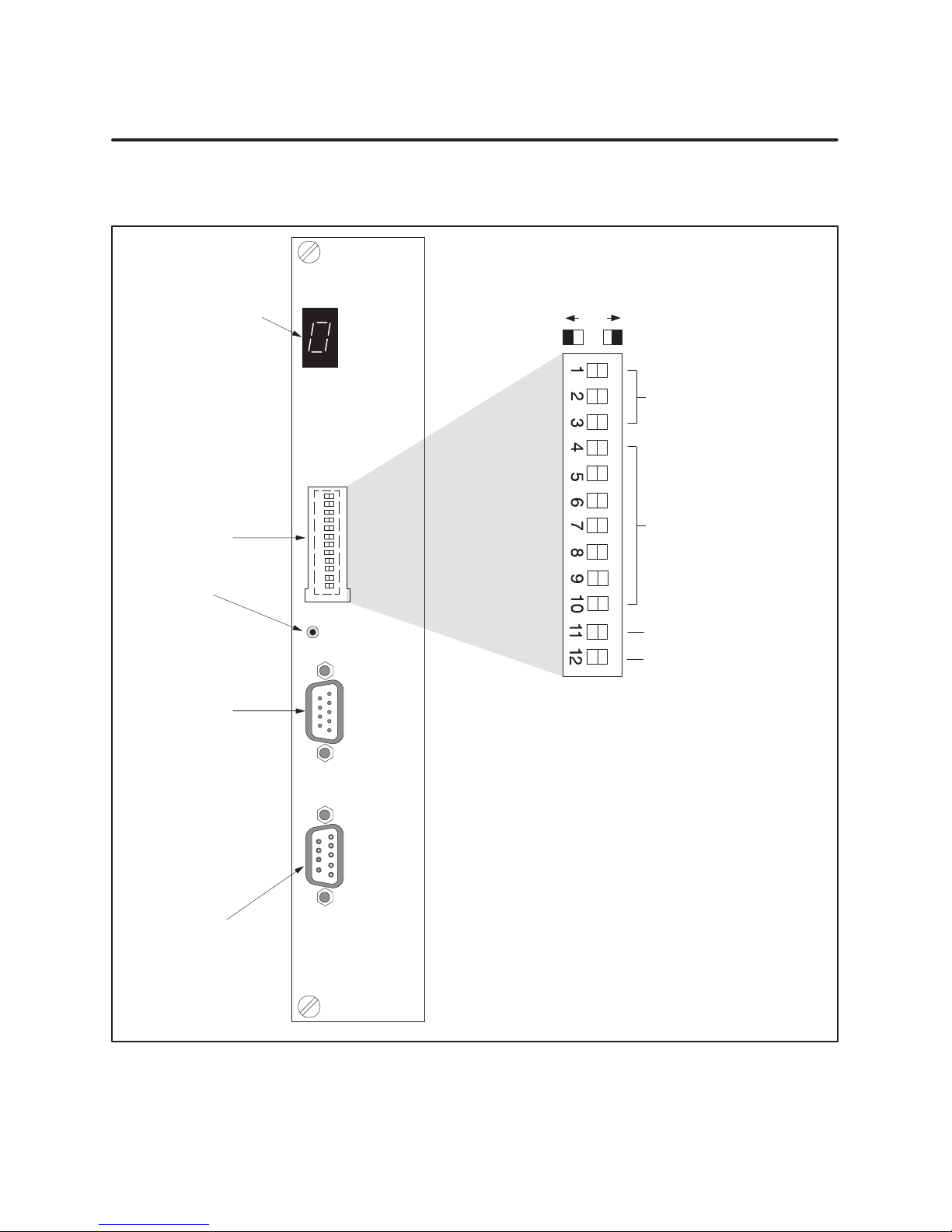
Figure 10 shows the location of the dipswitch and dipswitch cover on the
bezel of the 505 RBC.
505 PROFIBUS-DP
REMOTE BASE
Status display
CONTROLLER
STATUS
0–MODULE READY
1–DIAGNOSTIC FAILURE
2–MODULE MISMATCH
3–NO COMMUNICATIONS
4–NO OPERATIONAL FIRMWARE
5–NO HOLD MODE SELECTION
6–INVALID RS-232 BAUD RATE
7–NO I/O CONFIGURATION
8–WATCHDOG TIMER EXPIRED
C–SEE MANUAL
10
Set RS-232/423
Serial Port Baud Rate
See Table 2
Dipswitch
cover
RESET pushbutton
(recessed)
RS-232/423
serial port
(male)
I/O channel port
(female)
RESET
RS-232
PROFIBUS-DP
Set RBC Station Address
See Table 3
Set Status Display Mode
Spare
Dipswitch block
(located behind door)
505-6870
Figure 10 505 PROFIBUS-DP Remote Base Controller
12
SIMATIC 505/500 PROFIBUS-DP RBC User Manual
Page 17
Baud Rate for the
RS-232 Port
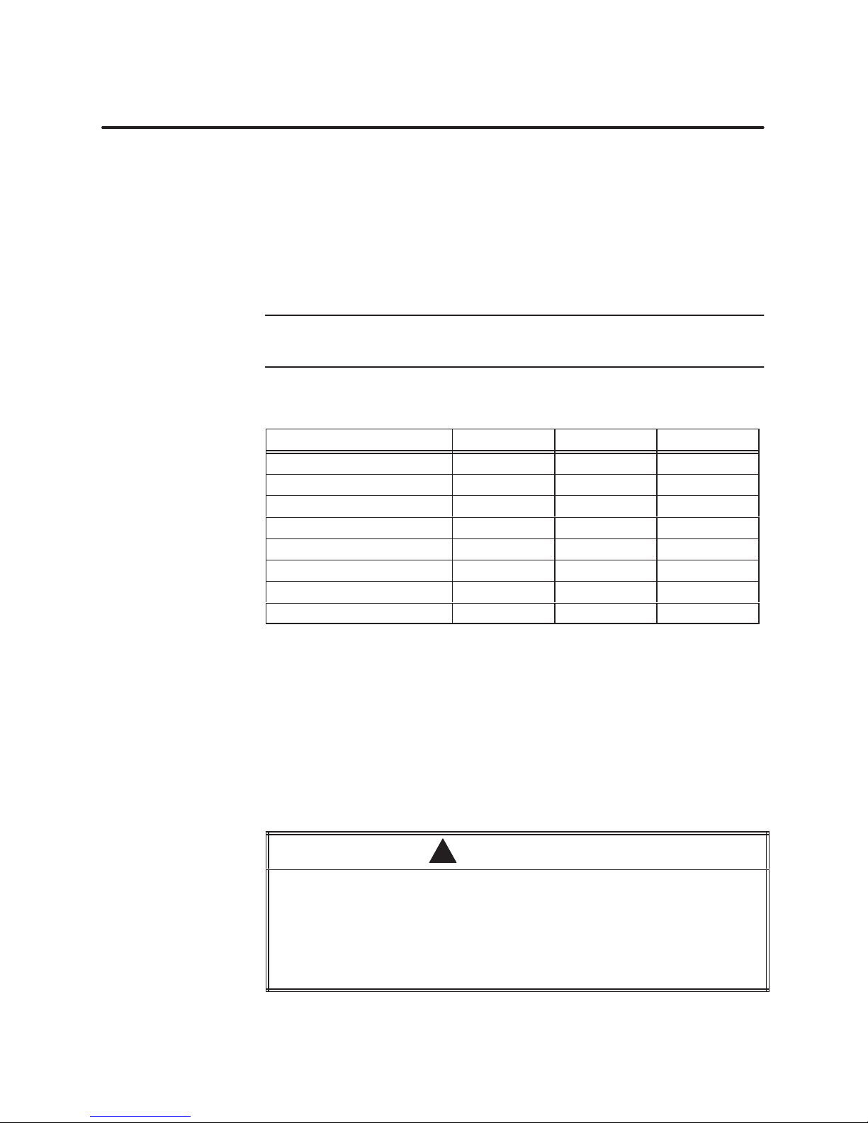
Switches 1 through 3 on the dipswitch control the baud rate of the
RS-232/423 port. Table 2 lists the baud rates available.
Invalid selections cause the RBC to report an error on the Status Display
and cause the RS-232/423 port to default to 9600 baud.
The RS-232/423 baud rate switch settings are read only on power-up or
after pressing the reset button.
NOTE: The RS-232 port is disabled by default. To enable the port, change
the default parameter of the module in COM PROFIBUS. (See Table 5.)
Table 2 RS-232 Port Baud Rate Settings
Baud Rate Switch 1 Switch 2 Switch 3
38400 0 0 1
19200 1 1 1
9600 1 1 0
2400 1 0 0
1200 0 1 0
300 0 0 0
INVALID 0 1 1
INVALID 1 0 1
Assigning the RBC
Station Address
Switches 4 through 10 on the dipswitch are used to assign a station address
to the RBC for identification in the PROFIBUS-DP I/O channel. Each
station in the PROFIBUS-DP I/O channel must be uniquely numbered. The
station address is assigned as a binary number, with SW10 as the Least
Significant Bit (LSB). Table 3 shows how to set the dipswitch to a station
address between 0 and 125 (the valid range of station addresses).
The station address switch settings are read only on power-up or after
pressing the reset button.
Pressing the RESET button when the system is operating causes the RBC to be
logged off the system and may change the output states of the output modules
in the base. Inadvertently logging the RBC off the system or changing output
states can cause unpredictable process operation.
Unpredictable process operation can result in death or serious injury to
personnel, and/or damage to equipment.
Do not push the reset button unless you intend to log the RBC off the system.
SIMATIC 505/500 PROFIBUS-DP RBC User Manual
WARNING
!
13
Page 18

Dipswitch Options (continued)
Table 3 Setting the RBC Station Address
Station
Station
Address
Sta. 0* 0 0 0 0 0 0 0 Sta. 33 0 1 0 0 0 0 1
Sta. 1 0 0 0 0 0 0 1 Sta. 34 0 1 0 0 0 1 0
Sta. 2 0 0 0 0 0 1 0 Sta. 35 0 1 0 0 0 1 1
Sta. 3 0 0 0 0 0 1 1 Sta. 36 0 1 0 0 1 0 0
Sta. 4 0 0 0 0 1 0 0 Sta. 37 0 1 0 0 1 0 1
Sta. 5 0 0 0 0 1 0 1 Sta. 38 0 1 0 0 1 1 0
Sta. 6 0 0 0 0 1 1 0 Sta. 39 0 1 0 0 1 1 1
Sta. 7 0 0 0 0 1 1 1 Sta. 40 0 1 0 1 0 0 0
Sta. 8 0 0 0 1 0 0 0 Sta. 41 0 1 0 1 0 0 1
Sta. 9 0 0 0 1 0 0 1 Sta. 42 0 1 0 1 0 1 0
Sta. 10 0 0 0 1 0 1 0 Sta. 43 0 1 0 1 0 1 1
Sta. 11 0 0 0 1 0 1 1 Sta. 44 0 1 0 1 1 0 0
Sta. 12 0 0 0 1 1 0 0 Sta. 45 0 1 0 1 1 0 1
Sta. 13 0 0 0 1 1 0 1 Sta. 46 0 1 0 1 1 1 0
Sta. 14 0 0 0 1 1 1 0 Sta. 47 0 1 0 1 1 1 1
Sta. 15 0 0 0 1 1 1 1 Sta. 48 0 1 1 0 0 0 0
Sta. 16 0 0 1 0 0 0 0 Sta. 49 0 1 1 0 0 0 1
Sta. 17 0 0 1 0 0 0 1 Sta. 50 0 1 1 0 0 1 0
Sta. 18 0 0 1 0 0 1 0 Sta. 51 0 1 1 0 0 1 1
Sta. 19 0 0 1 0 0 1 1 Sta. 52 0 1 1 0 1 0 0
Sta. 20 0 0 1 0 1 0 0 Sta. 53 0 1 1 0 1 0 1
Sta. 21 0 0 1 0 1 0 1 Sta. 54 0 1 1 0 1 1 0
Sta. 22 0 0 1 0 1 1 0 Sta. 55 0 1 1 0 1 1 1
Sta. 23 0 0 1 0 1 1 1 Sta. 56 0 1 1 1 0 0 0
Sta. 24 0 0 1 1 0 0 0 Sta. 57 0 1 1 1 0 0 1
Sta. 25 0 0 1 1 0 0 1 Sta. 58 0 1 1 1 0 1 0
Sta. 26 0 0 1 1 0 1 0 Sta. 59 0 1 1 1 0 1 1
Sta. 27 0 0 1 1 0 1 1 Sta. 60 0 1 1 1 1 0 0
Sta. 28 0 0 1 1 1 0 0 Sta. 61 0 1 1 1 1 0 1
Sta. 29 0 0 1 1 1 0 1 Sta. 62 0 1 1 1 1 1 0
Sta. 30 0 0 1 1 1 1 0 Sta. 63 0 1 1 1 1 1 1
Sta. 31 0 0 1 1 1 1 1 Sta. 64 1 0 0 0 0 0 0
Sta. 32 0 1 0 0 0 0 0 Sta. 65 1 0 0 0 0 0 1
*Address not allowed when connecting to 545/555/575 CPUs.
Switch Number/State
4 5 6 7 8 9 10
Station
Station
Address
Switch Number/State
4 5 6 7 8 9 10
14
SIMATIC 505/500 PROFIBUS-DP RBC User Manual
Page 19

Table 3 Setting the RBC Station Address (continued)
Station
Station
Address
Switch Number/State
4 5 6 7 8 9 10
Station
Station
Address
Switch Number/State
4 5 6 7 8 9 10
Sta. 66 1 0 0 0 0 1 0 Sta. 96 1 1 0 0 0 0 0
Sta. 67 1 0 0 0 0 1 1 Sta. 97 1 1 0 0 0 0 1
Sta. 68 1 0 0 0 1 0 0 Sta. 98 1 1 0 0 0 1 0
Sta. 69 1 0 0 0 1 0 1 Sta. 99 1 1 0 0 0 1 1
Sta. 70 1 0 0 0 1 1 0 Sta. 100 1 1 0 0 1 0 0
Sta. 71 1 0 0 0 1 1 1 Sta. 101 1 1 0 0 1 0 1
Sta. 72 1 0 0 1 0 0 0 Sta. 102 1 1 0 0 1 1 0
Sta. 73 1 0 0 1 0 0 1 Sta. 103 1 1 0 0 1 1 1
Sta. 74 1 0 0 1 0 1 0 Sta. 104 1 1 0 1 0 0 0
Sta. 75 1 0 0 1 0 1 1 Sta. 105 1 1 0 1 0 0 1
Sta. 76 1 0 0 1 1 0 0 Sta. 106 1 1 0 1 0 1 0
Sta. 77 1 0 0 1 1 0 1 Sta. 107 1 1 0 1 0 1 1
Sta. 78 1 0 0 1 1 1 0 Sta. 108 1 1 0 1 1 0 0
Sta. 79 1 0 0 1 1 1 1 Sta. 109 1 1 0 1 1 0 1
Sta. 80 1 0 1 0 0 0 0 Sta. 110 1 1 0 1 1 1 0
Sta. 81 1 0 1 0 0 0 1 Sta. 111 1 1 0 1 1 1 1
Sta. 82 1 0 1 0 0 1 0 Sta. 112 1 1 1 0 0 0 0
Sta. 83 1 0 1 0 0 1 1 Sta. 113* 1 1 1 0 0 0 1
Sta. 84 1 0 1 0 1 0 0 Sta. 114* 1 1 1 0 0 1 0
Sta. 85 1 0 1 0 1 0 1 Sta. 115* 1 1 1 0 0 1 1
Sta. 86 1 0 1 0 1 1 0 Sta. 116* 1 1 1 0 1 0 0
Sta. 87 1 0 1 0 1 1 1 Sta. 117* 1 1 1 0 1 0 1
Sta. 88 1 0 1 1 0 0 0 Sta. 118* 1 1 1 0 1 1 0
Sta. 89 1 0 1 1 0 0 1 Sta. 119* 1 1 1 0 1 1 1
Sta. 90 1 0 1 1 0 1 0 Sta. 120* 1 1 1 1 0 0 0
Sta. 91 1 0 1 1 0 1 1 Sta. 121* 1 1 1 1 0 0 1
Sta. 92 1 0 1 1 1 0 0 Sta. 122* 1 1 1 1 0 1 0
Sta. 93 1 0 1 1 1 0 1 Sta. 123* 1 1 1 1 0 1 1
Sta. 94 1 0 1 1 1 1 0 Sta. 124* 1 1 1 1 1 0 0
Sta. 95 1 0 1 1 1 1 1 Sta. 125* 1 1 1 1 1 0 1
*Address not allowed when connecting to 545/555/575 CPUs.
NOTE: It is possible to select Station Addresses 126 or 127 on the dipswitch, but these addresses are invalid.
SIMATIC 505/500 PROFIBUS-DP RBC User Manual
15
Page 20
Dipswitch Options (continued)
Reset Pushbutton
Resetting the RBC
The RESET pushbutton on the front of the RBC is deliberately recessed to
prevent accidental activation. When you press this button, a global reset is
immediately performed on the RBC. After completing reset, the RBC
assumes the RS-232 baud rate stipulated by the setting of switches 1
through 3 on the dipswitch, and the station address indicated by switches 4
through 10.
WARNING
!
Pressing the RESET button when the system is operating causes the RBC to be
logged off the system. When the RBC is logged off, inputs and outputs
associated with the base are affected. See the documentation for your system
master to find out how the master handles I/O when the RBC logs off. If you do
not take the condition of your inputs and outputs into account, logging the RBC
off the system can cause unpredictable process operation.
Unpredictable process operation can cause death or serious injury to
personnel, and/or damage to equipment.
Do not reset your RBC unless you understand and are prepared for the
consequences.
The following actions take place when an RBC is reset.
• The CPU logs the RBC off the system and sets the image register
points which represent the inputs from this RBC’s base to zero. The
image register is zeroed out until the RBC completes reset and resumes
communication with the CPU. If this occurs while the system is
operating, depending on your RLL program, turning these inputs off
could affect other base outputs.
16
• From the assertion of reset until the RBC completes the reset and
resumes communication with the CPU, the state of the outputs on this
RBC’s base is determined by the output module, with no reference to
the RBC’s Off/Freeze setting. Discrete outputs go off (to a value of zero).
Analog/word outputs obey their own Zero/Hold Last Value selection. If
no Zero/Hold Last Value selection is available on the module, the
analog/word outputs hold their last value.
• If the station address you assign to the RBC (by setting the dipswitch)
inadvertently duplicates an address already in use by another slave on
the I/O channel, then when the RBC completes its reset and attempts
to communicate, identifying itself with the new station address, the
other slave may be logged off the system. Intermittent operation could
occur as long as the two slaves are set to the same station address.
SIMATIC 505/500 PROFIBUS-DP RBC User Manual
Page 21

When the CPU logs an RBC off the system, it sets a corresponding bit in one
of the status words that are available to your RLL program. Your RLL
program can use these bits to detect the loss of the RBC and control the
outputs of other bases as appropriate for your application. For details about
status words and more information about programming, refer to the
SIMATIC 545/555/575 Programming Reference User Manual.
SIMATIC 505/500 PROFIBUS-DP RBC User Manual
17
Page 22
Dipswitch Options (continued)
Status Display
Mode
Switch 11 on the dipswitch controls the display mode of the RBC Status
Display to show either station address or module status.
• When switch 11 is set to 1, the station address of the RBC is displayed
as a three-digit number, one digit at a time. The display goes blank for
a short period of time between each digit and for a long period after the
last digit. For example, if the RBC station address is 18, it will be
displayed according to this pattern:
0 (short pause) → 1 (short pause) → 8 (long pause)
0 (short pause) → 1 (short pause) → 8 (long pause) . . .
The three-digit pattern repeats until the mode is changed.
• When switch 11 is set to 0, the status of the RBC is displayed,
according to the codes shown in Table 4.
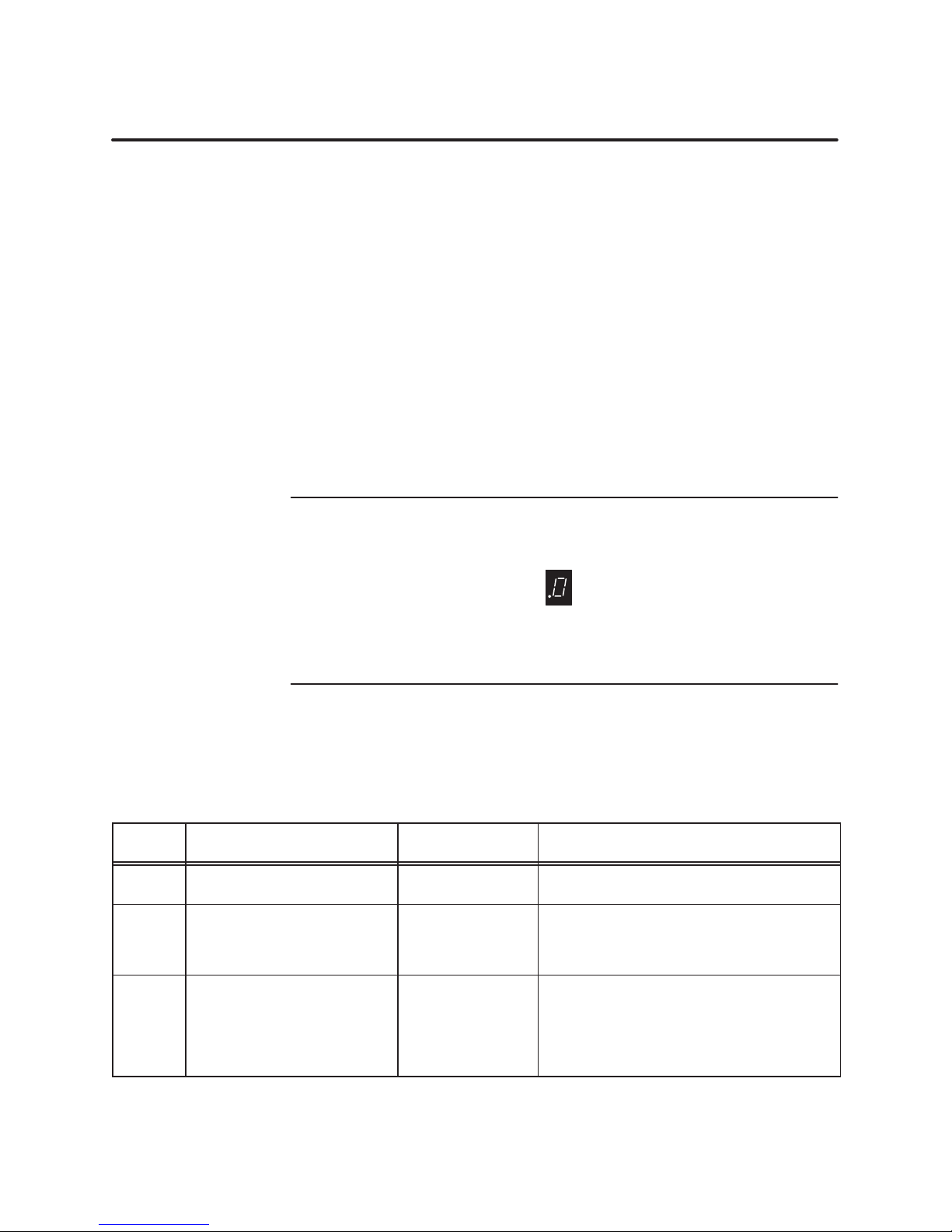
NOTE: When switch 11 is set to display the RBC status, a decimal point on
the status display indicates that the 50X Ignore Mismatch Mode parameter
is enabled. The point appears before the status code, as shown below.
If the 50X Ignore Mismatch Mode is disabled (the default value that
conforms to the DP standard), the RBC status display does not show a
decimal point. For more information about this parameter , see page 20.
The Status Display mode switch is read periodically during operation. The
switch may be changed at any time.
Table 4 PROFIBUS-DP RBC Status Codes
Display Definition
0 Module Ready OK
1 Diagnostic Failure None
2 Module Mismatch OK
Communications
to this RBC
Comment/Action
Fully operational. No errors detected.
Action: None.
Serious malfunction.
Action: Place the system in a safe state and
consult Siemens Technical Support. (In the
U.S.A., call 423–461–2522.)
I/O modules installed in this base do not
match the expected configuration in the
PROFIBUS-DP master.
Action: Compare the actual configuration of
the base against the configuration expected
by the PROFIBUS-DP master.
18
SIMATIC 505/500 PROFIBUS-DP RBC User Manual
Page 23

Table 4 PROFIBUS-DP RBC Status Codes (continued)
Display Definition
3 No Communications None
4 No Operational Firmware None
5 No Hold Mode Selection OK
6 Invalid RS-232/423 Baud Rate OK
7 No I/O Configuration Not Ready
8 Watchdog Timer Expired None
C
–blank– Blank, No Code Displayed None
Consult Siemens Technical
Support
Communications
to this RBC
Not Ready
Comment/Action
The RBC detects no PROFIBUS-DP I/O
channel activity.
Action: Place the system in a safe state and
check the connection to the PROFIBUS-DP
I/O channel. Ensure that other
PROFIBUS-DP I/O channel devices are
powered and not reporting errors.
Firmware is missing.
Action: Download new firmware into Flash
Memory.
[505 RBC only] Jumper E1 is missing or
not recognized.
Action: Install jumper on header E1.
Default: The RBC continues to operate with
a missing jumper; if communication is lost,
outputs will be driven to Off setting.
Improper dipswitch selection for RS-232
baud rate.
Action: Set the dipswitch to valid RS-232
baud rate.
Default: The RBC continues to operate with
an improper dipswitch setting; it uses an
RS-232 baud rate of 9600.
PROFIBUS-DP master and RBC did not
complete I/O channel initialization.
Probable causes: The station address is
incorrect, or the I/O modules installed in
this base do not match the I/O configuration
expected by the PROFIBUS-DP master.
Action: Check for and if necessary select a
valid station address. Compare the actual
configuration of the base against the
configuration expected by the
PROFIBUS-DP master.
Hardware watchdog timeout that
immediately resets the RBC.
Action: Serious malfunction. Place the
system in a safe state and consult Siemens
Technical Support. (In the U.S.A., call
423–461–2522.)
Serious malfunction.
Action: Place the system in a safe state and
consult Siemens Technical Support. (In the
U.S.A., call 423–461–2522.)
No power to base, or serious malfunction.
Action: Check power to base. If base power is
OK, place the system in a safe state and
consult Siemens Technical Support. (In the
U.S.A., call 423–461–2522.)
SIMATIC 505/500 PROFIBUS-DP RBC User Manual
19
Page 24

6 Parameters Set by Software
Setting User
Parameters for the
PROFIBUS-DP RBC
The PROFIBUS-DP RBC has parameters that are specified using the
COM PROFIBUS configuration utility software. Refer to the SIMATIC 505
TISOFT2 User Manual and the SIMATIC S5 ET 200 Distributed I/O
System Manual for information about using COM PROFIBUS.
Table 5 describes the parameters used to set up the 505/500 PROFIBUS-DP
RBC in COM PROFIBUS. You set these parameters by selecting the
“Parameterize” dialog box in COM PROFIBUS.
Table 5 PROFIBUS-DP RBC Software Parameters
Parameter Valid Values Default Value Comment
Discrete I/O
Interval
Word I/O
Update Factor
50X Ignore
Mismatch
Mode
50X RS-232
Comm Port
1–255 msec 1 The RBC updates discrete I/O modules at this rate.
1–255 2
Disable/Enable Disable
Disable/Enable Disable Disable or enable RS-232 port communications.
Determines the number of discrete I/O updates performed
per I/O word update.
Disable: specifies DP Standard configuration mismatch
handling.
Enable: specifies Series 50X configuration mismatch
handling.
Discrete I/O
Interval
Word I/O Update
Factor
50X Ignore
Mismatch Mode
50X RS-232 Comm
Port
The Discrete I/O Interval parameter defines the rate at which the
PROFIBUS-DP RBC updates I/O modules. This parameter specifies the
minimum time between updates of the discrete I/O modules.
The Word I/O Update Factor controls how often the word I/O modules are
updated. The Word I/O Factor is the number of discrete I/O updates
performed per word update; for example, if the factor is 2, the word I/O
modules are updated on every second discrete I/O update.
The 50X Ignore Mismatch Mode parameter allows you to select the way I/O
configuration mismatches are handled. With the default setting, “Disable,”
the PROFIBUS-DP RBC handles I/O configuration mismatches according to
DP Standard mode, meaning that the configuration sent by the CPU to the
RBC must match the actual base configuration exactly, or else no I/O
updates are performed. If you enable 50X Ignore Mismatch Mode, the RBC
performs updates with all modules whose configuration matches, omitting
only those modules whose configuration does not match. This mode of
operation does not conform to the DP Standard.
The default for RS-232 port communications is communications disabled.
When 50X RS-232 Comm Port is enabled, the RBC is not operating in 100%
compliance with the PROFIBUS-DP Standard due to the additional network
traffic caused by task code transfers.
20
SIMATIC 505/500 PROFIBUS-DP RBC User Manual
Page 25
7 Diagnostic Data Reported by the RBC
PROFIBUS-DP
Diagnostic Bytes
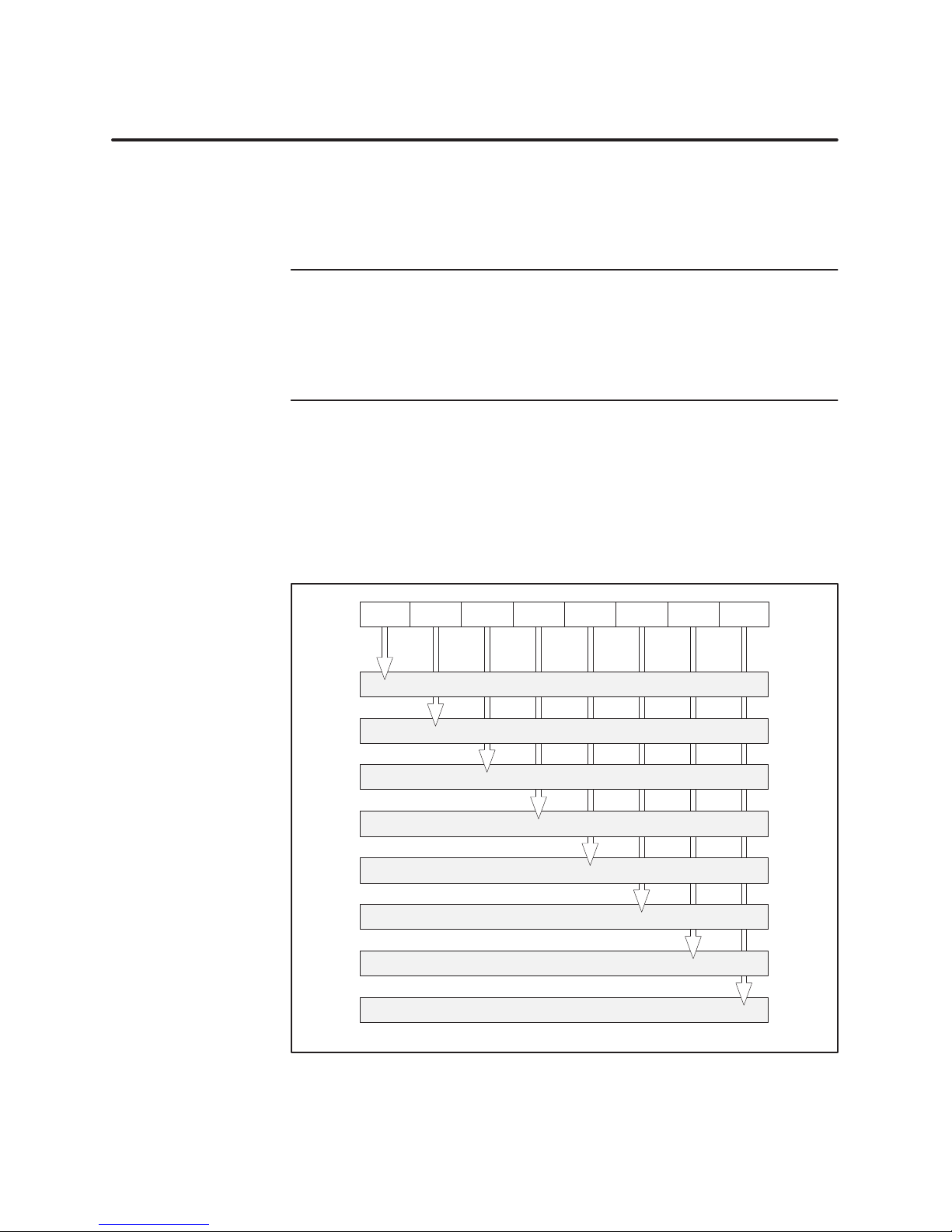
Byte 1:
Station_Status_1
The standard for PROFIBUS-DP I/O, DIN 19245, Part 3, stipulates the
format that each DP slave shall use to report specific diagnostics to the DP
master. The diagnostics used by the 505/500 PROFIBUS-DP RBCs are
described below.
NOTE: Byte 1 through Byte 15, as described in this text, correspond to
Octet 1 through Octet 15 in the PROFIBUS standard. For PROFIBUS-DP
I/O, Bit 7 is the most significant bit (MSB), 0 is the least significant bit
(LSB). This may or may not correspond to the bit numbering scheme used in
your master system. For example, Series 505/500 controllers identify the
MSB of a byte as Bit 1, and the LSB of a byte as Bit 8.
A DP diagnostic consists of two parts. The first part (Bytes 1 through 6) is
standardized for all DP slaves. The second, or extended, part (Bytes 7
through 15 in the case of the RBC) is slave-specific. In the description that
follows, it is assumed that the diagnostic has been successfully read from an
RBC that has been configured and activated: that is, that Bytes 5 and 6
equal 0xBC and 0xD0, respectively.
MSB LSB
01234567
7
RBC parameterized from another master (see description of Byte 4)
6
Parameterization error
5
Invalid response from RBC (always set to 0)
4
Unsupported function requested from the RBC
3
Extended diagnostics (Bytes 7–15) present
2
Configuration error
1
RBC not ready
0
RBC did not respond
Note: If Bit 0 is set to 1 then the value of Bit 3 will be 0. Otherwise, the value of Bit 3 is 1.
SIMATIC 505/500 PROFIBUS-DP RBC User Manual
21
Page 26
Diagnostic Data Reported by the RBC (continued)
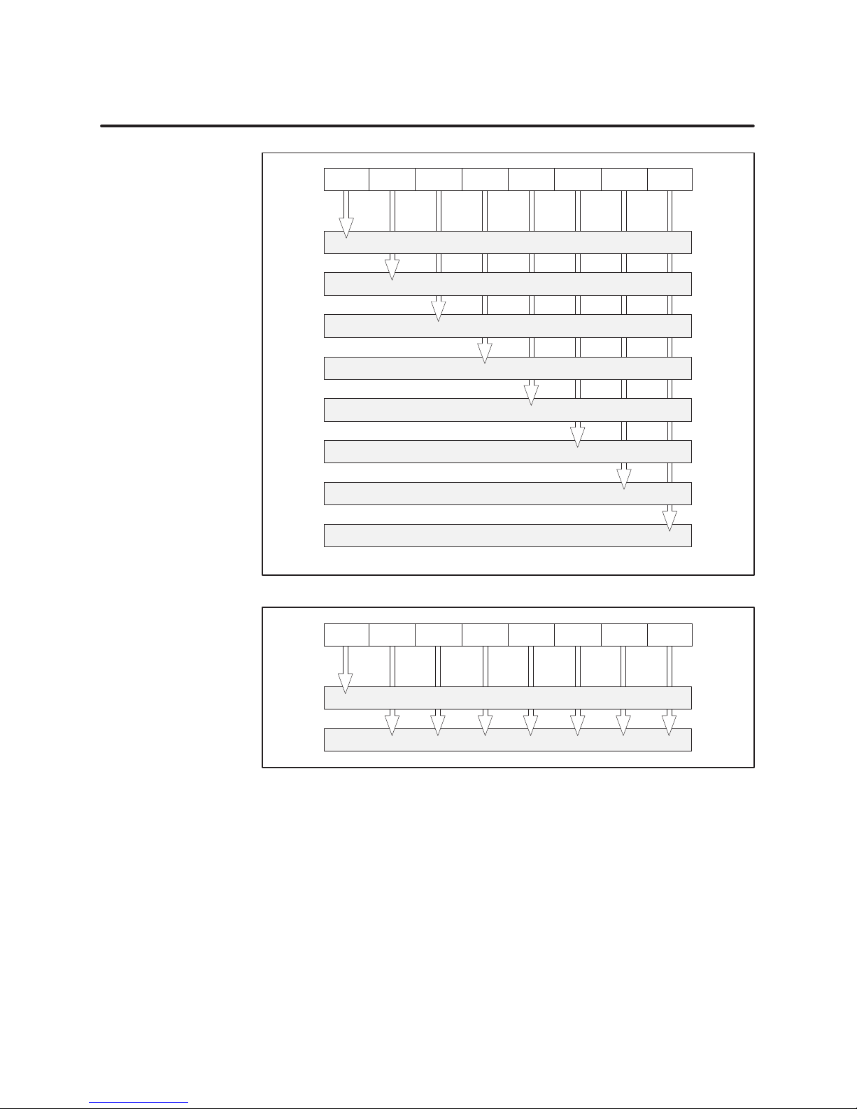
Byte 2:
Station_Status_2
MSB LSB
01234567
7
RBC is configured but not active (RBC can only set this to 0)
6
Reserved
5
RBC is operating in SYNCHRONOUS mode
4
RBC is operating in FREEZE mode
3
RBC’s watchdog timer has been activated
2
Always set to 1
1
Static diagnostics (always set to 0)
0
RBC waiting for parameterization
Byte 3:
Station_Status_3
Byte 4:
Diag.Master_Add
Bytes 5–6:
Ident_Number
Byte 7:
Ext_Diag_Data
Note: If Bit 1 and Bit 0 are set, Bit 0 has the higher priority.
MSB LSB
01234567
7
Diagnostic overflow (always set to 0)
6
Reserved
5 4 3 2 1 0
Bits 7–0 contain the address of the master that has parameterized the RBC.
If none of the DP masters has parameterized the RBC, then the RBC inserts
the address 255 in this byte.
Manufacturer identifier for the 505/500 PROFIBUS-DP RBC; values are
0xBC and 0xD0, respectively.
Device-related diagnostic header; value is 0x06.
22
SIMATIC 505/500 PROFIBUS-DP RBC User Manual
Page 27
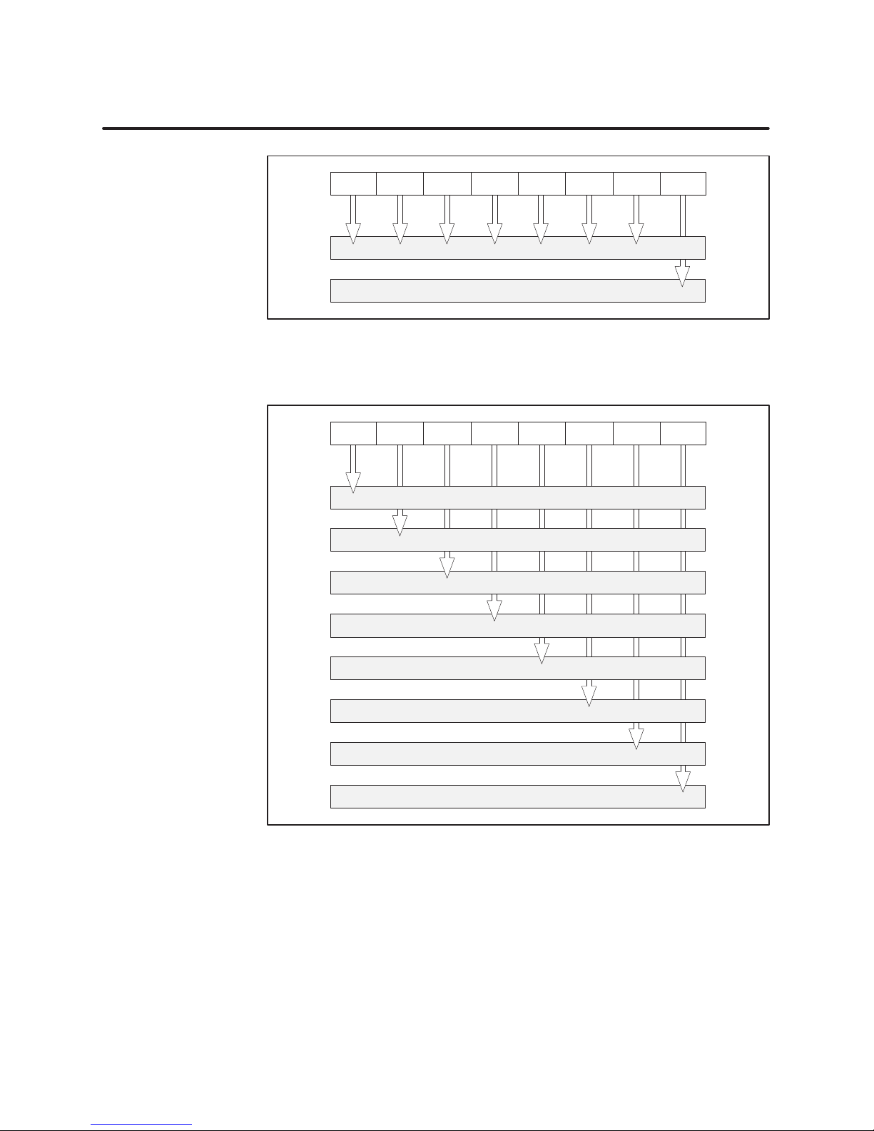
Byte 8:
Ext_Diag_Data
MSB LSB
01234567
Bytes 9–10:
Ext_Diag_Data
Byte 11:
Ext_Diag_Data
Reserved.
7
65
4
32
1
Reserved
0
Remote port request pending
MSB LSB
01234567
7
Slot 8 is mismatched type
6
Slot 7 is mismatched type
5
Slot 6 is mismatched type
4
Slot 5 is mismatched type
3
Slot 4 is mismatched type
2
Slot 3 is mismatched type
1
Slot 2 is mismatched type
0
Slot 1 is mismatched type
SIMATIC 505/500 PROFIBUS-DP RBC User Manual
23
Page 28
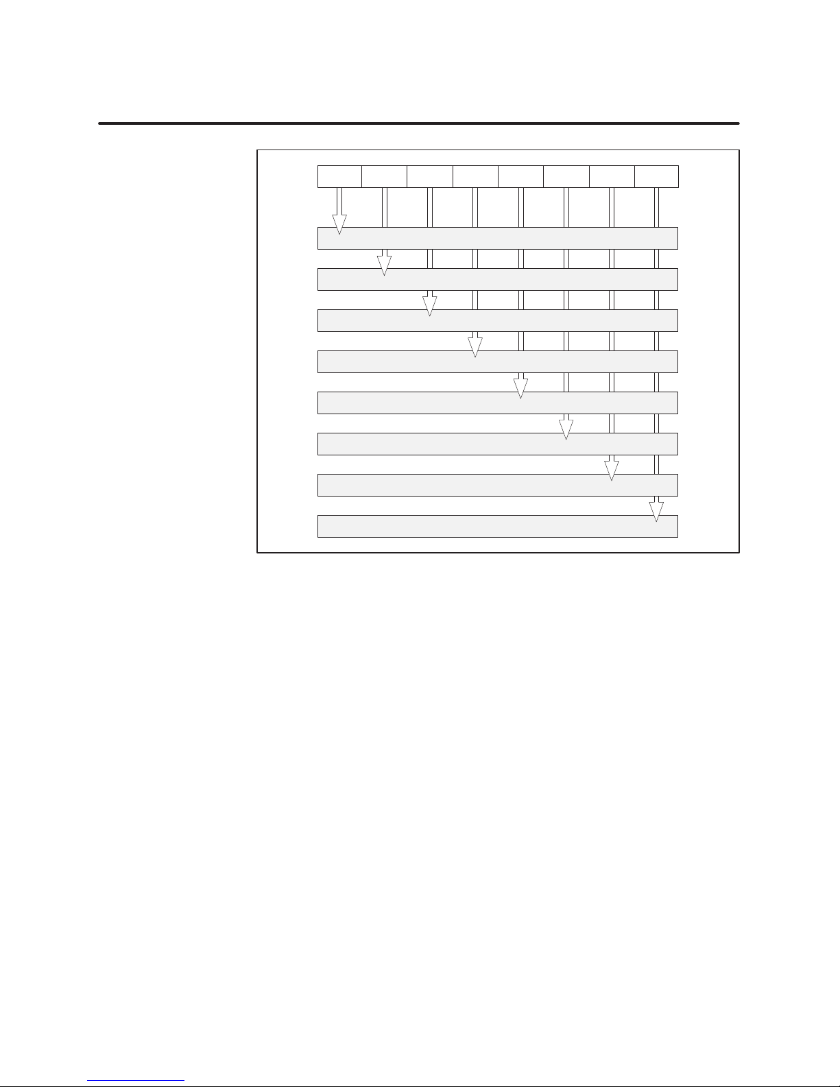
Diagnostic Data Reported by the RBC (continued)
Byte 12:
Ext_Diag_Data
MSB LSB
01234567
7
Slot 16 is mismatched type
6
Slot 15 is mismatched type
5
Slot 14 is mismatched type
4
Slot 13 is mismatched type
3
Slot 12 is mismatched type
2
Slot 11 is mismatched type
1
Slot 10 is mismatched type
0
Slot 9 is mismatched type
Byte 13:
Ext_Diag_Data
Identifier-related diagnostic header; value is 0x43.
24
SIMATIC 505/500 PROFIBUS-DP RBC User Manual
Page 29
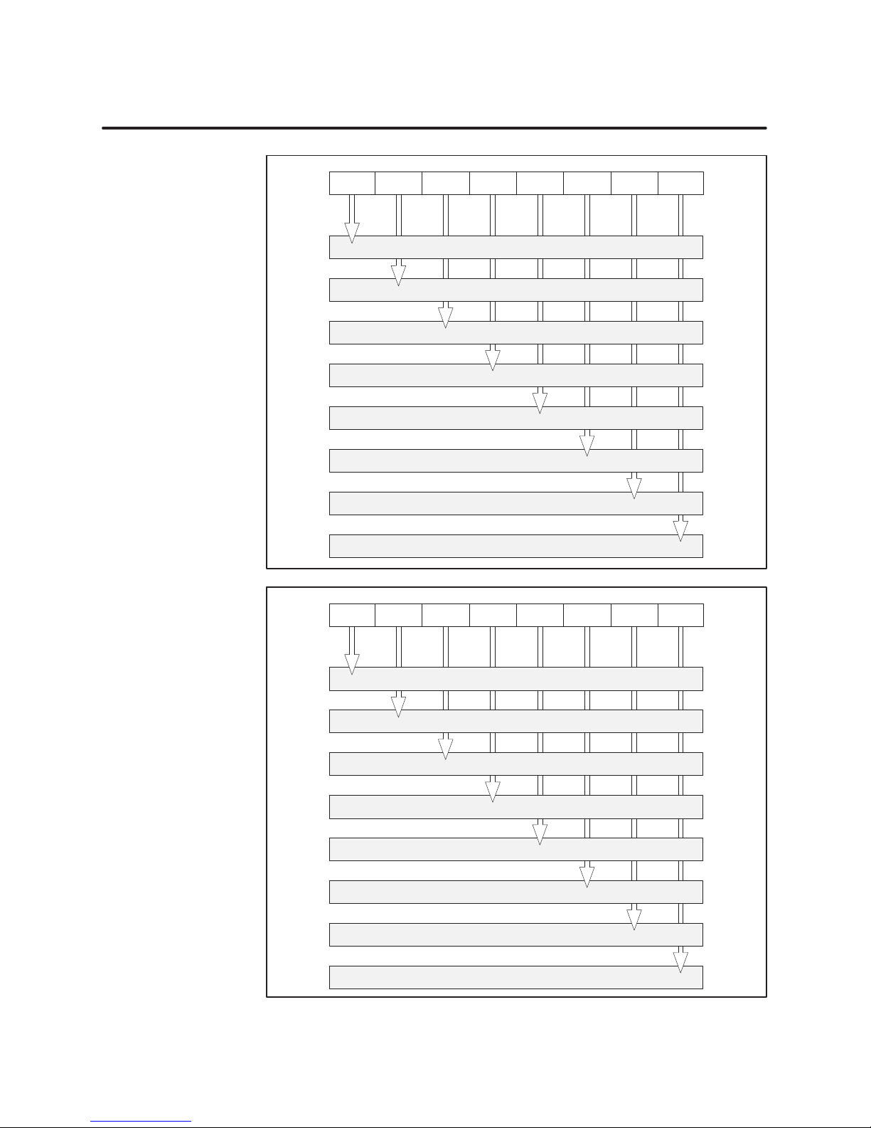
Byte 14:
Ext_Diag_Data
MSB LSB
01234567
7
Slot 8 contains failed module or is mismatched type
6
Slot 7 contains failed module or is mismatched type
5
Slot 6 contains failed module or is mismatched type
4
Slot 5 contains failed module or is mismatched type
3
Slot 4 contains failed module or is mismatched type
2
Slot 3 contains failed module or is mismatched type
1
Slot 2 contains failed module or is mismatched type
0
Slot 1 contains failed module or is mismatched type
Byte 15:
Ext_Diag_Data
MSB LSB
01234567
7
Slot 16 contains failed module or is mismatched type
6
Slot 15 contains failed module or is mismatched type
5
Slot 14 contains failed module or is mismatched type
4
Slot 13 contains failed module or is mismatched type
3
Slot 12 contains failed module or is mismatched type
2
Slot 11 contains failed module or is mismatched type
1
Slot 10 contains failed module or is mismatched type
0
Slot 9 contains failed module or is mismatched type
SIMATIC 505/500 PROFIBUS-DP RBC User Manual
25
Page 30

8 Upgrading the Operating System
Overview
The operating system of the 505/500 PROFIBUS-DP RBC is contained in
user-programmable non-volatile memory. An RBC with a previous release of
the operating system can be reprogrammed with the latest release. You
need a PC and a standard cable in order to reprogram the RBC.
Contact the Technical Services Group for the appropriate upgrade files if
you need to upgrade your RBC.
The operating system firmware for the RBC is supplied in a file called
DPRBC.DLD. You use the RBCDL.EXE program to download operating
system firmware from a binary file on the PC to the flash memory of the
RBC.
26
SIMATIC 505/500 PROFIBUS-DP RBC User Manual
Page 31

Download
Instructions
To download the new operating system firmware and locally program your
PROFIBUS-DP RBC, follow the steps below:
1. Ensure that your process is in a safe state before you begin to download
the new operating system firmware; I/O communication is temporarily
interrupted by the downloading procedure.
2. Connect your computer to the RBC with a standard 9-pin RS-232/423
null modem serial cable. This cable is available through your Siemens
Energy & Automation, Inc., distributor: ask for SIMATIC 545/555
Programming Cable, part number 2601094–8001.
3. Connect one end of the cable to the appropriate 9-pin RS-232/423 serial
port on your computer, and connect the other end to the RS-232 port on
the RBC. For the 500 RBC, use the same cable with a 9-to-25-pin male
adapter.
If your computer does not have a 9-pin port, use a 25-to-9-pin converter.
NOTE: If your AUTOEXEC.BAT or CONFIG.SYS files are programmed to
load a driver, such as a mouse driver, to the port that you wish to use,
communications with the RBC will not be successful. Be sure that neither
your AUTOEXEC.BA T nor your CONFIG.SYS file is programmed to load a
driver to the port.
4. Verify that the RBCDL.EXE file and the DPRBC.DLD file are in the
current MS-DOS directory. Make sure that the base that contains the
PROFIBUS-DP RBC is turned on.
5. At the MS-DOS prompt, type in the download command, specifying the
PC port number (namely, 1 or 2) that is appropriate for your PC
configuration, and then press Enter.
For example, if your port number is 2, type the following text:
RBCDL DPRBC.DLD 2
and then press
SIMATIC 505/500 PROFIBUS-DP RBC User Manual
Enter .
27
Page 32
Upgrading the Operating System (continued)
6. T wo information prompts appear. Answer Y to continue the download,
or
N to abort the download.
7. Immediately after you answer the second prompt with
Y, depress the
RBC reset pushbutton. This resets the RBC and begins the transfer to
the new operating system that you are downloading.
WARNING
!
Pressing the reset button when the system is operating causes the RBC to be
logged off the system and may change the output states of the output modules
in the base. Inadvertently logging the RBC off the system or changing output
states can cause unpredictable process operation.
Unpredictable process operation can cause death or serious injury to
personnel, and/or damage to equipment.
Do not reset your RBC unless you are prepared for the consequence of
disrupting I/O communication.
NOTE: The download of the operating system firmware takes approximately
2 minutes to complete. The RBC LED blinks, and Percent Complete displays
on the PC.
When the download is complete, the RBC automatically reboots itself and is
ready to communicate.
Technical
Assistance
28
For technical assistance, contact your Siemens Energy & Automation, Inc.,
distributor or sales office. If you need assistance in contacting your
distributor or sales office, call 800-964-4114 in the U.S.A.
For additional technical assistance, call the Siemens Technical Services
Group in Johnson City, Tennessee at 423-461-2522, or contact them by
e-mail at [email protected]. For technical assistance
outside the United States, call 49-911-895-7000.
You can also find information about Siemens automation products at our
website at http://www.aut.sea.siemens.com.
SIMATIC 505/500 PROFIBUS-DP RBC User Manual
Page 33

SIMA TIC is a registered trademark of Siemens AG.
S5 and S7 are trademarks of Siemens AG.
Series 505, Series 500, and TISOFT2 are trademarks of Siemens Energy & Automation, Incorporated.
MS-DOS is a registered trademark of Microsoft Corporation.
 Loading...