

Page 1
Page 2
___________________
___________________
___________________
___________________
___________
___________________
___________________
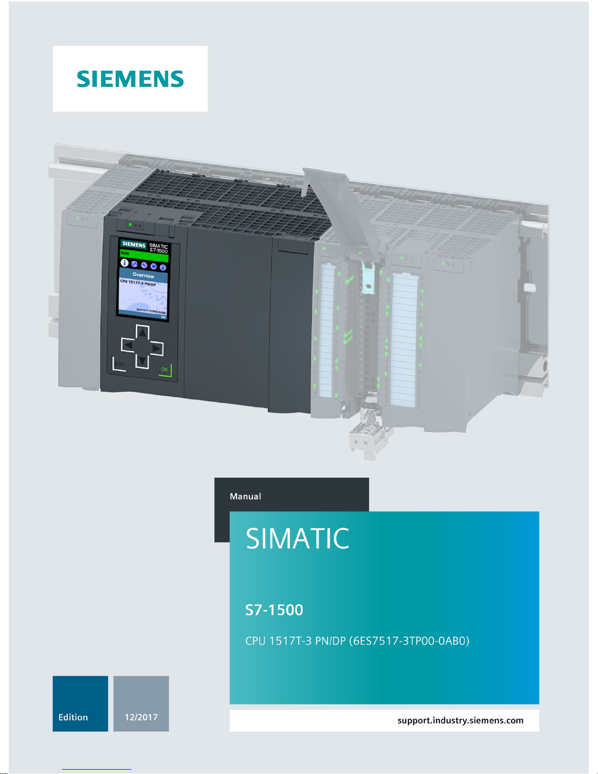
SIMATIC
S7-1500
CPU 1517T-3 PN/DP
(6ES7517-3TP00-0AB0)
Manual
12/2017
A5E36285525
-AB
Preface
Documentation guide
1
Product overview
2
Wiring
3
Interrupts, error messages,
diagnostics and system
alarms
4
Technical specifications
5
Dimension drawing
A
Page 3
Siemens AG
Division Digital Factory
Postfach 48 48
90026 NÜRNBERG
GERMANY
A5E36285525-AB
Ⓟ
11/2017 Subject to change
Copyright © Siemens AG 2016 - 2107.
All rights reserved
Legal information
Warning notice system
This manual contains notices you have to observe in order to ensure your personal safety, as well as to prevent
damage to property. The notices referring to your personal safety are highlighted in the manual by a safety alert
symbol, notices referring only to property damage have no safety alert symbol. These notices shown below are
graded according to the degree of danger.
DANGER
indicates that death or severe personal injury will result if proper precautions are not taken.
WARNING
indicates that death or severe personal injury may result if proper precautions are not taken.
CAUTION
indicates that minor personal injury can result if proper precautions are not taken.
NOTICE
indicates that property damage can result if proper precautions are not taken.
If more than one degree of danger is present, the warning notice representing the highest degree of danger will
be used. A notice warning of injury to persons with a safety alert symbol may also include a warning relating to
property damage.
Qualified Personnel
The product/system described in this documentation may be operated only by
personnel qualified
for the specific
task in accordance with the relevant documentation, in particular its warning notices and safety instructions.
Qualified personnel are those who, based on their training and experience, are capable of identifying risks and
avoiding potential hazards when working with these products/systems.
Proper use of Siemens products
Note the following:
WARNING
Siemens products may only be used for the applications described in the catalog and in the relevant technical
documentation. If products and components from other manufacturers are used, these must be recommended
or approved by Siemens. Proper transport, storage, installation, assembly, commissioning, operation and
maintenance are required to ensure that the products operate safely and without any problems. The permissible
ambient conditions must be complied with. The information in the relevant documentation must be observed.
Trademarks
All names identified by ® are registered trademarks of Siemens AG. The remaining trademarks in this publication
may be trademarks whose use by third parties for their own purposes could violate the rights of the owner.
Disclaimer of Liability
We have reviewed the contents of this publication to ensure consistency with the hardware and software
described. Since variance cannot be precluded entirely, we cannot guarantee full consistency. However, the
information in this publication is reviewed regularly and any necessary corrections are included in subsequent
editions.
Page 4

CPU 1517T-3 PN/DP (6ES7517-3TP00-0AB0)
4 Manual, 12/2017, A5E36285525-AB
Preface
Purpose of the documentation
This manual supplements the system manual of the S7-1500 automation system/ ET 200MP
distributed I/O system as well as the function manuals. This manual contains a description of
the module-specific information. The system-related functions are described in the system
manual. All system-spanning functions are described in the function manuals.
The information provided in this manual and the system manual enables you to commission
the CPU 1517T-3 PN/DP.
Conventions
STEP 7: In this documentation, "STEP 7" is used as a synonym for all versions of the
configuration and programming software "STEP 7 (TIA Portal)".
Please also observe notes marked as follows:
Note
A note contains important information on the product described in the documentation, on the
handling of the product or on the section of the document
ation to which particular attention
should be paid.
Security information
Siemens provides products and solutions with industrial security functions that support the
secure operation of plants, systems, machines and networks.
In order to protect plants, systems, machines and networks against cyber threats, it is
necessary to implement – and continuously maintain – a holistic, state-of-the-art industrial
security concept. Siemens' products and solutions constitute one element of such a concept.
Customers are responsible for preventing unauthorized access to their plants, systems,
machines and networks. Such systems, machines and components should only be
connected to an enterprise network or the internet if and to the extent such a connection is
necessary and only when appropriate security measures (e.g. firewalls and/or network
segmentation) are in place.
For additional information on industrial security measures that may be implemented, please
visit (http://www.siemens.com/industrialsecurity).
Siemens' products and solutions undergo continuous development to make them more
secure. Siemens strongly recommends that product updates are applied as soon as they are
available and that the latest product versions are used. Use of product versions that are no
longer supported, and failure to apply the latest updates may increase customers' exposure
to cyber threats.
To stay informed about product updates, subscribe to the Siemens Industrial Security
RSS Feed under (http://www.siemens.com/industrialsecurity).
Page 5

Preface
CPU 1517T-3 PN/DP (6ES7517-3TP00-0AB0)
Manual, 12/2017, A5E36285525-AB
5
Siemens Industry Online Support
You can find current information on the following topics quickly and easily here:
●
Product support
All the information and extensive know-how on your product, technical specifications,
FAQs, certificates, downloads, and manuals.
●
Application examples
Tools and examples to solve your automation tasks – as well as function blocks,
performance information and videos.
●
Services
Information about Industry Services, Field Services, Technical Support, spare parts and
training offers.
●
Forums
For answers and solutions concerning automation technology.
●
mySupport
Your personal working area in Industry Online Support for messages, support queries,
and configurable documents.
This information is provided by the Siemens Industry Online Support in the Internet
(https://support.industry.siemens.com).
Industry Mall
The Industry Mall is the catalog and order system of Siemens AG for automation and drive
solutions on the basis of Totally Integrated Automation (TIA) and Totally Integrated Power
(TIP).
Catalogs for all the products in automation and drives are available on the Internet
(https://mall.industry.siemens.com).
Page 6

CPU 1517T-3 PN/DP (6ES7517-3TP00-0AB0)
6 Manual, 12/2017, A5E36285525-AB
Table of contents
Preface ...................................................................................................................................................... 4
1 Documentation guide ................................................................................................................................. 7
2 Product overview ..................................................................................................................................... 11
2.1 New functions in firmware version V2.5 ................................................................................. 11
2.2 Applications of the S7-1500 CPU .......................................................................................... 12
2.3 Hardware properties .............................................................................................................. 19
2.4 Firmware functions ................................................................................................................. 21
2.5 Operator controls and display elements ................................................................................ 25
2.5.1 Front view of the CPU with closed front flap .......................................................................... 25
2.5.2 Front view of the CPU without front flaps .............................................................................. 27
2.5.3 Rear view of the CPU ............................................................................................................ 28
2.6 Mode selector ......................................................................................................................... 28
3 Wiring ...................................................................................................................................................... 29
4 Interrupts, error messages, diagnostics and system alarms .................................................................... 34
4.1 Status and error displays of the CPU..................................................................................... 34
5 Technical specifications ........................................................................................................................... 37
A Dimension drawing .................................................................................................................................. 50
A.1 Dimension drawing CPU 1517T-3 PN/DP ............................................................................. 50
Page 7
CPU 1517T-3 PN/DP (6ES7517-3TP00-0AB0)
Manual, 12/2017, A5E36285525-AB
7
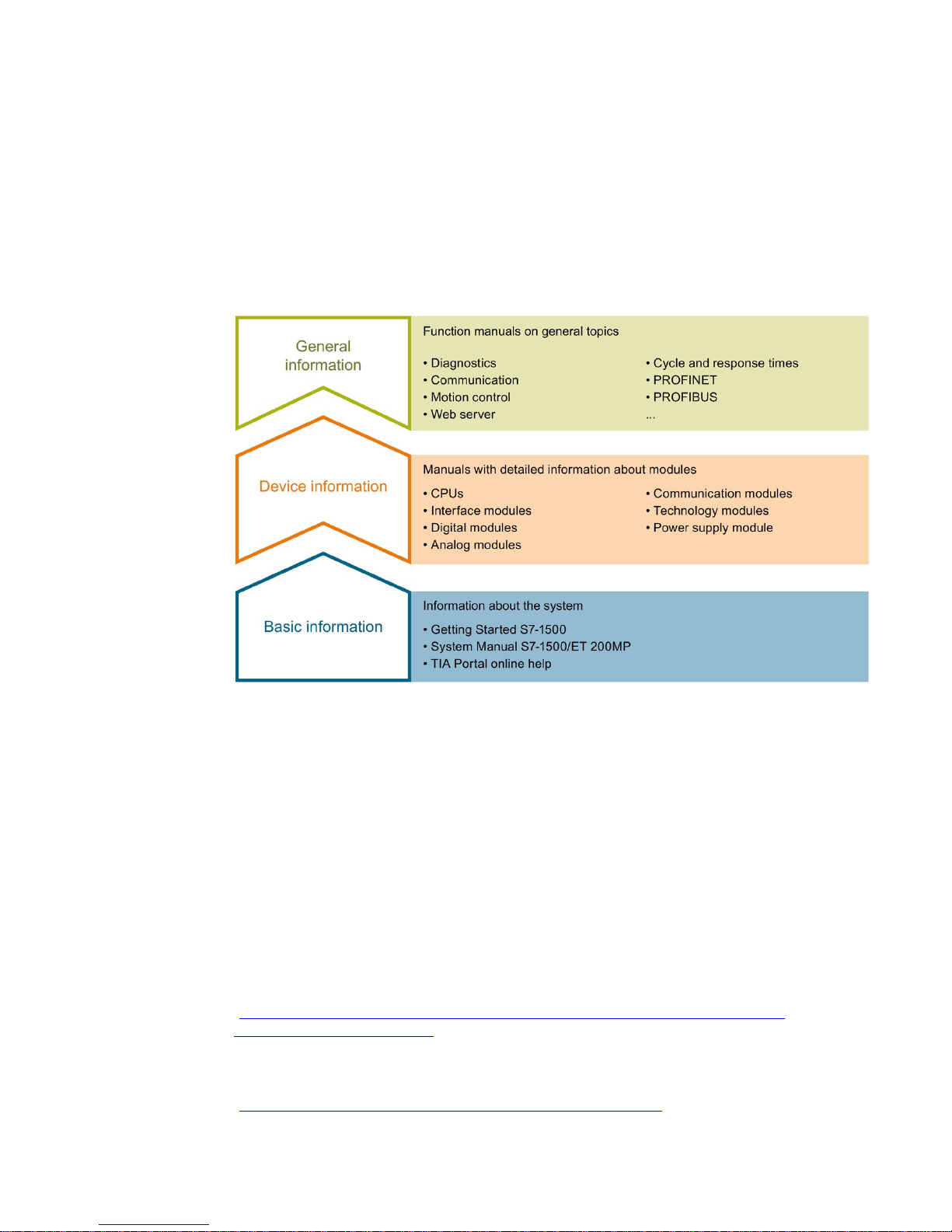
1
The documentation for the SIMATIC S7-1500 automation system and the
SIMATIC ET 200MP distributed I/O system is arranged into three areas.
This arrangement enables you to access the specific content you require.
Basic information
The System Manual and Getting Started describe in detail the configuration, installation,
wiring and commissioning of the SIMATIC S7-1500 and ET 200MP systems. The STEP 7
online help supports you in the configuration and programming.
Device information
Product manuals contain a compact description of the module-specific information, such as
properties, wiring diagrams, characteristics and technical specifications.
General information
The function manuals contain detailed descriptions on general topics regarding the
SIMATIC S7-1500 and ET 200MP systems, e.g. diagnostics, communication, motion control,
Web server, OPC UA.
You can download the documentation free of charge from the Internet
(http://w3.siemens.com/mcms/industrial-automation-systems-simatic/en/manual-
overview/Pages/Default.aspx).
Changes and supplements to the manuals are documented in a Product Information.
You can download the product information free of charge from the Internet
(https://support.industry.siemens.com/cs/us/en/view/68052815).
Page 8

Documentation guide
CPU 1517T-3 PN/DP (6ES7517-3TP00-0AB0)
8 Manual, 12/2017, A5E36285525-AB
Manual Collection S7-1500/ET 200MP
The Manual Collection contains the complete documentation on the SIMATIC S7-1500
automation system and the ET 200MP distributed I/O system gathered together in one file.
You can find the Manual Collection on the Internet
(https://support.industry.siemens.com/cs/ww/en/view/86140384).
SIMATIC S7-1500 comparison list for programming languages
The comparison list contains an overview of which instructions and functions you can use for
which controller families.
You can find the comparison list on the Internet
(https://support.industry.siemens.com/cs/ww/en/view/86630375).
"mySupport"
With "mySupport", your personal workspace, you make the best out of your Industry Online
Support.
In "mySupport", you can save filters, favorites and tags, request CAx data and compile your
personal library in the Documentation area. In addition, your data is already filled out in
support requests and you can get an overview of your current requests at any time.
You must register once to use the full functionality of "mySupport".
You can find "mySupport" on the Internet (https://support.industry.siemens.com/My/ww/en).
"mySupport" - Documentation
In the Documentation area in "mySupport" you can combine entire manuals or only parts of
these to your own manual.
You can export the manual as PDF file or in a format that can be edited later.
You can find "mySupport" - Documentation on the Internet
(http://support.industry.siemens.com/My/ww/en/documentation).
"mySupport" - CAx data
In the CAx data area in "mySupport", you can access the current product data for your CAx
or CAe system.
You configure your own download package with a few clicks.
In doing so you can select:
● Product images, 2D dimension drawings, 3D models, internal circuit diagrams, EPLAN
macro files
● Manuals, characteristics, operating manuals, certificates
● Product master data
You can find "mySupport" - CAx data on the Internet
(http://support.industry.siemens.com/my/ww/en/CAxOnline).
Page 9

Documentation guide
CPU 1517T-3 PN/DP (6ES7517-3TP00-0AB0)
Manual, 12/2017, A5E36285525-AB
9
Application examples
The application examples support you with various tools and examples for solving your
automation tasks. Solutions are shown in interplay with multiple components in the system separated from the focus on individual products.
You will find the application examples on the Internet
(https://support.industry.siemens.com/sc/ww/en/sc/2054).
TIA Selection Tool
With the TIA Selection Tool, you can select, configure and order devices for
Totally Integrated Automation (TIA).
This tool is the successor of the SIMATIC Selection Tool and combines the known
configurators for automation technology into one tool.
With the TIA Selection Tool, you can generate a complete order list from your product
selection or product configuration.
You can find the TIA Selection Tool on the Internet
(http://w3.siemens.com/mcms/topics/en/simatic/tia-selection-tool).
SIMATIC Automation Tool
You can use the SIMATIC Automation Tool to perform commissioning and maintenance
activities simultaneously on various SIMATIC S7 stations as a bulk operation independent of
the TIA Portal.
General function overview:
● Network browsing and creation of a table showing the accessible devices in the network.
● Flashing of device LEDs or HMI display to locate a device
● Downloading of addresses (IP, subnet, gateway) to a device
● Downloading the PROFINET name (station name) to a device
● Placing a CPU in RUN or STOP mode
● Setting the time in a CPU to the current time of your PG/PC
● Downloading a new program to a CPU or an HMI device
● Downloading from CPU, downloading to CPU or deleting recipe data from a CPU
● Downloading from CPU or deleting data log data from a CPU
● Backup/restore of data from/to a backup file for CPUs and HMI devices
● Downloading service data from a CPU
● Reading the diagnostics buffer of a CPU
● Performing a CPU memory reset
● Resetting devices to factory settings
● Downloading a firmware update to a device
You can find the SIMATIC Automation Tool on the Internet
(https://support.industry.siemens.com/cs/ww/en/view/98161300).
Page 10

Documentation guide
CPU 1517T-3 PN/DP (6ES7517-3TP00-0AB0)
10 Manual, 12/2017, A5E36285525-AB
PRONETA
With SIEMENS PRONETA (PROFINET network analysis), you analyze the PROFINET
network during commissioning. PRONETA features two core functions:
● The topology overview independently scans PROFINET network and all connected
components.
● The IO check is a fast test of the wiring and the module configuration of a system.
You can find SIEMENS PRONETA on the Internet
(https://support.industry.siemens.com/cs/ww/en/view/67460624).
Page 11

CPU 1517T-3 PN/DP (6ES7517-3TP00-0AB0)
Manual, 12/2017, A5E36285525-AB
11
2
2.1
New functions in firmware version V2.5
New functions of the CPUs firmware 2.5
This section lists the new features of the CPU with firmware version V2.5.
You can find additional information in the sections of this manual.
Table 2- 1 New functions of the CPUs with firmware version 2.5
New functions
Applications
Customer benefits
New technology object, kinematics Controlling of kinematics, such as
• Cartesian portals
• Roller pickers
• Delta pickers
• SCARA
Motion specification of paths
Individual motions and motion
sequences
Kinematics 2D, 3D, with and without
orientation axis
You can realize complex Motion
Control applications for controlling 2D,
3D and 4D kinematics.
Additional instructions for torque control You can apply an additives setpoint
torque in the drive.
You can predetermine torque limits in
the drive cyclically.
The torque actual value of the drive can
be evaluated directly in the TO-DB of
the axis.
You can pre-control the torque precisely for the axes, for example at winders
(predetermine traction torque and additionally torque limits in order to prevent
tearing of the material).
You can take the dynamic model of the
kinematics into consideration, precontrol the torque to be expected for
each axis and thus improve the preci-
sion.
Data adaption for SINAMICS S210 You can also use data adaption for the
new drive SINAMICS S210.
You gain time during the configuration
of the technology objects and the
drives.
MotionIn Through additional instructions motion
setpoints can be specified cyclically via
the application.
This means that specific technological
motion specifications are possible via
the application (for example at
winders).
Page 12

Product overview
2.2 Applications of the S7-1500 CPU
CPU 1517T-3 PN/DP (6ES7517-3TP00-0AB0)
12 Manual, 12/2017, A5E36285525-AB
2.2
Applications of the S7-1500 CPU
Area of application
SIMATIC S7-1500 is the modular control system for a wide variety of automation
applications in discrete automation.
The modular and fanless design, simple implementation of distributed structures, and
user-friendly operation make SIMATIC S7-1500 the economic and convenient solution for a
variety of tasks.
Areas of application of the SIMATIC S7-1500 are, for example:
● Special-purpose machines
● Textile machinery
● Packaging machines
● General mechanical engineering
● Controller engineering
● Machine tool engineering
● Installation engineering
● Electrical industry and crafts
● Automobile engineering
● Water/waste water
● Food & Beverage
Additional areas of application of the SIMATIC S7-1500T with extended Motion Control
functions are, for example:
● Packaging machines
● Converting application
● Assembly automation
Several CPUs with various levels of performance and a comprehensive range of modules
with many convenient features are available. Fail-safe CPUs enable use in fail-safe
applications. The modular design allows you to use only the modules that you need for your
application. The controller can be retrofitted with additional modules at any time to expand its
range of tasks.
High industrial capability from the high resistance to EMC, shock and vibration enable
universal use of the SIMATIC S7-1500.
Page 13

Product overview
2.2 Applications of the S7-1500 CPU
CPU 1517T-3 PN/DP (6ES7517-3TP00-0AB0)
Manual, 12/2017, A5E36285525-AB
13
Performance segments of the standard, compact, fail-safe and technology CPUs
The CPUs can be used for smaller and mid-range applications, as well as for the high-end
range of machine and plant automation.
Table 2- 2 Standard CPUs
CPU
Performance segment
PROFIBUS
interfaces
PROFINET
IO RT/IRT
interfaces
PROFINET
IO RT
interface
PROFINET
basic func-
tionality
Work
memory
Processing
time for bit
operations
CPU 1511-1 PN Standard CPU for
small to mid-range
applications
-- 1 -- -- 1.15 MB 60 ns
CPU 1513-1 PN Standard CPU for
mid-range applications
-- 1 -- -- 1.8 MB 40 ns
CPU 1515-2 PN Standard CPU for
mid-range to large
applications
-- 1 1 -- 3.5 MB 30 ns
CPU 1516-3 PN/
DP
Standard CPU for
high-end applications
and communication
tasks
1 1 1 -- 6 MB 10 ns
CPU 1517-3 PN/
DP
Standard CPU for
high-end applications
and communication
tasks
1 1 1 -- 10 MB 2 ns
CPU 1518-4 PN/
DP
CPU 1518-4 PN/
DP MFP
Standard CPU for
high-performance
applications, demanding communication
tasks and very short
reaction times
1 1 1 1 24 MB 1 ns
Table 2- 3 Compact CPUs
CPU
Performance segment
PROFIBUS
interfaces
PROFINET
IO RT/IRT
interfaces
PROFINET
IO RT
interface
PROFINET
basic func-
tionality
Work
memory
Processing
time for bit
operations
CPU 1511C-1
PN
Compact CPU for
small to mid-range
applications
-- 1 -- -- 1.175 MB 60 ns
CPU 1512C-1
PN
Compact CPU for
mid-range
applications
-- 1 -- -- 1.25 MB 48 ns
Page 14

Product overview
2.2 Applications of the S7-1500 CPU
CPU 1517T-3 PN/DP (6ES7517-3TP00-0AB0)
14 Manual, 12/2017, A5E36285525-AB
Table 2- 4 Fail-safe CPUs
CPU
Performance segment
PROFIBUS
interfaces
PROFINET
IO RT/IRT
interfaces
PROFINET
IO RT
interface
PROFINET
basic func-
tionality
Work
memory
Processing
time for bit
operations
CPU 1511F-1
PN
Fail-safe CPU for small
to mid-range applica-
tions
-- 1 -- -- 1.225 MB 60 ns
CPU 1511TF-1
PN
Fail-safe technology
CPU for small to
mid-range applications
-- 1 -- -- 1.225 MB 60 ns
CPU 1513F-1
PN
Fail-safe CPU for
mid-range applications
-- 1 -- -- 1.95 MB 40 ns
CPU 1515F-2
PN
Fail-safe CPU for
mid-range to large
applications
-- 1 1 -- 3.75 MB 30 ns
CPU 1515TF-2
PN
Fail-safe technology
CPU for demanding
applications and
communication tasks
-- 1 1 -- 3.75 MB 30 ns
CPU 1516F-3
PN/DP
Fail-safe CPU for
demanding applications
and communication
tasks
1 1 1 -- 6.5 MB 10 ns
CPU 1516TF-3
PN/DP
Fail-safe technology
CPU for demanding
applications and
communication tasks
1 1 1 -- 6.5 MB 10 ns
CPU 1517F-3
PN/DP
Fail-safe CPU for
demanding applications
and communication
tasks
1 1 1
-- 11 MB
2 ns
CPU 1517TF-3
PN/DP
Fail-safe technology
CPU for demanding
applications and
communication tasks
1 1 1
-- 11 MB
2 ns
CPU 1518F-4
PN/DP
CPU 1518F-4
PN/DP MFP
Fail-safe CPU for highperformance applications, demanding communication tasks and
very short reaction
times
1 1 1 1 26 MB 1 ns
Page 15

Product overview
2.2 Applications of the S7-1500 CPU
CPU 1517T-3 PN/DP (6ES7517-3TP00-0AB0)
Manual, 12/2017, A5E36285525-AB
15
Table 2- 5 Technology CPUs
CPU
Performance segment
PROFIBUS
interfaces
PROFINET
IO RT/IRT
interfaces
PROFINET
IO RT
interface
PROFINET
basic func-
tionality
Work
memory
Processing
time for bit
operations
CPU 1511T-1
PN
Technology CPU for
small to mid-range
applications
-- 1 -- -- 1.225 MB 60 ns
CPU 1515T-2
PN
Technology CPU for
mid-range to large
applications
-- 1 1 -- 3.75 MB 30 ns
CPU 1516T-3
PN/DP
Technology CPU for
high-end applications
and communication
tasks
1 1 1 -- 6.5 MB 10 ns
CPU 1517T-3
PN/DP
Technology CPU for
high-end applications
and communication
tasks
1 1 1 -- 11 MB 2 ns
CPU 1511TF-1
PN
CPU 1515TF-2
PN
CPU 1516TF-3
PN/DP
CPU 1517TF-3
PN/DP
These CPUs are described in the fail-safe CPUs
Performance segments of compact CPUs
The compact CPUs can be used for smaller to mid-range applications and have an
integrated analog and digital on-board I/O as well as integrated technology functions. The
following table shows the specific properties of the Compact CPUs.
CPU 1511C-1 PN
CPU 1512C-1 PN
Integrated analog inputs/outputs
5 inputs/2 outputs
5 inputs/2 outputs
Integrated digital inputs/outputs 16 inputs/16 outputs 32 inputs/32 outputs
High-speed counters 6 6
Frequency meter
6 (max. 100 kHz)
6 (max. 100 kHz)
Period duration measurement
6 channels
6 channels
Pulse width modulation (PWM output)
Max. 4 (up to 100 kHz)
Max. 4 (up to 100 kHz)
Pulse Train Output (PTO output)
Max. 4 (up to 100 kHz)
Max. 4 (up to 100 kHz)
Frequency output
Up to 100 kHz
Up to 100 kHz
Page 16

Product overview
2.2 Applications of the S7-1500 CPU
CPU 1517T-3 PN/DP (6ES7517-3TP00-0AB0)
16 Manual, 12/2017, A5E36285525-AB
Integrated Motion Control technology functions
All CPUs of SIMATIC S7-1500
support Motion Control technology functions. STEP 7 offers
Motion Control instructions standardized according to PLCopen for configuring and
connecting a drive to the CPU.
S7-1500 Motion Control supports the following technology objects:
● Speed-controlled axis
● Positioning axis
● Synchronous axis
● External encoders
● Output cam
● Cam track
● Measuring inputs
The technology CPUs of the SIMATIC S7-1500
offer enhanced Motion Control functions:
● Advanced synchronization functions
– Synchronization with specification of synchronous position
– Actual value coupling
– Shifting the master value of the following axis
– Camming
● Up to 4 encoders or measuring systems as actual position for position control
The technology CPUs of the SIMATIC S7-1500
additionally support the following technology
objects: – Cam – Kinematics
● Cam
● Kinematics
● Controlling of kinematics, such as
– Cartesian portals
– Roller pickers
– Delta pickers
– SCARA
Due to the supported technology functions, the S7-1500T CPUs are suitable for controlling
packaging machines, converting applications, assembly automation, etc.
Additional integrated technological functions
For effective commissioning, diagnostics and fast optimization of drives and controls, the
SIMATIC S7-1500 controller family offers extensive trace functions for all CPU tags.
In addition to drive integration, the SIMATIC S7-1500 has a PID compact closed-loop
controller; easy-to-configure blocks allow automatic optimization of the controller parameters
for optimized control quality.
Page 17

Product overview
2.2 Applications of the S7-1500 CPU
CPU 1517T-3 PN/DP (6ES7517-3TP00-0AB0)
Manual, 12/2017, A5E36285525-AB
17
Other technology functions
Technology modules also implement functions such as high-speed counting, position
detection and measuring functions and pulse generators (PTO, PWM and frequency output).
For compact CPU 1511C-1 PN and CPU 1512C-1 PN CPUs, these functions are already
integrated and can be implemented without additional technology modules.
SIWAREX is a versatile and flexible weighing module, which you can use as a static scale
for operation.
Security Integrated
In conjunction with STEP 7, each CPU offers password-based know-how protection against
unauthorized reading out or modification of the program blocks.
Copy protection provides reliable protection against unauthorized reproduction of program
blocks. With copy protection, individual blocks on the SIMATIC memory card can be tied to
its serial number so that the block can only be run if the configured memory card is inserted
into the CPU.
In addition, you can assign various access rights to different user groups in the controller
using four different authorization levels.
Improved manipulation protection allows changed or unauthorized transfers of engineering
data to be detected by the controller.
The use of an Ethernet CP (CP 1543-1) provides the user with additional access protection
through a firewall or possibilities to establish secure VPN connections.
Safety Integrated
The fail-safe CPUs are intended for users who want to implement demanding standard and
fail-safe applications both centrally and decentrally.
These fail-safe CPUs allow the processing of standard and safety programs on a single
CPU. This allows fail-safe data to be evaluated in the standard user program. The integration
thereby provides the system advantages and the extensive functionality of SIMATIC for
fail-safe applications.
The fail-safe CPUs are certified for use in safety mode up to:
● Safety class (Safety Integrity Level) SIL 3 according to IEC 61508:2010
● Performance Level (PL) e and Category 4 according to ISO 13849-1:2006 or according to
EN ISO 13849-1:2008
Additional password protection for F-configuration and F-program is set up for IT security.
In addition to the CPUs, further components such as SINAMICS drives dispose of integrated
safety functions. Additional information about integrated safety functions in drives can be
found in the manuals for the respective products.
Page 18

Product overview
2.2 Applications of the S7-1500 CPU
CPU 1517T-3 PN/DP (6ES7517-3TP00-0AB0)
18 Manual, 12/2017, A5E36285525-AB
Design and handling
All CPUs of the SIMATIC S7-1500 product series feature a display with plain text
information. The display provides the user with information on the order numbers, firmware
version, and serial number of all connected modules. In addition, the IP address of the CPU
and other network settings can be adapted locally without a programming device. Error
messages are immediately shown on the display in plain text. In the case of servicing, plant
downtimes are minimized by quick access to diagnostics alarms. Detailed information about
this and a multitude of other display functions is available in the SIMATIC S7-1500 Display
Simulator (http://www.automation.siemens.com/salesmaterial-as/interactive-manuals/getting-
started_simatic-s7-1500/disp_tool/start_en.html).
Uniform front connectors for all modules and integrated potential bridges for flexible
formation of potential groups simplifies storage. Additional components such as circuit
breakers, relays, etc., can be installed quickly and easily, since a DIN rail is implemented in
the rail of the S7-1500. The CPUs of the SIMATIC S7-1500 product series can be expanded
centrally and in a modular fashion with signal modules. Space-saving expansion enables
flexible adaptation to each application.
The system cabling for digital signal modules enables fast and clear connection to sensors
and actuators from the field (fully modular connection consisting of front connector modules,
connection cables and I/O modules), as well as easy wiring inside the control cabinet
(flexible connection consisting of front connectors with assembled single conductors).
System diagnostics and alarms
Integrated system diagnostics is activated by default for the CPUs. The different types of
diagnostics are configured instead of programmed. System diagnostics information is shown
uniformly and in plain text on the display of the CPU, in STEP 7, on the HMI and on the Web
server, even for alarms related to drives. This information is available in RUN mode, but also
in STOP mode of the CPU. The diagnostic information is updated automatically when you
configure new hardware components.
The CPU is available as a central interrupt server in up to three project languages. The HMI
takes over the display in the project languages specified for the CPU. If you require message
texts in additional languages, you can load these via the configured connection to your HMI.
The CPU, STEP 7 and your HMI guarantee data consistency without additional engineering
steps. The maintenance work is easier.
Page 19
Product overview
2.3 Hardware properties
CPU 1517T-3 PN/DP (6ES7517-3TP00-0AB0)
Manual, 12/2017, A5E36285525-AB
19
2.3
Hardware properties
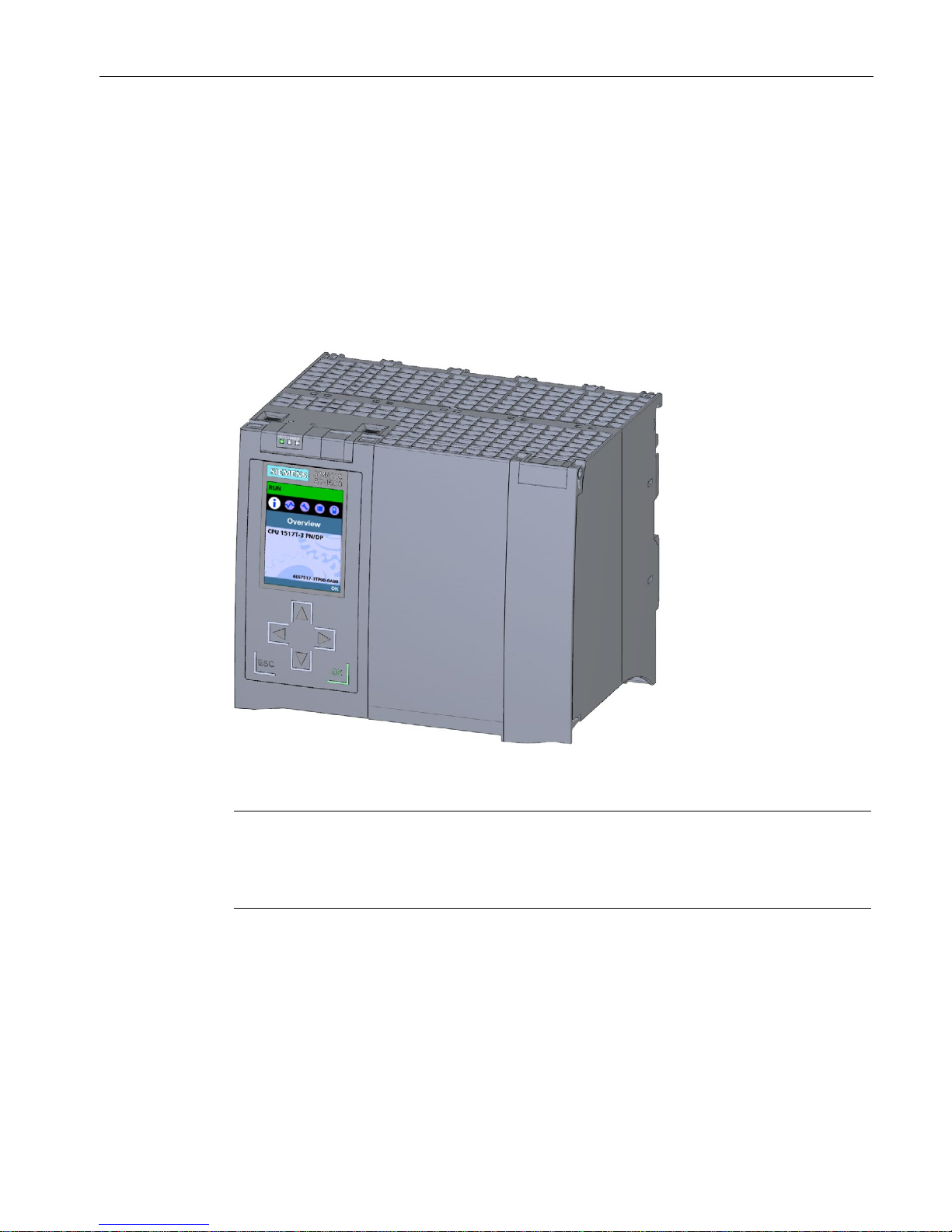
Article number
6ES7517-3TP00-0AB0
View of the module
The following figure shows the CPU 1517T-3 PN/DP.
Figure 2-1 CPU 1517T-3 PN/DP
Note
Protective film
Note that a protective film is applied to the display in the delivery state of the CPU. Remove
the protective film if necessary.
Page 20

Product overview
2.3 Hardware properties
CPU 1517T-3 PN/DP (6ES7517-3TP00-0AB0)
20 Manual, 12/2017, A5E36285525-AB
Properties
The CPU 1517T-3 PN/DP has the following properties:
Property
Description
Additional information
CPU display
All CPUs of the SIMATIC S7-1500 product series
feature a display with plain text information. The display
provides information on order numbers, firmware
version and serial numbers of all connected modules.
In addition, you can set the IP address of the CPU and
carry out further network settings. The display shows
occurring error messages directly in plain text.
In addition to the functions listed here, a multitude of
other functions that are described in the SIMATIC
S7-1500 Display Simulator are shown on the display.
• S7-1500, ET 200MP system
manual
(http://support.automation.sieme
ns.com/WW/view/en/59191792)
• SIMATIC S7-1500 Display
Simulator
(http://www.automation.siemens.
com/salesmaterial-as/interactivemanuals/getting-started_simatics7-1500/disp_tool/start_en.html)
Supply voltage
The 24 V DC supply voltage is supplied via a 4-pole
connection plug that is located at the front of the CPU.
• Chapter Wiring (Page 29)
• S7-1500, ET 200MP system
manual
(http://support.automation.sieme
ns.com/WW/view/en/59191792)
PROFIBUS DP
PROFIBUS interface (X3) The interface serves to connect to a PROFIBUS net-
work.
PROFIBUS function manual
(https://support.industry.siemens.co
m/cs/ww/en/view/59193579)
Operation of the CPU as
DP master
In the role as a DP master, the CPU addresses the
connected DP slaves. The CPU cannot assume the
role of a DP slave.
PROFINET IO
PROFINET interface
(X1 P1 R, X1 P2 R)
The interface has two ports. In addition to basic
PROFINET functionality, its also supports
PROFINET IO RT (real time) and IRT (isochronous real
time).
PROFINET function manual
(https://support.industry.siemens.co
m/cs/ww/en/view/49948856)
PROFINET interface
(X2 P1)
The interface has two ports. In addition to basic
PROFINET functionality, its also supports
PROFINET IO RT (real time).
Operation of the CPU as
• IO controller
• I-device
•
IO controller:
As an IO controller the CPU addresses the
connected IO devices
•
I-device:
As an I-device (intelligent IO device) the CPU is
assigned to a higher-level IO controller and is used
in the process as an intelligent pre-processing unit
of sub-processes
Accessories
You can find information on "Accessories/spare parts" in the S7-1500, ET 200MP system
manual (http://support.automation.siemens.com/WW/view/en/59191792).
Page 21

Product overview
2.4 Firmware functions
CPU 1517T-3 PN/DP (6ES7517-3TP00-0AB0)
Manual, 12/2017, A5E36285525-AB
21
2.4
Firmware functions
Functions
The CPU 1517T-3 PN/DP supports the following functions:
Function
Description
Additional information
Integrated system
diagnostics
The system automatically generates the messages for
the system diagnostics and outputs these messages
via a programming device/PC, HMI device, the Web
server or the integrated display. System diagnostics
information is also available when the CPU is in STOP
mode.
Diagnostics function manual
(http://support.automation.siemens.c
om/WW/view/en/59191792)
Integrated Web server
The Web server lets you access the CPU data by
means of a network. Evaluations, diagnostics, and
modifications are thus possible over long distances.
Monitoring and evaluation is possible without STEP 7;
all you need is a Web browser. Make sure that you take
appropriate measures (e.g. limiting network access,
using firewalls) to protect the CPU from being compromised.
• Web server function manual
(http://support.automation.sieme
ns.com/WW/view/en/59193560)
• Security with SIMATIC S7
controllers system manual
(https://support.industry.siemens.
com/cs/ww/en/view/90885010)
Integrated trace
functionality
Trace functionality supports you in troubleshooting
and/or optimizing the user program.
You record device tags and evaluate the recordings
with the trace and logic analyzer function. Tags are, for
example, drive parameters or system and user tags of
a CPU.
The device saves the recordings. You can read out and
permanently save the recordings with the configuration
system (ES), if required. The trace and logic analyzer
function is therefore suitable for monitoring highly
dynamic processes.
The trace record can also be displayed through the
Web server.
Using the trace and logic analyzer
function function manual
(http://support.automation.siemens.c
om/WW/view/en/64897128)
OPC UA
With OPC UA, you can exchange data via an open and
manufacturer-neutral communication protocol. The
CPU can act as an OPC UA DA server. The CPU acting as the OPC UA server can communicate with
OPC UA clients.
The OPC UA Companion Specification allows methods
to be specified uniformly and independently of the
manufacturer. Using these specified methods, you can
easily integrate devices from various manufacturers
into your plants and production processes.
Communication function manual
(https://support.industry.siemens.co
m/cs/ww/en/view/59192925)
Configuration control
You can use configuration control to operate different
real hardware configurations with a configured maximum configuration of the hardware. This means that, in
series machine manufacturing in particular, you have
the option of operating/configuring different configura-
tion variants of a machine with a single project.
S7-1500, ET 200MP system manual
(http://support.automation.siemens.c
om/WW/view/en/59191792)
Page 22

Product overview
2.4 Firmware functions
CPU 1517T-3 PN/DP (6ES7517-3TP00-0AB0)
22 Manual, 12/2017, A5E36285525-AB
Function
Description
Additional information
PROFINET IO
RT (real time) RT prioritizes PROFINET IO telegrams over standard
telegrams. This ensures the required determinism in
the automation technology. In this process the data is
transferred via prioritized Ethernet telegrams.
PROFINET function manual
(http://support.automation.siemens.c
om/WW/view/en/49948856)
IRT
(isochronous real time)
A reserved bandwidth within the send clock is available
for IRT data. The reserved bandwidth ensures that the
IRT data can be transmitted in time-synchronized intervals, unaffected by other high network loading
(e.g. TCP/IP communication or additional real time
communication). Update times with maximum
determinism can be realized through IRT. Isochronous
applications are possible with IRT.
Isochronous mode The Isochronous mode system property acquires
measured values and process data and processes the
signal in a fixed system clock. Isochronous mode thus
contributes to high control quality and hence to greater
manufacturing precision. Isochronous mode reduces
possible fluctuations of the process reaction times to a
minimum. Time-assured processing makes higher
machine cycles possible.
MRP (Media Redundancy
Protocol)
It is possible to establish redundant networks via the
Media Redundancy Protocol. Redundant transmission
links (ring topology) ensure that an alternative
communication path is made available if a transmission
link fails. The PROFINET devices that are part of this
redundant network form an MRP domain.
RT operation is possible with the use of MRP.
MRPD
(Media Redundancy with
Planned Duplication)
The advantage of the MRP extension MRPD is that, in
the event of a failure of a device or a line in the ring, all
other devices continue to be supplied with IO data
without interruption and with short update times.
MRPD is based on IRT and MRP. To realize media
redundancy with short update times, the PROFINET
devices participating in the ring send their data in both
directions. The devices receive this data at both ring
ports so that there is no reconfiguration time.
Shared device The "Shared device" function allows you to divide the
modules or submodules of an IO device up among
different IO controllers. Numerous IO controllers are
often used in larger or widely distributed systems.
Without the "Shared device" function, each I/O module
of an IO device is assigned to the same IO controller. If
sensors that are physically close to each other must
provide data to different IO controllers, several IO devices are required. The "Shared device" function allows
the modules or submodules of an IO device to be
divided up among different IO controllers, thus allowing
flexible automation concepts. You can, for example,
combine I/O modules that are physically close to each
other in one IO device.
Page 23

Product overview
2.4 Firmware functions
CPU 1517T-3 PN/DP (6ES7517-3TP00-0AB0)
Manual, 12/2017, A5E36285525-AB
23
Function
Description
Additional information
PROFIenergy PROFIenergy is a PROFINET-based data interface for
switching off consumers centrally and with full coordination during pause times regardless of the manufacturer or device type. Through this, the process should
only be provided with the energy that is absolutely
required. The majority of the energy is saved by the
process; the PROFINET device itself only contributes a
few watts of savings potential.
Integrated technology
Motion Control S7-1500 CPUs support the controlled positioning and
traveling of axes via S7-1500 Motion Control functions
by means of the following technology objects:
Speed-controlled axes, positioning axes, synchronized
axes, external encoders, cams, cam tracks and
measuring inputs.
• Speed-controlled axis for controlling a drive with
speed specification
• Positioning axis for position-controlled positioning of
a drive
• Synchronous axis to interconnect with a master
value. The axis is synchronized to the master axis
position.
• External encoder for detecting the actual position of
an encoder and its use as a master value for
synchronous operation
• Cams, cam track for position-dependent generation
of switching signals
• Measuring input for fast, accurate and event-
dependent sensing of actual positions
You program the technology objects with Motion
Control instructions according to PLCopen.
S7-1500 Motion Control function
manual
(http://support.automation.siemens.c
om/WW/view/en/109749262)
Extended Motion Control
functions
The technology CPUs
of the SIMATIC S7-1500 also
support extended Motion Control functions:
• Advanced synchronization functions
– Synchronization with specification of the
synchronous position
– Actual value coupling
– Shifting of the master value at following axis
– Camming
• Cam
• Up to 4 encoders or measuring systems as actual
position for position control
• Controlling of kinematics, such as
– Cartesian portals
– Roller pickers
– Delta pickers
– SCARA
S7-1500T Motion Control function
manual
(https://support.industry.siemens.co
m/cs/ww/en/view/109749263)
S7-1500T Kinematics Functions
V4.0 in TIA Portal V15
(https://support.industry.siemens.co
m/cs/ww/en/view/109749264)
Function manual
Page 24

Product overview
2.4 Firmware functions
CPU 1517T-3 PN/DP (6ES7517-3TP00-0AB0)
24 Manual, 12/2017, A5E36285525-AB
Function
Description
Additional information
Integrated closed-loop
control functionality
• PID Compact (continuous PID controller)
• PID 3Step (step controller for integrating actuators)
• PID Temp (temperature controller for heating and
cooling with two separate actuators)
PID control function manual
(https://support.industry.siemens.co
m/cs/ww/en/view/108210036)
Integrated safety
Know-how protection The know-how protection protects user blocks against
unauthorized access and modifications.
S7-1500, ET 200MP system manual
(http://support.automation.siemens.c
om/WW/view/en/59191792)
Copy protection Copy protection links user blocks to the serial number
of the SIMATIC memory card or to the serial number of
the CPU. User programs cannot run without the corre-
sponding SIMATIC memory card or CPU.
Access protection Extended access protection provides high-quality
protection against unauthorized configuration changes.
You can use authorization levels to assign separate
rights to different user groups.
Integrity protection The CPUs dispose of integrity protection by default.
Integrity protection identifies possible manipulations of
engineering data on the SIMATIC memory card or
during data transfer between TIA Portal and CPU.
Integrity protection also checks the communication
from a SIMATIC HMI system to the CPU for possible
manipulations of engineering data.
If integrity protection identifies the manipulation of
engineering data, the user receives a corresponding
message.
Password provider As an alternative to manual password input you can
connect a password provider to STEP 7. A password
provider offers the following advantages:
• Convenient handling of passwords. STEP 7 reads
the password automatically for the blocks. This
saves you time.
• Optimum block protection because the users do not
know the password itself.
Page 25

Product overview
2.5 Operator controls and display elements
CPU 1517T-3 PN/DP (6ES7517-3TP00-0AB0)
Manual, 12/2017, A5E36285525-AB
25
2.5
Operator controls and display elements
2.5.1
Front view of the CPU with closed front flap
The figure below shows the front view of the CPU 1517T-3 PN/DP.
①
LEDs for the current operating mode and diagnostics status of the CPU
②
Front panel with display
③
Display
④
Control keys
⑤
Front panel of the PROFIBUS interface
Figure 2-2 View of the CPU 1517T-3 PN/DP (with front panels) - front
Note
Temperature range for display
To increase its service life, the display switches off at a temperature below the permitted
operating
temperature of the device. When the display cools down, it automatically switches
itself on again. When the display is switched off, the LEDs continue to show the status of the
CPU.
You can find additional information on the temperatures at which the displ
ay switches itself
on and off in the technical specifications.
Page 26
Product overview
2.5 Operator controls and display elements
CPU 1517T-3 PN/DP (6ES7517-3TP00-0AB0)
26 Manual, 12/2017, A5E36285525-AB
Removing and fitting the front panel with display
You can remove and fit the front panel with display during operation.
WARNING
Personal injury and damage to property may occur
If you remove or fit the front panel of an S7-1500 automation system during operation,
personal injury or damage to property can occur in zone 2 hazardous areas.
Before you remove or fit the front panel, always switch off the power supply to the S7-1500
automation system in hazardous area zone 2. The CPU maintains its operating mode.
Locking the front panel
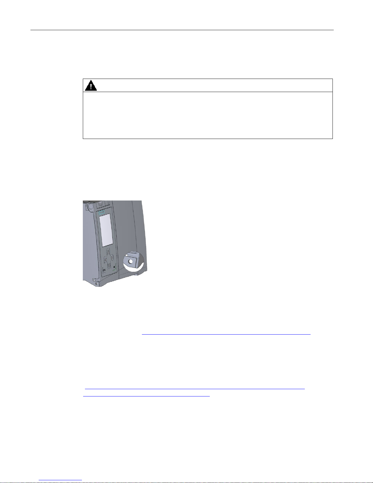
You can lock the wide front panel with display as well as the narrow front panel of the
PROFIBUS interface to protect your CPU against unauthorized access. You can attach a
security seal or a padlock with a diameter of 3 mm to the front panels.
Figure 2-3 Locking latch on the CPU
In addition to the mechanical lock, you can also block access to a password-protected CPU
on the display (local lock) and assign a password for the display. You can find additional
information on the display, the configurable protection levels and local locking in the
S7-1500, ET 200MP (http://support.automation.siemens.com/WW/view/en/59191792)
system manual.
Reference
You can find detailed information on the individual display options, a training course and a
simulation of the available menu commands in the SIMATIC S7-1500 Display Simulator
(http://www.automation.siemens.com/salesmaterial-as/interactive-manuals/getting-
started_simatic-s7-1500/disp_tool/start_en.html).
Page 27

Product overview
2.5 Operator controls and display elements
CPU 1517T-3 PN/DP (6ES7517-3TP00-0AB0)
Manual, 12/2017, A5E36285525-AB
27
2.5.2
Front view of the CPU without front flaps
The figure below shows the operator controls and connection elements of the
CPU 1517T-3 PN/DP.
①
Mode selector
②
No function
③
PROFIBUS interface (X3)
④
Fixing screws
⑤
Connection for supply voltage
⑥
PROFINET IO interface (X2) with 1 port
⑦
PROFINET IO interface (X1) with 2 ports
⑧
MAC addresses of the interfaces
⑨
LEDs for the 3 ports of the PROFINET interfaces X1 and X2
⑩
Slot for the SIMATIC memory card
⑪
Display connection
⑫
LEDs for the current operating mode and diagnostics status of the CPU
Figure 2-4 View of the CPU 1517T-3 PN/DP (without front panels) - front
Page 28

Product overview
2.6 Mode selector
CPU 1517T-3 PN/DP (6ES7517-3TP00-0AB0)
28 Manual, 12/2017, A5E36285525-AB
2.5.3
Rear view of the CPU
The following figure shows the connection elements on the rear of the CPU 1517T-3 PN/DP.
①
Shield contact surfaces
②
Plug-in connection for power supply
③
Plug-in connection for backplane bus
④
Fixing screws
Figure 2-5 View of the CPU 1517T-3 PN/DP - rear
2.6
Mode selector
You use the mode selector to set the operating mode of the CPU.
The following table shows the meaning of the corresponding operation of the operating mode
buttons.
Table 2- 6 Meaning of the mode switches
Operation of the mode switch
Meaning
Explanation
RUN RUN mode The CPU is executing the user program.
STOP
STOP mode
The user program is not executed. (STOP ACTIVE LED lights up).
MRES
Memory reset Position for CPU memory reset.
Page 29

CPU 1517T-3 PN/DP (6ES7517-3TP00-0AB0)
Manual, 12/2017, A5E36285525-AB
29
3
This section provides information on the pin assignment of the individual interfaces and the
block diagram of the CPU 1517T-3 PN/DP.
24 V DC supply voltage (X80)
The connector for the supply voltage is plugged in when the CPU ships from the factory.
The following table shows the pin assignment for a 24 V DC power supply.
①
+24 V DC of the supply voltage
②
Ground of the supply voltage
③
Ground of the supply voltage for loop-through (maximum of 10 A permitted)
④
+24 V DC of the supply voltage for loop-through (maximum of 10 A permitted)
⑤
Spring opener (one spring opener per terminal)
Bridged internally:
① and ④
② and ③
Figure 3-1 Supply voltage connection
If the CPU is supplied by a system power supply, it is not necessary to connect the 24 V
supply.
Page 30

Wiring
CPU 1517T-3 PN/DP (6ES7517-3TP00-0AB0)
30 Manual, 12/2017, A5E36285525-AB
PROFINET interface X1 with 2-port switch (X1 P1 R and X1 P2 R)
The assignment corresponds to the Ethernet standard for an RJ45 plug.
● When autonegotiation is deactivated, the RJ45 socket is allocated as a switch (MDI-X).
● When autonegotiation is activated, autocrossing is in effect and the RJ45 socket is
allocated either as data terminal equipment (MDI) or a switch (MDI-X).
Figure 3-2 PROFINET
PROFINET interface X2 with 1 port (X2 P1)
The assignment corresponds to the Ethernet standard for an RJ45 plug.
Autocrossing is always active on X2. This means the RJ45 socket is allocated either as data
terminal equipment (MDI) or a switch (MDI-X).
Page 31

Wiring
CPU 1517T-3 PN/DP (6ES7517-3TP00-0AB0)
Manual, 12/2017, A5E36285525-AB
31
PROFIBUS interface X3
The table below shows the pin assignment of the PROFIBUS interface. The assignment
corresponds to the standard assignment of an RS485 interface.
Table 3- 1 PROFIBUS interface pin assignment
View
Signal name
Designation
1 - -
2 - -
3
RxD/TxD-P
Data line B
4
RTS
Request to send
5
M5V2
Data reference potential (from station)
6
P5V2
Supply plus (from station)
7 - -
8
RxD/TxD-N
Data line A
9 - -
Note
Supply of I/O devices
CPU
1517T-3 PN/DP does not provide a 24 V
DC power supply on the PROFIBUS interface.
I/O devices (for example, PC adapter USB) are therefore only operational on the interface in
conj
unction with a plug-in power supply set for external power supply.
The innovative successor product, PC adapter USB
A2, receives the required power supply
via the USB port. The USB
A2 PC adapter therefore does not require a 24 V DC supply
voltage and can b
e operated
without
a plug-in power supply set for external power supply.
Reference
You can find additional information on the topics of "Wiring the CPU" and "Accessories/spare
parts" in the S7-1500, ET 200MP
(http://support.automation.siemens.com/WW/view/en/59191792) system manual.
Page 32

Wiring
CPU 1517T-3 PN/DP (6ES7517-3TP00-0AB0)
32 Manual, 12/2017, A5E36285525-AB
Assignment of the MAC addresses
CPU 1517T-3 PN/DP has two PROFINET interfaces. The first interface has two ports. Each
of the PROFINET interfaces has a MAC address and each of the PROFINET ports has its
own MAC address. In total, the CPU 1517T-3 PN/DP has five MAC addresses.
The MAC addresses of the PROFINET ports are needed for the LLDP protocol, for example
for the neighborhood discovery function.
The number range of the MAC addresses is sequential. The first and last MAC address are
lasered on the rating plate on the right side of each CPU 1517T-3 PN/DP.
The table below shows how the MAC addresses are assigned.
Table 3- 2 Assignment of the MAC addresses
Assignment
Labeling
MAC address 1
PROFINET interface X1
(visible in STEP 7 for accessible devices)
• Front, lasered
• Right side, lasered
(start of number range)
MAC address 2
Port X1 P1 R (required for LLDP, for example)
• Front and right side, not lasered
MAC address 3
Port X1 P2 R (required for LLDP, for example)
• Front and right side, not lasered
MAC address 4
PROFINET interface X2
(visible in STEP 7 for accessible devices)
• Front, lasered
• Right side, not lasered
MAC address 5
Port X2 P1 (required for LLDP, for example)
• Front, not lasered
• Right side, lasered
(start of number range)
Page 33

Wiring
CPU 1517T-3 PN/DP (6ES7517-3TP00-0AB0)
Manual, 12/2017, A5E36285525-AB
33
Block diagram
The following figure shows the block diagram of the CPU 1517T-3 PN/DP.
①
Display
PN X1 P1 R
PROFINET interface X1 Port 1
②
RUN/STOP/MRES mode selector
PN X1 P2 R
PROFINET interface X1 Port 2
③
Electronics
PN X2 P1
PROFINET interface X2 Port 1
④
PROFINET 2-port switch
PB X3
PROFIBUS interface X3
⑤
PROFIBUS DP driver
L+
24 V DC supply voltage
⑥
Backplane bus interface
M
Ground
⑦
Internal supply voltage
R/S
RUN/STOP LED (yellow/green)
X50
SIMATIC memory card
ER
ERROR LED (red)
X80 24 V DC
Infeed of supply voltage
MT
MAINT LED (yellow)
X1 P1, X1 P2, X2 P1
LED Link TX/RX
Figure 3-3 Block diagram of the CPU 1517T-3 PN/DP
Page 34

CPU 1517T-3 PN/DP (6ES7517-3TP00-0AB0)
34 Manual, 12/2017, A5E36285525-AB
alarms
4
The status and error displays of the CPU 1517T-3 PN are described below.
You can find additional information on the topic of "Interrupts" in the STEP 7 online help.
You can find additional information on the topic of "Diagnostics" and "System alarms" in the
Diagnostics (http://support.automation.siemens.com/WW/view/en/59192926) function
manual.
4.1
Status and error displays of the CPU
LED display
The following figure shows the LED displays of the CPU 1517T-3 PN/DP.
①
RUN/STOP LED (yellow/green LED)
②
ERROR LED (red LED)
③
MAINT LED (yellow LED)
④
No function
⑤
LINK RX/TX LED for port X1 P1 (yellow/green LED)
⑥
LINK RX/TX LED for port X1 P2 (yellow/green LED)
⑦
LINK RX/TX LED for port X2 P1 (yellow/green LED)
Figure 4-1 LED display of the CPU 1517T-3 PN/DP (without front panel)
Page 35

Interrupts, error messages, diagnostics and system alarms
4.1 Status and error displays of the CPU
CPU 1517T-3 PN/DP (6ES7517-3TP00-0AB0)
Manual, 12/2017, A5E36285525-AB
35
Meaning of the RUN/STOP, ERROR and MAINT LEDs
The CPU 1517T-3 PN/DP has three LEDs to signal the current operating status and
diagnostics status. The following table shows the meaning of the various combinations of
colors for the RUN/STOP, ERROR and MAINT LEDs.
Table 4- 1 Meaning of the LEDs
RUN/STOP LED
ERROR LED
MAINT LED
Meaning
LED off
LED off
LED off
Missing or insufficient supply voltage on the CPU.
LED off
LED flashes red
LED off
An error has occurred.
LED lit green
LED off
LED off
CPU is in RUN mode.
LED lit green
LED flashes red
LED off
A diagnostics event is pending.
LED lit green
LED off
LED lit yellow
Maintenance demanded for the plant.
The affected hardware must be checked/replaced
within a short period of time.
Active Force job
PROFIenergy pause
LED lit green
LED off
LED flashes yellow
Maintenance required for the plant.
The affected hardware must be checked/replaced
within a foreseeable period of time.
Bad configuration
LED lit green
LED flashes red
LED off
An error has occurred.
LED lit yellow
LED flashes red
LED off
LED lit yellow
LED off
LED flashes yellow
Firmware update successfully completed.
LED lit yellow
LED off
LED off
CPU is in STOP mode.
LED lit yellow
LED flashes red
LED flashes yellow
The program on the SIMATIC memory card is
causing an error.
CPU defective
LED flashes yellow
LED off
LED off
CPU is performing internal activities during STOP,
e.g. startup after STOP.
Download of the user program from the SIMATIC
memory card
CPU carries out a program with active breakpoint.
LED flashes
yellow/green
LED off
LED off
Startup (transition from RUN → STOP)
Page 36

Interrupts, error messages, diagnostics and system alarms
4.1 Status and error displays of the CPU
CPU 1517T-3 PN/DP (6ES7517-3TP00-0AB0)
36 Manual, 12/2017, A5E36285525-AB
RUN/STOP LED
ERROR LED
MAINT LED
Meaning
LED flashes
yellow/green
LED flashes red
LED flashes yellow
Startup (CPU booting)
Test of LEDs during startup, inserting a module.
LED flashing test
Meaning of LINK RX/TX LED
Each port has a LINK RX/TX LED. The table below shows the various "LED scenarios" of
ports for the CPU 1517T-3 PN/DP.
Table 4- 2 Meaning of the LEDs
LINK TX/RX LED
Meaning
LED off
There is no Ethernet connection between the PROFINET interface of the PROFINET device
and the communication partner.
No data is currently being sent/received via the PROFINET interface.
There is no LINK connection.
LED flashes green
The "LED flashing test" is being performed.
LED lit green
There is an Ethernet connection between the PROFINET interface of your PROFINET
device and a communication partner.
LED flickers yellow
Data is currently being received from or sent to a communications partner on Ethernet via
the PROFINET interface of the PROFINET device.
Page 37

CPU 1517T-3 PN/DP (6ES7517-3TP00-0AB0)
Manual, 12/2017, A5E36285525-AB
37
5
Article number
6ES7517-3TP00-0AB0
General information
Product type designation
CPU 1517T-3 PN/DP
HW functional status
FS05
Firmware version
V2.5
Engineering with
• STEP 7 TIA Portal configurable/integrated
as of version
V15 (FW V2.5) / V14 (FW V2.0) or higher
Configuration control
via dataset
Yes
Display
Screen diagonal [cm] 6.1 cm
Control elements
Number of keys
6
Mode selector switch
1
Supply voltage
Type of supply voltage
24 V DC
permissible range, lower limit (DC)
19.2 V
permissible range, upper limit (DC)
28.8 V
Reverse polarity protection
Yes
Mains buffering
• Mains/voltage failure stored energy time
5 ms
• Repeat rate, min.
1/s
Input current
Current consumption (rated value)
1.55 A
Inrush current, max.
2.4 A; Rated value
I²t
0.02 A²·s
Power Infeed power to the backplane bus
12 W
Power consumption from the backplane bus
(balanced)
30 W
Power loss
Power loss, typ.
24 W
Memory
Number of slots for SIMATIC memory card 1
SIMATIC memory card required Yes
Page 38

Technical specifications
CPU 1517T-3 PN/DP (6ES7517-3TP00-0AB0)
38 Manual, 12/2017, A5E36285525-AB
Article number
6ES7517-3TP00-0AB0
Work memory
• integrated (for program)
3 Mbyte
• integrated (for data)
8 Mbyte
Load memory
• Plug-in (SIMATIC Memory Card), max.
32 Gbyte
Backup
• maintenance-free
Yes
CPU processing times
for bit operations, typ.
2 ns
for word operations, typ.
3 ns
for fixed point arithmetic, typ.
3 ns
for floating point arithmetic, typ.
12 ns
CPU-blocks
Number of elements (total)
10 000; Blocks (OB, FB, FC, DB) and UDTs
DB
• Number range
1 ... 60 999; subdivided into: number range that
can be used by the user: 1 ... 59 999, and
number range of DBs created via SFC 86:
60 000 ... 60 999
• Size, max.
8 Mbyte; For non-optimized block accesses, the
max. size of the DB is 64 KB
FB
• Number range
0 ... 65 535
• Size, max.
1 Mbyte
FC
• Number range
0 ... 65 535
• Size, max.
1 Mbyte
OB
• Size, max.
1 Mbyte
• Number of free cycle OBs
100
• Number of time alarm OBs
20
• Number of delay alarm OBs
20
• Number of cyclic interrupt OBs
20; With minimum OB 3x cycle of 100 µs
• Number of process alarm OBs
50
• Number of DPV1 alarm OBs
3
• Number of isochronous mode OBs
2
• Number of technology synchronous alarm
OBs
2
• Number of startup OBs
100
Page 39

Technical specifications
CPU 1517T-3 PN/DP (6ES7517-3TP00-0AB0)
Manual, 12/2017, A5E36285525-AB
39
Article number
6ES7517-3TP00-0AB0
• Number of asynchronous error OBs
4
• Number of synchronous error OBs
2
• Number of diagnostic alarm OBs
1
Nesting depth
• per priority class
24
Counters, timers and their retentivity
S7 counter
• Number
2 048
Retentivity
– adjustable
Yes
IEC counter
• Number
Any (only limited by the main memory)
Retentivity
– adjustable
Yes
S7 times
• Number
2 048
Retentivity
– adjustable
Yes
IEC timer
• Number
Any (only limited by the main memory)
Retentivity
– adjustable
Yes
Data areas and their retentivity
Retentive data area (incl. timers, counters,
flags), max.
768 kbyte; Available retentive memory for bit
memories, timers, counters, DBs, and technology
data (axes): 700 KB
Extended retentive data area (incl. timers,
counters, flags), max.
8 Mbyte; When using PS 60W 24/48/60V DC HF
Flag
• Number, max.
16 kbyte
• Number of clock memories
8; 8 clock memory bits, grouped into one clock
memory byte
Data blocks
• Retentivity adjustable
Yes
• Retentivity preset
No
Local data
• per priority class, max.
64 kbyte; max. 16 KB per block
Address area
Number of IO modules 16 384; max. number of modules / submodules
Page 40

Technical specifications
CPU 1517T-3 PN/DP (6ES7517-3TP00-0AB0)
40 Manual, 12/2017, A5E36285525-AB
Article number
6ES7517-3TP00-0AB0
I/O address area
• Inputs
32 kbyte; All inputs are in the process image
• Outputs
32 kbyte; All outputs are in the process image
per integrated IO subsystem
– Inputs (volume)
16 kbyte; 16 KB via the integrated PROFINET IO
interface X1, 8 KB via the integrated
PROFINET IO interface X2 and via the integrated
PROFIBUS DP interface
– Outputs (volume)
16 kbyte; 16 KB via the integrated PROFINET IO
interface X1, 8 KB via the integrated
PROFINET IO interface X2 and via the integrated
PROFIBUS DP interface
per CM/CP
– Inputs (volume)
8 kbyte
– Outputs (volume)
8 kbyte
Subprocess images
• Number of subprocess images, max.
32
Hardware configuration
Number of distributed IO systems 64; A distributed I/O system is characterized not
only by the integration of distributed I/O via
PROFINET or PROFIBUS communication
modules, but also by the connection of I/O via
AS-i master modules or links (e.g. IE/PB-Link)
Number of DP masters
• integrated
1
• Via CM
8; A maximum of 8 CMs/CPs (PROFIBUS,
PROFINET, Ethernet) can be inserted in total
Number of IO Controllers
• integrated
2
• Via CM
8; A maximum of 8 CMs/CPs (PROFIBUS,
PROFINET, Ethernet) can be inserted in total
Rack
• Modules per rack, max.
32; CPU + 31 modules
• Number of lines, max.
1
PtP CM
• Number of PtP CMs
the number of connectable PtP CMs is only
limited by the number of available slots
Time of day
Clock
• Type
Hardware clock
• Backup time
6 wk; At 40 °C ambient temperature, typically
• Deviation per day, max.
10 s; Typ.: 2 s
Page 41

Technical specifications
CPU 1517T-3 PN/DP (6ES7517-3TP00-0AB0)
Manual, 12/2017, A5E36285525-AB
41
Article number
6ES7517-3TP00-0AB0
Operating hours counter
• Number
16
Clock synchronization
• supported
Yes
• to DP, master
Yes
• in AS, master
Yes
• in AS, slave
Yes
• on Ethernet via NTP
Yes
Interfaces
Number of PROFINET interfaces
2
Number of PROFIBUS interfaces
1
1. Interface
Interface types
• Number of ports
2
• integrated switch
Yes
• RJ 45 (Ethernet)
Yes; X1
Functionality
• IP protocol
Yes; IPv4
• PROFINET IO Controller
Yes
• PROFINET IO Device
Yes
• SIMATIC communication
Yes
• Open IE communication
Yes
• Web server
Yes
• Media redundancy
Yes; MRP Automanager according to
IEC 62439-2 Edition 2.0
PROFINET IO Controller
Services
– PG/OP communication
Yes
– S7 routing
Yes
– Isochronous mode
Yes
– Open IE communication
Yes
– IRT
Yes
– MRP
Yes; As MRP redundancy manager and/or MRP
client; max. number of devices in the ring: 50
– MRPD
Yes; Requirement: IRT
– PROFIenergy
Yes
– Prioritized startup
Yes; Max. 32 PROFINET devices
Page 42

Technical specifications
CPU 1517T-3 PN/DP (6ES7517-3TP00-0AB0)
42 Manual, 12/2017, A5E36285525-AB
Article number
6ES7517-3TP00-0AB0
– Number of connectable IO Devices,
max.
512; In total, up to 1 000 distributed I/O devices
can be connected via AS-i, PROFIBUS or
PROFINET
– Of which IO devices with IRT, max.
64
– Number of connectable IO Devices for
RT, max.
512
– of which in line, max.
512
– Number of IO Devices that can be sim-
ultaneously activated/deactivated, max.
8; in total across all interfaces
– Number of IO Devices per tool, max.
8
– Updating times
The minimum value of the update time also
depends on communication share set for
PROFINET IO, on the number of IO devices, and
on the quantity of configured user data
Update time for IRT
– for send cycle of 250 µs
250 µs to 4 ms
– for send cycle of 500 µs
500 µs to 8 ms
– for send cycle of 1 ms
1 ms to 16 ms
– for send cycle of 2 ms
2 ms to 32 ms
– for send cycle of 4 ms
4 ms to 64 ms
– With IRT and parameterization of "odd"
send cycles
Update time = set "odd" send clock (any multiple
of 125 µs: 375 µs, 625 µs ... 3 875 µs)
Update time for RT
– for send cycle of 250 µs
250 µs to 128 ms
– for send cycle of 500 µs
500 µs to 256 ms
– for send cycle of 1 ms
1 ms to 512 ms
– for send cycle of 2 ms
2 ms to 512 ms
– for send cycle of 4 ms
4 ms to 512 ms
PROFINET IO Device
Services
– PG/OP communication
Yes
– S7 routing
Yes
– Isochronous mode
No
– Open IE communication
Yes
– IRT
Yes
– MRP
Yes
– MRPD
Yes; Requirement: IRT
– PROFIenergy
Yes
– Shared device
Yes
Page 43

Technical specifications
CPU 1517T-3 PN/DP (6ES7517-3TP00-0AB0)
Manual, 12/2017, A5E36285525-AB
43
Article number
6ES7517-3TP00-0AB0
– Number of IO Controllers with shared
device, max.
4
– Asset management record
Yes; Per user program
2. Interface
Interface types
• Number of ports
1
• integrated switch
No
• RJ 45 (Ethernet)
Yes; X2
Functionality
• IP protocol
Yes; IPv4
• PROFINET IO Controller
Yes
• PROFINET IO Device
Yes
• SIMATIC communication
Yes
• Open IE communication
Yes
• Web server
Yes
• Media redundancy
No
PROFINET IO Controller
Services
– PG/OP communication
Yes
– S7 routing
Yes
– Isochronous mode
No
– Open IE communication
Yes
– IRT
No
– MRP
No
– PROFIenergy
Yes
– Prioritized startup
No
– Number of connectable IO Devices,
max.
128; In total, up to 1 000 distributed I/O devices
can be connected via AS-i, PROFIBUS or
PROFINET
– Number of connectable IO Devices for
RT, max.
128
– of which in line, max.
128
– Number of IO Devices that can be sim-
ultaneously activated/deactivated, max.
8; in total across all interfaces
– Number of IO Devices per tool, max.
8
– Updating times
The minimum value of the update time also
depends on communication share set for
PROFINET IO, on the number of IO devices, and
on the quantity of configured user data
Page 44

Technical specifications
CPU 1517T-3 PN/DP (6ES7517-3TP00-0AB0)
44 Manual, 12/2017, A5E36285525-AB
Article number
6ES7517-3TP00-0AB0
Update time for RT
– for send cycle of 1 ms
1 ms to 512 ms
PROFINET IO Device
Services
– PG/OP communication
Yes
– S7 routing
Yes
– Isochronous mode
No
– Open IE communication
Yes
– IRT
No
– MRP
No
– MRPD
No
– PROFIenergy
Yes
– Prioritized startup
No
– Shared device
Yes
– Number of IO Controllers with shared
device, max.
4
– Asset management record
Yes; Per user program
3. Interface
Interface types
• Number of ports
1
• RS 485
Yes; X3
Functionality
• PROFIBUS DP master
Yes
• PROFIBUS DP slave
No
• SIMATIC communication
Yes
Interface types
RJ 45 (Ethernet)
• 100 Mbps
Yes
• Autonegotiation
Yes
• Autocrossing
Yes
• Industrial Ethernet status LED
Yes
RS 485
• Transmission rate, max.
12 Mbit/s
Page 45

Technical specifications
CPU 1517T-3 PN/DP (6ES7517-3TP00-0AB0)
Manual, 12/2017, A5E36285525-AB
45
Article number
6ES7517-3TP00-0AB0
Protocols
Number of connections
• Number of connections, max.
320; via integrated interfaces of the CPU and
connected CPs / CMs
• Number of connections reserved for
ES/HMI/web
10
• Number of connections via integrated
interfaces
160
• Number of S7 routing paths
64; in total, only 16 S7-Routing connections are
supported via PROFIBUS
SIMATIC communication
• S7 communication, as server
Yes
• S7 communication, as client
Yes
• User data per job, max.
See online help (S7 communication, user data
size)
Open IE communication
• TCP/IP
Yes
– Data length, max.
64 kbyte
– several passive connections per port,
supported
Yes
• ISO-on-TCP (RFC1006)
Yes
– Data length, max.
64 kbyte
• UDP
Yes
– Data length, max.
2 kbyte; 1 472 bytes for UDP broadcast
– UDP multicast
Yes; Max. 5 multicast circuits
• DHCP
No
• SNMP
Yes
• DCP
Yes
• LLDP
Yes
Web server
• HTTP
Yes; Standard and user pages
• HTTPS
Yes; Standard and user pages
PROFIBUS DP master
• Number of connections, max.
48; for the integrated PROFIBUS DP interface
Services
– PG/OP communication
Yes
– S7 routing
Yes
– Data record routing
Yes
– Isochronous mode
Yes
Page 46

Technical specifications
CPU 1517T-3 PN/DP (6ES7517-3TP00-0AB0)
46 Manual, 12/2017, A5E36285525-AB
Article number
6ES7517-3TP00-0AB0
– Equidistance
Yes
– Number of DP slaves
125; In total, up to 1 000 distributed I/O devices
can be connected via AS-i, PROFIBUS or
PROFINET
– Activation/deactivation of DP slaves
Yes
OPC UA
• Runtime license required
Yes
• OPC UA Server
Yes; Data access (read, write, subscribe),
method call, custom address space
– Application authentication
Yes
– Security policies
Available security policies: None,
Basic128Rsa15, Basic256Rsa15,
Basic256Sha256
– User authentication
"anonymous" or by user name & password
Further protocols
• MODBUS
Yes; MODBUS TCP
Media redundancy
• Switchover time on line break, typ.
200 ms; For MRP, bumpless for MRPD
• Number of stations in the ring, max.
50
Isochronous mode
Isochronous operation (application
synchronized up to terminal)
Yes; With minimum OB 6x cycle of 250 µs
Equidistance
Yes
S7 message functions
Number of login stations for message
functions, max.
32
Program alarms
Yes
Number of configurable program alarms
10 000
Number of simultaneously active program
alarms
• Number of program alarms
1 000
• Number of alarms for system diagnostics
200
• Number of alarms for motion technology
objects
160
Test commissioning functions
Joint commission (Team Engineering) Yes; Parallel online access possible for up to
10 engineering systems
Status block Yes; Up to 16 simultaneously (in total across all
ES clients)
Single step
No
Number of breakpoints
20
Page 47

Technical specifications
CPU 1517T-3 PN/DP (6ES7517-3TP00-0AB0)
Manual, 12/2017, A5E36285525-AB
47
Article number
6ES7517-3TP00-0AB0
Status/control
• Status/control variable
Yes
• Variables
Inputs/outputs, memory bits, DBs, distributed
I/Os, timers, counters
• Number of variables, max.
– of which status variables, max.
200; per job
– of which control variables, max.
200; per job
Forcing
• Forcing, variables
Peripheral inputs/outputs
• Number of variables, max.
200
Diagnostic buffer
• present
Yes
• Number of entries, max.
3 200
– of which powerfail-proof
1 000
Traces
• Number of configurable Traces
8; Up to 512 KB of data per trace are possible
Interrupts/diagnostics/status information
Diagnostics indication LED
• RUN/STOP LED
Yes
• ERROR LED
Yes
• MAINT LED
Yes
• Connection display LINK TX/RX
Yes
Supported technology objects
Motion Control Yes; Note: The number of technology objects
affects the cycle time of the PLC program;
selection guide via the TIA Selection Tool or
SIZER
• Number of available Motion Control
resources for technology objects (except
cam disks)
10 240
• Required Motion Control resources
– per speed-controlled axis
40
– per positioning axis
80
– per synchronous axis
160
– per external encoder
80
– per output cam
20
– per cam track
160
– per probe
40
Page 48

Technical specifications
CPU 1517T-3 PN/DP (6ES7517-3TP00-0AB0)
48 Manual, 12/2017, A5E36285525-AB
Article number
6ES7517-3TP00-0AB0
• Number of available Extended Motion Con-
trol resources for technology objects
256
• Required Extended Motion Control re-
sources
– for each cam
2
– for each set of kinematics
30
• Positioning axis
– Number of positioning axes at motion
control cycle of 4 ms (typical value)
70
– Number of positioning axes at motion
control cycle of 8 ms (typical value)
128
Controller
• PID_Compact
Yes; Universal PID controller with integrated
optimization
• PID_3Step
Yes; PID controller with integrated optimization
for valves
• PID-Temp
Yes; PID controller with integrated optimization
for temperature
Counting and measuring
• High-speed counter
Yes
Standards, approvals, certificates
Suitable for safety functions
No
Ambient conditions
Ambient temperature during operation
• horizontal installation, min.
0 °C
• horizontal installation, max.
60 °C; Display: 50 °C, at an operating tempera-
ture of typically 50 °C, the display is switched off
• vertical installation, min.
0 °C
• vertical installation, max.
40 °C; Display: 40 °C, at an operating tempera-
ture of typically 40 °C, the display is switched off
Ambient temperature during storage/transportation
• min.
-40 °C
• max.
70 °C
Configuration
Programming
Programming language
– LAD
Yes
– FBD
Yes
– STL
Yes
– SCL
Yes
– GRAPH
Yes
Page 49

Technical specifications
CPU 1517T-3 PN/DP (6ES7517-3TP00-0AB0)
Manual, 12/2017, A5E36285525-AB
49
Article number
6ES7517-3TP00-0AB0
Know-how protection
• User program protection/password
protection
Yes
• Copy protection
Yes
• Block protection
Yes
Access protection
• Password for display
Yes
• Protection level: Write protection
Yes
• Protection level: Read/write protection
Yes
• Protection level: Complete protection
Yes
Cycle time monitoring
• lower limit
adjustable minimum cycle time
• upper limit
adjustable maximum cycle time
Dimensions
Width
175 mm
Height
147 mm
Depth
129 mm
Weights
Weight, approx.
1 978 g
General technical specifications
You can find information on the general technical specifications, such as standards and
approvals, electromagnetic compatibility, protection class, etc., in the S7-1500, ET 200MP
System Manual (http://support.automation.siemens.com/WW/view/en/59191792).
Page 50

CPU 1517T-3 PN/DP (6ES7517-3TP00-0AB0)
50 Manual, 12/2017, A5E36285525-AB
A
A.1
Dimension drawing CPU 1517T-3 PN/DP
This section contains the dimension drawing of the module on the mounting rail, as well as a
dimension drawing with the front panel open. Always observe the specified dimensions for
installation in cabinets, control rooms, etc.
Dimension drawings for CPU 1517-3 PN/DP
Figure A-1 Dimension drawing of the CPU 1517T-3 PN/DP, front and side view
Page 51

Dimension drawing
A.1 Dimension drawing CPU 1517T-3 PN/DP
CPU 1517T-3 PN/DP (6ES7517-3TP00-0AB0)
Manual, 12/2017, A5E36285525-AB
51
Figure A-2 Dimension drawing of the CPU 1517T-3 PN/DP, side view with open front panel
 Loading...