How it Works
Log In / Sign Up
Buy Points
How it Works
FAQ
Contact Us
Questions and Suggestions
Users
Siemens
Loading...
S
SE65T371EU
SE65T372
SE65T372EU
SE65T390
SE66A592EU
SE66T370EU
SE66T372EU
SE66T373
2
SE66T373EU
3
SE66T374
SE66T374EU
SE70891GB
SE70A591
17
SE70A591GB
Second Wind
SecureEar
sed2
6
SED2-0.37/22B
SED2-0.37/22X
SED2-0.55/22B
SED2-0.55/22X
SED2-0.75/22B
SED2-0.75/22X
SED2-11/22B
SED2-1.1/22X
SED2-1.5/22B
SED2-1.5/22X
SED2-18.5/22B
SED2-2.2/22B
SED2-2.2/22X
SED2-30/22B
SED2-3/22B
SED2-3/22X
SED2-37/22B
SED2-4/22B
SED2-45/22B
SED2-5.5/22B
SED2-5.5/22X
SED2-7.5/22B
SED2-IP21-A
SED2-IP21-B
SED2-IP21-C
SED2-IP21 Series
SED2-LONI/F
SED2-MODBUS2
SED2 Series
SED2 VFD
3
Seimens C61
Sensation
Sensor Light
SENTRON
6
SENTRON 3KC0
SENTRON 3TW1CG20PT
SENTRON 3TW1DG20PT
SENTRON 3TW1FG350PT
Sentron 3VA
SENTRON 3VA27
SENTRON 3VL
2
SENTRON 3VL1250
SENTRON 3VL160
SENTRON 3VL1600
SENTRON 3VL250
SENTRON 3VL400
SENTRON 3VL630
SENTRON 3VL800
SENTRON 3VL9120-4TN31
SENTRON 3VL9220-4TN31
SENTRON 3VL9335-4TN31
SENTRON 3WL
SENTRON 3WL10
SENTRON 5TT7
SENTRON 7KM9300-0AM00-0AA0
SENTRON 7KM PAC 4DI/2DO
SENTRON 7KN POWERCENTER 3000
SENTRON 7KT PAC1200
SENTRON ATC6300
SENTRON ATC6500
SENTRON PAC2200
SENTRON PAC3100
SENTRON PAC3200
2
SENTRON PAC3200T
SENTRON PAC4200
3
SENTRON PAC5100
SENTRON PAC5200
SENTRON PAC PROFIBUS DP
SENTRON PAC RS485
SENTRON PROFIBUS DPV1 Series
SENTRON Series
2
Sentron WL
2
Sequoia
Serie 5 vaskemaskine WG56G2FADN
2
Serie IQ
2
Series 2300
Series IQ
2
Server
Service manual / Схема, сервісна інструкція
4
Servo 300
2
Servo 300A
Servo 300 Bi
Servo 300 Nebulizer
Loading...
Loading...
Nothing found
SENTRON
Configuration Manual
80 pgs
10.61 Mb
0
Configuration Manual
14 pgs
7.85 Mb
0
Installation Manual
20 pgs
3.72 Mb
0
Instructions Manual
76 pgs
2.77 Mb
0
System Manual
278 pgs
10.87 Mb
0
User Manual
224 pgs
22.82 Mb
0
Table of contents
Loading...
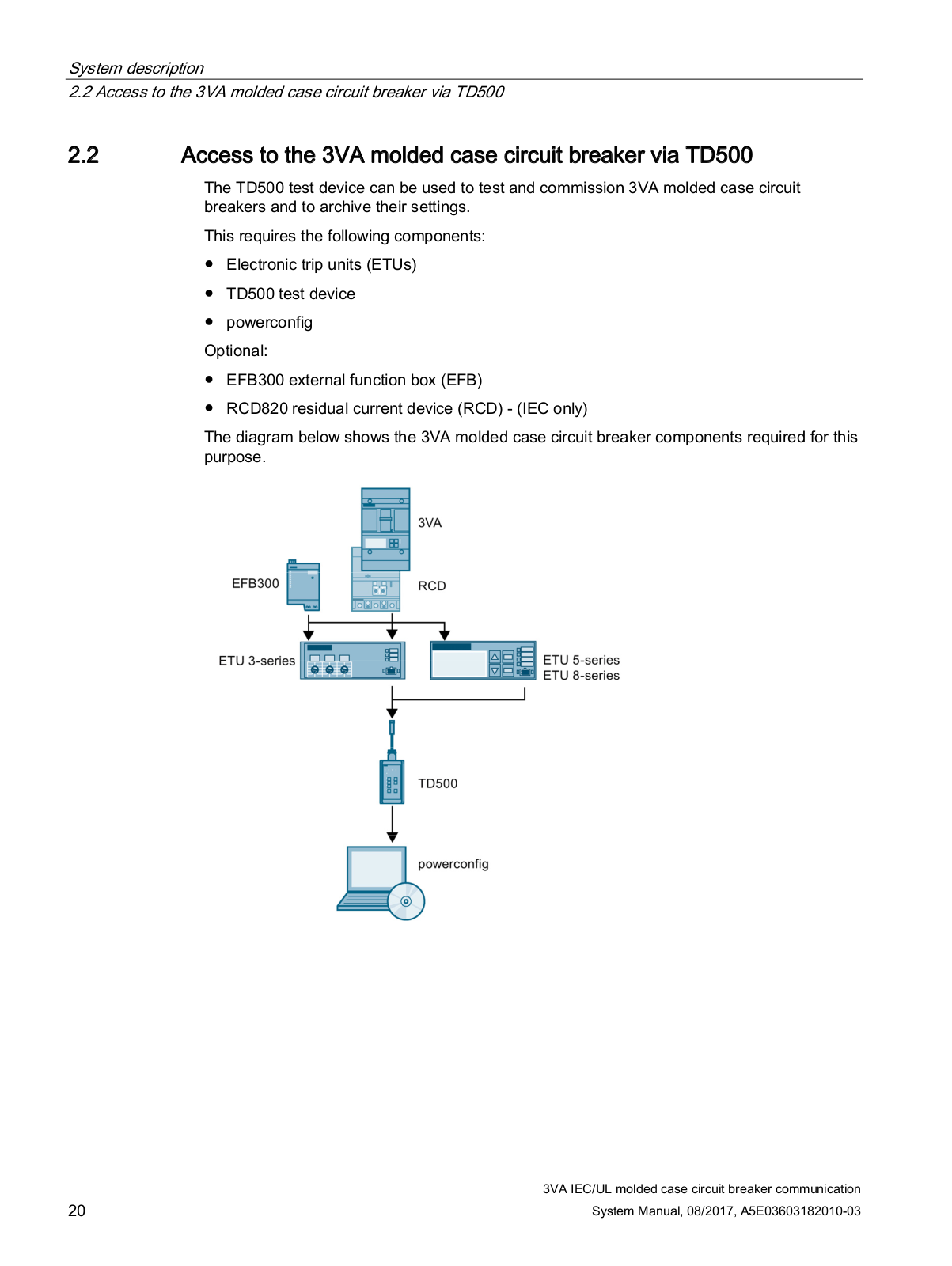
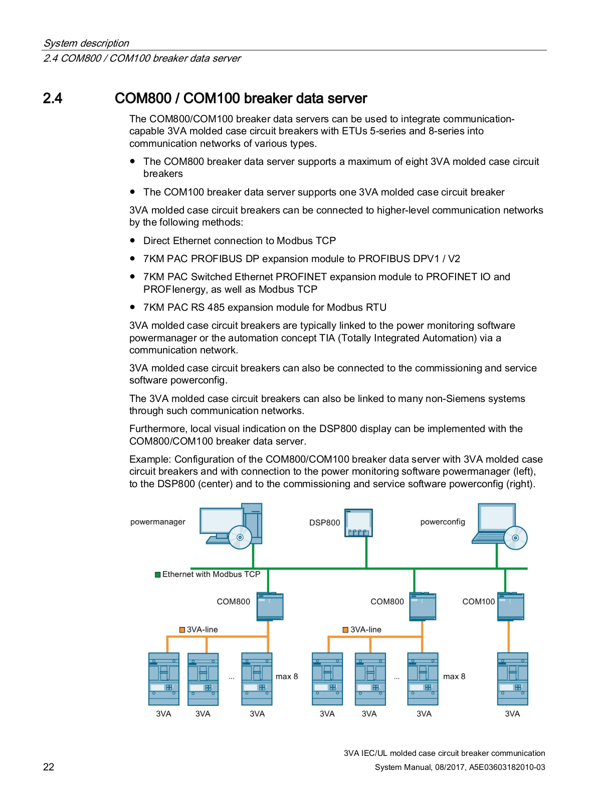
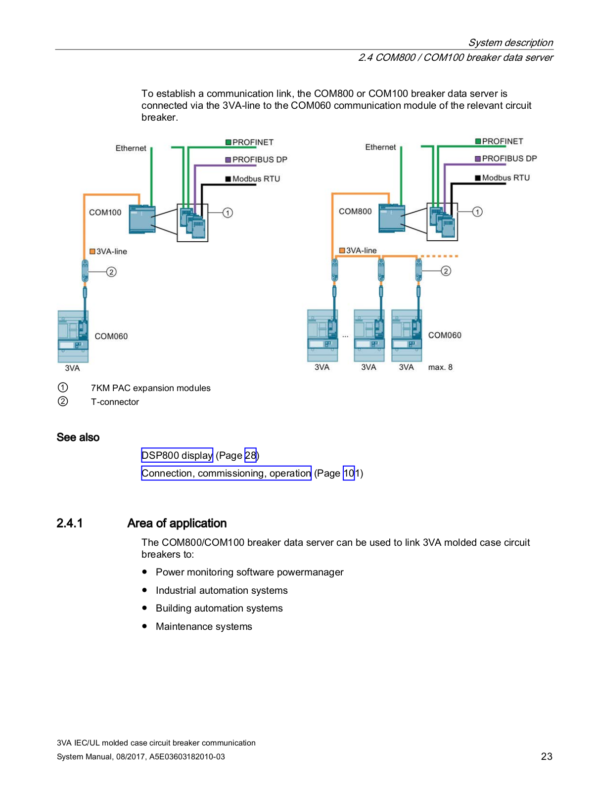
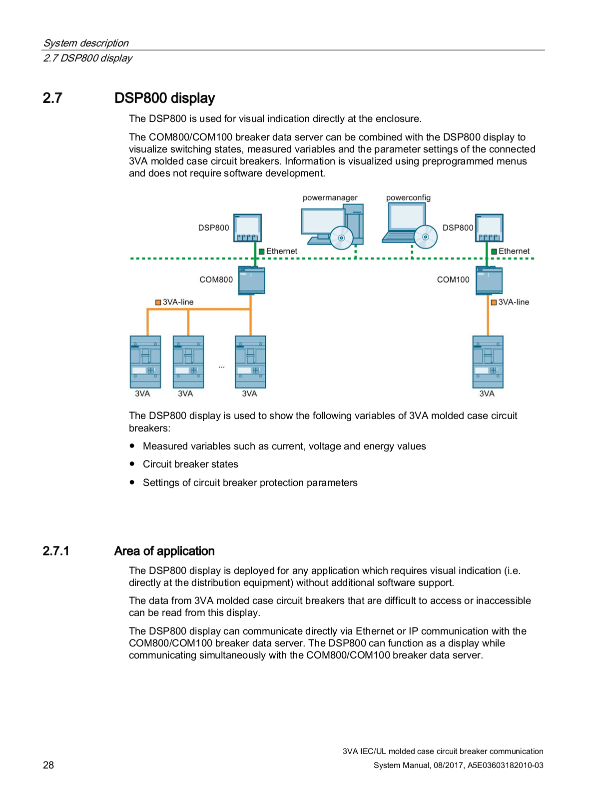
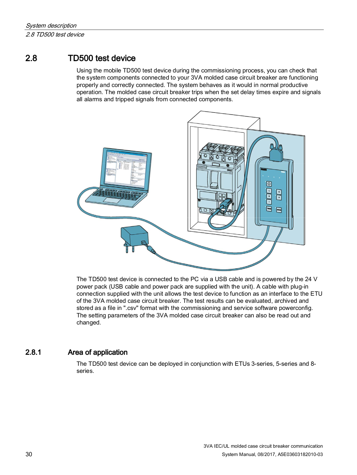
Siemens SENTRON System Manual
...
Siemens System Manual
Download
Specifications and Main Features
Frequently Asked Questions
User Manual
Download
Loading...
+
hidden pages
Unhide
You need points to download manuals.
1 point = 1 manual.
You can buy points or you can get point for every manual you upload.
Buy points
Upload your manuals
 Loading...