

Page 1
SiemensSchmitt
Sensation
Maintenance Protocol
System
Maintenance Protocol System
Customer:
Address:
CT
Fax / E-Mail:
Fax / E-Mail:
Department: Room:
Material-No.: Serial-No.:
Contract-No.: Expire date:
Order-No.: System - ID:
The instructions CT02-023.831.01.20.02 are required for
this protocol
Print No.:
Replaces: CT02-023.832.01.19.02
073931140754198507543015075431060809895108377520088720170887442710017857101300401035125510351301
CT02-023.832.01.20.02
© Siemens
The reproduction, transmission or use
of this document or its contents is not
permitted without express written
authority. Offenders will be liable for
damages. All rights, including rights
created by patent grant or registration
of a utility model or design, are
reserved.
English
Doc. Gen. Date: 10.09
2005
Page 2
Protocol Date: Serial-No.:
1Protocol
Evaluating the Condition of the System / Component 0
The system / component has no deficiencies. The image quality
test resulted in no differences from required reference values.
The system / component has slight deficiencies that have no affect
on continued operation of the system. However they should be
corrected preventively. The image quality test resulted in no differences from required reference values.
The system / component has serious deficiencies. For safety reasons, continued operation of the system is permitted only after
successfully correcting the deficiencies.
After completing all work steps, an evaluation was performed.
Signature:
Date: Name:
The customer or a representative has taken note of the assessment of the
system condition (only if required in the country).
Signature:
Date: Name:
Remarks
e.g. Additional activities to be performed, customer wishes
Further Processing and Archiving of the Protocol
The protocol is a document and thus must be archived. After completing the test, it must
be filed in the corresponding register in the “System Owner Manual“ binder.
Sensation CT02-023.832.01.20.02 Siemens
10.09 H WS CS SD CT
Page 2 of 14
Page 3
Protocol Date: Serial-No.:
Remarks Regarding the Protocol 1.1
The protocol is valid as proof of quality for one check that must be performed on the system
/ component.
The check must be performed in the specified intervals.
The results of the check are entered in this protocol.
The chapter numbers in front of the checkpoints indicate the corresponding chapters in the
particular instructions (see cover page).
The protocol must be completely filled out by the Customer Service Engineer, i.e.:
• All boxes must be filled out. If a box does not apply to the system or if no entry needs to
be made, check the “n.a.“ box.
• Enter the Serial no.: and the date of the check in the header of each page so that each
page can be allocated to a check date.
• The measurement values for the measurements that must be performed during the
check must also be entered in the open spaces / tables provided for them.
• After completing the check, Page 2 of this protocol must be filled out and signed.
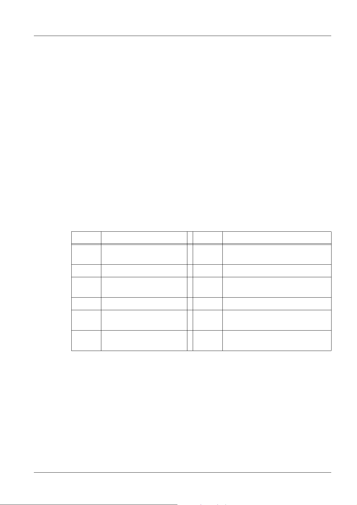
Explanation of Abbreviations in the Protocol 0
Abbrev. Explanation Abbrev. Explanation
SI Safety Inspection PMF Preventive Maintenance, Operating
Value Check, Function Check
SIE Electrical Safety Inspection Q System Quality, Image Quality
SIM Mechanical Safety Inspec-
tion
PM Preventive Maintenance QSQ System Quality Check
PMP Periodic Preventive Mainte-
nance
PMA Preventive Maintenance
Adjustments
QIQ Image Quality
SW Software Maintenance
CSE Customer Service Engineer
Siemens CT02-023.832.01.20.02 Sensation
10.09 H WS CS SD CT
Page 3 of 14
Page 4

Protocol Date: Serial-No.:
Measuring Equipment and Measuring Instruments Used 1.2
Measuring instruments and measuring devices (phantoms, MR coils etc.) may not be
entered in the table if they have already been entered in the mobile device.
Measuring equipment / -instruments Serial No. Date used
Sensation CT02-023.832.01.20.02 Siemens
10.09 H WS CS SD CT
Page 4 of 14
Page 5

Protocol Date: Serial-No.:
1 General
2 Prerequisites
2.1 Required tools and auxiliary materials
2.2 Evaluating Reports
PM Checking system reports
2.3 Evaluating the logbook
PM Error statistics readout
3 Safety Inspections
3.1 General
3.2 Function Tests
OK not n.a.
OK
3.2.1 Measuring the patient leakage current (DIN VDE 751-1)
SI Patient leakage current checked
3.2.2 Checking the protective ground conductor resistance
3.2.3 Checking the function of the door contact switch
SI Door contact switch checked
3.2.4 System: Checking the radiation preparation indicator
SI Radiation preparation indicators checked
3.2.5 System: Checking the radiation indicator
SI Radiation indicators checked
3.2.6 System: Checking the radiation monitor (108%)
SI Radiation switch-off checked
Measured value:
3.2.7 System: Checking the emergency STOP circuit
SI Emergency STOP circuit checked
3.2.8 Gantry: Checking the tube cooling hoses
SI Tube cooling hoses checked
3.2.9 PHS: Checking the safety switches
SI Safety limit switches checked
3.2.10 PHS: Checking the spindle brake
SI Function of spindle brake checked
3.2.11 PHS: Checking the motor brake
SI Function of motor brake checked
Siemens CT02-023.832.01.20.02 Sensation
10.09 H WS CS SD CT
Page 5 of 14
Page 6

Protocol Date: Serial-No.:
3.2.12 PHS: Checking the patient positioning aids
SI Patient positioning aids checked
3.2.13 PDC: Protection functionality test
SI Circuit breaker checked
Maintenance of this section was performed by:
Signature:
Date: Name:
3.3 Next steps
3.3.1 Labels
3.3.2 Concluding test
Q Condition of the CT system checked
Maintenance of this section was performed by:
OK not n.a.
OK
Signature:
Date: Name:
4 Preventive maintenance (part 1)
4.1 General
4.1.1 Preparations
4.1.2 Required tools and auxiliary materials
4.2 Patient handling system
4.2.1 Lubricating the spindle nut
PM Spindle nut lubricated
4.2.2 Lubricating the linear guides on the lower part of scissor mechanism
PM Lower part of the scissor mechanism: Linear guides lubricated
4.2.3 Lubricating the linear guides of the upper part of scissor mechanism
PM Upper part of the scissor: Linear guides lubricated
4.2.4 Lubricating the guide rails of the tabletop
PM Tabletop: Guide rails lubricated
4.2.5 Lubricating the guide rails of the top support
PM Top support: Guide rails lubricated
4.2.6 Checking the movement of the tabletop
PM Movement force for horizontal tabletop travel checked
Sensation CT02-023.832.01.20.02 Siemens
10.09 H WS CS SD CT
Page 6 of 14
Page 7

Protocol Date: Serial-No.:
4.2.7 Checking the movement of the top support
PM Movement force for horizontal top support travel checked.
4.2.8 Checking the compression spring on the patient table
PM Compression spring checked
4.2.9 Cleaning the motor brake of the couch lift motor
PM Vertical motor brake cleaned
Maintenance of this section was performed by:
Signature:
Date: Name:
4.3 Next steps
4.3.1 Concluding test
Q Condition of the CT system checked
OK not n.a.
OK
Maintenance of this section was performed by:
Signature:
Date: Name:
5 Preventive maintenance (part 2)
5.1 General
5.1.1 Preparations
5.1.2 Required tools and auxiliary materials
5.2 Care Vision (Option)
5.2.1 Checking the weight compensation of the support arm
SI Weight compensation of the support arm checked
Siemens CT02-023.832.01.20.02 Sensation
10.09 H WS CS SD CT
Page 7 of 14
Page 8

Protocol Date: Serial-No.:
5.3 Sliding gantry (optional)
PM Check the toothed belt
PM Cleaning the energy chain (every 3 years)
PM Check the switching elements (front and rear)
PM Check the blind covering (optional)
PM Check the protective conductor connection
Maintenance of this section was performed by:
Signature:
Date: Name:
5.4 Gantry
5.4.1 Functional check of the fans in the generator electronic box
SI Function of E-box fans checked
5.4.2 Functional check of the HV transformer fans
SI Function of HV transformer fans checked
OK not n.a.
OK
5.4.3 Functional check of the C-box fans (only Sensation 10 / 16 / Cardiac)
SI Function of C-box fan checked
5.4.4 Functional check of the DMS fans
SI Function of DMS fans checked
5.4.5 Cleaning the slip ring compartment
PM Slip ring compartment and assembly cleaned
5.4.6 Cleaning/checking the power brush block
PM Power brush block cleaned
PM Power carbon brushes checked
Startup Date: . .
Date of Last Replacement
: DD MMM YYYY
5.4.7 Checking/replacing the voltage and control data brushes
PM Voltage and control data brushes checked
PM Control data brushes replaced
Startup Date: . .
Date of Last Replacement
Sensation CT02-023.832.01.20.02 Siemens
10.09 H WS CS SD CT
: DD MMM YYYY
Page 8 of 14
Page 9

Protocol Date: Serial-No.:
5.4.8 Replacing the stator ring brush (only Sensation 10 / 16 / Cardiac)
PM Stator ring brush replaced
Startup Date: . .
OK not n.a.
OK
Date of Last Replacement
: DD MMM YYYY
5.4.9 Lubricating the rack and pinion gear of the UHR assembly (only Sensation 64, Cardiac 64)
PM Rack and pinion gear lubricated (only Sensation 64, Cardiac 64, not
UHR-Plus)
5.4.10 Cleaning/checking the detector window
PM Detector window cleaned/checked
Startup Date: . .
Date of Last Replacement
: DD MMM YYYY
5.4.11 Lubricating the main bearing
PM Main bearing lubricated
5.4.12 Replacing the filter in the dehumidifier
PM Filter in Dehumidifier replaced
Startup Date: . .
Date of Last Replacement
: DD MMM YYYY
Maintenance of this section was performed by:
Signature:
Date: Name:
5.5 Power distribution cabinet
5.5.1 Replacing the air filter
PM Air filter in PDC replaced
Startup Date: . .
Date of Last Replacement
: DD MMM YYYY
Siemens CT02-023.832.01.20.02 Sensation
10.09 H WS CS SD CT
Page 9 of 14
Page 10

Protocol Date: Serial-No.:
5.5.2 Checking/replacing the varistors and discharger
PM Varitors / discharger checked/replaced
Startup Date: . .
OK not n.a.
OK
Date of Last Replacement
: DD MMM YYYY
Maintenance of this section was performed by:
Signature:
Date: Name:
5.6 Water cooling system
5.6.1 Checking the water pressure
PM Water pressure checked
Measured value:
5.6.2 Cleaning the filter in the water-air cooling system
PM Filter cleaned
Maintenance of this section was performed by:
Signature:
Date: Name:
5.7 Imaging system
5.7.1 Cleaning the ICS, IRS and IES
PM Air inlets of ICS, and IES cleaned
PM Air inlets of IRS and air filters are cleaned
PM IRS air filter replaced
Startup Date: . .
Date of Last Replacement
Maintenance of this section was performed by:
Date: Name:
: DD MMM YYYY
Signature:
Sensation CT02-023.832.01.20.02 Siemens
10.09 H WS CS SD CT
Page 10 of 14
Page 11

Protocol Date: Serial-No.:
5.8 SRS Check
5.8.1 Work Steps for Som/7 VA11 and Som/5 VB30/VB38
5.8.1.1 Checking the status of the SRS installation (check only!)
PM Checking the status of the SRS installation
5.8.1.2 Checking the System Management Configuration
PM Checking the System Management Configuration
5.8.2 Work Steps for Som/5 VB20/VB28
5.8.2.1 Checking the status of the SRS network connection (check only!)
PM Checking the status of the SRS network connection
5.8.2.2 Checking the System Management Configuration
PM Checking the System Management Configuration
5.9 Next steps
5.9.1 Concluding test
Q Condition of the CT system checked
OK not n.a.
OK
Maintenance of this section was performed by:
Signature:
Date: Name:
6 Preventive parts replacement
6.1 General
6.1.1 Preparations
6.1.2 Required tools and auxiliary materials
6.2 Uninterrupted power supply
6.2.1 Prerequisites
6.2.2 Replacing the standard UPS
PM UPS replaced
Startup Date: . .
Date of Last Replacement
: DD MMM YYYY
Maintenance of this section was performed by:
Signature:
Date: Name:
Siemens CT02-023.832.01.20.02 Sensation
10.09 H WS CS SD CT
Page 11 of 14
Page 12

Protocol Date: Serial-No.:
6.3 DMS cover Sensation 10 / 16 / Sensation Cardiac
6.3.1 Prerequisites
6.3.2 Check the correct attachment of the lead sheet metal.
PM DMS cover replaced
Startup Date: . .
OK not n.a.
OK
Date of Last Replacement
Maintenance of this section was performed by:
Date: Name:
6.4 Next steps
6.4.1 Concluding test
Q Condition of the CT system checked
Maintenance of this section was performed by:
Date: Name:
: DD MMM YYYY
Signature:
Signature:
7 Image quality - constancy
Q Image quality check completed
Maintenance of this section was performed by:
Signature:
Date: Name:
8 Final steps
8.1 Installing the unit covers
SIM Covers and protective conductor cables are installed
Sensation CT02-023.832.01.20.02 Siemens
10.09 H WS CS SD CT
Page 12 of 14
Page 13

Protocol Date: Serial-No.:
OK not n.a.
8.2 Checking the protective system conductor
8.3 General notes when measuring at the monitors
8.3.1 Measuring point 18” monitor
8.3.2 Measuring point 19” monitor
8.4 SOMATOM Sensation 10 / 16 / Cardiac / 40 / 64 / Cardiac 64 / Open
SIE PDC Cabinet: Protective conductor resistance ≤ 100 mΩ
Measured value:
SIE Gantry: Protective conductor resistance ≤ 300 mΩ
Measured value:
SIE Patient table (PHS): Protective conductor resistance ≤ 300 mΩ
Measured value:
OK
SIE ICS Tower PC: Protective conductor resistance ≤ 300 mΩ
Measured value:
SIE IRS Cabinet: Protective conductor resistance ≤ 300 mΩ
Measured value:
SIE IES Tower PC: Protective conductor resistance ≤ 300 mΩ
Measured value:
SIE ICS Monitor: Protective conductor resistance ≤ 300 mΩ
Measured value:
SIE IES Monitor: Protective conductor resistance ≤ 300 mΩ
Measured value:
SIE WCS Cabinet: Protective conductor resistance (mains connected
directly) ≤ 100 mΩ Protective conductor resistance (connected via PDC)
≤ 300 mΩ
Measured value:
SIE UPS IES: Protective conductor resistance ≤ 100 mΩ
Measured value:
Siemens CT02-023.832.01.20.02 Sensation
10.09 H WS CS SD CT
Page 13 of 14
Page 14

Protocol Date: Serial-No.:
SIE IES Tower PC: Protective conductor resistance ≤ 300 mΩ
Measured value:
8.5 CARE Vision CT option
SIE Overhead support: Protective conductor resistance ≤ 300 mΩ
Measured value:
SIE Monitor trolley: Protective conductor resistance ≤ 300 mΩ
Measured value:
SIE Monitor: Protective conductor resistance ≤ 300 mΩ
Measured value:
8.6 Cleaning the monitors
SIM Monitors cleaned
OK not n.a.
OK
8.7 Testing the system application
Q Condition of the CT system checked
Maintenance of this section was performed by:
Signature:
Date: Name:
9 Changes to previous Version
Sensation CT02-023.832.01.20.02 Siemens
10.09 H WS CS SD CT
Page 14 of 14
 Loading...