

Siemens SCALANCE XM-400,SIMATIC NET SCALANCE XM-400 Operating Instructions Manual

SCALANCE XM-400
___________________
___________________
___________________
___________________
___________________
___________________
___________________
___________________
___________________
SIMATIC NET
Industrial Ethernet switches
SCALANCE XM-400
Operating Instructions
05/2014
C79000
Introduction
Safety notices
1
Description of the device
2
Installation
3
Connecting up
4
Upkeep and maintenance
5
Technical specifications
6
Dimension drawings
7
Approvals
A
-G8976-C306-03
Siemens AG
Industry Sector
Postfach 48 48
90026 NÜRNBERG
GERMANY
C79000-G8976-C306-03
Ⓟ
Copyright © Siemens AG 2013 - 2014.
All rights reserved
Legal information
Warning notice system
DANGER
indicates that death or severe personal injury will result if proper precautions are not taken.
WARNING
indicates that death or severe personal injury may result if proper precautions are not taken.
CAUTION
indicates that minor personal injury can result if proper precautions are not taken.
NOTICE
indicates that property damage can result if proper precautions are not taken.
Qualified Personnel
personnel qualified
Proper use of Siemens products
WARNING
Siemens products may only be used for the applications described in the catalog and in the relevant technical
Trademarks
Disclaimer of Liability
This manual contains notices you have to observe in order to ensure your personal safety, as well as to prevent
damage to property. The notices referring to your personal safety are highlighted in the manual by a safety alert
symbol, notices referring only to property damage have no safety alert symbol. These notices shown below are
graded according to the degree of danger.
If more than one degree of danger is present, the warning notice representing the highest degree of danger will
be used. A notice warning of injury to persons with a safety alert symbol may also include a warning relating to
property damage.
The product/system described in this documentation may be operated only by
task in accordance with the relevant documentation, in particular its warning notices and safety instructions.
Qualified personnel are those who, based on their training and experience, are capable of identifying risks and
avoiding potential hazards when working with these products/systems.
for the specific
Note the following:
documentation. If products and components from other manufacturers are used, these must be recommended
or approved by Siemens. Proper transport, storage, installation, assembly, commissioning, operation and
maintenance are required to ensure that the products operate safely and without any problems. The permissible
ambient conditions must be complied with. The information in the relevant documentation must be observed.
All names identified by ® are registered trademarks of Siemens AG. The remaining trademarks in this publication
may be trademarks whose use by third parties for their own purposes could violate the rights of the owner.
We have reviewed the contents of this publication to ensure consistency with the hardware and software
described. Since variance cannot be precluded entirely, we cannot guarantee full consistency. However, the
information in this publication is reviewed regularly and any necessary corrections are included in subsequent
editions.
05/2014 Subject to change

Introduction
Purpose of the Operating Instructions
Validity of the Operating Instructions
Designations used
Classification
Description
Terms used
term SCALANCE X-400 is used.
term SCALANCE XM-400 is used.
SCALANCE XM416-4C
Documentation on configuration
These operating instructions support you when installing and connecting up devices of the
SCALANCE XM-400 product group.
The configuration and the integration of the device in a network are not described in these
operating instructions.
These operating instructions apply to the following devices:
● SCALANCE XM408-4C
● SCALANCE XM408-8C
● SCALANCE XM416-4C
Unless mentioned otherwise, the descriptions in these operating instructions refer to all
devices of the SCALANCE XM-400 product group named above in the section on validity.
Product line The product line includes all devices and variants of all product groups.
If information applies to all product groups within the product line, the
Product group If information applies to all devices and variants of a product group, the
Device If information relates to a specific device, the device name is used. SCALANCE XM408-4C
SCALANCE X-400
SCALANCE XM-400
SCALANCE XM408-8C
You will find detailed information on configuring the devices in the following configuration
manuals:
● SCALANCE XM-400/XR-500 Web Based Management
● SCALANCE XM-400/XR-500 Command Line Interface
SCALANCE XM-400
Operating Instructions, 05/2014, C79000-G8976-C306-03
3

Introduction
Further documentation
SIMATIC NET manuals
You will find the configuration manuals here:
● On the data medium that ships with some products:
– Product CD / product DVD
– SIMATIC NET Manual Collection
● On the Internet pages of Siemens Industry Online Support.
(http://support.automation.siemens.com/WW/view/en/79730528/130000
)
In the system manuals "Industrial Ethernet / PROFINET Industrial Ethernet" and "Industrial
Ethernet / PROFINET passive network components", you will find information on other
SIMATIC NET products that you can operate along with the devices of this product line in an
Industrial Ethernet network.
There, you will find among other things optical performance data of the communications
partner that you require for the installation.
You will find the system manuals here:
● On the data medium that ships with some products:
– Product CD / product DVD
– SIMATIC NET Manual Collection
● On the Internet pages of Siemens Industry Online Support under the following entry IDs:
– 27069465 (http://support.automation.siemens.com/WW/view/en/27069465
– 84922825 (http://support.automation.siemens.com/WW/view/en/84922825)
You will find SIMATIC NET manuals on the Internet pages of Siemens Industry Online
Support:
● using the search function:
Link to Siemens Industry Online Support
(http://support.automation.siemens.com/WW/view/en
Enter the entry ID of the relevant manual as the search item.
● In the navigation panel on the left hand side in the area "Industrial Communication":
Link to the area "Industrial Communication"
(http://support.automation.siemens.com/WW/view/en/10805878/130000
)
Industrial Ethernet / PROFINET Industrial Ethernet System Manual
Industrial Ethernet / PROFINET - Passive network components System Manual
)
)
Go to the required product group and make the following settings:
tab "Entry list", Entry type "Manuals"
SCALANCE XM-400
4 Operating Instructions, 05/2014, C79000-G8976-C306-03

Introduction
SIMATIC NET glossary
Catalogs
You will find the documentation for the SIMATIC NET products relevant here on the data
medium that ships with some products:
● Product CD / product DVD
● SIMATIC NET Manual Collection
Explanations of many of the specialist terms used in this documentation can be found in the
SIMATIC NET glossary.
You will find the SIMATIC NET glossary here:
● SIMATIC NET Manual Collection or product DVD
The DVD ships with certain SIMATIC NET products.
● On the Internet under the following entry ID:
50305045 (http://support.automation.siemens.com/WW/view/en/50305045
)
You will find the order numbers for the Siemens products of relevance here in the following
catalogs:
● SIMATIC NET Industrial Communication / Industrial Identification, catalog IK PI
● SIMATIC Products for Totally Integrated Automation and Micro Automation, catalog
ST 70
● Industry Mall - catalog and ordering system for automation and drive technology, Online
catalog
https://eb.automation.siemens.com/goos/WelcomePage.aspx?regionUrl=/en&language=
(
en)
You can request the catalogs and additional information from your Siemens representative.
SCALANCE XM-400
Operating Instructions, 05/2014, C79000-G8976-C306-03
5

Introduction
Unpacking and checking
WARNING
Do not use any parts that show evidence of damage
Security information
If you use damaged parts, there is no guarantee that the device will function according to
the specification.
If you use damaged parts, this can lead to the following problems:
• Injury to persons
• Loss of the approvals
• Violation of the EMC regulations
• Damage to the device and other components
Use only undamaged parts.
1. Make sure that the package is complete.
2. Check all the parts for transport damage.
Siemens provides products and solutions with industrial security functions that support the
secure operation of plants, solutions, machines, equipment and/or networks. They are
important components in a holistic industrial security concept. With this in mind, Siemens’
products and solutions undergo continuous development. Siemens recommends strongly
that you regularly check for product updates.
For the secure operation of Siemens products and solutions, it is necessary to take suitable
preventive action (e.g. cell protection concept) and integrate each component into a holistic,
state-of-the-art industrial security concept. Third-party products that may be in use should
also be considered. For more information about industrial security, visit
http://www.siemens.com/industrialsecurity
To stay informed about product updates as they occur, sign up for a product-specific
newsletter. For more information, visit http://support.automation.siemens.com
.
.
SCALANCE XM-400
6 Operating Instructions, 05/2014, C79000-G8976-C306-03

Table of contents
Introduction ................................................................................................................................................ 3
1 Safety notices ............................................................................................................................................ 9
2 Description of the device ......................................................................................................................... 11
3 Installation ............................................................................................................................................... 35
2.1 Product group............................................................................................................................... 11
2.2 Product overview ......................................................................................................................... 12
2.3 Accessories .................................................................................................................................. 14
2.4 Spare parts ................................................................................................................................... 16
2.5 Views ............................................................................................................................................ 17
2.5.1 View of a SCALANCE XM408-4C................................................................................................ 17
2.5.2 View of a SCALANCE XM408-8C device .................................................................................... 18
2.5.3 View of a SCALANCE XM416-4C device .................................................................................... 19
2.6 SELECT / SET button .................................................................................................................. 20
2.7 LED display .................................................................................................................................. 23
2.7.1 Overview ...................................................................................................................................... 23
2.7.2 "RM" LED ..................................................................................................................................... 23
2.7.3 "SB" LED ...................................................................................................................................... 24
2.7.4 "F" LED ........................................................................................................................................ 24
2.7.5 LEDs "DM1" and "DM2" ............................................................................................................... 25
2.7.6 LEDs "L1" and "L2" ...................................................................................................................... 26
2.7.7 Port LEDs ..................................................................................................................................... 27
2.8 C-PLUG/KEY-PLUG .................................................................................................................... 29
2.8.1 Function of the C-PLUG/KEY-PLUG ........................................................................................... 29
2.8.2 Replacing the C-PLUG/KEY-PLUG ............................................................................................. 30
2.9 Functions ...................................................................................................................................... 32
2.9.1 Combo ports ................................................................................................................................. 32
2.9.2 Power over Ethernet (PoE) ..........................................................................................................
3.1 Safety notices for installation ....................................................................................................... 35
3.2 Types of installation ..................................................................................................................... 37
3.3 Mounting on DIN rails .................................................................................................................. 37
3.4 Installation on a standard S7-300 rail .......................................................................................... 39
33
3.5 Installation on a standard S7-1500 rail ........................................................................................ 40
3.6 Fitting an extender ....................................................................................................................... 41
3.7 General notes for SFP transceivers ............................................................................................. 44
SCALANCE XM-400
Operating Instructions, 05/2014, C79000-G8976-C306-03
7

Table of contents
4 Connecting up ......................................................................................................................................... 45
5 Upkeep and maintenance ........................................................................................................................ 57
6 Technical specifications ........................................................................................................................... 59
7 Dimension drawings ................................................................................................................................ 67
A Approvals ................................................................................................................................................. 73
Index ........................................................................................................................................................ 79
4.1 Safety when connecting up ......................................................................................................... 45
4.2 Spring-loaded terminal ................................................................................................................ 47
4.3 Power supply ............................................................................................................................... 47
4.4 Signaling contact ......................................................................................................................... 49
4.5 Serial interface ............................................................................................................................ 51
4.6 Out-of-band interface .................................................................................................................. 53
4.7 Near Field Communication .......................................................................................................... 54
4.8 Functional ground ....................................................................................................................... 55
5.1 Downloading new firmware using TFTP without WBM and CLI ................................................. 57
5.2 Restoring the factory settings...................................................................................................... 58
6.1 Technical specifications of the SCALANCE XM408-4C ............................................................. 59
6.2 Technical specifications of the SCALANCE XM408-8C ............................................................. 61
6.3 Technical specifications of the SCALANCE XM416-4C ............................................................. 63
6.4 Switching properties .................................................................................................................... 65
7.1 SCALANCE XM-400 dimension drawings .................................................................................. 67
7.2 Extender dimension drawings ..................................................................................................... 70
A.1 FDA and IEC marks .................................................................................................................... 77
A.2 Mechanical stability (in operation) ............................................................................................... 77
SCALANCE XM-400
8 Operating Instructions, 05/2014, C79000-G8976-C306-03
1
Read the safety notices
Safety notices on use in hazardous areas
General safety notices relating to protection against explosion
WARNING
EXPLOSION HAZARD
Safety notices when using the device according to Hazardous Locations (HazLoc)
Note the following safety notices. These relate to the entire working life of the device.
You should also read the safety notices relating to handling in the individual sections,
particularly in the sections "Installation" and "Connecting up".
DO NOT OPEN WHEN ENERGIZED.
If you use the device under HazLoc conditions you must also keep to the following safety
notices in addition to the general safety notices for protection against explosion:
This equipment is suitable for use in Class I, Division 2, Groups A, B, C and D or nonhazardous locations only.
This equipment is suitable for use in Class I, Zone 2, Group IIC or non-hazardous locations
only.
SCALANCE XM-400
Operating Instructions, 05/2014, C79000-G8976-C306-03
9

Safety notices
SCALANCE XM-400
10 Operating Instructions, 05/2014, C79000-G8976-C306-03

2
2.1
Product group
SCALANCE XM-400 product group
SCALANCE XM-400 basic device
Basic properties
Expansions
The product group SCALANCE XM-400 consists of basic devices (compact switches) and
extenders (port extenders).
The SCALANCE XM-400 basic devices are modular compact switches with fixed RJ-45
ports (10/100/1000 Mbps) and SFP transceiver slots that can be equipped individually. The
SFP transceiver slots are combo ports.
A SCALANCE XM-400 can manage a maximum of 24 ports with 10/100/1000 Mbps.
The following components exist only on the basic device:
● CPU
● Power supply
● Signaling contact
● Out-of-band port
● Serial interface
● "SELECT / SET" button
The basic devices can be expanded with additional ports by using an extender. The
extenders are connected to the side of the basic device. Each basic device has an
expansion interface on the right for port extenders.
Depending on the number of ports of the basic device (10/100/1000 Mbps) up to 2 port
extenders can be added. Further port extenders are not supplied with power. There is no
particular order in which the port extenders need to be added.
Example
● The basic device SCALANCE XM408-8C has 8 ports. It can therefore be expanded by 2
port extenders each with 8 ports.
● The basic device SCALANCE XM416-4C has 16 ports. It can therefore be expanded by
one port extender with 8 ports.
SCALANCE XM-400
Operating Instructions, 05/2014, C79000-G8976-C306-03
11
Description of the device
Port extender (PE400)
Note
Port extenders function only in conjunction with a basic device.
2.2
Product overview
Order numbers
Device
Description
Order number
extenders, layer 3 with KEY-PLUG
extenders, layer 3 integrated
extenders, layer 3 with KEY-PLUG
extenders, layer 3 integrated
extender, layer 3 with KEY-PLUG
extender, layer 3 integrated
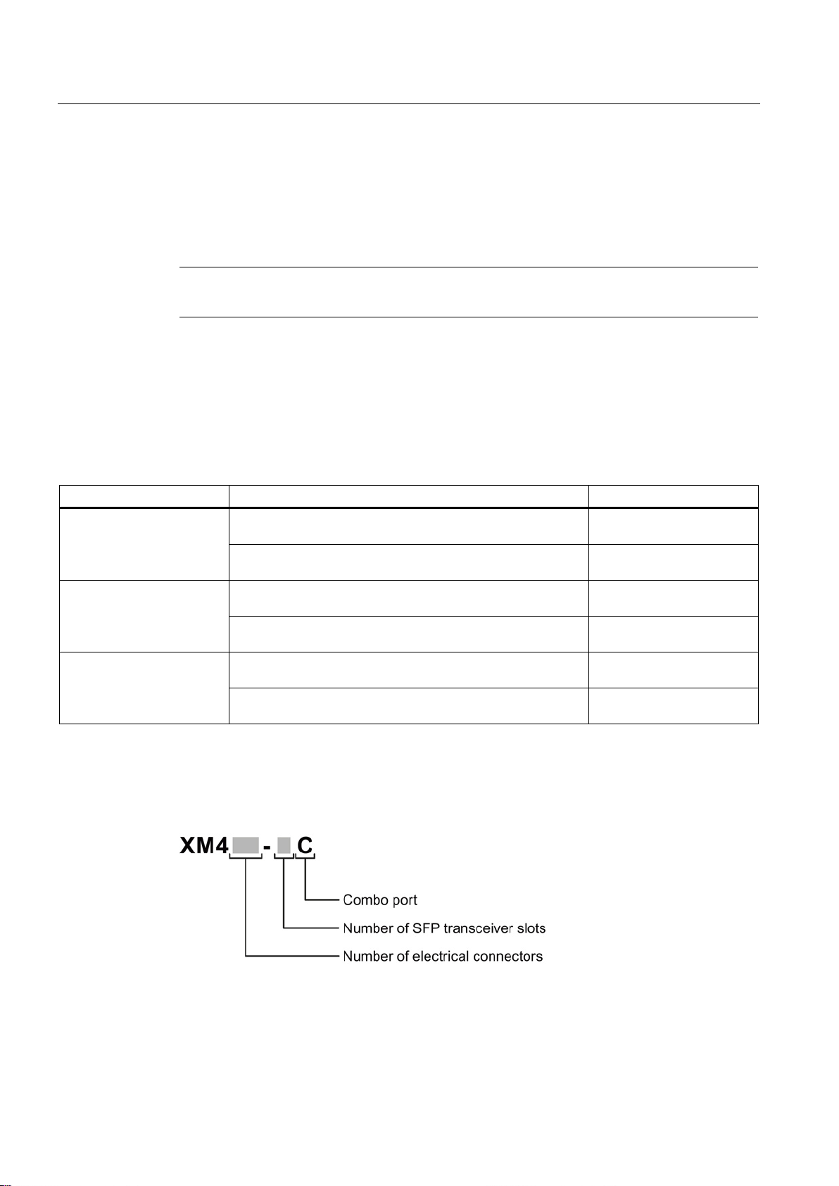
Type designation
2.2 Product overview
Port extenders are modular network components with RJ-45 ports (10/100/1000 Mbps) or
SFP transceiver slots. To the left they have an expansion interface to connect to the basic
device or to another port extender and to the right they have an expansion interface for
additional port extenders. Each port extender functions with every basic device.
SCALANCE XM408-4C 8 RJ-45 ports, 4 pluggable transceiver slots, up to 2 port
8 RJ-45 ports, 4 pluggable transceiver slots, up to 2 port
SCALANCE XM408-8C 8 RJ-45 ports, 8 pluggable transceiver slots, up to 2 port
8 RJ-45 ports, 8 pluggable transceiver slots, up to 2 port
SCALANCE XM416-4C 16 RJ-45 ports, 4 pluggable transceiver slots, max. 1 port
16 RJ-45 ports, 4 pluggable transceiver slots, max. 1 port
The type designation of a SCALANCE XM-400 is made up of several parts that have the
following meaning:
6GK5 408-4GP00-2AM2
6GK5 408-4GQ00-2AM2
6GK5 408-8GS00-2AM2
6GK5 408-8GR00-2AM2
6GK5 416-4GS00-2AM2
6GK5 416-4GR00-2AM2
SCALANCE XM-400
12 Operating Instructions, 05/2014, C79000-G8976-C306-03

Description of the device
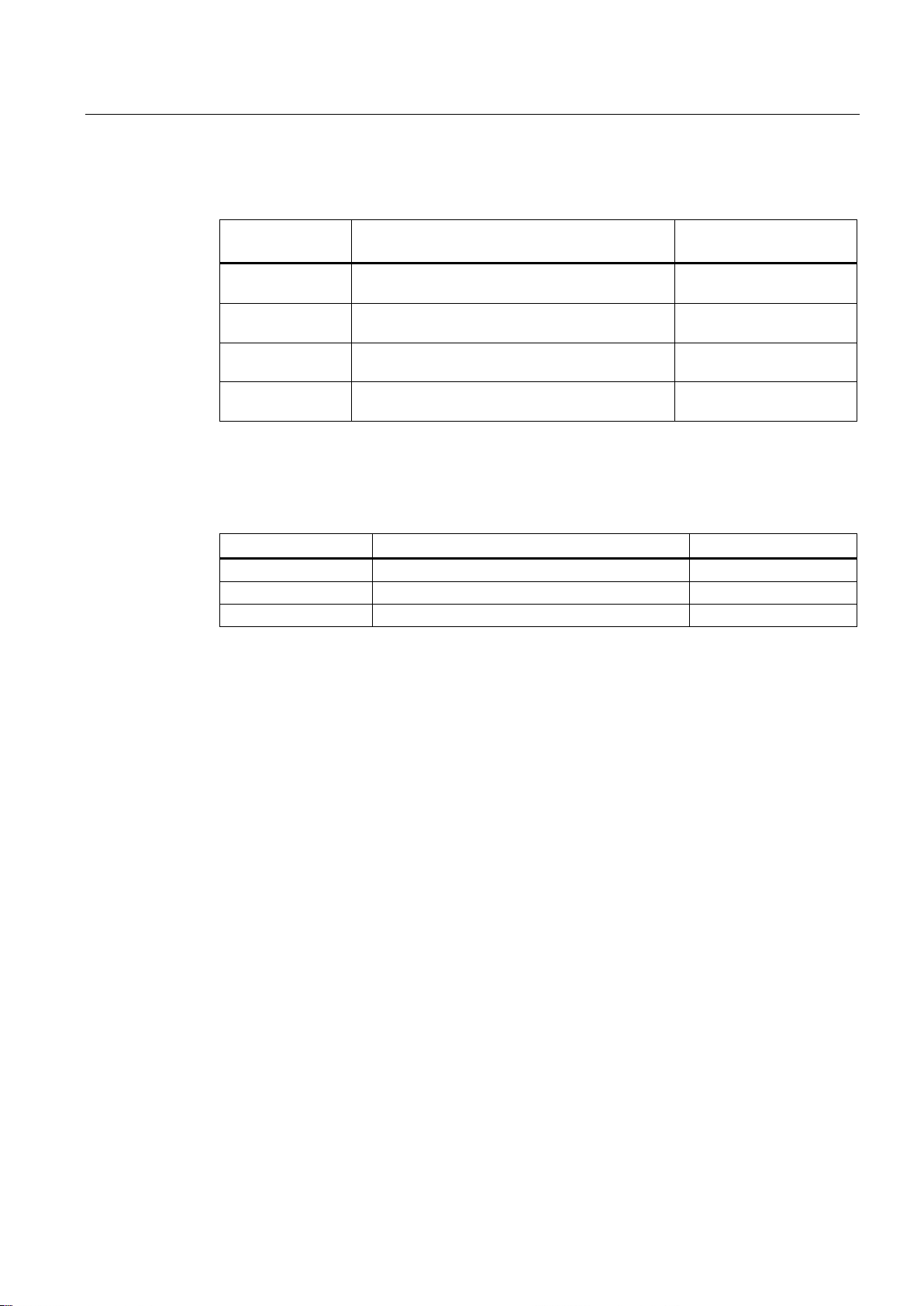
Interfaces
Device
Number of electrical
connectors
Number of combo ports
Number of slots for pluggable
transceivers
SCALANCE XM408-4C
8 4 4
SCALANCE XM408-8C
8 8 8
SCALANCE XM416-4C
16 4 4
Components of the product
2.2 Product overview
The following components are supplied with a SCALANCE XM-400:
● One device with exchangeable storage medium C-PLUG
● One product DVD with documentation and software
● Securing screw for mounting on an S7 standard rail
● A 4-pin terminal block for the power supply (spring-loaded terminal)
● A 2-pin terminal block for the signaling contact (spring-loaded terminal)
● A connecting cable for the serial interface with RJ-11 plug and 9-pin D-sub female
connector
SCALANCE XM-400
Operating Instructions, 05/2014, C79000-G8976-C306-03
13

Description of the device
2.3
Accessories
KEY-PLUG
Type
Order number
KEY-PLUG XM400 Layer 3
6GK5 904-0PA00
SFP transceiver
Type
Property
Order number
(multimode), up to max. 5 km
(single mode) up to max. 26 km
(single mode) up to max. 70 km
(single mode) up to max. 200 km
(multimode), up to max. 750 m
(single mode) up to max. 10 km
(single mode) up to max. 40 km
(single mode) up to max. 120 km
Note
Restriction for pluggable transceivers
The maximum ambient temperature changes if you use pluggable transceivers:
•
•
transceivers of the types LH, LH+, ELH or ELH200 in
For the values of the ambient temperature without pluggable transceivers, refer to the
section "
2.3 Accessories
The following accessories are available for SCALANCE XM-400:
SFP991-1 1 x 100 Mbps, LC port optical for glass FO cable
SFP991-1LD 1 x 100 Mbps LC port optical for glass FO cable
SFP991-1LH+ 1 x 100 Mbps LC port optical for glass FO cable
SFP991-1ELH200 1 x 100 Mbps LC port optical for glass FO cable
SFP992-1 1 x 1000 Mbps, LC port optical for glass FO cable
SFP992-1LD 1 x 1000 Mbps LC port optical for glass FO cable
SFP992-1LH 1 x 1000 Mbps LC port optical for glass FO cable
SFP992-1LH+ 1 x 1000 Mbps LC port optical for glass FO cable
(single mode) up to max. 70 km
SFP992-1ELH 1 x 1000 Mbps LC port optical for glass FO cable
If you use transceivers of the types multimode and LD, the maximum ambient
temperature is reduced to 60 °C.
If you use transceivers of the types LH, LH+, ELH or ELH200, the maximum ambient
temperature is reduced to 50 °C.
You can only use up to 4 pluggable
the basic device.
Technical specifications (Page 59)".
6GK5 991-1AD00-8AA0
6GK5 991-1AF00-8AA0
6GK5 991-1AE00-8AA0
6GK5 991-1AE30-8AA0
6GK5 992-1AL00-8AA0
6GK5 992-1AM00-8AA0
6GK5 992-1AN00-8AA0
6GK5 992-1AP00-8AA0
6GK5 992-1AQ00-8AA0
SCALANCE XM-400
14 Operating Instructions, 05/2014, C79000-G8976-C306-03
Description of the device
SCP / STP transceiver
Pluggable
transceiver
Property
Order number
(multimode) up to max. 750 m
(single mode) up to max. 10 km
(multimode) up to max. 5 km
(single mode) up to max. 26 km
Port extender
Device
Property
Order number
PE408
8 x 10/100/1000 Mbps RJ-45 ports
6GK5 408-0GA00-8AP2
PE408PoE
8 x 10/100/1000 Mbps, RJ-45 ports with PoE
6GK5 408-0PA00-8AP2
PE400-8SFP
8 x 100/1000 Mbps, SFP ports
6GK5 400-8AS00-8AP2
2.3 Accessories
SCP992-1 1 x 1000 Mbps SC port optical for glass FO cable
SCP992-1LD 1 x 1000 Mbps SC port optical for glass FO cable
STP991-1 1 x 100 Mbps ST port optical for glass FO cable
STP991-1LD 1 x 100 Mbps ST port optical for glass FO cable
Can only be operated in SCP and STP slots.
6GK5 992-1AJ00-8AA0
6GK5 992-1AK00-8AA0
6GK5 991-1AB00-8AA0
6GK5 991-1AC00-8AA0
SCALANCE XM-400
Operating Instructions, 05/2014, C79000-G8976-C306-03
15

Description of the device
2.4
Spare parts
Component
Description
Order number
exchangeable storage medium for configuration data
pack of 5
pack of 5
pack of 5
2.4 Spare parts
The following spare parts are available for SCALANCE XM-400:
C-PLUG Configuration plug,
Spring-loaded terminal block,
4 terminals
Spring-loaded terminal block,
2 terminals
Securing screw Screw for mounting on an S7-1500 and S7-300 standard
Connecting cable
(RJ-11/RS-232)
4-terminal spring-loaded terminal block to connect the
power supply (24 VDC),
for SCALANCE X/W/S/M,
2-terminal spring-loaded terminal block to connect the
signaling contact (24 VDC),
for SCALANCE X/W/S/M,
rail,
for SCALANCE X/W,
preassembled, serial cable with RJ-11 and RS-323 plug,
Length: 5 m
pack of 1
6GK1 900-0AB00
6GK5 980-1DB10-0AA5
6GK5 980-0BB10-0AA5
6GK5 980-4AA00-0AA5
6GK5 980-3BB00-0AA5
SCALANCE XM-400
16 Operating Instructions, 05/2014, C79000-G8976-C306-03
Description of the device
2.5
Views
2.5.1
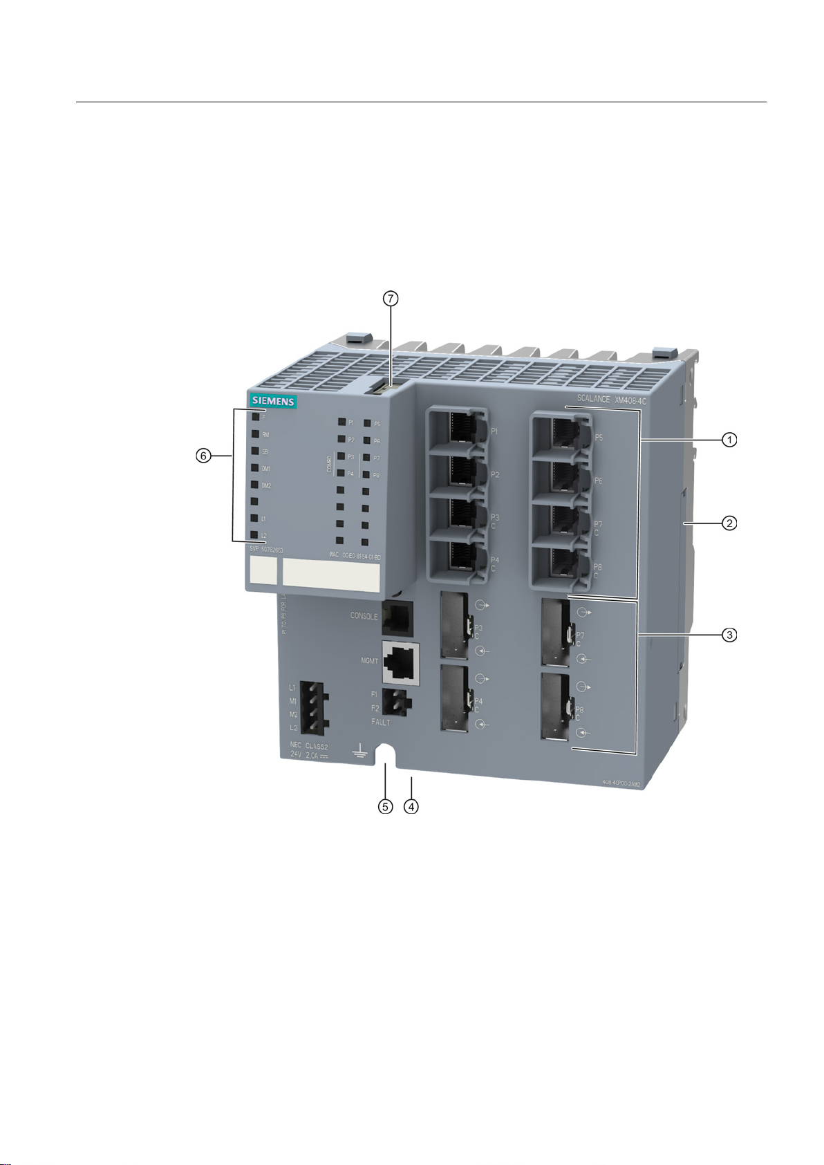
View of a SCALANCE XM408-4C
①
Electrical ports
②
Expansion interface with cover
③
Slots for pluggable transceivers (STP and DCP)
④
Location for securing to an S7 standard rail
⑤
Grounding
⑥
LED display
⑦
Slots for C-PLUG / KEY-PLUG
2.5 Views
The following figure shows an overview of the components of the SCALANCE XM408-4C.
SCALANCE XM-400
Operating Instructions, 05/2014, C79000-G8976-C306-03
17
Description of the device
2.5.2
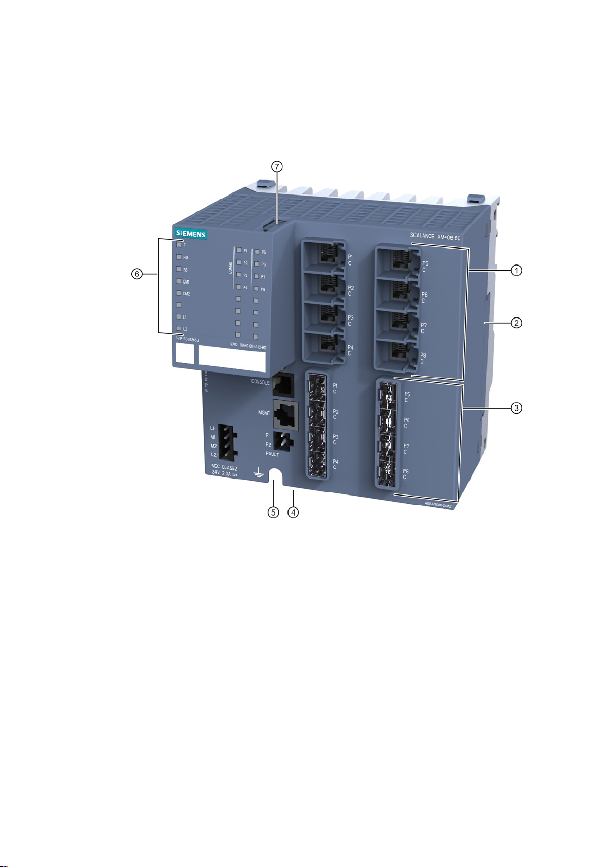
View of a SCALANCE XM408-8C device
①
Electrical ports
②
Expansion interface with cover
③
Slots for SFP transceivers
④
Location for securing to an S7 standard rail
⑤
Grounding
⑥
LED display
⑦
Slots for C-PLUG / KEY-PLUG
2.5 Views
The following figure shows an overview of the components of the SCALANCE XM408-8C.
SCALANCE XM-400
18 Operating Instructions, 05/2014, C79000-G8976-C306-03
Description of the device
2.5.3
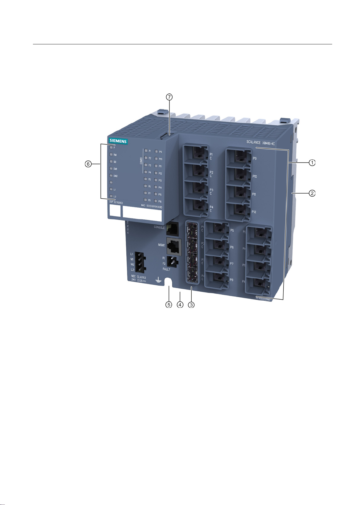
View of a SCALANCE XM416-4C device
①
Electrical ports
②
Expansion interface with cover
③
Slots for SFP transceivers
④
Location for securing to an S7 standard rail
⑤
Grounding
⑥
LED display
⑦
Slots for C-PLUG / KEY-PLUG
2.5 Views
The following figure shows an overview of the components of the SCALANCE XM416-4C.
SCALANCE XM-400
Operating Instructions, 05/2014, C79000-G8976-C306-03
19
Description of the device
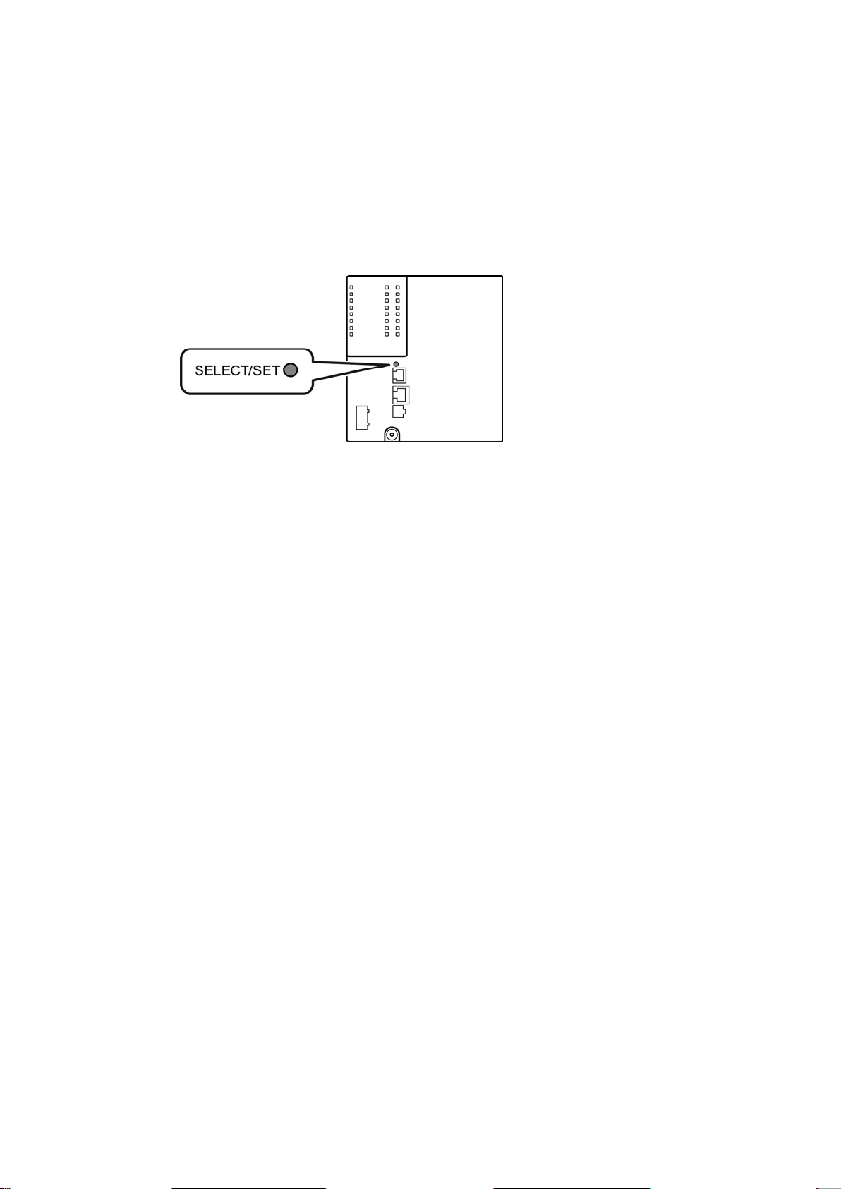
2.6
SELECT / SET button
Position
Setting the display mode
Resetting the device to factory defaults
2.6 SELECT / SET button
The "SELECT/SET" button is located on the front of the SCALANCE XM-400.
Figure 2-1 Position of the "SELECT/SET" button on the SCALANCE XM-400
To set the required display mode, press the "SELECT/SET" button.
For more detailed information on the display modes, refer to the section "LEDs "DM1" and
"DM2" (Page 25)".
If you reset, all the changes you have made will be overwritten by factory defaults.
To reset the device to the factory defaults, follow the steps below:
1. Switch to display mode A.
Display mode A is active if the LEDS "DM1" and "DM2" are unlit.
If the "DM1" and "DM2" LEDs are lit or flashing, you will need to press the "SET/SELECT"
repeatedly until the "DM1" and "DM2" LEDs go off.
If you do not press the "SELECT/SET" button for longer than 1 minute, the device
automatically changes to display mode A.
2. Hold down the "SELECT/SET" button for 12 seconds.
After 9 seconds,the "DM1" and "DM2" LEDs start to flash for 3 seconds. At the same
time, the port LEDs go on one after the other.
After you have held down the button for 12 seconds, the factory defaults are restored.
If you release the button before the 12 seconds have elapsed, the reset is canceled.
SCALANCE XM-400
20 Operating Instructions, 05/2014, C79000-G8976-C306-03

Description of the device
CAUTION
Restart with the SELECT/SET button disabled for "Restore Factory Defaults"
Defining the fault mask
2.6 SELECT / SET button
If you have disabled the SELECT/SET button for "Restore Factory Defaults" in the
configuration, this does not apply during the startup phase. When you restart after cycling
power, the configuration can nevertheless be deleted using this button. This action cannot
be undone and you then need to reload the device configuration. This can lead to
disturbances and failures in the corresponding network area.
Using the fault mask, you specify an individual "good status" for the connected ports and the
power supply. Deviations from this status are displayed as errors/faults.
To define the fault mask, follow the steps below:
1. Switch to display mode D.
Display mode D is active if the "DM1" and "DM2" LEDs are lit green..
If another display mode is active, you will need to press the "SET/SELECT" button
repeatedly until the "DM1" and "DM2" LEDs are lit green.
2. Hold down the "SELECT/SET" button for 5 seconds.
After 2 seconds,the "DM1" and "DM2" LEDs start to flash for 3 seconds. At the same
time, the port LEDs go on one after the other.
After you have held down the button for 5 seconds, the current settings are stored as the
"good status".
If you release the button before the 5 seconds have elapsed, the previous fault mask will
be retained.
SCALANCE XM-400
Operating Instructions, 05/2014, C79000-G8976-C306-03
21

Description of the device
Enabling/disabling the redundancy manager
Initial situation:
Result:
Initial situation:
Result:
2.6 SELECT / SET button
To enable/disable the redundancy manager, follow the steps below:
1. Switch to display mode B.
Display mode B is active if the "DM1" LED is lit green and the "DM2" LED is off..
If another display mode is active, you will need to press the "SET/SELECT" button
repeatedly until the "DM1" LED is lit green and the "DM2" LED is off.
2. Hold down the "SELECT/SET" button for 5 seconds.
After 2 seconds,the "DM1", "DM2" and "RM" LEDs start to flash for 3 seconds. At the
same time, the port LEDs go on one after the other.
If you release the button before the 5 seconds have elapsed, the action is canceled.
The result of the action depends on the initial situation:
–
The redundancy manager and media redundancy are disabled.
After enabling the redundancy manager, media redundancy is also enabled.
–
The redundancy manager and media redundancy are enabled.
After disabling the redundancy manager, media redundancy remains enabled.
SCALANCE XM-400
22 Operating Instructions, 05/2014, C79000-G8976-C306-03
Description of the device
2.7
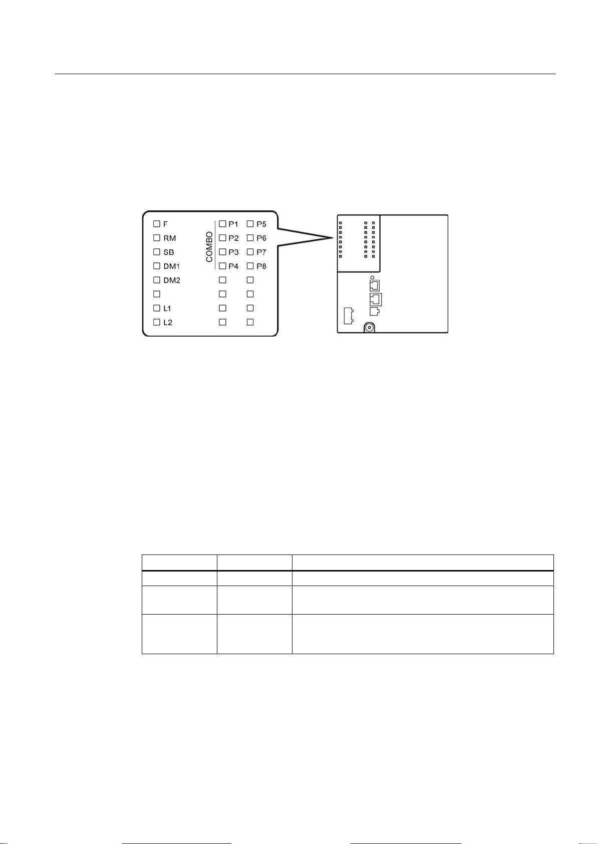
LED display
2.7.1
Overview
F
LED for displaying the fault/error status
RM
LED for displaying the "redundancy manager" function
SB
LED for displaying the "standby" function
DM1/DM2
LEDs for displaying the display mode
L1/L2
LEDs for displaying the power supply
P
LEDs for displaying the port status *)
COMBO
Indicates that the LEDs belong to combo ports
2.7.2
"RM" LED
LED color
LED status
Meaning
-
Off
The device is not a redundancy manager.
The ring is working without problems, monitoring is activated.
has switched through.
2.7 LED display
The following figure shows the arrangement of the LEDs.
*) The number of port LEDs depends on the device.
The "RM" LED indicates whether or not the device is a redundancy manager and whether or
not the ring is operating free of error.
Green On The device is a redundancy manager.
Green Flashing The device is a redundancy manager.
An interruption has been detected on the ring and the device
SCALANCE XM-400
Operating Instructions, 05/2014, C79000-G8976-C306-03
23
Description of the device
2.7.3
"SB" LED
LED color
LED status
Meaning
-
Off
The standby function is disabled.
passive.
Green
Flashing
The standby function is enabled. The standby section is active.
2.7.4
"F" LED
Meaning during device startup
LED color
LED status
Meaning during device startup
-
Off
Device startup was completed successfully.
Red
On
Device startup is not yet completed or errors have occurred.
Red
Flashing
There are errors in the firmware.
Meaning during operation
LED color
LED status
Meaning during operation
-
Off
The device is operating free of errors.
opened.
2.7 LED display
The "SB" LED shows the status of the standby function.
Green On The standby function is enabled. The standby section is
The "F" LED shows the fault/error status of the device.
Red On The device has detected a problem. The signaling contact has
SCALANCE XM-400
24 Operating Instructions, 05/2014, C79000-G8976-C306-03
 Loading...