


SIMATIC NET
Industrial Ethernet switches
SCALANCE XM-400/XR-500 Web
Based Management (WBM)
Introduction
1
Configuration Manual
Description
IP addresses
Technical basics
Configuring with Web Based
Management
Troubleshooting/FAQ
Appendix A
2
3
4
5
6
A
05/2017
C79000-G8976-C248-12

Legal information
Warning notice system
This manual contains notices you have to observe in order to ensure your personal safety, as well as to prevent
damage to property. The notices referring to your personal safety are highlighted in the manual by a safety alert
symbol, notices referring only to property damage have no safety alert symbol. These notices shown below are
graded according to the degree of danger.
DANGER
indicates that death or severe personal injury will result if proper precautions are not taken.
WARNING
indicates that death or severe personal injury may result if proper precautions are not taken.
CAUTION
indicates that minor personal injury can result if proper precautions are not taken.
NOTICE
indicates that property damage can result if proper precautions are not taken.
If more than one degree of danger is present, the warning notice representing the highest degree of danger will be
used. A notice warning of injury to persons with a safety alert symbol may also include a warning relating to property
damage.
Qualified Personnel
The product/system described in this documentation may be operated only by personnel qualified for the specific
task in accordance with the relevant documentation, in particular its warning notices and safety instructions. Qualified
personnel are those who, based on their training and experience, are capable of identifying risks and avoiding
potential hazards when working with these products/systems.
Proper use of Siemens products
Note the following:
WARNING
Siemens products may only be used for the applications described in the catalog and in the relevant technical
documentation. If products and components from other manufacturers are used, these must be recommended or
approved by Siemens. Proper transport, storage, installation, assembly, commissioning, operation and
maintenance are required to ensure that the products operate safely and without any problems. The permissible
ambient conditions must be complied with. The information in the relevant documentation must be observed.
Trademarks
All names identified by ® are registered trademarks of Siemens AG. The remaining trademarks in this publication
may be trademarks whose use by third parties for their own purposes could violate the rights of the owner.
Disclaimer of Liability
We have reviewed the contents of this publication to ensure consistency with the hardware and software described.
Since variance cannot be precluded entirely, we cannot guarantee full consistency. However, the information in
this publication is reviewed regularly and any necessary corrections are included in subsequent editions.
Siemens AG
Division Process Industries and Drives
Postfach 48 48
90026 NÜRNBERG
GERMANY
C79000-G8976-C248-12
Ⓟ 05/2017 Subject to change
Copyright © Siemens AG 2011 - 2017.
All rights reserved

Table of contents
1 Introduction.................................................................................................................................................11
1.1 Information on this configuration manual...............................................................................11
2 Description..................................................................................................................................................15
2.1 Product characteristics...........................................................................................................15
2.2 Requirements for installation and operation...........................................................................17
2.3 C-PLUG / KEY-PLUG............................................................................................................17
2.4 Power over Ethernet (PoE)....................................................................................................18
3 IP addresses...............................................................................................................................................21
3.1 IPv4 / IPv6..............................................................................................................................21
3.2 IPv4 address..........................................................................................................................23
3.2.1 Structure of an IPv4 address..................................................................................................23
3.2.2 Initial assignment of an IPv4 address....................................................................................24
3.2.3 Address assignment with DHCP............................................................................................25
3.3 IPv6 addresses......................................................................................................................26
3.3.1 IPv6 terms..............................................................................................................................26
3.3.2 Structure of an IPv6 address..................................................................................................28
4 Technical basics.........................................................................................................................................31
4.1 Configuration limits.................................................................................................................31
4.2 SNMP.....................................................................................................................................35
4.3 RCDP.....................................................................................................................................37
4.4 VLAN......................................................................................................................................37
4.4.1 Basics.....................................................................................................................................37
4.4.2 VLAN tagging.........................................................................................................................38
4.4.3 Private VLAN..........................................................................................................................40
4.4.4 VLAN tunnel...........................................................................................................................42
4.5 Mirroring.................................................................................................................................43
4.6 Redundancy mechanism........................................................................................................44
4.6.1 Spanning Tree........................................................................................................................44
4.6.1.1 RSTP, MSTP, CIST...............................................................................................................45
4.6.2 HRP........................................................................................................................................46
4.6.3 MRP.......................................................................................................................................47
4.6.3.1 MRP - Media Redundancy Protocol ......................................................................................47
4.6.3.2 Configuration in WBM............................................................................................................50
4.6.3.3 Configuration in STEP 7.........................................................................................................50
4.6.4 Standby..................................................................................................................................55
4.6.5 Link Check.............................................................................................................................56
4.7 Link aggregation.....................................................................................................................57
SCALANCE XM-400/XR-500 Web Based Management (WBM)
Configuration Manual, 05/2017, C79000-G8976-C248-12 3

Table of contents
4.8 Routing function.....................................................................................................................58
4.8.1 Static routing..........................................................................................................................58
4.8.2 VRRP.....................................................................................................................................59
4.8.2.1 VRRPv2.................................................................................................................................59
4.8.2.2 VRRP3...................................................................................................................................59
4.8.3 OSPF.....................................................................................................................................60
4.8.3.1 OSPFv2..................................................................................................................................60
4.8.3.2 OSPFv3..................................................................................................................................64
4.8.4 RIP.........................................................................................................................................65
4.8.4.1 RIPv2.....................................................................................................................................65
4.8.4.2 RIPng.....................................................................................................................................66
4.8.5 PIM.........................................................................................................................................66
4.9 NAT/NAPT.............................................................................................................................68
5 Configuring with Web Based Management................................................................................................73
5.1 Web Based Management.......................................................................................................73
5.2 Login......................................................................................................................................74
5.3 The "Information" menu.........................................................................................................78
5.3.1 Start page...............................................................................................................................78
5.3.2 Versions.................................................................................................................................83
5.3.3 Identification & Maintenance..................................................................................................84
5.3.4 ARP / Neighbors....................................................................................................................86
5.3.4.1 ARP Table..............................................................................................................................86
5.3.4.2 IPv6 Neighbor Table..............................................................................................................87
5.3.5 Log Table...............................................................................................................................87
5.3.6 Faults.....................................................................................................................................89
5.3.7 Redundancy...........................................................................................................................91
5.3.7.1 Spanning Tree........................................................................................................................91
5.3.7.2 VRRP statistics......................................................................................................................94
5.3.7.3 VRRP Statistics......................................................................................................................96
5.3.7.4 Ring redundancy....................................................................................................................98
5.3.7.5 Standby................................................................................................................................100
5.3.7.6 Link Check...........................................................................................................................101
5.3.8 Ethernet Statistics................................................................................................................103
5.3.8.1 Interface Statistics................................................................................................................103
5.3.8.2 Packet Size..........................................................................................................................104
5.3.8.3 Packet Type.........................................................................................................................105
5.3.8.4 Packet Error.........................................................................................................................106
5.3.8.5 History..................................................................................................................................108
5.3.9 Unicast.................................................................................................................................109
5.3.10 Multicast...............................................................................................................................110
5.3.10.1 Multicast...............................................................................................................................110
5.3.10.2 IGMP Groups.......................................................................................................................112
5.3.11 LLDP....................................................................................................................................113
5.3.12 Fiber Monitoring Protocol.....................................................................................................114
5.3.13 IPv4 routing..........................................................................................................................116
5.3.13.1 Routing Table.......................................................................................................................116
5.3.13.2 OSPFv2 Interfaces...............................................................................................................117
5.3.13.3 OSPFv2 Neighbors..............................................................................................................118
5.3.13.4 OSPFv2 Virtual Neighbors...................................................................................................120
SCALANCE XM-400/XR-500 Web Based Management (WBM)
4 Configuration Manual, 05/2017, C79000-G8976-C248-12

Table of contents
5.3.13.5 OSPFv2 LSDB.....................................................................................................................122
5.3.13.6 RIPv2 Statistics....................................................................................................................123
5.3.13.7 NAT Translations.................................................................................................................124
5.3.13.8 PIM interfaces......................................................................................................................125
5.3.13.9 PIM Neighbors.....................................................................................................................126
5.3.13.10 PIM Routes..........................................................................................................................127
5.3.13.11 PIM RPs...............................................................................................................................128
5.3.13.12 PIM BSRs.............................................................................................................................129
5.3.13.13 MSDP Cache.......................................................................................................................130
5.3.14 IPv6 routing..........................................................................................................................131
5.3.14.1 IPv6 Routing Table..............................................................................................................131
5.3.14.2 OSPFv3 Interfaces...............................................................................................................132
5.3.14.3 OSPFv3 Neighbors..............................................................................................................133
5.3.14.4 OSPFv3 Virtual Neighbors...................................................................................................135
5.3.14.5 OSPFv3 AS-Scope LSDB....................................................................................................136
5.3.14.6 OSPFv3 Area-Scope LSDB.................................................................................................137
5.3.14.7 OSPFv3 Link-Scope LSDB..................................................................................................139
5.3.14.8 RIPng Statistics....................................................................................................................140
5.3.15 DHCP Server.......................................................................................................................141
5.3.16 SNMP...................................................................................................................................143
5.3.17 Security................................................................................................................................143
5.3.17.1 Overview..............................................................................................................................143
5.3.17.2 Supported Function Rights...................................................................................................146
5.3.17.3 Roles....................................................................................................................................147
5.3.17.4 Groups.................................................................................................................................148
5.4 The "System" menu.............................................................................................................148
5.4.1 Configuration........................................................................................................................148
5.4.2 General................................................................................................................................152
5.4.2.1 Device..................................................................................................................................152
5.4.2.2 Coordinates..........................................................................................................................153
5.4.3 Agent IP...............................................................................................................................154
5.4.4 DNS......................................................................................................................................154
5.4.5 Restart..................................................................................................................................156
5.4.6 Load & Save.........................................................................................................................158
5.4.6.1 HTTP....................................................................................................................................159
5.4.6.2 TFTP....................................................................................................................................162
5.4.6.3 Passwords............................................................................................................................166
5.4.7 Events..................................................................................................................................167
5.4.7.1 Configuration........................................................................................................................167
5.4.7.2 Severity Filters.....................................................................................................................170
5.4.8 SMTP client..........................................................................................................................171
5.4.9 DHCP...................................................................................................................................173
5.4.9.1 DHCP Client.........................................................................................................................173
5.4.9.2 DHCP Server.......................................................................................................................174
5.4.9.3 Port-IP Address Mapping.....................................................................................................178
5.4.9.4 Port Range...........................................................................................................................179
5.4.9.5 DHCP Options......................................................................................................................180
5.4.9.6 Relay Agent Information.......................................................................................................183
5.4.9.7 Static Leases........................................................................................................................184
5.4.10 SNMP...................................................................................................................................186
5.4.10.1 General................................................................................................................................186
5.4.10.2 Traps....................................................................................................................................189
SCALANCE XM-400/XR-500 Web Based Management (WBM)
Configuration Manual, 05/2017, C79000-G8976-C248-12 5

Table of contents
5.4.10.3 v3 Groups.............................................................................................................................190
5.4.10.4 v3 Users...............................................................................................................................192
5.4.11 System Time........................................................................................................................194
5.4.11.1 Manual Setting.....................................................................................................................195
5.4.11.2 DST Overview......................................................................................................................197
5.4.11.3 DST Configuration................................................................................................................199
5.4.11.4 SNTP Client.........................................................................................................................202
5.4.11.5 NTP Client............................................................................................................................205
5.4.11.6 SIMATIC time client.............................................................................................................207
5.4.11.7 PTP Client............................................................................................................................208
5.4.12 Automatic logout..................................................................................................................210
5.4.13 Configuration of the SELECT/SET button............................................................................210
5.4.14 Syslog Client........................................................................................................................212
5.4.15 Ports.....................................................................................................................................214
5.4.15.1 Overview..............................................................................................................................214
5.4.15.2 Configuration........................................................................................................................217
5.4.16 Fault Monitoring...................................................................................................................222
5.4.16.1 Power Supply.......................................................................................................................222
5.4.16.2 Link Change.........................................................................................................................223
5.4.16.3 Redundancy.........................................................................................................................225
5.4.17 PROFINET...........................................................................................................................225
5.4.18 EtherNet/IP...........................................................................................................................227
5.4.19 PLUG...................................................................................................................................228
5.4.19.1 Configuration........................................................................................................................228
5.4.19.2 License.................................................................................................................................232
5.4.20 Ping......................................................................................................................................234
5.4.21 PoE......................................................................................................................................235
5.4.21.1 General................................................................................................................................235
5.4.21.2 Port.......................................................................................................................................238
5.4.22 Port Diagnostics...................................................................................................................240
5.4.22.1 Cable Tester.........................................................................................................................240
5.4.22.2 SFP diagnostics...................................................................................................................242
5.4.23 Configuration Backup...........................................................................................................243
5.5 The "Layer 2" menu.............................................................................................................245
5.5.1 Configuration........................................................................................................................245
5.5.2 QoS......................................................................................................................................249
5.5.2.1 CoS queue mapping............................................................................................................249
5.5.2.2 DSCP Mapping....................................................................................................................251
5.5.2.3 QoS Trust.............................................................................................................................252
5.5.3 Rate Control.........................................................................................................................254
5.5.4 VLAN....................................................................................................................................256
5.5.4.1 General................................................................................................................................256
5.5.4.2 GVRP...................................................................................................................................259
5.5.4.3 Port-based VLAN.................................................................................................................261
5.5.4.4 Protocol-based VLAN group................................................................................................263
5.5.4.5 Protocol-based VLAN port...................................................................................................264
5.5.4.6 IPv4 subnet-based VLAN.....................................................................................................266
5.5.4.7 IPv6 prefix-based VLAN.......................................................................................................267
5.5.5 Private VLAN........................................................................................................................269
5.5.5.1 General................................................................................................................................269
5.5.5.2 IP Interface Mapping............................................................................................................270
5.5.6 Provider bridge.....................................................................................................................272
SCALANCE XM-400/XR-500 Web Based Management (WBM)
6 Configuration Manual, 05/2017, C79000-G8976-C248-12

Table of contents
5.5.6.1 Tunnel ports.........................................................................................................................272
5.5.7 Mirroring...............................................................................................................................274
5.5.7.1 General................................................................................................................................274
5.5.7.2 Port.......................................................................................................................................279
5.5.7.3 VLAN....................................................................................................................................280
5.5.7.4 MAC Flow.............................................................................................................................281
5.5.7.5 IP Flow.................................................................................................................................282
5.5.8 Dynamic MAC Aging............................................................................................................283
5.5.9 Ring redundancy..................................................................................................................284
5.5.9.1 Ring......................................................................................................................................284
5.5.9.2 Standby................................................................................................................................287
5.5.9.3 Link Check...........................................................................................................................290
5.5.10 Spanning tree.......................................................................................................................292
5.5.10.1 General................................................................................................................................292
5.5.10.2 CIST General.......................................................................................................................293
5.5.10.3 CIST Port.............................................................................................................................295
5.5.10.4 MST General........................................................................................................................300
5.5.10.5 MST Port..............................................................................................................................301
5.5.10.6 Enhanced Passive Listening Compatibility..........................................................................303
5.5.11 Loop Detection.....................................................................................................................304
5.5.12 Link aggregation...................................................................................................................307
5.5.13 DCP forwarding....................................................................................................................310
5.5.14 LLDP....................................................................................................................................312
5.5.15 Fiber Monitoring Protocol.....................................................................................................313
5.5.16 Unicast.................................................................................................................................315
5.5.16.1 Filtering................................................................................................................................315
5.5.16.2 Locked Ports........................................................................................................................317
5.5.16.3 Learning...............................................................................................................................319
5.5.16.4 Blocking................................................................................................................................320
5.5.17 Multicast...............................................................................................................................321
5.5.17.1 Groups.................................................................................................................................321
5.5.17.2 IGMP snooping....................................................................................................................324
5.5.17.3 GMRP..................................................................................................................................325
5.5.17.4 Multicast blocking.................................................................................................................327
5.5.17.5 MLD (IPv6)...........................................................................................................................328
5.5.18 Broadcast.............................................................................................................................330
5.5.19 PTP......................................................................................................................................332
5.5.19.1 General................................................................................................................................332
5.5.19.2 TC General...........................................................................................................................333
5.5.19.3 TC Port.................................................................................................................................334
5.5.20 RMON..................................................................................................................................335
5.5.20.1 Statistics...............................................................................................................................335
5.5.20.2 History..................................................................................................................................337
5.6 The "Layer 3 (IPv4)" menu...................................................................................................339
5.6.1 Configuration........................................................................................................................339
5.6.2 Subnets................................................................................................................................340
5.6.2.1 Overview..............................................................................................................................340
5.6.2.2 Configuration........................................................................................................................343
5.6.3 NAT......................................................................................................................................345
5.6.3.1 NAT......................................................................................................................................345
5.6.3.2 Static....................................................................................................................................347
5.6.3.3 Pool......................................................................................................................................348
SCALANCE XM-400/XR-500 Web Based Management (WBM)
Configuration Manual, 05/2017, C79000-G8976-C248-12 7

Table of contents
5.6.3.4 NAPT....................................................................................................................................349
5.6.4 Static Routes........................................................................................................................351
5.6.5 Route Maps..........................................................................................................................353
5.6.5.1 General................................................................................................................................353
5.6.5.2 Interface & Value Match.......................................................................................................354
5.6.5.3 Destination Match................................................................................................................356
5.6.5.4 Next Hop Match..................................................................................................................357
5.6.5.5 Create..................................................................................................................................358
5.6.6 DHCP Relay Agent..............................................................................................................359
5.6.6.1 General................................................................................................................................359
5.6.6.2 Option...................................................................................................................................361
5.6.7 VRRP...................................................................................................................................364
5.6.7.1 Router..................................................................................................................................364
5.6.7.2 Configuration........................................................................................................................367
5.6.7.3 Address overview.................................................................................................................369
5.6.7.4 Address Configuration..........................................................................................................369
5.6.7.5 Interface Tracking................................................................................................................370
5.6.8 VRRPv3...............................................................................................................................372
5.6.8.1 Router..................................................................................................................................372
5.6.8.2 Configuration........................................................................................................................375
5.6.8.3 Addresses Overview............................................................................................................377
5.6.8.4 Addresses Configuration......................................................................................................377
5.6.8.5 Interface Tracking................................................................................................................378
5.6.9 OSPFv2................................................................................................................................380
5.6.9.1 Configuration........................................................................................................................380
5.6.9.2 Areas....................................................................................................................................382
5.6.9.3 Area Range..........................................................................................................................383
5.6.9.4 Interfaces.............................................................................................................................385
5.6.9.5 Interface Authentication.......................................................................................................387
5.6.9.6 Virtual Links..........................................................................................................................388
5.6.9.7 Virtual Link Authentication....................................................................................................391
5.6.10 RIPv2...................................................................................................................................392
5.6.10.1 Configuration........................................................................................................................392
5.6.10.2 Interfaces.............................................................................................................................393
5.6.11 IGMP....................................................................................................................................395
5.6.12 PIM.......................................................................................................................................397
5.6.12.1 PIM.......................................................................................................................................397
5.6.12.2 Interface...............................................................................................................................397
5.6.12.3 RP Static..............................................................................................................................398
5.6.12.4 RP Candidate.......................................................................................................................400
5.6.13 MSDP...................................................................................................................................401
5.6.13.1 MSDP...................................................................................................................................401
5.6.13.2 Peer......................................................................................................................................403
5.7 The "Layer 3 (IPv6)" menu...................................................................................................404
5.7.1 Configuration........................................................................................................................404
5.7.2 Subnets................................................................................................................................406
5.7.3 DHCPv6 client......................................................................................................................408
5.7.3.1 DHCPv6 client......................................................................................................................408
5.7.3.2 DHCPv6 PD Sub Client........................................................................................................409
5.7.4 Static Routes........................................................................................................................411
5.7.5 Route maps..........................................................................................................................412
5.7.5.1 General................................................................................................................................412
SCALANCE XM-400/XR-500 Web Based Management (WBM)
8 Configuration Manual, 05/2017, C79000-G8976-C248-12

Table of contents
5.7.5.2 Interface & Value Match.......................................................................................................413
5.7.5.3 Destination Match...............................................................................................................416
5.7.5.4 Next-Hop filtern....................................................................................................................416
5.7.5.5 Einstellen..............................................................................................................................417
5.7.6 DHCPv4 Relay Agent...........................................................................................................419
5.7.6.1 Interfaces.............................................................................................................................419
5.7.6.2 Server Addresses.................................................................................................................420
5.7.6.3 Outgoing Interfaces..............................................................................................................421
5.7.7 VRRPv3...............................................................................................................................422
5.7.7.1 Routers.................................................................................................................................422
5.7.7.2 Configuration........................................................................................................................425
5.7.7.3 Addresses Overview............................................................................................................427
5.7.7.4 Addresses Configuration......................................................................................................428
5.7.7.5 Interface Tracking................................................................................................................429
5.7.8 OSPFv3................................................................................................................................430
5.7.8.1 Configuration........................................................................................................................430
5.7.8.2 Areas....................................................................................................................................432
5.7.8.3 Area......................................................................................................................................434
5.7.8.4 Interfaces.............................................................................................................................435
5.7.8.5 Virtual Links..........................................................................................................................437
5.7.9 RIPng...................................................................................................................................439
5.7.9.1 RIPng Configuration.............................................................................................................439
5.7.9.2 RIPng interfaces...................................................................................................................440
5.8 The "Security" menu............................................................................................................441
5.8.1 User management................................................................................................................441
5.8.2 Users....................................................................................................................................444
5.8.2.1 Local Users..........................................................................................................................444
5.8.2.2 Roles....................................................................................................................................447
5.8.2.3 Groups.................................................................................................................................449
5.8.3 Passwords............................................................................................................................451
5.8.3.1 Passwords............................................................................................................................451
5.8.3.2 Options.................................................................................................................................453
5.8.4 AAA......................................................................................................................................453
5.8.4.1 General................................................................................................................................453
5.8.4.2 RADIUS Client.....................................................................................................................454
5.8.4.3 802.1x Authenticator............................................................................................................458
5.8.5 MAC ACL.............................................................................................................................463
5.8.5.1 Rules Configuration..............................................................................................................463
5.8.5.2 Ingress Rules.......................................................................................................................465
5.8.5.3 Egress Rules........................................................................................................................467
5.8.6 IP ACL..................................................................................................................................469
5.8.6.1 Rules Configuration..............................................................................................................469
5.8.6.2 Protocol Configuration..........................................................................................................470
5.8.6.3 Ingress Rules.......................................................................................................................472
5.8.6.4 Egress Rules........................................................................................................................475
5.8.7 Management ACL................................................................................................................477
6 Troubleshooting/FAQ...............................................................................................................................481
6.1 Firmware update - via WBM.................................................................................................481
6.2 Firmware update via WBM or CLI not possible....................................................................481
6.3 Message: SINEMA configuration not yet accepted..............................................................482
SCALANCE XM-400/XR-500 Web Based Management (WBM)
Configuration Manual, 05/2017, C79000-G8976-C248-12 9

Table of contents
A Appendix A...............................................................................................................................................485
A.1 Supported RFCs..................................................................................................................485
Index.........................................................................................................................................................487
SCALANCE XM-400/XR-500 Web Based Management (WBM)
10 Configuration Manual, 05/2017, C79000-G8976-C248-12

Introduction
1.1 Information on this configuration manual
Validity of the configuration manual
This Configuration Manual covers the following products:
● SCALANCE XR-500
– SCALANCE XR524-8C
– SCALANCE XR526-8C
– SCALANCE XR528-6M
– SCALANCE XR552-12M
The devices are available with or without routing functions. The routing function can either
be integrated in the devices or made available with a KEY-PLUG.
● SCALANCE XM-400
– SCALANCE XM408-4C
– SCALANCE XM408-8C
1
– SCALANCE XM416-4C
The devices are available with or without routing functions. The routing function can either
be integrated in the devices or made available with a KEY-PLUG.
This Configuration Manual applies to the following software version:
● SCALANCE XR-500 firmware as of version 6.1
● SCALANCE XM-400 firmware as of version 6.1
Purpose of the Configuration Manual
This Configuration Manual is intended to provide you with the information you require to install,
commission and operate IE switches. It provides you with the information you require to
configure the IE switches.
SCALANCE XM-400/XR-500 Web Based Management (WBM)
Configuration Manual, 05/2017, C79000-G8976-C248-12 11

Introduction
1.1 Information on this configuration manual
Orientation in the documentation
Apart from this configuration manual, the products also have the following documentation:
● Configuration Manual:
– SCALANCE XM-400/XR-500 Command Line Interface (CLI)
This document contains the CLI commands that are supported by the IE switches
SCALANCE XM-400 and SCALANCE XR-500.
● Operating instructions:
– SCALANCE XR-500
– MM900 media modules for SCALANCE XR-500M
– Fan unit FAN597-1 for SCALANCE XR-500M
– Power supply PS598-1 for SCALANCE XR-500M
– SCALANCE XM-400
– Extender for SCALANCE XM-400
– Pluggable transceiver SFP/SFP+/SCP/STP
Terms used
– PoE power supply SCALANCE PS9230 PoE / SCALANCE PS924 PoE
These documents contain information on installing and connecting up and approvals for
the products.
The following documentation is also available from SIMATIC NET on the topic of Industrial
Ethernet:
● System manual "Industrial Ethernet / PROFINET"
● System manual "Industrial Ethernet / PROFINET - Passive network components"
All these documents are available on the SCALANCE X DVD.
The designation . . . stands for . . .
IE switch Industrial Ethernet switch
IPv4 address IPv4 address
IPv6 address IPv6 address
IP address IPv4/IPv6 address
IPv4 interface Interface that supports IPv4.
IPv6 interface Interface that supports IPv6. The interface can have more than one IPv6
address The IPv6 addresses have different ranges (scope), e.g. link local
IP interface Interface that supports both IPv4 and IPv6. As default the IPv4 support
is already activated. The IPv6 support needs to be activated extra.
SCALANCE XM-400/XR-500 Web Based Management (WBM)
12 Configuration Manual, 05/2017, C79000-G8976-C248-12

What's new as of version 6.1?
Below, you will find an overview of the most important function expansions:
● Information in the configuration limits
● RCDP
● DHCP
– Assignment of port to IP address
● Firmware on PLUG
● Configuration Backup
● IPv6 prefix-based VLAN
● Q-in-Q VLAN tunnel
● Link Check
● Loopback functionality
● PIM
– "Bidirectional multicast" functionality
Introduction
1.1 Information on this configuration manual
● MSDP
Note
Default user "user" set in the factory
As of firmware version 6.0 the default user set in the factory "user" is no longer available when
the product ships.
If you update a device to the firmware V6.0 the default user set in the factory "user" is initially
still available. If you reset the device to the factory settings ("Restore Factory Defaults and
Restart") the default user set in the factory "user" is deleted.
You can create new users with the role "user".
SIMATIC NET glossary
Explanations of many of the specialist terms used in this documentation can be found in the
SIMATIC NET glossary.
You will find the SIMATIC NET glossary here:
● SIMATIC NET Manual Collection or product DVD
The DVD ships with certain SIMATIC NET products.
● On the Internet under the following address:
50305045 (http://support.automation.siemens.com/WW/view/en/50305045)
SCALANCE XM-400/XR-500 Web Based Management (WBM)
Configuration Manual, 05/2017, C79000-G8976-C248-12 13

Introduction
1.1 Information on this configuration manual
Security information
Siemens provides products and solutions with industrial security functions that support the
secure operation of plants, solutions, machines, equipment and/or networks. They are
important components in a holistic industrial security concept. With this in mind, Siemens’
products and solutions undergo continuous development. Siemens recommends strongly that
you regularly check for product updates.
For the secure operation of Siemens products and solutions, it is necessary to take suitable
preventive action (e.g. cell protection concept) and integrate each component into a holistic,
state-of-the-art industrial security concept. Third-party products that may be in use should also
be considered. For more information about industrial security, visit http://www.siemens.com/
industrialsecurity.
To stay informed about product updates as they occur, sign up for a product-specific
newsletter. For more information, visit http://support.automation.siemens.com.
License conditions
Note
Open source software
Trademarks
Firmware
Read the license conditions for open source software carefully before using the product.
You will find license conditions in the following documents on the supplied data medium:
● DOC_OSS-SCALANCE-X_74.pdf
● DC_LicenseSummaryScalanceXM400_76.pdf
● DC_LicenseSummaryScalanceXR500_76.pdf
You will find these documents on the product DVD in the following directory: /Open Source
Information
The following and possibly other names not identified by the registered trademark sign ® are
registered trademarks of Siemens AG:
SIMATIC NET, SCALANCE, C-PLUG, OLM
The firmware is signed and encrypted. This ensures that only firmware created by Siemens
can be downloaded to the device.
SCALANCE XM-400/XR-500 Web Based Management (WBM)
14 Configuration Manual, 05/2017, C79000-G8976-C248-12

Description
2.1 Product characteristics
Properties of the IE switches
● The Ethernet interfaces support the following modes:
– 10 Mbps and 100 Mbps both in full and half duplex
– 1000 Mbps full duplex
– Autocrossing
– Autopolarity
● Redundancy protocols Multiple Spanning Tree Protocol (MSTP), Rapid Spanning Tree
Protocol (RSTP) and Spanning Tree Protocol (STP)
This means part of a network can be connected redundantly to a higher-level company
network. The reconfiguration time of the network is in the seconds range and therefore
takes longer than the ring redundancy method.
● Virtual networks (VLAN)
To structure Industrial Ethernet networks with a fast growing number of nodes, a physical
network can be divided into several virtual subnets. Port-based, protocol-based and subnetbased VLANs are available.
2
Layer 3 functions
● Load limitation when using multicast protocols, for example video transmission
By learning the multicast sources and destinations (IGMP snooping, IGMP querier), the IE
switches can filter multicast data traffic and limit the load in the network. Multicast and
broadcast data traffic can be limited.
● Time-of-day synchronization
Diagnostics messages (log table entries, e-mails) are given a time stamp. The local time
is uniform throughout the network thanks to synchronization with a SICLOCK time
transmitter or SNTP/NTP/PTP server and therefore makes the identification of diagnostics
messages of several devices easier.
● Link aggregation (IEEE 802.1AX) for bundling ports
● Quality of Service for classification of the network traffic is according to COS (Class of
Service - IEEE 802.11Q) and DSCP (Differentiated Services Code Point - RFC 2474)
The following functions are only available on devices with routing functions:
● Static routing
● OSPF / OSPFv3
● VRRP / VRRPv3
● RIP / RIPng
SCALANCE XM-400/XR-500 Web Based Management (WBM)
Configuration Manual, 05/2017, C79000-G8976-C248-12 15

Description
2.1 Product characteristics
● IGMP
● PIM
● MSDP
There are devices that natively support all routing functions. You will find the order numbers
in the operating instructions of the devices.
On the devices that only support layer 2, you can enable the routing functions with a KEYPLUG.
Naming interfaces
Interface names with SCALANCE XM-400
● Interfaces of the basic device
The interfaces of the basic device SCALANCE XM-400 are called module 1.
● Interfaces of extenders
The port extenders are called module 2 and module 3 starting from the basic device. The
number of port extenders depends on the number of ports of the basic device.
The extender function is called module 0.
Combo ports
Interface names with SCALANCE XR-500
● Permanently integrated Interfaces
The interfaces permanently installed in the SCALANCE XR-500 are identified with module
0.
● Interfaces of modules
The slots for modules are called module 1 followed by numbers. The numbering range
depends on the hardware configuration. The numbering is fixed and does not depend on
the number of modules being used.
Each module has 4 ports numbered 1 to 4.
Combo port is the name for two communication ports. A combo port has the two following plugin options:
● a fixed RJ-45 port
● an SFP transceiver slot that can be equipped individually
Of these two ports, only one can ever be active.
You can set the active port on the WBM page "System > Ports > Configuration"with the CLI
command media-type.
SCALANCE XM-400/XR-500 Web Based Management (WBM)
16 Configuration Manual, 05/2017, C79000-G8976-C248-12

2.2 Requirements for installation and operation
Requirements for installation and operation of the IE switches
A PG/PC with a network connection must be available in order to configure the IE switches. If
no DHCP server is available, a PG/PC on which the Primary Setup Tool (PST) is installed is
necessary for the initial assignment of an IP address to the IE switches. For the other
configuration settings, a PG/PC with Telnet or an Internet browser is necessary.
Serial interface
The IE switches have a serial interface. An IP address is unnecessary to be able to access
the device via the serial interface. A serial cable ships with the products.
Set the following parameters for the connection:
● Bits per second: 115200
● Data bits: 8
● Parity: None
● Stop bits: 1
Description
2.3 C-PLUG / KEY-PLUG
● Flow control: None
2.3 C-PLUG / KEY-PLUG
Configuration information on the C-PLUG / KEY-PLUG
The C-PLUG / KEY-PLUG is used to transfer the configuration of the old device to the new
device when a device is replaced.
NOTICE
Do not remove or insert a C-PLUG / KEY-PLUG during operation!
A C-PLUG / KEY-PLUG may only be removed or inserted when the device is turned off.
The device regularly checks whether or not a KEY-PLUG is present. If it is detected that the
KEY-PLUG was removed, there is a restart. If a valid KEY-PLUG was inserted in the device,
the device changes to a defined error state following the restart.
When the new device starts up with the C-PLUG / KEY-PLUG, it then continues automatically
with exactly the same configuration as the old device. One exception to this can be the IP
configuration if it is set over DHCP and the DHCP server has not been reconfigured accordingly.
SCALANCE XM-400/XR-500 Web Based Management (WBM)
Configuration Manual, 05/2017, C79000-G8976-C248-12 17

Description
2.4 Power over Ethernet (PoE)
A reconfiguration is necessary if you use functions based on MAC addresses.
Note
In terms of the C-PLUG / KEY-PLUG, the SCALANCE devices work in two modes:
● Without C-PLUG / KEY-PLUG
The device stores the configuration in internal memory. This mode is active when no CPLUG / KEY-PLUG is inserted.
● With C-PLUG / KEY-PLUG
The configuration stored on the C-PLUG / KEY-PLUG is displayed over the user interfaces.
If changes are made to the configuration, the device stores the configuration directly on the
C-PLUG / KEY-PLUG and in the internal memory. This mode is active as soon as a CPLUG / KEY-PLUG is inserted. When the device is started with a C-PLUG / KEY-PLUG
inserted, the device starts up with the configuration data on the C-PLUG / KEY-PLUG.
Note
Incompatibility with previous versions with C-PLUG / KEY-PLUG inserted
During the installation of a previous version of the firmware, the configuration data can be lost.
In this case, the device starts up with the factory settings after the firmware has been installed.
In this situation, if a C-PLUG / KEY-PLUG is inserted in the device, following the restart, this
has the status "Not Accepted" since the C-PLUG / KEY-PLUG still has the configuration data
of the previous more up-to-date firmware. This allows you to return to the previous, more upto-date firmware without any loss of configuration data. If the original configuration on the CPLUG / KEY-PLUG is no longer required, the C-PLUG / KEY-PLUG can be deleted or rewritten
manually.
License information on the KEY-PLUG
In addition to the configuration, the KEY-PLUG also contains a license that allows the use of
layer 3 functions.
2.4 Power over Ethernet (PoE)
General
"Power over Ethernet" (PoE) is a power supply technique for network components according
to IEEE 802.3af or IEEE 802.3at. The power is supplied over the Ethernet cables that connect
the individual network components together. This makes an additional power cable
unnecessary. PoE can be used with all PoE-compliant network components that have a
maximum power consumption of max. 25.50 W.
SCALANCE XM-400/XR-500 Web Based Management (WBM)
18 Configuration Manual, 05/2017, C79000-G8976-C248-12

Cable used for the power supply
● Alternative A (redundant wires)
In Fast Ethernet, the wire pairs 1, 2 and 3, 6 are used to transfer data. Pairs 4, 5 and 7, 8
are then used to supply power. If there are only four wires available, the voltage is
modulated onto the wires 1, 2 and 3, 6 (see variant 2). This alternative is suitable for a data
transmission rate of 10/100 Mbps. This type of power supply is not suitable for 1 Gbps since
with gigabit all eight wires are used for data transfer.
● Alternative B (phantom power)
With phantom power, the power is supplied over the pairs that are used for data transfer,
in other words, all eight (1 Gbps) or four (10/100 Mbps) wires are used both for the data
transfer and the power supply.
A PoE-compliant end device must support both alternative A and alternative B over redundant
wires.
A switch with PoE capability can supply the end device either using
● alternative A or
● Alternative B or
● alternative A and alternative B.
Description
2.4 Power over Ethernet (PoE)
Endspan
Midspan
Note
The SCALANCE PE408PoE extender supports alternative B.
With endspan, the power is supplied via a switch that can reach a device over an Ethernet
cable. The switch must be capable of PoE, for example a SCALANCE X108PoE, SCALANCE
X308-2M PoE, all SCALANCE XM400 switches with PE408PoE, SCALANCE XR552‑12M.
Midspan is used when the switch is not PoE-compliant. The power is supplied by an additional
device between the switch and end device. In this case, only data rates of 10/100 Mbps can
be achieved because the power is supplied on redundant wires.
A Siemens power insert can also be used as the interface for the power input. Since a power
insert supports a power supply of 24 VDC, it does not conform with IEEE 802.3af or IEEE
802.3at. The following restrictions relating to the use of power inserts should be noted:
WARNING
Operate the power insert only when the following conditions apply:
● with extra low voltages SELV, PELV complying with IEC 60364-4-41
● in USA/CAN with power supplies complying with NEC class 2
● in USA/CAN, the cabling must meet the requirements of NEC/CEC
● Current load maximum 0.5 A
SCALANCE XM-400/XR-500 Web Based Management (WBM)
Configuration Manual, 05/2017, C79000-G8976-C248-12 19

Description
2.4 Power over Ethernet (PoE)
Cable lengths
Table 2-1 Permitted cable lengths (copper cable - Fast Ethernet)
Cable type Accessory (plug, outlet, TP cord) Permitted cable length
IE TP torsion cable with IE FC Outlet RJ-45
IE FC TP Marine Cable
IE FC TP Trailing Cable
IE FC TP Flexible Cable
IE FC TP standard cable with IE FC Outlet RJ-45
Table 2-2 Permitted cable lengths (copper cable - gigabit Ethernet)
Cable type Accessory (plug, outlet, TP cord) Permitted cable length
IE FC standard cable, 4×2, 24
AWG
IE FC flexible cable, 4×2, 24
AWG
IE FC standard cable, 4×2, 22
AWG
IE FC flexible cable, 4×2, 22
AWG
0 to 45 m
+ 10 m TP cord
with IE FC RJ-45 Plug 180 0 to 55 m
with IE FC Outlet RJ-45
+ 10 m TP cord
with IE FC RJ-45 Plug 180 0 to 85 m
+ 10 m TP cord
with IE FC RJ-45 Plug 180 0 to 100 m
with IE FC RJ-45 Plug 180,
4x2
with IE FC Outlet RJ-45
+ 10 m TP cord
with IE FC Outlet RJ-45
+ 10 m TP cord
+ 10 m TP cord
0 to 75 m
+ 10 m TP cord
0 to 90 m
+ 10 m TP cord
0 to 90 m
0 to 60 m
+ 10 m TP cord
0 to 90 m
+ 10 m TP cord
Table 2-3 Fitting connectors
PIN IE FC outlet RJ-45 IE FC RJ-45 modular out‐
let
1 Yellow Green/white D1+ Tx+
2 Orange Green D1- Rx+
3 White Orange/white D2+ Tx6 Blue Orange D2- Rx4 - Blue D3- 5 - Blue/white D3+ 7 - Brown/white D4- 8 - Brown D4+ -
SCALANCE XM-400/XR-500 Web Based Management (WBM)
Use
1000BaseT 10BaseT, 100BaseTX
20 Configuration Manual, 05/2017, C79000-G8976-C248-12

IP addresses
3.1 IPv4 / IPv6
What are the essential differences?
IPv4 IPv6
IP configuration
Available IP addresses 32-bit: 4, 29 * 109 address‐es128-bit: 3, 4 * 1038 addresses
● DHCP server
● Manual
● Stateless Address Autoconfiguration (SLAAC): Stateless
autoconfiguration using NDP (Neighbor Discovery
Protocol)
– Creates a link local address for every interface that
does not require a router on the link.
– Checks the uniqueness of the address on the link that
requires no router on the link.
– Specifies whether the global addresses are obtained
via a status-free mechanism, a mechanism with status
or via both mechanisms. (Requires a router on the link.)
● Manual
● DHCPv6 (status dependent)
3
Address format Decimal: 192.168.1.1
with port: 192.168.1.1:20
Loopback 127.0.0.1 ::1
IP addresses of the interface 4 IP addresses Multiple IP addresses
Header
Fragmentation Host and router Only endpoint of the communication
Quality of service Type of Service (ToS) for
Types of frame Broadcast, multicast, uni‐
● Checksum
● Variable length
● Fragmentation in the
header
● No security
prioritization
cast
Hexadecimal: 2a00:ad80::0123
with port: [2a00:ad80::0123]:20
● LLA: A link local address (formed automatically) fe80::/128
per interface
● ULA: Several unique local unicast addresses per interface
● GUA: Several global unicast addresses per interface
● Checking at a higher layer
● Fixed size
● Fragmentation in the extension header
The prioritization is specified in the header field "Traffic Class".
Multicast, unicast, anycast
SCALANCE XM-400/XR-500 Web Based Management (WBM)
Configuration Manual, 05/2017, C79000-G8976-C248-12 21

IP addresses
3.1 IPv4 / IPv6
IPv4 IPv6
Identification of DHCP clients/
server
DHCP via UDP with broadcast via UDP with unicast
Resolution of IP addresses in
hardware addresses
Client ID:
MAC address
ARP (Address Resolution
Protocol)
DUID + IAID(s) = exactly one interface of the host
DUID = DHCP unique identifier
Identifies server and clients uniquely and should not change,
not even when replacing network components!
IAID = Identity Association Identifier
At least one per interface is generated by the client and re‐
mains unchanged when the DHCP client restarts
Three methods of obtaining the DUID
● DUID-LLT
● DUID-EN
● DUID-LL
RFC 3315, RFC 3363
Stateful DHCPv6
Status-dependent configuration in which the IPv6 address and
the configuration settings are transferred.
Four DHVPv6 messages are exchanged between client and
server:
1. SOLICIT:
Sent by the DHCPv6 client to localize DHCPv6 servers.
2. ADVERTISE
The available DHCPv6 servers reply to this.
3. REQUEST
The DHCPv6 client requests an IPv6 address and the
configuration settings from the DHCPv6 server.
4. REPLY
The DHCPv6 server sends the IPv6 address and the
configuration settings.
If the client and server support the function "Rapid commit" the
procedure is shortened to two DHCPv6 messages SOLICIT
and REPLY .
Stateless DHCPv6
In stateless DHCPv6, only the configuration settings are trans‐
ferred.
Prefix delegation
The DHCPv6 server delegates the distribution of IPv6 prefixes
to the DHCPv6 client. The DHCPv6 client is also known as PD
router.
NDP (Neighbor Discovery Protocol)
SCALANCE XM-400/XR-500 Web Based Management (WBM)
22 Configuration Manual, 05/2017, C79000-G8976-C248-12

3.2 IPv4 address
3.2.1 Structure of an IPv4 address
Address classes
IP addresses
3.2 IPv4 address
IP address range Max. number of networks Max. number of hosts/net‐
work
1.x.x.x through 126.x.x.x 126 16777214 A /8
128.0.x.x through 191.255.x.x 16383 65534 B /16
192.0.0.x through 223.255.255.x 2097151 254 C /24
224.0.0.0 - 239.255.255.255 Multicast applications D
240.0.0.0 - 255.255.255.255 Reserved for future applications E
Class CIDR
An IP address consists of 4 bytes. Each byte is represented in decimal, with a dot separating
it from the previous one. This results in the following structure, where XXX stands for a number
between 0 and 255:
XXX.XXX.XXX.XXX
The IP address is made up of two parts, the network ID and the host ID. This allows different
subnets to be created. Depending on the bytes of the IP address used as the network ID and
those used for the host ID, the IP address can be assigned to a specific address class.
Subnet mask
The bits of the host ID can be used to create subnets. The leading bits represent the address
of the subnet and the remaining bits the address of the host in the subnet.
A subnet is defined by the subnet mask. The structure of the subnet mask corresponds to that
of an IP address. If a "1" is used at a bit position in the subnet mask, the bit belongs to the
corresponding position in the IP address of the subnet address, otherwise to the address of
the computer.
Example of a class B network:
The standard subnet address for class B networks is 255.255.0.0; in other words, the last two
bytes are available for defining a subnet. If 16 subnets must be defined, the third byte of the
subnet address must be set to 11110000 (binary notation). In this case, this results in the
subnet mask 255.255.240.0.
To find out whether two IP addresses belong to the same subnet, the two IP addresses and
the subnet mask are ANDed bit by bit. If both logic operations have the save result, both IP
addresses belong to the same subnet, for example, 141.120.246.210 and 141.120.252.108.
SCALANCE XM-400/XR-500 Web Based Management (WBM)
Configuration Manual, 05/2017, C79000-G8976-C248-12 23

IP addresses
3.2 IPv4 address
Outside the local area network, the distinction between network ID and host ID is of no
significance, in this case packets are delivered based on the entire IP address.
Note
In the bit representation of the subnet mask, the "ones" must be set left-justified; in other words,
there must be no "zeros" between the "ones".
3.2.2 Initial assignment of an IPv4 address
Configuration options
An initial IP address for an IE switch cannot be assigned using Web Based Management
(WBM) because this configuration tool can only be used if an IP address already exists.
The following options are available to assign an IP address to an unconfigured device:
● DHCP (default)
● Primary Setup Tool (PST)
– To be able to assign an IP address to the IE switch with the PST, it must be possible to
reach the device via Ethernet.
– You will find the PST on the Internet pages of Siemens Industry Online Support under
the entry ID 19440762 (
19440762).
– For further information about assigning the IP address with the PST, refer to the
documentation "Primary Setup Tool (PST)".
● STEP7
In STEP 7, you can configure the topology, the device name and the IP address. If you
connect an unconfigured IE switch to the controller, the controller assigns the configured
device name and the IP address to the IE switch automatically.
– STEP 7 as of V5.5 SP4
For further information on the assignment of the IP address using STEP 7 refer to the
documentation "Configuring Hardware and Connections with STEP 7", in the section
"Steps For Configuring a PROFINET IO System".
– STEP 7 Basic as of V12 SP1 or STEP 7 Professional as of V12 SP1
For further information on assigning the IP address using STEP 7 (as of V12 SP1), refer
to the online help "Information system", section "Addressing PROFINET devices".
● CLI via the serial interface
For further information on assigning the IP address using the CLI, refer to the
documentation "SCALANCE XM-400/XR-500 Command Line Interface".
http://support.automation.siemens.com/WW/view/en/
SCALANCE XM-400/XR-500 Web Based Management (WBM)
24 Configuration Manual, 05/2017, C79000-G8976-C248-12

IP addresses
3.2 IPv4 address
● NCM PC
For further information on assigning the IP address using NCM PC, refer to the
documentation "Commissioning PC stations - Manual and Quick Start", in the section
"Creating a PROFINET IO system".
● RUGGEDCOM EXPLORER
With the RUGGEDCOM EXPLORER you can recognize devices in a network and make
the following basic settings:
– IP Address
– Subnet Mask
– Default Gateway
– System Name
– Device Location
– System Contact
The RUGGEDCOM EXPLORER can run on every LAN-based MS Windows-PC.
To be able to use the RUGGEDCOM EXPLORER, RCDP (RUGGEDCOM Discovery
Protocol) must be enabled on the device.
You will find more information on the RUGGEDCOM EXPLORER here:
– On the Internet pages of Siemens Industry Online Support (https://
support.industry.siemens.com/cs/ww/en/ps/15391/man)
– On the Internet pages of RUGGEDCOM products (http://w3.siemens.com/mcms/
industrial-communication/en/rugged-communication/produkte/software/Seiten/
explorer.aspx)
Note
When the product ships and following "Restore Factory Defaults and Restart", DHCP is
enabled. If a DHCP server is available in the local area network, and this responds to the DHCP
request of an IE switch, the IP address, subnet mask and gateway are assigned automatically
when the device first starts up.
3.2.3 Address assignment with DHCP
Properties of DHCP
DHCP (Dynamic Host Configuration Protocol) is a method for automatic assignment of IP
addresses. It has the following characteristics:
● DHCP can be used both when starting up a device and during ongoing operation.
● The assigned IP address remains valid only for a limited time known as the lease time.
When half the period of validity has elapsed. the DHCP client can extend the period of the
assigned IPv4 address. When the entire time has elapsed, the DHCP client needs to
request a new IPv4 address.
SCALANCE XM-400/XR-500 Web Based Management (WBM)
Configuration Manual, 05/2017, C79000-G8976-C248-12 25

IP addresses
3.3 IPv6 addresses
● There is normally no fixed address assignment; in other words, when a client requests an
IP address again, it normally receives a different address from the previous address. It is
possible to configure the DHCP server so that the DHCP client always receives the same
fixed address in response to its request. The parameter with which the DHCP client is
identified for the fixed address assignment is set on the DHCP client. The address can be
assigned via the MAC address, the DHCP client ID, PROFINET device name or the device
name. You configure the parameter in "System > DHCP Client (Page 173)".
● The following DHCP options are supported:
– DHCP option 3: Assignment of a router address
– DHCP option 6: Assignment of a DNS server address
– DHCP option 66: Assignment of a dynamic TFTP server name
– DHCP option 67: Assignment of a dynamic boot file name
– DHCP option 82: Assignment of IP addresses depending on the device index, switch
port, the VLAN ID or user-defined identification values of the DHCP relay agent.
Note
DHCP uses a mechanism with which the IP address is assigned for only a short time (lease
time). If the device does not reach the DHCP server with a new request on expiry of the
lease time, the assigned IP address, the subnet mask and the gateway continue to be used.
The device therefore remains accessible under the last assigned IP address even without
a DHCP server. This is not the standard behavior of office devices but is necessary for
problem-free operation of the plant.
3.3 IPv6 addresses
3.3.1 IPv6 terms
Network node
A network node is a device that is connected to one or more networks via one or more
interfaces.
Router
A network node that forwards IPv6 packets.
Host
A network node that represents an end point for IPv6 communication relations.
Link
A link is, according to IPv6 terminology, a direct layer 3 connection within an IPv6 network.
Neighbor
Two network nodes are called neighbors when they are located on the same link.
IPv6 interface
SCALANCE XM-400/XR-500 Web Based Management (WBM)
26 Configuration Manual, 05/2017, C79000-G8976-C248-12

IP addresses
3.3 IPv6 addresses
Physical or logical interface on which IPv6 is activated.
Path MTU
Maximum permitted packet size on a path from a sender to a recipient.
Path MTU discovery
Mechanism for determining the maximum permitted packet size along the entire path from a
sender to a recipient.
LLA
Link local address FE80::/10
As soon as IPv6 is activated on the interface, a link local address is formed automatically. Can
only be reached by nodes located on the same link.
ULA
Unique Local Address
Defined in RFC 4193. Via this address, the IPv6 interface can be reached in the LAN.
GUA
Global Unicast Address Via this address, the IPv6 interface can be reached, e.g. via the
Internet.
Interface ID
The interface ID is formed with the EUI-64 method or manually.
EUI-64
Extended Unique Identifier (RFC 4291); method for forming the interface ID. In Ethernet, the
interface ID is formed from the MAC address of the interface. Divides the MAC address into
the manufacturer-specific part (OUI) and the network-specific part (NIC) and inserts FFFE
between the two parts.
Example:
MAC address = AA:BB:CC:DD:EE:FF
OUI = AA:BB:CC
NIC = DD:EE:FF
EUI-64 = OUI + FFFE + NIC = AA:BB:CC:FF:FE:DD:EE:FF
Scope
Defines the range of the IPv6 address.
SCALANCE XM-400/XR-500 Web Based Management (WBM)
Configuration Manual, 05/2017, C79000-G8976-C248-12 27

IP addresses
3.3 IPv6 addresses
3.3.2 Structure of an IPv6 address
IPv6 address format - notation
IPv6 addresses consist of 8 fields each with four-character hexadecimal numbers (128 bits in
total). The fields are separated by a colon.
Example:
fd00:0000:0000:ffff:02d1:7d01:0000:8f21
Rules / simplifications:
● If one or more fields have the value 0, a shortened notation is possible.
The address fd00:0000:0000:ffff:02d1:7d01:0000:8f21 can also be shortened and written
as follows:
fd00::ffff:02d1:7d01:0000:8f21
To ensure uniqueness, this shortened form can only be used once within the entire address.
● Leading zeros within a field can be omitted.
The address fd00:0000:0000:ffff:02d1:7d01:0000:8f21 can also be shortened and written
as follows:
fd00::ffff:2d1:7d01:0000:8f21
● Decimal notation with periods
The last 2 fields or 4 bytes can be written in the normal decimal notation with periods.
Example: The IPv6 address fd00::ffff.125.1.0.1 is equivalent to fd00::ffff:7d01:1
Structure of the IPv6 address
The IPv6 protocol distinguishes three types of address: Unicast , anycast and multicast. The
following section describes the structure of the global unicast addresses.
IPv6 prefix Suffix
Global prefix:
n bits
Assigned address
range
The prefix for the link local address is always fe80:0000:0000:0000. The prefix is shortened
and noted as follows: fe80::
IPv6 prefix
Specified in: RFC 4291
The IPv6 prefix represents the subnet identifier.
Subnet ID
m bits
Description of the location, also
subnet prefix or subnet
Interface ID
128 - n - m bits
Unique assignment of the host in the net‐
work.
The ID is generated from the MAC address.
Prefixes and IPv6 addresses are specified in the same way as with the CIDR notation
(Classless Inter-Domain Routing) for IPv4.
Design
IPv6 address / prefix length
SCALANCE XM-400/XR-500 Web Based Management (WBM)
28 Configuration Manual, 05/2017, C79000-G8976-C248-12

Example
IPv6 address: 2001:0db8:1234::1111/48
Prefix: 2001:0db8:1234::/48
Interface ID: ::1111
Entry and appearance
The entry of IPv6 addresses is possible in the notations described above. IPv6 addresses are
always shown in the hexadecimal notation.
IP addresses
3.3 IPv6 addresses
SCALANCE XM-400/XR-500 Web Based Management (WBM)
Configuration Manual, 05/2017, C79000-G8976-C248-12 29

IP addresses
3.3 IPv6 addresses
SCALANCE XM-400/XR-500 Web Based Management (WBM)
30 Configuration Manual, 05/2017, C79000-G8976-C248-12

Technical basics
4.1 Configuration limits
Configuration limits of the device
The following table lists the configuration limits for Web Based Management and the Command
Line Interface of the device.
The usability of various functions depends on the device type you are using and whether or
not a KEY-PLUG is inserted.
Configurable function Maximum number
System DNS server manual (IPv4/IPv6) 3
Syslog server 3
E-mail server 3
DHCP pools 24
IPv4 addresses managed by the DHCP server (dynamic + static) 576
Relay agent information for DHCP 5
DHCP static assignments per DHCP pool 24
SNMPv1 trap recipient 10
SNTP server 2
NTP server 3
4
learned (IPv4) 2
in total 5
SCALANCE XM-400/XR-500 Web Based Management (WBM)
Configuration Manual, 05/2017, C79000-G8976-C248-12 31

Technical basics
4.1 Configuration limits
Configurable function Maximum number
Layer 2 Virtual LANs (port-based, including VLAN 1) 257
Protocol-based VLAN groups 12
Protocol-based VLAN groups per port 12
IPv4 subnet-based VLANs 150
IPv6 prefix based VLANs 150
Private VLAN 1
Primary PVLANs 1
Secondary isolated PVLANs 24
Secondary community PVLANs 256
Mirroring sessions 7
VLANs whose data traffic can be mirrored to a monitor port 255
RSPAN sessions 1
Standby ports 5
Multiple Spanning Tree instances 16
Link aggregations or EtherChannels 8
Ports in a link aggregation 8
Static MAC addresses in the Forward Database (FDB)
1)
256
Multicast addresses without active GMRP 512
Multicast addresses with active GMRP 50
SCALANCE XM-400/XR-500 Web Based Management (WBM)
32 Configuration Manual, 05/2017, C79000-G8976-C248-12

Technical basics
4.1 Configuration limits
Configurable function Maximum number
Layer 3 IP interfaces 127
Entries in the hardware routing table 4096
Static routes 100
Possible routes to the same destination 8
DHCP Relay Agent interfaces 127
DHCP Relay Agent server 4
NAT interfaces 5
VRRP router interfaces (only VLAN interfaces) 52
OSPF areas per device 5
OSPFv2 area range entries per OSPF area (intra-area summary) 3
OSPFv3 area range entries per OSPF area (intra-area summary) 10
OSPF interfaces 40
OSPF interfaces per OSPF area 40
OSPF virtual links (within an autonomous system) 8
OSPFv3 neighbors 300
OSPFv3 neighbors per interface 8
OSPFv3 routes 1500
OSPFv2 interfaces authentication keysl 200
(40 interfaces each with 5
keys)
OSPFv2 virtual links authentication keys 40
(8 virtual links each with 5
keys)
PIM multicast routes per device
PIM components 1
Rendezvous points 3
Candidates for rendezvous points 3
Static rendezvous points 3
2)
1000
SCALANCE XM-400/XR-500 Web Based Management (WBM)
Configuration Manual, 05/2017, C79000-G8976-C248-12 33

Technical basics
4.1 Configuration limits
Configurable function Maximum number
Security Roles 29
1)
2)
Users 18
(incl. the default user "ad‐
min" and "user" set in the
factory)
Groups 32
RADIUS Server 4
Simultaneous MAC authentications (authenticated and blocked)
per device
1)
Simultaneous MAC authentications (authenticated and blocked)
per port (configurable)
1)
2000
100
End devices in the Guest VLAN per port 100
Management ACLs (access rules for management) 10
Rules for port ACL MAC 128
Ingress and egress rules for port ACL MAC (total) 364
Rules for port ACL IP 128
Ingress and egress rules for port ACL IP (total) 364
Rules for VLAN ACL IP 128
The maximum number of statically configurable MAC Unicast entries does not depend on the number
of MAC authentications.
If the maximum number of MAC authentications per device is exceeded, all MAC authentications of
the port at which the value was exceeded are reset.
When the maximum number of MAC authentications per port is exceeded all MAC authentications
of the port are reset.
The maximum number of PIM multicast routes per device is made up as follows:
SSM streams + SM streams + bidirectional streams (from IGMP joins) + bidirectional routes (from
RP multicast groups)
Depending on the structure of the PIM network (hierarchical structure) with bidirectional multicast a
larger number of streams can be supported
Note
Restriction of the number of rules
If you change one of the following values on the "Security > ACL IP Protocol Configuration"
page, a comparator is required in each case.
● Source Port Min.
● Source Port Max.
● Dest. Port Min.
● Dest. Port Max.
Per port and transmission direction (ingress/egress) you can use 8 comparators.
SCALANCE XM-400/XR-500 Web Based Management (WBM)
34 Configuration Manual, 05/2017, C79000-G8976-C248-12

4.2 SNMP
Introduction
With the aid of the Simple Network Management Protocol (SNMP), you monitor and control
network components from a central station, for example routers or switches. SNMP controls
the communication between the monitored devices and the monitoring station.
Tasks of SNMP:
● Monitoring of network components
● Remote control and remote parameter assignment of network components
● Error detection and error notification
In versions v1 and v2c, SNMP has no security mechanisms. Each user in the network can
access data and also change parameter assignments using suitable software.
For the simple control of access rights without security aspects, community strings are used.
The community string is transferred along with the query. If the community string is correct,
the SNMP agent responds and sends the requested data. If the community string is not correct,
the SNMP agent discards the query. Define different community strings for read and write
permissions. The community strings are transferred in plain text.
Technical basics
4.2 SNMP
Standard values of the community strings:
● public
has only read permissions
● private
has read and write permissions
Note
Because the SNMP community strings are used for access protection, do not use the
standard values "public" or "private". Change these values following the initial
commissioning.
Further simple protection mechanisms at the device level:
● Allowed Host
The IP addresses of the monitoring systems are known to the monitored system.
● Read Only
If you assign "Read Only" to a monitored device, monitoring stations can only read out data
but cannot modify it.
SNMP data packets are not encrypted and can easily be read by others.
The central station is also known as the management station. An SNMP agent is installed on
the devices to be monitored with which the management station exchanges data.
The management station sends data packets of the following type:
● GET
Request for a data record from the SNMP agent
● GETNEXT
Calls up the next data record.
SCALANCE XM-400/XR-500 Web Based Management (WBM)
Configuration Manual, 05/2017, C79000-G8976-C248-12 35

Technical basics
4.2 SNMP
SNMPv3
● GETBULK (available as of SNMPv2c)
Requests multiple data records at one time, for example several rows of a table.
● SET
Contains parameter assignment data for the relevant device.
The SNMP agent sends data packets of the following type:
● RESPONSE
The SNMP agent returns the data requested by the manager.
● TRAP
If a certain event occurs, the SNMP agent itself sends traps.
SNMPv1/v2c/v3 use UDP (User Datagram Protocol) and use the UDP ports 161 and 162. The
data is described in a Management Information Base (MIB).
Compared with the previous versions SNMPv1 and SNMPv2c, SNMPv3 introduces an
extensive security concept.
SNMPv3 supports:
● Fully encrypted user authentication
● Encryption of the entire data traffic
● Access control of the MIB objects at the user/group level
With the introduction of SNMPv3 you can no longer transfer user configurations to other
devices without taking special action, e.g. by loading a configuration file or replacing the CPLUG.
According to the standard, the SNMPv3 protocol uses a unique SNMP engine ID as an internal
identifier for an SNMP agent. This ID must be unique in the network. It is used to authenticate
access data of SNMPv3 users and to encrypt it.
Depending on whether you have enabled or disabled the “SNMPv3 User Migration” function,
the SNMP engine ID is generated differently.
Restriction when using the function
Use the "SNMPv3 User Migration" function only to transfer configured SNMPv3 users to a
substitute device when replacing a device.
Do not use the function to transfer configured SNMPv3 users to multiple devices. If you load
a configuration with created SNMPv3 users on several devices, these devices use the same
SNMP engine ID. If you use these devices in the same network, your configuration contradicts
the SNMP standard.
Compatibility with predecessor products
You can only transfer SNMPv3 users to a different device if you have created the users as
migratable users. To create a migratable user the "SNMPv3 User Migration" function must be
activated when you create the user.
SCALANCE XM-400/XR-500 Web Based Management (WBM)
36 Configuration Manual, 05/2017, C79000-G8976-C248-12

4.3 RCDP
You configure RCDP (RUGGEDCOM Discovery Protocol) on the page "System >
Configuration".
If RCDP is configured accordingly on the device, you can access the device with the
RUGGEDCOM EXPLORER via out-of-band interface.
RUGGEDCOM EXPLORER
With the RUGGEDCOM EXPLORER you can recognize devices in a network and make the
following basic settings:
● IP Address
● Subnet Mask
● Default Gateway
● System Name
● Device Location
● System Contact
The RUGGEDCOM EXPLORER can run on every LAN-based MS Windows-PC.
Technical basics
4.4 VLAN
You will find more information on the RUGGEDCOM EXPLORER here:
● On the Internet pages of Siemens Industry Online Support (https://
support.industry.siemens.com/cs/ww/en/ps/15391/man)
● On the Internet pages of RUGGEDCOM products (http://w3.siemens.com/mcms/industrial-
communication/en/rugged-communication/produkte/software/Seiten/explorer.aspx)
4.4 VLAN
4.4.1 Basics
Network definition regardless of the spatial location of the nodes
VLAN (Virtual Local Area Network) divides a physical network into several logical networks
that are shielded from each other. Here, devices are grouped together to form logical groups.
Only nodes of the same VLAN can address each other. Since multicast and broadcast frames
are only forwarded within the particular VLAN, they are also known as broadcast domains.
The particular advantage of VLANs is the reduced network load for the nodes and network
segments of other VLANs.
To identify which packet is assigned to which VLAN, the frame is expanded by 4 bytes (VLAN
tagging (Page 38)). This expansion includes not only the VLAN ID but also priority information.
SCALANCE XM-400/XR-500 Web Based Management (WBM)
Configuration Manual, 05/2017, C79000-G8976-C248-12 37

Technical basics
4.4 VLAN
Options for the VLAN assignment
There are various options for the assignment to VLANs:
● Port-based VLAN
Each port of a device is assigned a VLAN ID. You configure port-based VLAN in "Layer 2
> VLAN > Port-based VLAN (Page 261)".
● Protocol-based VLAN
Each port of a device is assigned a protocol group. You configure protocol-based VLAN in
"Layer 2 > VLAN > Protocol-based VLAN port (Page 264)".
● IPv4 subnet-based VLAN
The IPv4 address of the device is assigned a VLAN ID. You configure subnet-based VLAN
in "Layer 2 > VLAN > lPv4 subnet-based VLAN (Page 266)".
● IPv6 prefix-based VLAN
The IPv6 address of the device is assigned a VLAN ID. You configure prefix-based VLAN
in "Layer 2 > VLAN > IPv6 Prefix Based VLAN (Page 267)".
processing the VLAN assignment
If more than one VLAN assignment is created on the device, the assignments are processed
in the following order:
1. IPv4 subnet-based VLAN/IPv6 prefix-based VLAN
2. Protocol-based VLAN
3. Port-based VLAN
The frame is first examined for the IP address. If a rule on the "lPv4 subnet-based VLAN" or
"IPv6 Prefix Based VLAN" tab applies, the frame is sent to the corresponding VLAN. If no rule
applies, the protocol type of the frame is examined. If a rule on the "Protocol-based VLAN port"
tab applies, the frame is sent to the corresponding VLAN. If no rule applies, the frame is sent
via the port-based VLAN. The rules for the port-based VLAN are specified on the "Port-based
VLAN" tab.
4.4.2 VLAN tagging
Expansion of the Ethernet frames by four bytes
For CoS (Class of Service, frame priority) and VLAN (virtual network), the IEEE 802.1Q
standard defined the expansion of Ethernet frames by adding the VLAN tag.
Note
The VLAN tag increases the permitted total length of the frame from 1518 to 1522 bytes.
The end nodes on the networks must be checked to find out whether they can process this
length / this frame type. If this is not the case, only frames of the standard length may be sent
to these nodes.
SCALANCE XM-400/XR-500 Web Based Management (WBM)
38 Configuration Manual, 05/2017, C79000-G8976-C248-12
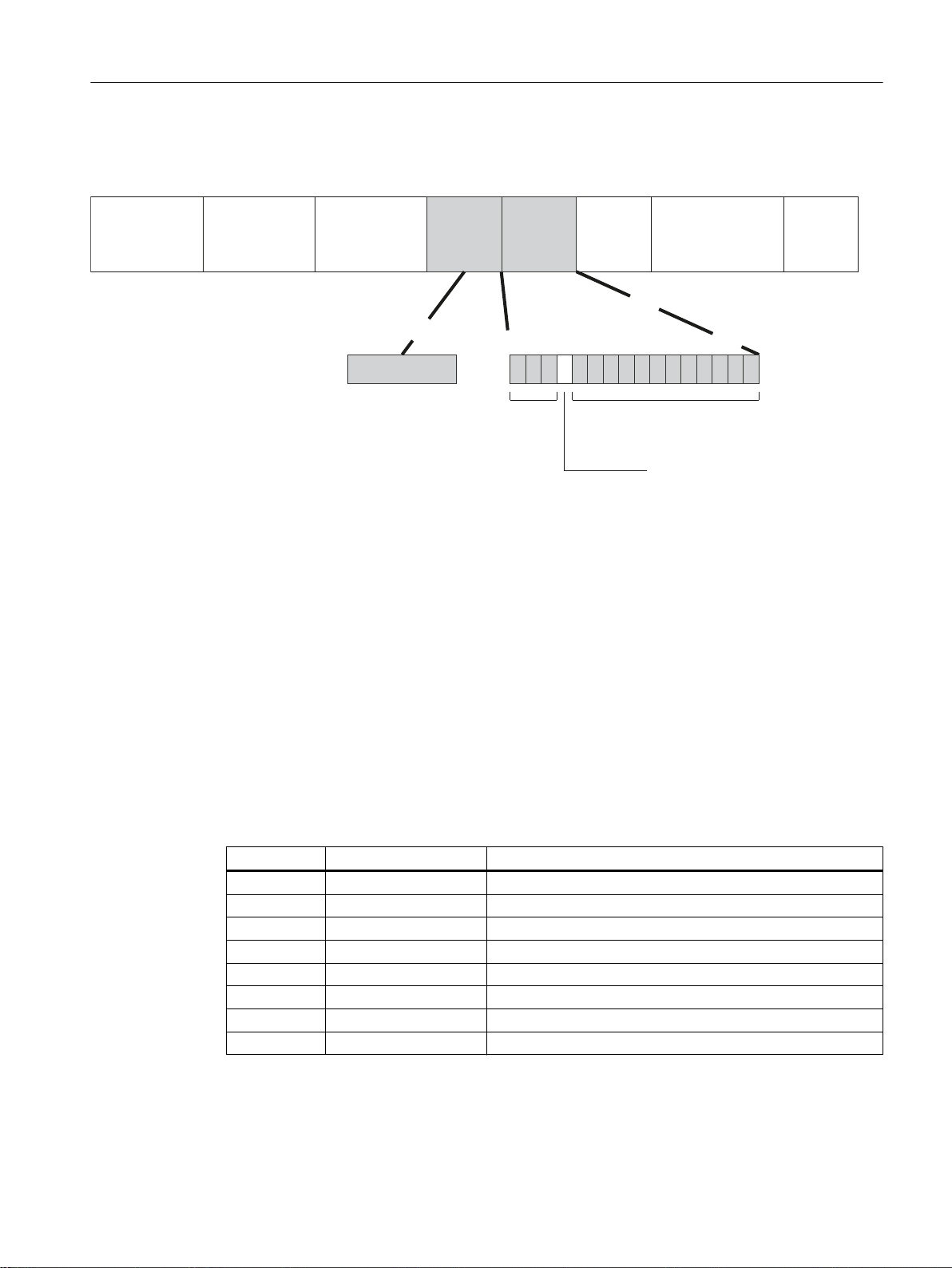
The additional 4 bytes are located in the header of the Ethernet frame between the source
[
3UHDPEOH
E\WHV
'HVWLQDWLRQ
DGGUHVV
E\WHV
6RXUFH
DGGUHVV
E\WHV
73,'
E\WHV
7&,
E\WHV
7\SH
E\WHV
'DWD
aE\WHV
&5&
E\WHV
&),ELW
9/$1,'ELWV
3ULRULW\
ELWV
address and the Ethernet type / length field:
Figure 4-1 Structure of the expanded Ethernet frame
Technical basics
4.4 VLAN
The additional bytes contain the tag protocol identifier (TPID) and the tag control information
(TCI).
Tag protocol identifier (TPID)
The first 2 bytes form the Tag Protocol Identifier (TPID) and always have the value 0x8100.
This value specifies that the data packet contains VLAN information or priority information.
Tag Control Information (TCI)
The 2 bytes of the Tag Control Information (TCI) contain the following information:
QoS Trust
The tagged frame has 3 bits for the priority that is also known as Class of Service (CoS), see
also IEEE 802.1Q.
CoS bits Priority Type of the data traffic
000 0 (lowest) Background
001 1 Best Effort
010 2 Excellent Effort
011 3 Critical Applications
100 4 Video, < 100 ms delay (latency and jitter)
101 5 Voice (language), < 10 ms delay (latency and jitter)
110 6 Internetwork Control
111 7 (highest) Network Control
The prioritization of the data packets is possible only if there is a queue in the components in
which they can buffer data packets with lower priority.
SCALANCE XM-400/XR-500 Web Based Management (WBM)
Configuration Manual, 05/2017, C79000-G8976-C248-12 39

Technical basics
4.4 VLAN
The device has multiple parallel queues in which the frames with different priorities can be
processed. As default, first, the frames with the highest priority are processed. This method
ensures that the frames with the highest priority are sent even if there is heavy data traffic.
Canonical Format Identifier (CFI)
The CFI is required for compatibility between Ethernet and the token Ring.
The values have the following meaning:
Value Meaning
0 The format of the MAC address is canonical. In the canonical representation of the MAC
address, the least significant bit is transferred first. Standard-setting for Ethernet switches.
1 The format of the MAC address is not canonical.
VLAN ID
In the 12-bit data field, up to 4096 VLAN IDs can be formed. The following conventions apply:
VLAN ID Meaning
0 The frame contains only priority information (priority tagged frames) and no valid
VLAN identifier.
1- 4094 Valid VLAN identifier, the frame is assigned to a VLAN and can also include priority
information.
4095 Reserved
4.4.3 Private VLAN
With a private VLAN (PVLAN) you can divide up the layer 2 broadcast domains of a VLAN.
A private VLAN consists of the following units:
● A primary private VLAN (primary PVLAN)
The VLAN that is divided up is called primary private VLAN.
● secondary private VLANs (secondary PVLAN)
Secondary PVLANs exist only within a primary PVLAN. Every secondary PVLAN has a
specific VLAN ID and is connected to the primary PVLAN.
Secondary PVLANs are divided into the following types:
– Isolated Secondary PVLAN
Devices within an isolated secondary PVLAN cannot communicate with each other via
layer 2.
– Community Secondary PVLAN
Devices within a community secondary PVLAN can communicate with each other
directly via layer 2. The devices cannot communicate with devices in other communities
of the PVLAN via layer 2.
SCALANCE XM-400/XR-500 Web Based Management (WBM)
40 Configuration Manual, 05/2017, C79000-G8976-C248-12
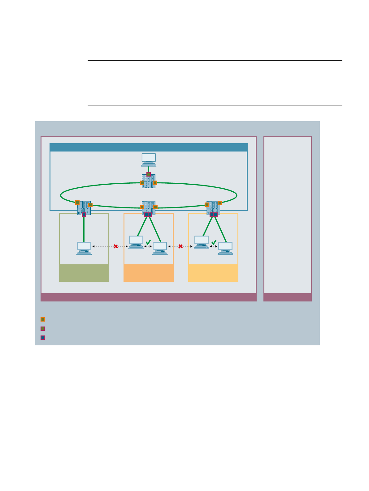
VLAN YPrivate VLAN
Primary PVLAN X
Secondary PVLAN 10
Isolated
Secondary PVLAN 20
Community
Secondary PVLAN 30
Community
/D\HU
Server
PC1
PC2
PC3
PC4
PC5
3URPLVFXRXV3RUW7DJJHG0HPEHU
+RVW3RUW8QWDJJHG0HPEHU
3URPLVFXRXV3RUW8QWDJJHG0HPEHU
Technical basics
4.4 VLAN
Note
VLAN ID with secondary PVLANs
If you use the same VLAN ID for secondary PVLANs on different IE switches, the end devices
in these secondary PVLANs can communicate with other via layer 2 across the different
switches.
In this example, the ports of the IE switches that connect them to other IE switches are
promiscuous ports. These network ports are tagged members in all PVLANs: Primary PVLAN
and all secondary PVLANs.
The ports to which the PCs are connected are host ports. The host ports are all untagged
members in the primary PVLAN and in their secondary PVLAN.
The port to which the server is connected is a promiscuous port. This promiscuous port ports
is an untagged member in all PVLANs: Primary PVLAN and all secondary PVLANs.
In this example all PCs can communicate with the server. The server can communicate with
all PCs. PC1 cannot communicate with any other PC. The PCs within a community secondary
PVLAN can communicate with each other but not with the PCs in another secondary PVLAN.
SCALANCE XM-400/XR-500 Web Based Management (WBM)
Configuration Manual, 05/2017, C79000-G8976-C248-12 41

Customer network A
VLAN ID
Customer network A
VLAN ID
Customer network B
Priority
Customer network B
Priority
Customer network C
untagged
Customer network C
untagged
/D\HU
'DWDWUDIILFWDJJHG
'DWDWUDIILFWXQQHOHG
'DWDWUDIILFXQWDJJHG
$FFHVVSRUW39,'
$FFHVVSRUW39,'
$FFHVVSRUW39,'
Provider network
Technical basics
4.4 VLAN
4.4.4 VLAN tunnel
With the Q-in-Q VLAN Tunnel function it is possible to forward the data traffic from different
customer networks using a VLAN tunnel via a provider network. Every customer network has
the full number of possible VLANs available.
A VLAN tunnel is established between provider switches that are configured at the boundaries
of a provider network. A provider switch has the following types of ports:
● Access port
The provider switch is connected to a customer network via an access port.
– Incoming data traffic
The incoming data traffic at an access port is treated as if it were untagged ①. All
incoming frames are expanded by a tag with the port VID of the access port ②. With
frames that are already tagged, this means they are expanded by a second 802.1Q tag
③ the outer VLAN tag.
– Outgoing data traffic
With outgoing data traffic the outer tag is removed again at an access port.
● Core port
The provider switch is connected to a provider network via a core port.
Core ports are members in the port VLAN of the access port or configured with the port
type "Switch-Port VLAN Trunk".
42 Configuration Manual, 05/2017, C79000-G8976-C248-12
SCALANCE XM-400/XR-500 Web Based Management (WBM)

In this example the data traffic from the customer networks A, B and C is forwarded over the
provider network using a VLAN tunnel. The frames from customer network A are tagged with
a VLAN ID. The frames from customer network B are tagged with a priority. The frames from
customer network C are untagged.
When the frames reach the relevant access port, they are expanded by a tag with the port VID
of the access port and tunneled through the provider network. As soon as the frames leave
the provider network, the outer VLAN tag (PVID) is removed again. The frames are forwarded
in their original form. The priority of the frame is retained.
4.5 Mirroring
The device provides the option of simultaneously channeling incoming or outgoing data
streams via other interfaces for analysis or monitoring. This has no effect on the monitored
data streams. This procedure is known as mirroring. In this menu section, you enable or disable
mirroring and set the parameters.
Mirroring ports
Technical basics
4.5 Mirroring
RSPAN
Mirroring a port means that the data traffic at a port (mirrored port) of the IE switch is copied
to another port (monitor port). You can mirror one or more ports to a monitor port.
If a protocol analyzer is connected to the monitor port, the data traffic at the mirrored port can
be recorded without interrupting the connection. This means that the data traffic can be
investigated without being affected. This is possible only if a free port is available on the device
as the monitor port.
With RSPAN (Remote Switched Port Analyzer) you can forward the data traffic of a mirroring
session to the monitor port via a VLAN. On the RSPAN VLAN, the mirrored data traffic is not
disturbed by other data.
Frames addressed directly to the monitoring source switch cannot be mirrored on the RSPAN
destination port.
SCALANCE XM-400/XR-500 Web Based Management (WBM)
Configuration Manual, 05/2017, C79000-G8976-C248-12 43
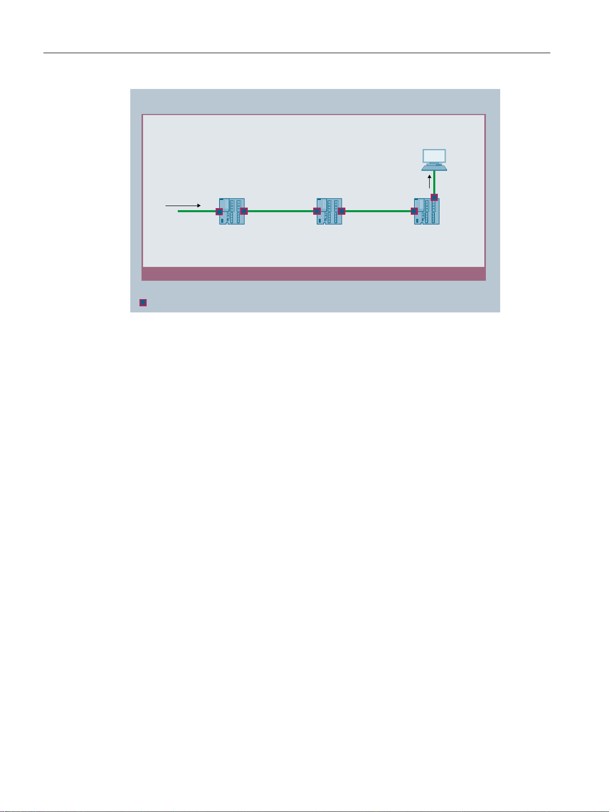
RSPAN-VLAN
/D\HU
Monitoring
Source switch
Destination switchIntermediate
Switch
Protocol
analyzer
563$19/$1
Technical basics
4.6 Redundancy mechanism
Function Extender BUS ANALYZER Agent XM-400
You can use the Function Extender BUS ANALYZER Agent XM-400 with the basic devices
SCALANCE XM-400 as of firmware version 5.1.
The function extender BUS ANALYZER Agent XM-400 is a modular network component with
4 internal monitor ports for port mirroring. Ports of the basic device can be mirrored on the
internal ports of the function extender BUS ANALYZER Agent XM-400 and their data traffic
recorded. You do not need to reserve any ports of the basic device or a port extender for this.
● The mirrored data traffic is available on the management port (M1) of the BUS ANALYZER
Agent XM-400.
● To record the mirrored data traffic, the software BUS ANALYZER SCOPE is used.
4.6 Redundancy mechanism
4.6.1 Spanning Tree
Avoiding loops on redundant connections
The spanning tree algorithm allows network structures to be created in which there are several
connections between two IE switches / bridges. Spanning tree prevents loops being formed
in the network by allowing only one path and disabling the other (redundant) ports for data
traffic. If there is an interruption, the data can be sent over an alternative path. The functionality
of the spanning tree algorithm is based on the exchange of configuration and topology change
frames.
44 Configuration Manual, 05/2017, C79000-G8976-C248-12
SCALANCE XM-400/XR-500 Web Based Management (WBM)

Definition of the network topology using the configuration frames
The devices exchange configuration frames known as BPDUs (Bridge Protocol Data Units)
with each other to calculate the topology. The root bridge is selected and the network topology
created using these frames. BPDUs also bring about the status change of the root ports.
The root bridge is the bridge that controls the spanning tree algorithm for all involved
components.
Once the root bridge has been specified, each device sets a root port. The root port is the port
with the lowest path costs to the root bridge.
Response to changes in the network topology
If nodes are added to a network or drop out of the network, this can affect the optimum path
selection for data packets. To be able to respond to such changes, the root bridge sends
configuration messages at regular intervals. The interval between two configuration messages
can be set with the "Hello Time" parameter.
Keeping configuration information up to date
Technical basics
4.6 Redundancy mechanism
With the "Max Age" parameter, you set the maximum age of configuration information. If a
bridge has information that is older than the time set in "Max Age", it discards the message
and initiates recalculation of the paths.
New configuration data is not used immediately by a bridge but only after the period specified
in the "Forward Delay" parameter. This ensures that operation is only started with the new
topology after all the bridges have the required information.
4.6.1.1 RSTP, MSTP, CIST
Rapid Spanning Tree Protocol (RSTP)
One disadvantage of STP is that if there is a disruption or a device fails, the network needs to
reconfigure itself: The devices start to negotiate new paths only when the interruption occurs.
This can take up to 30 seconds. Fur this reason, STP was expanded to create the "Rapid
Spanning Tree Protocol" (RSTP, IEEE 802.1w). This differs from STP essentially in that the
devices are already collecting information about alternative routes during normal operation
and do not need to gather this information after a disruption has occurred. This means that the
reconfiguration time for an RSTP controlled network can be reduced to a few seconds.
This is achieved by using the following functions:
● Edge ports (end node port)
Edge ports are ports connected to an end device.
A port that is defined as an edge port is activated immediately after connection
establishment. If a spanning tree BPDU is received at an edge port, the port loses its role
as edge port and it takes part in (R)STP again. If no further BPDU is received after a certain
time has elapsed (3 x hello time), the port returns to the edge port status.
● Point-to-point (direct communication between two neighboring devices)
By directly linking the devices, a status change (reconfiguration of the ports) can be made
without any delays.
SCALANCE XM-400/XR-500 Web Based Management (WBM)
Configuration Manual, 05/2017, C79000-G8976-C248-12 45

Technical basics
4.6 Redundancy mechanism
● Alternate port (substitute for the root port)
A substitute for the root port is configured. If the connection to the root bridge is lost, the
device can establish a connection over the alternate port without any delay due to
reconfiguration.
● Reaction to events
Rapid spanning tree reacts to events, for example an aborted connection, without delay.
There is no waiting for timers as in spanning tree.
● Counter for the maximum bridge hops
The number of bridge hops a package is allowed to make before it automatically becomes
invalid.
In principle, therefore with rapid spanning tree, alternatives for many parameters are
preconfigured and certain properties of the network structure taken into account to reduce the
reconfiguration time.
Multiple Spanning Tree Protocol (MSTP)
The Multiple Spanning Tree Protocol (MSTP) is a further development of the Rapid Spanning
Tree Protocol. Among other things, it provides the option of operating several RSTP instances
within different VLANs or VLAN groups and, for example, making paths available within the
individual VLANs that the single Rapid Spanning Tree Protocol would globally block.
Common and Internal Spanning Tree (CIST)
CIST identifies the internal instance used by the switch that is comparable in principle with an
internal RSTP instance.
4.6.2 HRP
HRP - High Speed Redundancy Protocol
HRP is the name of a redundancy method for networks with a ring topology. The switches are
interconnected via ring ports. One of the switches is configured as the redundancy manager
(RM). The other switches are redundancy clients. Using test frames, the redundancy manager
checks the ring to make sure it is not interrupted. The redundancy manager sends test frames
via the ring ports and checks that they are received at the other ring port. The redundancy
clients forward the test frames.
If the test frames of the RM no longer arrive at the other ring port due to an interruption, the
RM switches through its two ring ports and informs the redundancy clients of the change
immediately. The reconfiguration time after an interruption of the ring is a maximum of 300 ms.
Standby redundancy
Standby redundancy is a method with which rings each of which is protected by high-speed
redundancy can be linked together redundantly. In the ring, a master/slave device pair is
configured and these monitor each other via their ring ports. If a fault occurs, the data traffic
SCALANCE XM-400/XR-500 Web Based Management (WBM)
46 Configuration Manual, 05/2017, C79000-G8976-C248-12

Requirements
Technical basics
4.6 Redundancy mechanism
is redirected from one Ethernet connection (standby port of the master or standby server) to
another Ethernet connection (standby port of the slave).
HRP
● HRP is supported in ring topologies with up to 50 devices.
Exceeding this number of devices can lead to a loss of data traffic.
● For HRP, only devices that support this function can be used in the ring.
● Devices that do not support HRP must be linked to the ring using special devices with HRP
capability. Up to the ring, this connection is not redundant.
● All devices must be interconnected via their ring ports. Multimode connections up to 3 km
and single mode connections up to 26 km between two IE switches are possible. At greater
distances, the specified reconfiguration time may be longer.
● A device in the ring must be configured as redundancy manager by selecting the "HRP
manager" setting. On all other devices in the ring, either the "HRP Client" or "Automatic
Redundancy Detection" mode must be activated.
● The standby ports must be disabled in spanning tree.
● You configure HRP in Web Based Management, Command Line Interface or using SNMP.
Standby redundancy
● With standby coupling partners HRP must be set permanently.
● The ports of the standby coupling partners must be disabled in spanning tree.
● You configure standby redundancy in Web Based Management, Command Line Interface
or using SNMP.
4.6.3 MRP
4.6.3.1 MRP - Media Redundancy Protocol
The "MRP" method conforms to the Media Redundancy Protocol (MRP) specified in the
following standard:
IEC 62439‑2 Release 1.0 (2010‑02) Industrial communication networks ‑ High availability
automation networks Part 2: Media Redundancy Protocol (MRP)
The reconfiguration time after an interruption of the ring is a maximum of 200 ms.
SCALANCE XM-400/XR-500 Web Based Management (WBM)
Configuration Manual, 05/2017, C79000-G8976-C248-12 47

S7-400 with
CP 443-1
Redundancy domain
S7-1500 with
CP 1543-1
SIMATIC S7-400
SIMATIC S7-400
SIMATIC S7-300
SCALANCE X208
SCALANCE
X310
SIMATIC
S7-400
PC
PC
Industrial Ethernet (Twisted Pair)
Operator Station
6&$/$1&(
;0
SCALANCE
XB205-3
SIMATIC
S7-1500
SIMATIC
S7-1500
SIMATIC
S7-1200
SIMATIC
S7-1200
Technical basics
4.6 Redundancy mechanism
Topology
The following figure shows a possible topology for devices in a ring with MRP.
Figure 4-2 Example of a ring topology with the MRP media redundancy protocol
The following rules apply to a ring topology with media redundancy using MRP:
● All the devices connected within the ring topology are members of the same redundancy
domain.
● One device in the ring is acting as redundancy manager.
● All other devices in the ring are redundancy clients.
Non MRP-compliant devices can be connected to the ring via a SCALANCE X switch or via a
PC with a CP capable of MRP.
Requirements
Requirements for problem-free operation with the MRP media redundancy protocol are as
follows:
● MRP is supported in ring topologies with up to 50 devices.
Exceeding this number of devices can lead to a loss of data traffic.
● The ring in which you want to use MRP may only consist of devices that support this function.
These include, for example, some of the Industrial Ethernet SCALANCE X switches, some
of the communications processors (CPs) for SIMATIC S7 and PG/PC or non-Siemens
devices that support this function.
48 Configuration Manual, 05/2017, C79000-G8976-C248-12
SCALANCE XM-400/XR-500 Web Based Management (WBM)

See also
Technical basics
4.6 Redundancy mechanism
● All devices must be interconnected via their ring ports.
Multimode connections up to 3 km and single mode connections up to 26 km between two
SCALANCE X IE switches are possible. At greater distances, the specified reconfiguration
time may be longer.
● "MRP" must be enabled for all devices in the ring.
● The connection settings (transmission medium / duplex) must be set to full duplex and at
least 100 Mbps for all ring ports. Otherwise there may be a loss of data traffic.
– STEP 7: Set all the ports involved in the ring to "Automatic settings" in the "Options" tab
of the properties dialog.
– WBM: If you configure with Web Based Management, the ring ports are set automatically
to autonegotiation.
Configuration in STEP 7 (Page 50)
SCALANCE XM-400/XR-500 Web Based Management (WBM)
Configuration Manual, 05/2017, C79000-G8976-C248-12 49

Technical basics
4.6 Redundancy mechanism
4.6.3.2 Configuration in WBM
Role
The choice of role depends on the following use cases:
● You want to use MRP in a ring topology only with Siemens devices:
– For at least one device in the ring select "Automatic Redundancy Detection" or "MRP
Auto Manager".
– For all other devices in the ring select "MRP Client" or "Automatic Redundancy
Detection".
● You want to use MRP in a ring topology that also includes non-Siemens devices:
– For exactly one device in the ring select the role "MRP Auto Manager".
– For all other devices in the ring topology, select the role of "MRP client".
Note
The use of "Automatic Redundancy Detection" is not possible when using non-Siemens
devices.
● You configure the devices in an MRP ring topology partly with WBM and partly with STEP
7:
– With the devices you configure using WBM, select "MRP Client" for all devices.
– With the devices that you configure using STEP 7, select precisely one device as
"Manager" or "Manager (Auto)" and "MRP Client" for all other devices.
Note
If a device is assigned the role of "Manager" with STEP 7, all other devices in the ring must
be assigned the "MRP Client" role. If there is a device with the "Manager" role and a device
with the "Manager (Auto)"/"MRP Auto-Manager" in a ring, this can lead to circulating frames
and therefore to failure of the network.
Configuration
In WBM, you configure MRP on the following pages:
● Configuration (Page 245)
● Ring (Page 284)
4.6.3.3 Configuration in STEP 7
Configuration in STEP 7
To create the configuration in STEP 7, select the parameter group "Media redundancy" on the
PROFINET interface.
SCALANCE XM-400/XR-500 Web Based Management (WBM)
50 Configuration Manual, 05/2017, C79000-G8976-C248-12

Technical basics
4.6 Redundancy mechanism
Set the following parameters for the MRP configuration of the device:
● Domain
● Role
● Ring port
● Diagnostic interrupts
These settings are described below.
Note
Valid MRP configuration
In the MRP configuration in STEP 7, make sure that all devices in the ring have a valid MRP
configuration before you close the ring. Otherwise, there may be circulating frames that will
cause a failure in the network.
One device in the ring needs to be configured as "redundancy manager" and all other devices
in the ring as "clients".
Note
Note factory settings
MRP is disabled and spanning tree enabled for the following brand new IE switches and those
set to the factory settings:
● SCALANCE XB-200 (Ethernet/IP variants)
● SCALANCE XP-200 (Ethernet/IP variants)
● SCALANCE XR-300WG
● SCALANCE XM-400
● SCALANCE XR-500
To load a PROFINET configuration into one of the specified devices, first disable spanning
tree on the device.
Note
Reconfiguration only when the ring is open
First open the ring before you
● change the MRP role or
● reconfigure ring ports
Note
Starting up and restarting
The MRP settings are still effective after a restart of the device or a power failure and hot restart
as long as the power failure does not occur within 90 seconds after the configuration change.
SCALANCE XM-400/XR-500 Web Based Management (WBM)
Configuration Manual, 05/2017, C79000-G8976-C248-12 51

Technical basics
4.6 Redundancy mechanism
Note
Prioritized startup
If you configure MRP in a ring, you cannot use the "prioritized startup" function in PROFINET
applications on the devices involved.
If you want to use the "prioritized startup" function, then disable MRP in the configuration.
In the STEP 7 configuration, set the role of the relevant device to "Not a node in the ring".
Domain
Single MRP rings
If you want to configure a single MRP ring, leave the factory setting "mrpdomain 1" in the
"Domain" drop-down list.
All devices configured in a ring with MRP must belong to the same redundancy domain. A
device cannot belong to more than one redundancy domain in a single ring.
Multiple MRP rings
If you configure multiple single MRP rings, the nodes of the ring will be assigned to the
individual rings with the "Domain" parameter. Set the same domain for all devices within a ring.
Set different domains for different rings. Devices that do not belong to the same ring must have
different domains.
Role
If you want to configure MRP multiple rings, as the central redundancy manager for up to four
rings select a device that is capable of multiple rings. Specify different domains for all ring
instances and assign these to the corresponding ring ports of the redundancy manager.
Configure the other devices as clients. The same domain must be set for all devices within a
ring.
Note
Reconfiguration only when the ring is open!
The choice of role depends on the following use cases.
● You want to use MRP in a topology with one ring only with Siemens devices and without
monitoring diagnostic interrupts:
Assign all devices to the "mrpdomain‑1" domain and the role "Manager (Auto)".
The device that actually takes over the role of redundancy manager, is negotiated by
Siemens devices automatically.
● You want to use MRP in a topology with multiple rings only with Siemens devices and
without monitoring diagnostic interrupts (MRP multiple rings):
– Assign all instances of the device that connects the rings the role of "Manager".
– For all other devices in the ring topology, select the role of "Client".
SCALANCE XM-400/XR-500 Web Based Management (WBM)
52 Configuration Manual, 05/2017, C79000-G8976-C248-12

Technical basics
4.6 Redundancy mechanism
● You want to use MRP in a ring topology that also includes non-Siemens devices or you
want to receive diagnostic interrupts relating to the MRP status from a device (see
"Diagnostic interrupts"):
– Assign precisely one device in the ring the role of "Manager (Auto)".
– For all other devices in the ring topology, select the role of "Client".
● You want to disable MRP:
Select the option "Not node in the ring" if you do not want to operate the device within a
ring topology with MRP.
Note
Role after resetting to factory settings
With brand new Siemens devices and those reset to the factory settings the following MRP
role is set:
● "Manager (Auto)"
CPs
● "Automatic Redundancy Detection"
– SCALANCE X-200
– SCALANCE XC-200
– SCALANCE XB-200 (PROFINET variants)
– SCALANCE XP-200 (PROFINET variants)
– SCALANCE X-300
– SCALANCE X-400
If you are operating a non-Siemens device as the redundancy manager in the ring, this may
cause loss of the data traffic.
MRP is disabled and spanning tree enabled for the following brand new IE switches and
those set to the factory settings:
● SCALANCE XB-200 (Ethernet/IP variants)
● SCALANCE XP-200 (Ethernet/IP variants)
● SCALANCE XR-300WG
● SCALANCE XM-400
● SCALANCE XR-500
Ring port 1 / ring port 2
Here, select the port you want to configure as ring port 1 and ring port 2.
With devices with more than 8 ports, not all ports can be selected as ring port.
SCALANCE XM-400/XR-500 Web Based Management (WBM)
Configuration Manual, 05/2017, C79000-G8976-C248-12 53

Technical basics
4.6 Redundancy mechanism
The drop-down list shows the selection of possible ports for each device type. If the ports are
specified in the factory, the boxes are grayed out.
NOTICE
Ring ports after resetting to factory settings
If you reset to the factory settings, the ring port settings are also reset.
If other ports were used previously as ring ports before resetting, with the appropriate
attachment, a previously correctly configured device can cause circulating frames and
therefore the failure of the data traffic.
Note
Reconfiguration only when the ring is open
First open the ring before you reconfigure the ring ports of a multiple ring manager.
Diagnostic interrupts
Enable the "Diagnostic interrupts" option, if you want diagnostic interrupts relating to the MRP
status on the local CPU to be output.
The following diagnostic interrupts can be generated:
● Wiring or port error
Diagnostic interrupts are generated if the following errors occur at the ring ports:
– Connection abort on a ring port
– A neighbor of the ring port does not support MRP.
– A ring port is connected to a non-ring port.
– A ring port is connected to the ring port of another MRP domain.
● Status change active/passive (redundancy manager only)
If the status changes (active/passive) in a ring, a diagnostics interrupt is generated.
Parameter assignment of the redundancy is not set by STEP 7 (redundancy alternatives)
This option only affects SCALANCE X switches. Select this option if you want to set the
properties for media redundancy using alternative mechanisms such as WBM, CLI or SNMP.
If you enable this option, existing redundancy settings are retained and are not overwritten.
The parameters in the "MRP configuration" box are then reset and grayed out. The entries
then have no meaning.
SCALANCE XM-400/XR-500 Web Based Management (WBM)
54 Configuration Manual, 05/2017, C79000-G8976-C248-12

4.6.4 Standby
SCALANCE XB205-3
as standby master
SCALANCE XB205-3
as standby slave
Operator Station Operator Stations
100 Mbit/s
100 Mbit/s
Industrial Ethernet / PROFINET (Twisted Pair)
S7-400
S7-1500 S7-1500
SCALANCE
XM408-8C
S7-300
IPC
SCALANCE
X204-2
SCALANCE X208
Industrial Ethernet / PROFINET (Fiber Optic)
SCALANCE
XR528-6M
SCALANCE
X308-2
SIMATIC
S7-1200
General
SCALANCE X switches support not only ring redundancy within a ring but also redundant
linking of rings or open network segments (linear bus). In the redundant link, rings are
connected together over Ethernet connections. This is achieved by configuring a master/slave
device pair in one ring so that the devices monitor each other and, in the event of a fault,
redirect the data traffic from the normally used master Ethernet connection to the substitute
(slave) Ethernet connection.
Standby redundancy
Technical basics
4.6 Redundancy mechanism
Figure 4-3 Example of a redundant link between rings
SCALANCE XM-400/XR-500 Web Based Management (WBM)
Configuration Manual, 05/2017, C79000-G8976-C248-12 55

Technical basics
4.6 Redundancy mechanism
For a redundant link as shown in the figure, two devices must be configured as standby
redundancy switches within a network segment. In this case, network segments are rings with
a redundancy manager. Instead of rings, network segments might also be linear.
The two standby redundancy switches connected in the configuration exchange data frames
with each other to synchronize their operating statuses (one device is master and the other
slave). If there are no problems, only the link from the master to the other network segment is
active. If this link fails (for example due to a link-down or a device failure), the slave activates
its link as long as the problem persists.
4.6.5 Link Check
Monitoring optical connections in the ring
On optical connections disturbances are possible in which the optical connection is not
completely interrupted, but frames are lost sporadically. Such problems can, for example, be
caused by defective optical cables, dirty connectors or device defects.
The redundancy manager of an HRP or MRP ring with optical connections detects a “nonrecoverable ring error” with such a disturbance. The redundancy manager cannot eliminate
the disturbance by closing the ring. Closing the ring in this case, would lead to circulating
frames.
With the Link Check function, you can monitor the transmission quality of optical sections within
an HRP or MRP ring, identify disturbed connections and under certain conditions turn them
off. When the disturbed section is turned off, the redundancy manager can close the ring and
restore communication.
How Link Check works
Behavior with an undisturbed connection
If you enable Link Check on two connected ring ports, the two connection partners exchange
Link Check frames cyclically on these ports. The frames received by one connection partner
are sent back to the other.
When the devices receive back the frames they sent from the connection partner, the
connection is prepared for Link Check. The connection partners then increase the send
frequency of the Link Check test frames and the actual connection monitoring is active.
Behavior with a disturbance
When connection monitoring is enabled, you can see the number of sent and received Link
Check test frames on the “Information > Redundancy >Link Check” page. Based on these
statistics you can recognize smaller disturbances for which the disturbance does not yet cause
the transmission line to be closed down by Link Check.
Link Check recognizes a connection as being disturbed and closes it down when too many
test frames are lost within a given period. Link Check uses several intervals to be able to
recognize sudden occurrences of errors as well as a continuous low error rate.
SCALANCE XM-400/XR-500 Web Based Management (WBM)
56 Configuration Manual, 05/2017, C79000-G8976-C248-12

Technical basics
4.7 Link aggregation
A port that was turned off by Link Check must be reset to be able to communicate again. To
do this you have 2 options:
● Pull out the connecting cable and plug it in again.
● Reset the function on both connection partners using the “Reset” button. This must be done
on both devices within 30 s.
Note
When you use the “Reset” button, loops can form temporarily resulting in a loss of data
traffic. The loop is automatically cleared again.
If this is not acceptable for your application, reset Link Check by pulling the cable and
plugging it in again.
After resetting Link Check, the function is restarted on the port and the statistics are reset.
Configuring via a PROFINET IO controller
If MRP is configured via a PROFINET IO controller, you can start the Link Check function for
the optical ring ports of the 1st MRP ring instance using WBM or CLI.
When a new configuration is transferred, Link Check is automatically disabled on all ports that
were not configured as ring ports of the 1st MRP ring instance.
Note
Events relating to the Link Check function are reported only indirectly by PROFINET IO. If the
MRP diagnostics alarms are enabled and a ring port is disabled by LinkCheck, Profinet IO
generates an error message that the connection no longer exists.
4.7 Link aggregation
Link aggregation
With link aggregation, several parallel physical connections with the same transmission speed
are grouped together to form a logical connection with a higher transmission speed. This
method based on IEEE 802.3ad is also known as port trunking or channel bundling.
Link aggregation works only with full duplex connections with the same transmission speed in
point-to-point mode. This achieves multiplication of the bandwidth or transmission speed. If
part of the connection fails, the data traffic is handled via the remaining parts of the connection.
To control and monitor, the Link Aggregation Control Layer (LACL) and the Link Aggregation
Control Protocol (LACP) are used.
SCALANCE XM-400/XR-500 Web Based Management (WBM)
Configuration Manual, 05/2017, C79000-G8976-C248-12 57

Technical basics
4.8 Routing function
4.8 Routing function
Introduction
The term routing describes the specification of routes for communication between different
networks; in other words, how does a data packet from subnet A get to subnet B.
SCALANCE X supports the following routing functions:
● Static routing
With static routing, the routes are entered manually in the routing table.
● Router redundancy
With standardized VRRP (Virtual Router Redundancy Protocol), the availability of important
gateways is increased by redundant routers.
– VRRPv2 (IPv4)
– VRRPv3 (IPv4 / IPv6)
● Dynamic routing
The entries in the routing table are dynamic and are updated continuously. The entries are
created with one of the following dynamic routing protocols:
– OSPFv2 (IPv4)
– OSPFv3 (IPv6)
– RIPv2 (IPv4)
– RIPng (IPv6)
4.8.1 Static routing
The route is entered manually in the routing table. Enter the route in the routing table on the
following pages.
● Layer 3 (IPv4) > Static Routes
● Layer 3 (IPv6) > Static Routes
See also
Static Routes (Page 351)
SCALANCE XM-400/XR-500 Web Based Management (WBM)
58 Configuration Manual, 05/2017, C79000-G8976-C248-12

4.8.2 VRRP
4.8.2.1 VRRPv2
Router redundancy with VRRP
With the Virtual Router Redundancy Protocol (VRRP), the failure of a router in a network can
be countered.
VRRP can only be used with virtual IP interfaces (VLAN interfaces) and not with router ports.
Several VRRP routers in a network segment are put together as a logical group representing
a virtual router (VR). The group is defined using the virtual ID (VRID). Within the group, the
VRID must be the same. The VRID can no longer be used for other groups.
The virtual router is assigned a virtual IP address and a virtual MAC address. One of the VRRP
routers within the group is specified as the master router. The master router has priority 255.
The other VRRP routers are backup routers. The master router assigns the virtual IP address
and the virtual MAC address to its network interface. The master router sends VRRP packets
(advertisements) to the backup routers at specific intervals. With the VRRP packets, the master
router signals that it is still functioning. The master router also replies to the ARP queries.
Technical basics
4.8 Routing function
If the virtual master router fails, a backup router takes over the role of the master router. The
backup router with the highest priority becomes the master router. If the priority of the backup
routers is the same, the higher MAC address decides. The backup router becomes the new
virtual master router.
The new virtual master router adopts the virtual MAC and IP address. This means that no
routing tables or ARP tables need to be updated. The consequences of a device failure are
therefore minimized.
You configure VRRP in "Layer 3 (IPv4) > VRRP (Page 364)".
4.8.2.2 VRRP3
Version 3 of VRRP is based on version 2.
Note
● Enable routing to be able to use VRRPv3.
● You can only use VRRPv3 in conjunction with VLAN interfaces. Router ports are not
supported.
● Simultaneous operation of VRRP and VRRPv3 is not possible.
● VRRPv3 supports IPv4 and IPv6. Both can be configured and operated at the same time
with VRRP3.
You configure VRRPv3 in:
IPv4: Layer 3 (IPv4 )> VRRPv3 (Page 372)
IPv6: Layer 3 (IPv6 )> VRRPv3 (Page 422)
SCALANCE XM-400/XR-500 Web Based Management (WBM)
Configuration Manual, 05/2017, C79000-G8976-C248-12 59

Technical basics
4.8 Routing function
4.8.3 OSPF
4.8.3.1 OSPFv2
Dynamic routing with OSPFv2
OSPF (Open Shortest Path First) is a cost-based routing protocol. To calculate the shortest
and most cost-effective route, the Short Path First algorithm by Dijkstra is used. OSPF was
developed by the IETF (Internet Engineering Task Force).
You configure OSPFv2 in "Layer 3 (IPv4) > OSPFv2 (Page 380)".
OSPFv2 divides an autonomous system (AS) into different areas.
Areas in OSPF
The following areas exist:
● Backbone
The backbone area is area 0.0.0.0. All other areas are connected to this area. The backbone
area is connected either directly or via virtual connections with other areas.
All routing information is available in the backbone area. As a result, the backbone area is
responsible for forwarding information between different areas.
Routers of OSPF
● Stub Area
This area contains the routes within its area within the autonomous system and the standard
route out of the autonomous system. The destinations outside this autonomous system are
assigned to the standard route.
● Totally Stubby Area
This area knows only the routes within its area and the standard route out of the area.
● Not So Stubby Area (NSSA)
This area can forward (redistribute) packets from other autonomous systems into the areas
of its own autonomous system. The packets are further distributed by the NSSA router.
OSPF distinguishes the following router types:
● Internal router (IR)
All OSPF interfaces of the router are assigned to the same area.
● Area Border Router (ABR)
The OSPF interfaces of the router are assigned to different areas. One OSPF interface is
assigned to the backbone area. Where possible, routes are grouped together.
● Backbone Router (BR)
At least one of the OSPF interfaces is assigned to the backbone area.
● Autonomous System Border Router (ASBR)
One interface of the router is connected to a different AS, for example an AS that uses the
routing protocol RIP.
SCALANCE XM-400/XR-500 Web Based Management (WBM)
60 Configuration Manual, 05/2017, C79000-G8976-C248-12

Virtual connection
%5
,5
,5
$%5
$%5
166$
$6%5
$6%5
$%5
$%5
6WXE$UHD
166$
$UHD
6WXE$UHD
6WXE$UHD
,5
'5
%DFNERQH
$UHD
$%5
LSA types
Technical basics
4.8 Routing function
Each area must be connected to the backbone area. In some situations a direct physical
connection is not possible. In this case, a router of the relevant area must be connected to a
backbone router via a virtual connection.
Within the autonomous system, packets are exchanged that contain information about the
connections of a router and the connection status message. The packets are also known as
LSAs (Link State Advertisements). The LSAs are always sent from the router to the neighbor
router.
If there are changes in the network, LSAs are sent to all routers in the network. The information
depends on the LSA type.
SCALANCE XM-400/XR-500 Web Based Management (WBM)
Configuration Manual, 05/2017, C79000-G8976-C248-12 61

Technical basics
4.8 Routing function
Router LSA (LSA Type 1)
The LSA Type 1 is only sent within an area. For each active connection of the router
that belongs to the area in consideration, an LSA Type 1 is generated. The LSA Type 1
contains information about the status and the costs of the connection, for example IP
address, network mask, network type
Network LSA (LSA Type 2)
The LSA Type 2 is sent only within an area. For each network that belongs to the relevant
area, the router generates an LSA Type 2. If several routers are interconnected in a
network, the LSA Type 2 is sent by the designated router (DR). The LSA Type 2 includes
the network address, the network mask and a list of routers that are connected to the
network
Summary LSA (LSA Type 3 / LSA Type 4)
The Summary LSA is generated by the area border router and sent into the area. The
Summary LSA contains information about routes outside the area but inside the AS.
Where possible, the routes are grouped together.
● Summary LSA (LSA Type 3)
The LSA Type 3 describes the routes to the networks and advertises the standard
route to the areas.
● AS Summary LSA (LSA Type 4)
The LSA Type 4 describes the routes to the ASBR.
External LSA (LSA Type 5 / LSA Type 7)
The External LSA is generated by the ASBR. The LSA type depends on the area.
● AS External LSA (LSA Type 5)
The LSA Type 5 is sent by the AS border router into the areas of the autonomous
system except the Stub and NSSA areas. The LSA contains information about routes
to a network in another AS. The routes are either created manually or learned
externally. The ASBR uses LSA Type 5 to distribute standard routes to the backbone
area.
● NSSA External LSA (LSA Type 7)
The LSA Type 7 is generated by the AS border router of an NSSA. The router is also
known as the NSSA ASBR. The LSA Type 7 is sent only within the NSSA. If the P
bit in LSA Type 7 = 1, these LSAs are converted to LSA Type 5 by the ABR and sent
to the backbone area.
SCALANCE XM-400/XR-500 Web Based Management (WBM)
62 Configuration Manual, 05/2017, C79000-G8976-C248-12

Establishing the neighborhood
The router runs through the following statuses to establish a connection to the neighbor router.
1. Attempt state / Init state
The router activates OSPF and begins to send and receive Hello packets. Based on the
received Hello packets, the router learns which OSPF routers are in its vicinity. The router
checks the content of the Hello packet. The Hello packet also contains the list of the
neighbor routers (neighbor table) of the "sender".
2. Two way state
If, for example, the ID of the area, the area type and the settings for the times match, a
connection (adjacency) can be established to the neighbor. In a point-to-point network, the
connection is established directly. If several neighbor routers can be reached in a network,
the designated router (DR) and the designated backup router (DBR) are identified based
on Hello packets. The router with the highest router priority becomes the designated router.
If two routers have the same router priority, the router with the highest router ID becomes
the designated router. The router establishes a connection to the designated router.
3. Exchangestart state
The neighbor routers decide which router starts communication. The router with the higher
router ID becomes the designated router.
Technical basics
4.8 Routing function
4. Exchange state
The neighbor routers send packets that describe the content of their neighborhood
database. The neighborhood database (link state database - LSDB) contains information
on the topology of the network.
5. Loading state
The router completes the received information. If the router still has questions relating to
the status of a specific connection, it sends a link state request. The neighbor router sends
a response (link state update). The response contains a suitable LSA. The router confirms
receipt of the response (link state acknowledge).
6. Full State
The information exchange with the neighbor router is completed. The neighborhood
database of the neighbor router is the same. Based on the Short Path First algorithm, the
router calculates a route to every destination. The route is entered in the routing table.
Check the neighborhood
The Hello packets are only used to establish the neighborhood relations. Hello packets are
used to check the connection to the neighbor router by sending them cyclically. If no Hello
packet is received within a certain interval (dead interval), the connection to the neighbor is
marked as "down". The relevant entries are deleted.
Updating the neighborhood database
Once the neighborhood database is established, LSAs are sent to all routers in the network if
there are changes in the topology.
SCALANCE XM-400/XR-500 Web Based Management (WBM)
Configuration Manual, 05/2017, C79000-G8976-C248-12 63

Technical basics
4.8 Routing function
4.8.3.2 OSPFv3
Version 3 of OSPF is based on version 2 and is only used with IPv6. A large part of the routing
mechanisms was adopted. OSPFv3 is defined in the RFCs 2740 and 5340.
You configure OSPFv3 under "Layer 3 (IPv6) > OSPFv3".
The following has not changed:
● The statuses that a router runs through to establish a connection to the neighbor router.
● The areas : Backbone, Stub Area, Totally Stubby Area, Not So Stubby Area (NSSA)
● The router types: Internal Router (IR), Area Border Router (ABR), Backbone Router (BR),
Autonomous System Area Border Router (ASBR), Designated Router (DR)
● The router ID, the area ID and the ID of the LSA are entered in the IPv4 address format:
x.x.x.x
What has changed?
Terms
The terms network or subnet are replaced by link.
Authentication
The authentication was removed. Instead OSPFv3 uses IPsec, that is implemented in IPv6.
Neighbor routers
The neighbor routers are identified via the router ID.
Neighbor database
The neighbor database (link state database - LSDB) is divided into different areas of
application:
● Link scope LSDB
Contains the link LSA
● Area scope LSDB
contains the following LSAs
– Router LSA
– Network LSA
– Inter-area prefix LSA
– Inter area router LSA
– Intra area prefix LSA
● AS scope LSDB
Contains the AS external LSA
SCALANCE XM-400/XR-500 Web Based Management (WBM)
64 Configuration Manual, 05/2017, C79000-G8976-C248-12

LSA types
Two new LSA types were defined for OSPFv3.
OSPFv2 OSPFv3 Who Within Description
1 Router LSA 0x2001 Router
LSA
2 Network LSA 0x2002 Network
LSA
3 Summary
LSA
4 AS Summary
LSA
5 AS External
LSA
7 NSSA Exter‐
nal LSA
0x2008 Link LSA every
0x2003 Inter-area
prefix LSA
0x2004 Inter-Area
Router
LSA
0x4005 AS Exter‐
nal LSA
0x2007 Type 7
LSA
0x2009 Intra area
prefix LSA
every
router
DR Area No longer contains address information. This is contained in
ABR Area Same function as in OSPFv2, simply renamed
ABR Area Same function as in OSPFv2, simply renamed
ASBR AS Same function as in OSPFv2, simply renamed
NSSA
ASBR
router
every
router
Area No longer contains address information. This is contained in
the new LSA type 2009.
the new LSA type 2009.
NSSA Same function as in OSPFv2, simply renamed
Link The LSA is sent by the router to every router linked to it. The
LSA contains the link local address of the router and a list
with IPv6 prefixes configured on the link.
Area The LSA is sent only within an area. The LSA contains the
IPv6 prefixes connected to the router or network.
Technical basics
4.8 Routing function
In contrast to OSPFv2, OSPFv3 can forward unknown LSA types. Previously these were
deleted and not distributed further.
4.8.4 RIP
4.8.4.1 RIPv2
Dynamic routing with RIPv2
The Routing Information Protocol (RIPv2) is used to create routing tables automatically. RIPv2
is used in autonomous systems (AS) with a maximum of 15 routers. It is based on the DistanceVector algorithm.
RIPv2 was developed by the IETF (Internet Engineering Task Force) and is described in RFC
2453.
You configure RIPv2 in "Layer 3 (IPv4) > RIPv2".
Setting up a routing table
Since a router initially only knows its directly connected networks, it sends a request to its direct
neighbor routers. As the reply, it receives the routing tables of the neighbor routers. Based on
the information it receives, the router set up its own routing table.
The routing table contains entries for all possible destinations. Each entry includes the distance
to the destination and the first router on the route.
SCALANCE XM-400/XR-500 Web Based Management (WBM)
Configuration Manual, 05/2017, C79000-G8976-C248-12 65

Technical basics
4.8 Routing function
The distance is also known as the metric. This indicates the number of routers to be passed
through on the route to the destination (hop count). The maximum distance is 15 routers (hops).
Updating the routing table
Once the routing table is set up, the router sends its routing table to each direct neighbor router
via the UDP port 520 at intervals of 30 seconds.
The router compares new routing information with its existing routing table. If the new
information includes shorter routes, the existing routes are overwritten. The router only keeps
the shortest route to a destination.
Checking neighbor routers
If a router does not receive messages from a neighbor router for longer than 180 seconds, it
marks the router as being invalid. The router assigns the metric 16 for the neighbor router.
4.8.4.2 RIPng
4.8.5 PIM
RIPng (RIP next generation) is only used with IPv6 and is defined in RFC 2080. As with RIP
(IPv4), RIPng is based on the distance vector algorithm of Bellman-Ford.
In contrast to RIPv2, RIPng is activated directly on the layer 3 interface (VLAN interface / router
port) and not globally on the device.
RIPng uses the UDP port 521 and RIP the UDP port 520.
You configure RIPng in "Layer 3 (IPv6) > RIPng".
Protocol Independent Multicast (PIM) allows the routing of multicast packets, regardless of the
routing protocol such as OSPFv2 or static routing (IPv4). PIM expands the routing information
of the unicast routing protocol active on the router with additional information for multicast
operation.
Requirements for PIM:
● IGMP is enabled on the first hop and last hop of the routing topology.
● PIM is enabled on all routers of the routing topology.
● There is at least one rendezvous point (RP).
● In every subnet there is a designated router (DR).
● The DR must also be the IGMP querier.
PIM network
PIM operates in the sparse mode designed for networks with a low node density.
SCALANCE XM-400/XR-500 Web Based Management (WBM)
66 Configuration Manual, 05/2017, C79000-G8976-C248-12

Technical basics
4.8 Routing function
Sparse mode (SM)
If a router receives a multicast, it sends this information to the rendezvous point (RP). A device
that wants to receive a multicast sends an IGMP Join to the routers in its subnet. The
designated router (DR) of the network sends this request to the RP. The RP therefore has the
unicast address of the sender and a unicast address for the recipient, that of the DR.
In Sparse mode between the sender and recipient the shortest path is selected based on the
routing table and the information can be sent.
Bidirectional multicast and designated forwarder
The "Bidirectional multicast" functionality is a variant of the Sparse mode in which the
information between sender and recipient is always sent via the rendezvous point.
In Bidirectional multicast the DR is replaced by the designated forwarder (DF). When the DF
receives an IGMP Join, it sends a (*, G) message to the RP. The RP replaces the * with the
source and so establishes the connection. Only the DF forwards the multicast.
Rendezvous point (RP) and bootstrap router (BSR)
The rendezvous point manages the information about the sender and recipient: You can create
RPs statically or define RP candidates.
When you define RP candidates you require a bootstrap router. The BSR coordinates the RP
candidates and decides on an RP. You define BSR candidates of which one becomes the
bootstrap router.
BSR border
With the "BSR border" function you can divide a PIM network into domains. There is no BSR
communication between the PIM domains so a BSR is selected in every domain. The BSR of
the domain selects an RP for the domain.
MSDP
The RPs communicate beyond PIM domain boundaries using MSDP and synchronize the
multicast groups they receive. This means that a device in domain A can receive a multicast
although the information about the sender is managed by the RP in domain B.
Source specific multicast (SSM)
PIM source specific multicast is a further variant of Sparse mode that manages without
rendezvous points. Via IGMPv3, the recipient directly informs the router of the source and the
multicast it would like to receive.
SCALANCE XM-400/XR-500 Web Based Management (WBM)
Configuration Manual, 05/2017, C79000-G8976-C248-12 67

VLAN 1 VLAN 3
VLAN 4
VLAN 2
/D\HU
Unicast routing topology
Source
Recipient
Rendezvous point
IGMP querier and DR
0XOWLFDVWJURXS
Technical basics
4.9 NAT/NAPT
Example
In this example the source sends a multicast to the connected router. The router sends this
information to the rendezvous point.
The recipient sends an IGPM Join to its IGMP querier and designated router. The DR forwards
the request to the RP.
Based on the routing table, the shortest path is selected for the multicast.
4.9 NAT/NAPT
Note
NAT/NAPT is possible only on layer 3 of the ISO/OSI reference model. To use the NAT
function, the networks must use the IP protocol.
When using the ISO protocol that operates at layer 2, it is not possible to use NAT.
In Network Address Translation (NAT) IP subnets are divided into "Inside" and "Outside". The
division is from the perspective of a NAT interface. All networks reachable via the NAT interface
68 Configuration Manual, 05/2017, C79000-G8976-C248-12
SCALANCE XM-400/XR-500 Web Based Management (WBM)

*HU¦W
VLAN Y: 10.0.0.0/24
2XWVLGH
VLAN X: 192.168.16.0/24
,QVLGH
3&3&
/D\HU
Technical basics
4.9 NAT/NAPT
itself count as "Outside" for this interface. All networks reachable via other IP interfaces of the
same device count as "Inside" for the NAT interface.
If there s routing via the NAT interface, the source or destination IP addresses of the transferred
data packets are changed at the transition between "Inside" and "Outside". Whether or not the
source or destination IP address is changed depends on the communications direction. It is
always the IP address of the communications node that is located "Inside" that is adapted.
Depending on the perspective the IP address of a communications node is always designated
as "Local" or "Global".
Perspective
Local Global
Position Inside An actual IP address that is as‐
signed to a device in the internal
network. This address cannot be
reached from the external network.
Outside An actual IP address that is assigned to a device in the external network.
Since only "Inside" addresses are converted, there is no distinction
made between outside local and outside global.
An IP address at which an internal
device can be reached from the
external network.
Example
In the example two IP subnets are connected together via an IE switch. The division is from
the perspective of the NAT interface 10.0.0.155. The communication of PC2 with PC1 is
implemented via NAT/NAPT.
The actual IP address of PC1 (inside local) is implemented statically with NAT. For PC2, PC1
can be reached at the inside global address.
Perspective
Local Global
Position Inside 192.168.16.150 10.0.0.7
Outside 10.0.0.10
SCALANCE XM-400/XR-500 Web Based Management (WBM)
Configuration Manual, 05/2017, C79000-G8976-C248-12 69

Technical basics
4.9 NAT/NAPT
The actual IP address of PC1 (inside local) is implemented with NAPT (Network Address and
Port Translation).. For PC2, PC1 can be reached at the inside global address.
Computing capacity
Due to the load limitation of the CPU packet receipt of the device is limited to 300 packets a
second. This corresponds to a maximum data through of 1.7 Mbps. This load limitation does
not apply per interface but generally for all packets going the CPU.
The entire NAT communication runs via the CPU and therefore represents competition for IP
communication going to the CPU, e.g. WBM and Telnet.
Note that a large part of the computing capacity is occupied if you use NAT. This can slow
down access via Telnet or WBM.
Perspective
Local Global
Position Inside 192.168.16.150:80 10.0.0.7:80
Outside 10.0.0.10:1660
NAT
NAPT
With Network Address Translation (NAT), the IP address in a data packet is replaced by
another. NAT is normally used on a gateway between an internal network and an external
network.
With source NAT, the inside local source address of an IP packet from a device in the internal
network is rewritten by a NAT device to an inside global address at the gateway.
With destination NAT, the inside global source address of an IP packet from a device in the
external network is rewritten by a NAT device to an inside local address at the gateway.
To translate the internal into the external IP address and back, the NAT device maintains a
translation list. The address assignment can be dynamic or static. You configure NAT in "Layer
3 (IPv4) > NAT (Page 345)".
In "Network Address Port Translation" (NAPT), several internal source IP addresses are
translated into the same external IP address. To identify the individual nodes, the port of the
internal device is also stored in the translation list of the NAT device and translated for the
external address.
If several internal devices send a query to the same external destination IP address via the
NAT device, the NAT device enters its own external source IP address in the header of these
forwarded frames. Since the forwarded frames have the same external source IP address, the
NAT device assigns the frames to the devices using a different port number.
If a device from the external network wants to use a service in the internal network, the
translation list for the static address assignment needs to be configured. You configure NAPT
in "Layer 3 (IPv4) > NAT > NAPT (Page 349)".
SCALANCE XM-400/XR-500 Web Based Management (WBM)
70 Configuration Manual, 05/2017, C79000-G8976-C248-12

NAT/NAPT and IP routing
You can enable NAT/NAPT and IP routing at the same time. In this case, you need to regulate
the reachability of internal addresses from external networks with ACL rules.
Technical basics
4.9 NAT/NAPT
SCALANCE XM-400/XR-500 Web Based Management (WBM)
Configuration Manual, 05/2017, C79000-G8976-C248-12 71

Technical basics
4.9 NAT/NAPT
SCALANCE XM-400/XR-500 Web Based Management (WBM)
72 Configuration Manual, 05/2017, C79000-G8976-C248-12

Configuring with Web Based Management
5.1 Web Based Management
How it works
The device has an integrated HTTP server for Web Based Management (WBM). If a device
is addressed using an Internet browser, it returns HTML pages to the client PC depending on
the user input.
The user enters the configuration data in the HTML pages sent by the device. The device
evaluates this information and generates reply pages dynamically.
The advantage of this method is that only an Internet browser is required on the client.
Note
Secure connection
WBM also allows you to establish a secure connection via HTTPS.
Use HTTPS for protected transfer of your data. If you wish to access WBM only via a secure
connection, activate the option "HTTPS Server only" under "System > Configuration".
5
Requirements
WBM display
● The device has an IP address.
● There is a connection between the device and the client PC. With the ping command, you
can check whether or not a device can be reached.
● Access using HTTPS is enabled.
● JavaScript is activated in the Internet browser.
● The Internet browser must not be set so that it reloads the page from the server each time
the page is accessed. The updating of the dynamic content of the page is ensured by other
mechanisms. In the Internet Explorer, you can make the appropriate setting in the "Options
> Internet Options > General" menu in the section "Browsing history" with the "Settings"
button. Under "Check for newer versions of stored pages:", select "Automatically".
● If a firewall is used, the relevant ports must be opened.
– For access using HTTP: TCP port 80
– For access using HTTPS: TCP port 443
SCALANCE XM-400/XR-500 Web Based Management (WBM)
Configuration Manual, 05/2017, C79000-G8976-C248-12 73

Configuring with Web Based Management
5.2 Login
The display of the WBM was tested with the following desktop Internet browsers:
● Microsoft Internet Explorer 11
● Mozilla Firefox 45 ESR
● Google Chrome V57
Note
Compatibility view
In Microsoft Internet Explorer, disable the compatibility view to ensure correct display and to
allow problem-free configuration using WBM.
Display of the WBM on mobile devices
For mobile devices, the following minimum requirements must be met:
Resolution Operating system
960 x 640 pixels Android as of version 4.2.1
iOS as of version 6.0.2
Tested with the following Internet browsers for mobile devices:
● Apple Safari as of version 8 on iOS as of V8.1.3 (iPad Mini Model A1432)
● Google Chrome as of version 40 on Android as of version 5.0.2 (Nexus 7C Asus)
● Mozilla Firefox as of version 35 on Android as of version 5.0.2 (Nexus 7C Asus)
Note
Display of the WBM and working with it on mobile devices
The display on the WBM pages and how you work with them on mobile devices may differ
compared with the same pages on desktop devices. Some pages also have an optimized
display for mobile devices.
5.2 Login
Establishing a connection to a device
Follow the steps below to establish a connection to a device using an Internet browser:
1. There is a connection between the device and the client PC. With the ping command, you
can check whether or not a connection exists.
2. In the address box of the Internet browser, enter the IP address or the URL of the device.
If there is a problem-free connection to the device, the logon page of Web Based
Management (WBM)is displayed.
SCALANCE XM-400/XR-500 Web Based Management (WBM)
74 Configuration Manual, 05/2017, C79000-G8976-C248-12

Logging on using the Internet browser
Selecting the language of the WBM
1. From the drop-down list at the top right, select the language version of the WBM pages.
2. Click the "Go" button to change to the selected language.
Note
Available languages
As of version 5.0 English and German are available. Other languages will follow in a later
version.
Configuring with Web Based Management
5.2 Login
Logon with HTTP
There are two ways in which you can log on via HTTP. You either use the logon option in the
center of the browser window or the logon option in the upper left area of the browser window.
SCALANCE XM-400/XR-500 Web Based Management (WBM)
Configuration Manual, 05/2017, C79000-G8976-C248-12 75

Configuring with Web Based Management
5.2 Login
The following steps apply when logging on, whichever of the above options you choose:
1. "Name" input box:
– When you log in for the first time or following a "Restore Factory Defaults and Restart",
enter the user preset in the factory "admin".
With this user account, you can change the settings of the device (read and write access
to the configuration data).
Note
Default user "user" set in the factory
As of firmware version 6.0 the default user set in the factory "user" is no longer available
when the product ships.
If you update a device to the firmware V6.0 the default user set in the factory "user" is
initially still available. If you reset the device to the factory settings ("Restore Factory
Defaults and Restart") the default user set in the factory "user" is deleted.
You can create users with the role "user".
– Enter the user name of the created user account. You configure local user accounts
and roles in "Security > Users".
Logon with HTTPS
2. "Password" input box:
– When you log in for the first time or following a "Restore Factory Defaults and Restart",
enter the password of the default user preset in the factory "admin": "admin".
– Enter the password of the relevant user account.
3. Click the "Login" button or confirm your input with "Enter".
When you log in for the first time or following a "Restore Factory Defaults and Restart", with
the preset user "admin" you will be prompted to change the password.
The new password must meet the following password policies:
– Password length: at least 8 characters, maximum 128 characters.
– at least 1 uppercase letter
– at least 1 special character
– at least 1 number
You need to repeat the password as confirmation. The password entries must match.
Click the "Set Values" button to complete the action and activate the new password.
Once you have logged in successfully, the start page appears.
Web Based Management also allows you to connect to the device over the secure connection
of the HTTPS protocol. Follow these steps:
1. Click on the link "Switch to secure HTTP" on the login page or enter "https://" and the IP
address of the device in the address box of the Internet browser.
2. Check the displayed certificate warning and confirm it if applicable.
The logon page of Web Based Management appears.
SCALANCE XM-400/XR-500 Web Based Management (WBM)
76 Configuration Manual, 05/2017, C79000-G8976-C248-12

Configuring with Web Based Management
5.2 Login
3. "Name" input box:
– When you log in for the first time or following a "Restore Factory Defaults and Restart",
enter the user preset in the factory "admin".
With this user account, you can change the settings of the device (read and write access
to the configuration data).
Note
Default user "user" set in the factory
As of firmware version 6.0 the default user set in the factory "user" is no longer available
when the product ships.
If you update a device to the firmware V6.0 the default user set in the factory "user" is
initially still available. If you reset the device to the factory settings ("Restore Factory
Defaults and Restart") the default user set in the factory "user" is deleted.
You can create users with the role "user".
– Enter the user name of the created user account. You configure local user accounts
and roles in "Security > Users".
4. "Password" input box:
– When you log in for the first time or following a "Restore Factory Defaults and Restart",
enter the password of the default user preset in the factory "admin": "admin".
– Enter the password of the relevant user account.
5. Click the "Login" button or confirm your input with "Enter".
When you log in for the first time or following a "Restore Factory Defaults and Restart", with
the preset user "admin" you will be prompted to change the password.
The new password must meet the following password policies:
– Password length: at least 8 characters, maximum 128 characters.
– at least 1 uppercase letter
– at least 1 special character
– at least 1 number
You need to repeat the password as confirmation. The password entries must match.
Click the "Set Values" button to complete the action and activate the new password.
Once you have logged in successfully, the start page appears.
SCALANCE XM-400/XR-500 Web Based Management (WBM)
Configuration Manual, 05/2017, C79000-G8976-C248-12 77

Configuring with Web Based Management
5.3 The "Information" menu
5.3 The "Information" menu
5.3.1 Start page
View of the Start page
When you enter the IP address of the device, the start page is displayed after a successful
login. You cannot configure anything on this page.
General layout of the WBM pages
The following areas are generally available on every WBM page:
● Selection area (1): Top area
● Display area (2): Top area
● Navigation area (3): Left-hand area
● Content area (4): Middle area
SCALANCE XM-400/XR-500 Web Based Management (WBM)
78 Configuration Manual, 05/2017, C79000-G8976-C248-12

Selection area (1)
Configuring with Web Based Management
5.3 The "Information" menu
The following is available in the selection area:
● Logo of Siemens AG
When you click on the logo, you arrive at the Internet page of the corresponding basic
device in Siemens Industry Online Support.
● Display of: "System Location / System Name"
– System location" contains the location of the device.
With the settings when the device ships, the in-band port IP address of the device is
displayed.
– "System Name" is the device name.
With the settings when the device ships, the device type is displayed.
You can change the content of this display with "System > General > Devices".
● Drop-down list for language selection
● System date and system time with status display
You can change the content of this display with "System > System Time.
If the system time is not set, the status is
. If the system time is configured, but the system
time cannot be synchronized, a yellow warning triangle can be seen. Check whether the
time server can be reached. If necessary adapt your configuration. If the system time is set
and/or can be synchronized, the status is .
Display area (2)
In the upper part of the display area, you can see the full title of the currently selected menu
item.
In the lower part of the display area, you will find the following:
● Logout
You can log out from any WBM page by clicking the "Logout" link.
● LED simulation
Each component of a device has one or more LEDs that provide information on the
operating state of the device. Depending on its location, direct access to the device may
not always be possible. Web Based Management therefore displays simulated LEDs.
Unoccupied slots or unused connectors are displayed as gray LEDs. The meaning of the
LED displays is described in the operating instructions.
If you click the simulated "SELECT/SET" button, you can change the display mode (LEDs
DM or D1/D2).
If you click this button, you open the window for the LED simulation. You can show this
window during a change of menu and move it as necessary. To close the LED simulation,
click the "Close" button in the LED simulation window.
● Help
When you click this button, the help page of the currently selected menu item is opened in
a new browser window.
The help page contains a description of the content area. Under certain circumstances,
options are described that are not available on the device.
SCALANCE XM-400/XR-500 Web Based Management (WBM)
Configuration Manual, 05/2017, C79000-G8976-C248-12 79

Configuring with Web Based Management
5.3 The "Information" menu
● Print
Print If you click this button, a popup window opens. The popup window contains a view of
the page content optimized for printers.
Note
Printing larger tables
If you want to print large tables, please use the "Print preview" function of your Internet
browser.
● Favorites
When the product ships, the button is disabled on all pages .
If you click this button, the symbol changes and the currently open page or currently
open tap is marked as favorite. Once you have enabled the button once, the navigation
area is divided into two tabs. The first tab "Menu" contains all the available menus as
previously. The second tab "Favorites" contains all the pages/tabs that you selected as
favourites. On the "Favorites" tab the pages/tabs are arranged according to the structure
in the "Menu" tab.
If you disable all the favorites you have created, the "Favorites" is removed again.
Navigation area (3)
In the navigation area, you have various menus available. Click the individual menus to display
the submenus. The submenus contain pages on which information is available or with which
you can create configurations. These pages are always displayed in the content area.
If you have created favorites, the navigation area is divided into two tabs: "Menu" and
"Favorites".
SCALANCE XM-400/XR-500 Web Based Management (WBM)
80 Configuration Manual, 05/2017, C79000-G8976-C248-12

Content area (4)
Configuring with Web Based Management
5.3 The "Information" menu
The content area shows a graphic of the device. The graphic is dynamic. The basic device is
always shown. If extenders/media modules are connected to the basic device, these are also
shown.
Figure 5-1 Example of a device graphic: SCALANCE XM416-4C with one port extender PE408
The following is displayed below the device graphic:
● PROFINET Name of Station
Shows the PROFINET device name.
● System Name
Shows the name of the device.
● Device Type
Shows the type designation of the device.
● PROFINET AR Status
Shows the PROFINET IO application relation status.
– Online
There is a connection to a PROFINET controller. The PROFINET controller has
downloaded its configuration data to the device. The device can send status data to the
PROFINET controller.
In this status, the parameters set via the PROFINET controller cannot be configured on
the device.
– Offline
There is no connection to a PROFINET controller.
● Power Supply 1 / Power Supply 2
– Up
Power supply 1 or 2 is applied.
– Down
Power supply 1 or 2 is not applied or is below the permitted voltage.
SCALANCE XM-400/XR-500 Web Based Management (WBM)
Configuration Manual, 05/2017, C79000-G8976-C248-12 81

Configuring with Web Based Management
5.3 The "Information" menu
● PLUG Configuration
Shows the status of the configuration data on the PLUG, refer to the section "System >
PLUG > PLUG Configuration".
● PLUG License
Shows the status of the license on the PLUG, refer to the section "System >PLUG > PLUG
License".
● Fault Status
Shows the fault status of the device.
Buttons you require often
The pages of the WBM contain the following standard buttons:
● Refresh the display with "Refresh"
Web Based Management pages that display current parameters have a "Refresh" button
at the lower edge of the page. Click this button to request up-to-date information from the
device for the current page.
Note
If you click the "Refresh" button, before you have transferred your configuration changes
to the device using the "Set Values" button, your changes will be deleted and the previous
configuration will be loaded from the device and displayed here.
● Save entries with "Set Values"
Pages in which you can make configuration settings have a "Set Values" button at the lower
edge. The button only becomes active if you change at least one value on the page. Click
this button to save the configuration data you have entered on the device. Once you have
saved, the button becomes inactive again.
Note
Changing configuration data is possible only with the "admin" role.
● Create entries with "Create"
Pages in which you can make new entries have a "Create" button at the lower edge. Click
this button to create a new entry.
● Delete entries with "Delete"
Pages in which you can delete entries have a "Delete" button at the lower edge. Click this
button to delete the previously selected entries from the device memory. Deleting also
results in an update of the page in the WBM.
● Page down with "Next"
On pages with a lot of data records the number of data records that can be displayed on a
page is limited. Click the "Next" button to page down through the data records.
● Page back with "Prev"
On pages with a lot of data records the number of data records that can be displayed on a
page is limited. Click the "Prev" button to page back through the data records.
SCALANCE XM-400/XR-500 Web Based Management (WBM)
82 Configuration Manual, 05/2017, C79000-G8976-C248-12
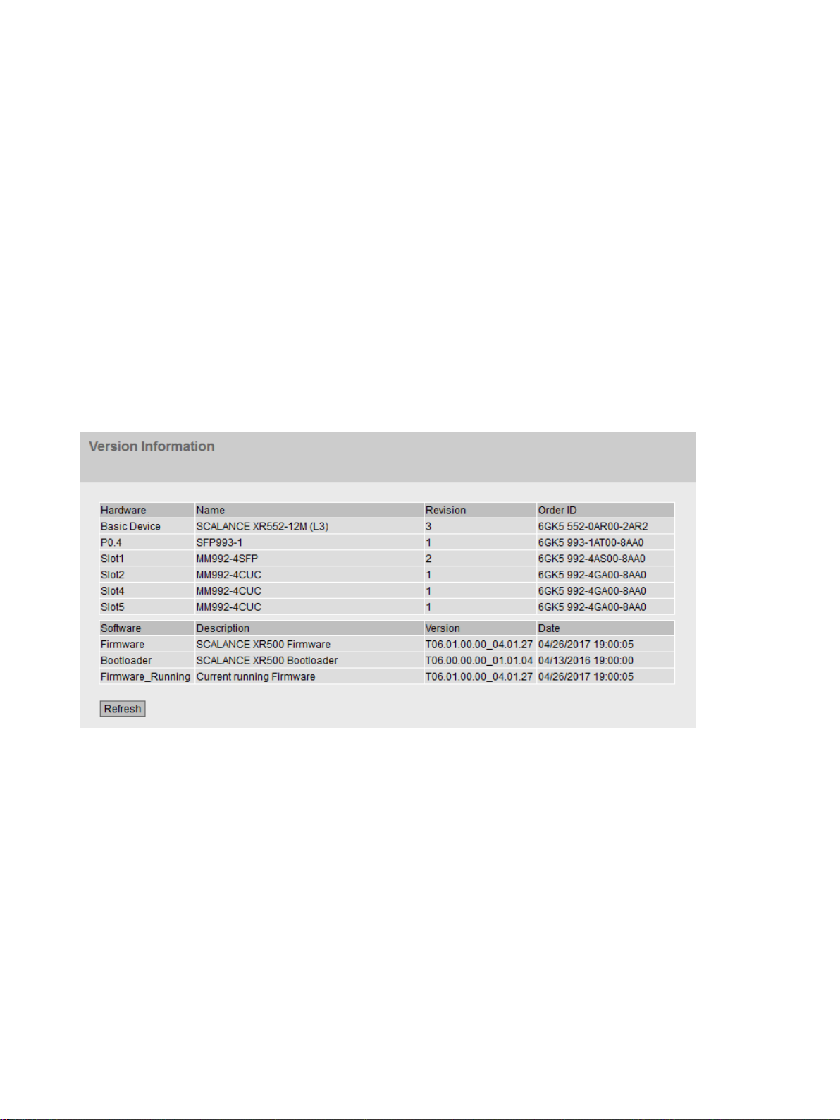
Messages
If you have enabled the "Automatic Save" mode and you change a parameter the the following
message appears in the display area "Changes will be saved automatically in x seconds. Press
'Write Startup Config' to save the changes immediately. Saving starts only after the timer in
the message has elapsed. In this case the following message "Saving configuration data in
progress. Please do not switch off the device". How long saving takes depends on the device.
Do not switch off the device immediately after the timer has elapsed.
5.3.2 Versions
Versions of hardware and software
This page shows the versions of the hardware and software of the device. You cannot configure
anything on this page.
Configuring with Web Based Management
5.3 The "Information" menu
Description of the displayed values
Table 1 has the following columns:
● Hardware
– Basic Device
Shows the basic device.
– PX.X
X.X = port in which the SFP module is inserted.
– SlotX
"X" = slot number: Module plugged into this slot.
● Name
Shows the name of the device or module.
SCALANCE XM-400/XR-500 Web Based Management (WBM)
Configuration Manual, 05/2017, C79000-G8976-C248-12 83

Configuring with Web Based Management
5.3 The "Information" menu
● Revision
Shows the hardware version of the device.
● Article number
Shows the article number of the device or described module.
Table 2 has the following columns:
● Software
– Firmware
Shows the current firmware version. If a new firmware file was downloaded and the
device has not yet restarted, the firmware version of the downloaded firmware file is
displayed here. After the next restart, the downloaded firmware is activated and used.
– Bootloader
Shows the version of the boot software stored on the device.
● Description
Shows the short description of the software.
● Version
Shows the version number of the software version.
● Date
Shows the date on which the software version was created.
5.3.3 Identification & Maintenance
Identification and Maintenance data
This page contains information about device-specific vendor and maintenance data such as
the order number, serial number, version number etc. You cannot configure anything on this
page.
SCALANCE XM-400/XR-500 Web Based Management (WBM)
84 Configuration Manual, 05/2017, C79000-G8976-C248-12

Description of the displayed values
The table has the following rows:
● Manufacturer ID
Shows the manufacturer ID.
● Order ID
Shows the order number.
● Serial Number
Shows the serial number.
● Hardware Revision
Shows the hardware version.
● Software version
Shows the software version.
● Revision Counter
Regardless of a version change, this box always displays the value "0".
● Revision Date
Date and time of the last revision
Configuring with Web Based Management
5.3 The "Information" menu
● Function tag
Shows the function tag (plant designation) of the device. The plant designation (HID) is
created during configuration of the device with HW Config of STEP 7.
● Location tag
Shows the location tag of the device. The location identifier (LID) is created during
configuration of the device with HW Config of STEP 7.
● Date
Shows the date created during configuration of the device with HW Config of STEP 7.
● Descriptor
Shows the description created during configuration of the device with HW Config of STEP 7.
SCALANCE XM-400/XR-500 Web Based Management (WBM)
Configuration Manual, 05/2017, C79000-G8976-C248-12 85

Configuring with Web Based Management
5.3 The "Information" menu
5.3.4 ARP / Neighbors
5.3.4.1 ARP Table
Assignment of MAC address and IPv4 address
With the Address Resolution Protocol (ARP), there is a unique assignment of MAC address
to IPv4 address. This assignment is kept by each network node in its own separate ARP table.
The WBM page shows the ARP table of the device.
Description of the displayed values
The table has the following columns:
● Interface
Shows the interface via which the row entry was learnt.
● MAC Address
Shows the MAC address of the destination or source device.
● IP Address
Shows the IP address of the destination device.
● Media Type
Shows the type of connection.
– Dynamic
The device recognized the address data automatically.
– Static
The addresses were entered as static addresses.
SCALANCE XM-400/XR-500 Web Based Management (WBM)
86 Configuration Manual, 05/2017, C79000-G8976-C248-12
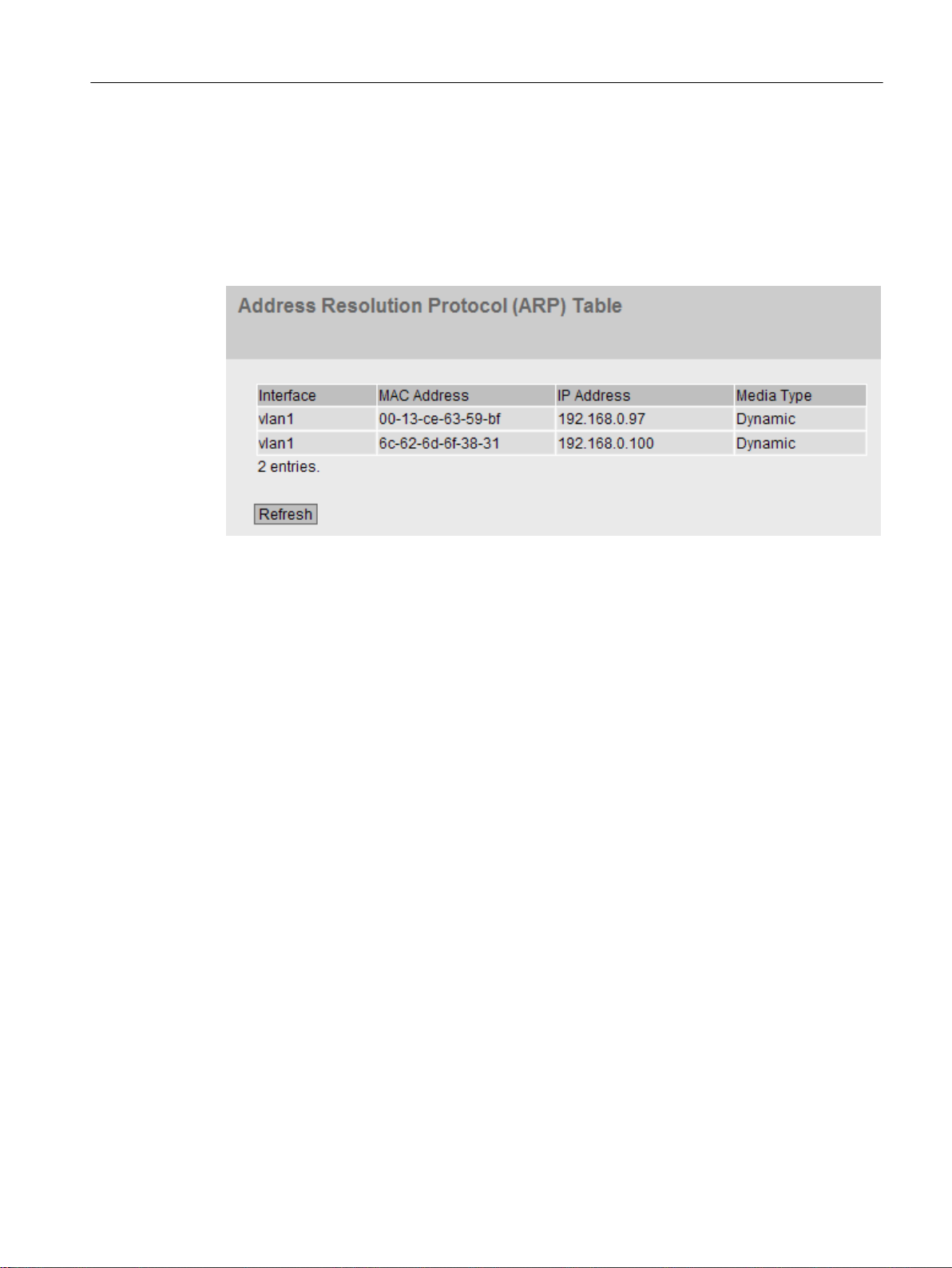
5.3.4.2 IPv6 Neighbor Table
Assignment of MAC address and IPv6 address
Via the IPv6 neighbor table, there is a unique assignment of MAC address to IPv6 address.
This assignment is kept by each network node in its own separate neighbor table.
Configuring with Web Based Management
5.3 The "Information" menu
Description of the displayed values
The table has the following columns:
● Interface
Displays the interface via which the row entry was learnt.
● MAC Address
Shows the MAC address of the destination or source device.
● IP Address
Shows the IPv6 address of the destination device.
● Media Type
Shows the type of connection.
– Dynamic
The device recognized the address data automatically.
– Static
The addresses were entered as static addresses.
5.3.5 Log Table
Logging events
The device allows you to log occurring events, some of which you can specify on the page of
the "System > Events" menu. This, for example, allows you to record when an authentication
attempt failed or when the connection status of a port has changed.
SCALANCE XM-400/XR-500 Web Based Management (WBM)
Configuration Manual, 05/2017, C79000-G8976-C248-12 87
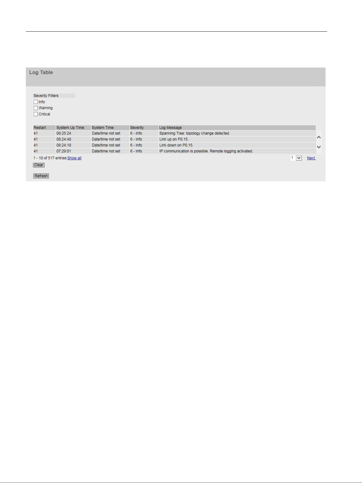
Configuring with Web Based Management
5.3 The "Information" menu
The content of the events log table is retained even when the device is turned off.
Description of the displayed values
Severity Filters
You can filter the entries in the table according to severity. Select the required entries in the
check boxes above the table.
● Info
When this parameter is enabled, all entries of the category "Info" are displayed.
● Warning
When this parameter is enabled, all entries of the category "Warning" are displayed.
● Critical
When this parameter is enabled, all entries of the category "Critical" are displayed.
To display all entries, select either all of them or leave the check boxes empty.
The table has the following columns:
● Restart
Counts the number of restarts since you last reset to factory settings and shows the device
restart after which the corresponding event occurred.
● System Up Time
Shows the time the device has been running since the last restart when the described event
occurred.
● System Time
If the system time is set, the date and time are also displayed at which the event occurred.
● Severity
Sorts the entry into the categories above.
● Log Message
Displays a brief description of the event that has occurred.
SCALANCE XM-400/XR-500 Web Based Management (WBM)
88 Configuration Manual, 05/2017, C79000-G8976-C248-12

Description of the buttons and input boxes
"Clear" button
Click this button to delete the content of the event log file. All entries are deleted regardless of
what you have selected under "Severity Filters".
The display is also cleared. The restart counter is only reset after you have restored the device
to the factory settings and restarted the device.
Note
The number of entries in this table is restricted to 1200. The table can contain 400 entries for
each severity. When this number is reached, the oldest entries of the relevant severity are
discarded. The table remains permanently in memory.
"Show all" button
Click this button to display all the entries on the WBM page. Note that displaying all messages
can take some time.
"Next" button
Configuring with Web Based Management
5.3 The "Information" menu
Click this button to go to the next page.
"Prev" button
Click this button to go to the previous page.
Drop-down list for page change
From the drop-down list, select the page you want to go to.
"Update" button
Refreshes the display of the values in the table.
5.3.6 Faults
Error status
if an error occurs, it is shown on this page. On the device, errors are indicated by red fault LED
lighting up.
Internal errors of the device and errors that you configure on the following pages are indicated:
● System > Events"
● "System" > Fault Monitoring"
Errors of the "Cold/Warm Start" event can be deleted by a confirmation.
The calculation of the time of an error always begins after the last system start.
If there are no errors present, the fault LED switches off.
SCALANCE XM-400/XR-500 Web Based Management (WBM)
Configuration Manual, 05/2017, C79000-G8976-C248-12 89

Configuring with Web Based Management
5.3 The "Information" menu
Description of the displayed values
● No. of Signaled Faults
Number of errors displayed since the last startup.
● Reset Counters
Click "Reset Counters" to reset all counters. The counter is reset when there is a restart.
The table contains the following columns:
● Fault Time
Shows the time the device has been running since the last system restart when the
described error/fault occurred.
● Fault Description
Displays a brief description of the fault/error that has occurred.
● Clear Fault State
If the "Clear Fault State" button is enabled, you can delete the fault.
SCALANCE XM-400/XR-500 Web Based Management (WBM)
90 Configuration Manual, 05/2017, C79000-G8976-C248-12

5.3.7 Redundancy
5.3.7.1 Spanning Tree
Introduction
The page shows the current information about the Spanning Tree and the settings of the root
bridge.
Configuring with Web Based Management
5.3 The "Information" menu
Description of the displayed values
The following fields are displayed:
● Spanning Tree Mode
Shows the set mode. You specify the mode in "Layer 2 > Configuration" and in "Layer 2 >
MSTP > General".
The following values are possible:
– '-'
– STP
– RSTP
– MSTP
● Instance ID
Shows the number of the instance. The parameter depends on the configured mode.
SCALANCE XM-400/XR-500 Web Based Management (WBM)
Configuration Manual, 05/2017, C79000-G8976-C248-12 91

Configuring with Web Based Management
5.3 The "Information" menu
● Bridge Priority / Root Priority
Which device becomes the root bridge is decided by the bridge priority. The bridge with the
highest priority (in other words, with the lowest value for this parameter) becomes the root
bridge. If several devices in a network have the same priority, the device whose MAC
address has the lowest numeric value will become the root bridge. Both parameters, bridge
priority and MAC address together form the bridge identifier. Since the root bridge manages
all path changes, it should be located as centrally as possible due to the delay of the frames.
The value for the bridge priority is a whole multiple of 4096 with a range of values from 0
to 32768.
● Bridge Address / Root Address
The bridge address shows the MAC address of the device and the root address shows the
MAC address of the root switch.
● Root Cost
Shows the path costs from the device to the root bridge.
● Bridge Status
Shows the status of the bridge, e.g. whether or not the device is the root bridge.
● Regional root priority (available only with MSTP)
For a description, see Bridge priority / Root priority
● Regional root address (available only with MSTP)
Shows the MAC address of the device.
● Regional Root Cost (available only with MSTP)
Shows the path costs from the regional root bridge to the root bridge.
The table has the following columns:
● Port
Shows the port via which the device communicates. The port is made up of the module
number and the port number, for example port 0.1 is module 0, port 1.
● Role
Shows the status of the port. The following values are possible:
– Disabled
The port was removed manually from the Spanning Tree and will no longer be taken
into account by the Spanning Tree.
– Designated
The ports leading away from the root bridge.
– Alternate
The port with an alternative route to a network segment
– Backup
If a switch has several ports to the same network segment, the "poorer" Port becomes
the backup port.
– Root
The port that provides the best route to the root bridge.
– Master
This port points to a root bridge located outside the MST region.
SCALANCE XM-400/XR-500 Web Based Management (WBM)
92 Configuration Manual, 05/2017, C79000-G8976-C248-12

Configuring with Web Based Management
5.3 The "Information" menu
● Status
Displays the current status of the port. The values are only displayed. The parameter
depends on the configured protocol. The following statuses are possible:
– Discarding
The port receives BPDU frames. Other incoming or outgoing frames are discarded.
– Listening
The port receives and sends BPDU frames. The port is involved in the spanning tree
algorithm. Other outgoing and incoming frames are discarded.
– Learning
The port actively learns the topology; in other words, the node addresses. Other
outgoing and incoming frames are discarded.
– Forwarding
Following the reconfiguration time, the port is active in the network. The port receives
and sends data frames.
● Oper. Version
Describes the type of spanning tree in which the port operates
● Priority
If the path calculated by the spanning tree is possible over several ports of a device, the
port with the highest priority (in other words the lowest value for this parameter) is selected.
A value between 0 and 240 can be entered for the priority in steps of 16. If you enter a
value that cannot be divided by 16, the value is automatically adapted. The default is 128.
● Path Cost
This parameter is used to calculate the path that will be selected. The path with the lowest
value is selected. If several ports of a device have the same value, the port with the lowest
port number will be selected.
If the value in the "Cost Calc." box is "0", the automatically calculated value is shown.
Otherwise, the value of the "Cost Calc." is displayed.
The calculation of the path costs is largely based on the transmission speed. The higher
the achievable transmission speed is, the lower the value of the path costs.
Typical values for path costs with rapid spanning tree:
– 10,000 Mbps = 2,000
– 1000 Mbps = 20,000
– 100 Mbps = 200,000
– 10 Mbps = 2,000,000.
SCALANCE XM-400/XR-500 Web Based Management (WBM)
Configuration Manual, 05/2017, C79000-G8976-C248-12 93
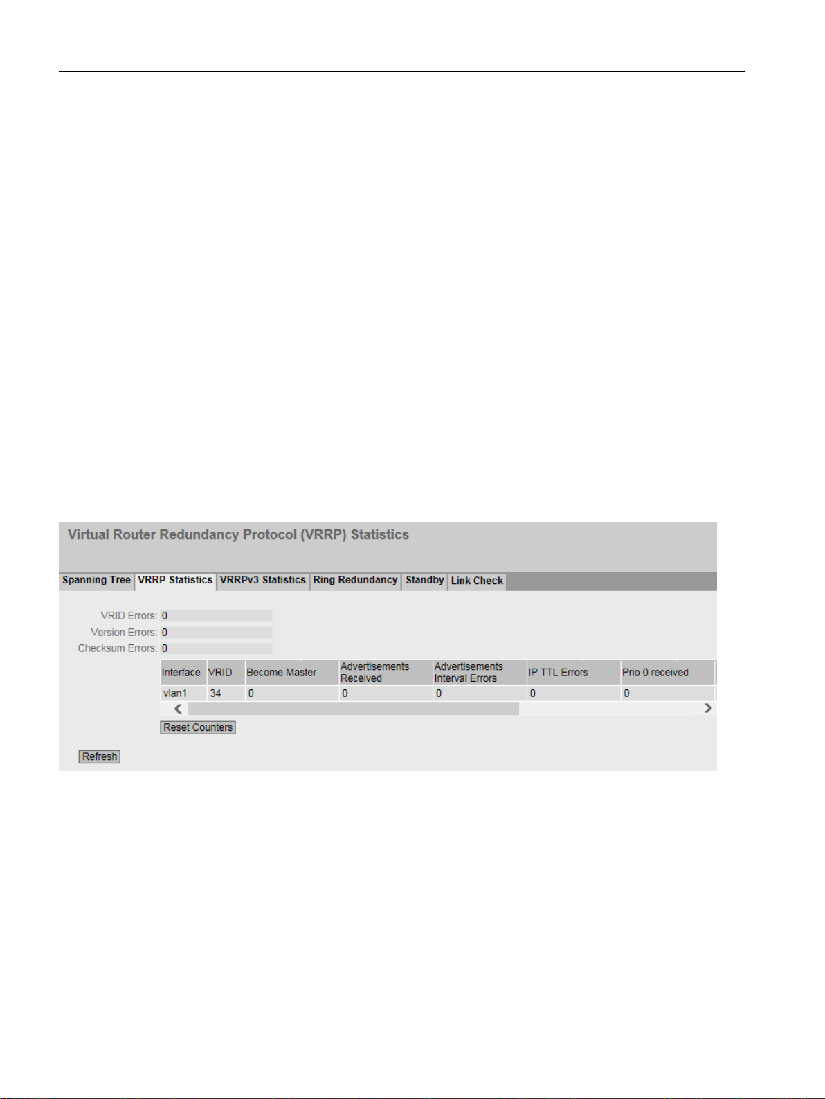
Configuring with Web Based Management
5.3 The "Information" menu
● Edge Type
Shows the type of the connection. The following values are possible:
– Edge Port
There is an end device at this port.
– No Edge Port
There is a Spanning Tree or Rapid Spanning Tree device at this port.
● P.t.P. Type
Shows the type of point-to-point link. The following values are possible:
– P.t.P.
With half duplex, a point-to-point link is assumed.
–
Shared Media
With a full duplex connection, a point-to-point link is not assumed.
5.3.7.2 VRRP statistics
Introduction
This page shows the statistics of the VRRP protocol and all configured virtual routers.
Description of the displayed values
The following fields are displayed:
● VRID Errors
Shows how many VRRP packets containing an unsupported VRID were received.
● Version Errors
Shows how many VRRP packets containing an invalid version number were received.
● Checksum Errors
Shows how many VRRP packets containing an invalid checksum were received.
SCALANCE XM-400/XR-500 Web Based Management (WBM)
94 Configuration Manual, 05/2017, C79000-G8976-C248-12

Configuring with Web Based Management
5.3 The "Information" menu
The table has the following columns:
● Interface
Interface to which the settings relate.
● VRID
Shows the ID of the virtual router.
Valid values are 1 to 255.
● Become Master
Shows how often this virtual router changed to the "Master" status.
● Advertisements Received
Shows how often a VRRP packet was received that contained a bad address list.
● Advertisement Interval Errors
Shows how many bad VRRP packets were received whose interval does not match the
value set locally.
● IP TTL Errors
Shows how many bad VRRP packets were received whose TTL (Time to live) value in the
IP header is incorrect.
● Prio 0 received
Shows how many VRRP packets with priority 0 were received. VRRP packets with priority
0 are sent when a master router is shut down. These packets allow a fast handover to the
relevant backup router.
● Prio 0 sent
Shows how many VRRP packets with priority 0 were sent. Packets with priority 0 are sent
when a master router is shut down. These packets allow a fast handover to the relevant
backup router.
● Invalid Type
Shows how many bad VRRP packets were received whose authentication type was not
type 0. Type 0 means "no authentication".
● Address List Errors
Shows how many bad VRRP packets were received whose address list does not match
the locally configured list.
SCALANCE XM-400/XR-500 Web Based Management (WBM)
Configuration Manual, 05/2017, C79000-G8976-C248-12 95

Configuring with Web Based Management
5.3 The "Information" menu
● Invalid Auth. Type
Shows how many bad VRRP packets were received whose authentication type does not
match.
● Auth. Type Mismatch
Shows that different authentication types are set.
● Packet Length Errors
Shows how many bad VRRP packets were received whose length is not correct.
5.3.7.3 VRRP Statistics
Introduction
This page shows the statistics of the VRRPv3 protocol and all configured virtual routers.
Description of the displayed values
The following fields are displayed:
● VRID Errors
Shows how many VRRPv3 packets containing an unsupported VRID were received.
● Version Errors
Shows how many VRRPv3 packets containing an invalid version number were received.
● Checksum Errors
Shows how many VRRPv3 packets containing an invalid checksum were received.
The table has the following columns:
● Interfaces
Interface to which the settings relate.
● VRID
Shows the ID of the virtual router. Valid values are 1 ... 255.
● Type
Shows the version of the IP protocol.
SCALANCE XM-400/XR-500 Web Based Management (WBM)
96 Configuration Manual, 05/2017, C79000-G8976-C248-12

Configuring with Web Based Management
5.3 The "Information" menu
● Become Master
Shows how often this virtual router changed to the "Master" status.
● Advertisements Received
Shows how many VRRPv3 packets were received.
● Advertisement Interval Errors
Shows how many bad VRRPv3 packets were received whose interval does not match the
value set locally.
● IP TTL Errors
Shows how many bad VRRPv3 packets were received whose TTL (Time to live) value in
the IP header is incorrect.
● Prio 0 received
Shows how many VRRPv3 packets with priority 0 were received. VRRPv3 packets with
priority 0 are sent when a master router is shut down. These packets allow a fast handover
to the relevant backup router.
● Prio 0 sent
Shows how many VRRPv3 packets with priority 0 were sent. Packets with priority 0 are
sent when a master router is shut down. These packets allow a fast handover to the relevant
backup router.
● Invalid Type
Shows how many bad VRRPv3 packets were received whose value in the "Type" field of
the IP header is invalid.
● Address List Errors
Shows how many bad VRRPv3 packets were received whose address list does not match
the locally configured list.
● Packet Length Errors
Shows how many bad VRRPv3 packets were received whose length is not correct.
SCALANCE XM-400/XR-500 Web Based Management (WBM)
Configuration Manual, 05/2017, C79000-G8976-C248-12 97
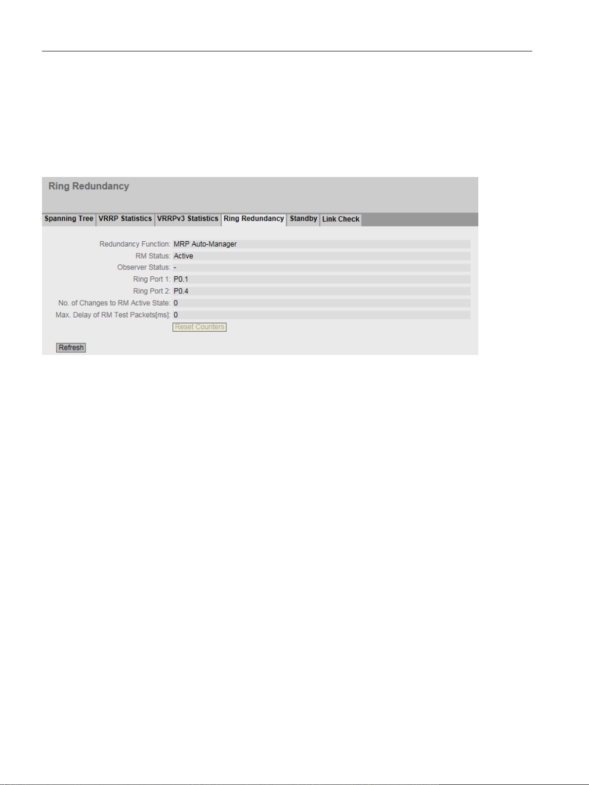
Configuring with Web Based Management
5.3 The "Information" menu
5.3.7.4 Ring redundancy
Information on ring redundancy
On this page, you obtain information about the status of the device in terms of ring redundancy.
The text boxes on this page are read-only.
SCALANCE XM-400/XR-500 Web Based Management (WBM)
98 Configuration Manual, 05/2017, C79000-G8976-C248-12

Description of the displayed values
The table has the following columns:
● Redundancy Function
The "Redundancy Function" column shows the role of the device within the ring:
– No Ring Redundancy (off)
The IE switch works without redundancy function.
– HRP Client
The IE switch operates as an HRP client.
– HRP Manager
The IE switch operates as an HRP manager.
– MRP Client
The IE switch operates as an MRP client.
– MRP Manager
The IE switch operates as an MRP manager. Using STEP 7, the role "Manager" was
set for the device.
– MRP Auto-Manager
The IE switch is operating as an MRP manager. Using WBM or CLI the role "MRP AutoManager" or using STEP 7 the role "Manager (Auto)" was set.
Configuring with Web Based Management
5.3 The "Information" menu
● RM Status
The "RM Status" column shows whether or not the IE switch is operating as redundancy
manager and whether it has opened or closed the ring in this role.
– Passive:
The IE switch is operating as redundancy manager and has opened the ring; in other
words, the line of switches connected to the ring ports is operating problem free. The
passive status is also displayed if the IE switch is not operating as the redundancy
manager (RM function disabled).
– Active:
The IE switch is operating as redundancy manager and has closed the ring; in other
words, the line of switches connected to the ring ports is interrupted (problem). The
redundancy manager connects its ring ports through and restores an uninterrupted
linear topology.
– If media redundancy in ring topologies is completely disabled, ring ports configured last
are displayed and the text "Ring Redundancy disabled" is displayed.
● Observer Status
Shows the current status of the observer.
● Ring Port 1 and Ring Port 2
The "Ring Port 1"and "Ring Port 2" columns show the ports being used as ring ports.
● No. of Changes to RM Active State
Shows how often the device as redundancy manager switched to the active status, i.e.
closed the ring.
If the redundancy function is disabled or the device is an "HRP/MRP client" , the text
"Redundancy Manager Disabled" appears.
SCALANCE XM-400/XR-500 Web Based Management (WBM)
Configuration Manual, 05/2017, C79000-G8976-C248-12 99

Configuring with Web Based Management
5.3 The "Information" menu
● Max. Delay of the RM Test Packets [ms]
Shows the maximum delay time of the test frames of the redundancy manager.
If the redundancy function is disabled or the device is an "HRP/MRP client" , the text
"Redundancy Manager Disabled" appears.
● Click the "Reset Counters" button to reset the counters on this page.
5.3.7.5 Standby
Information on standby redundancy
On this page, you obtain information about the status of the device in terms of standby
redundancy. The text boxes on this page are read-only.
Note
Device with the higher MAC address becomes master
When linking HRP rings redundantly, two devices are always configured as a master/slave
pair. This also applies to interrupted HRP rings = linear buses. When operating normally, the
device with the higher MAC address adopts the role of master.
This type of assignment is important in particular when a device is replaced. Depending on
the MAC addresses, the previous device with the slave function can take over the role of the
standby master.
The Standby tab shows the status of the standby function:
Description of the displayed values
The table has the following columns:
● Standby Ports
Shows the standby port.
● Standby Name
Standby Connection Name
SCALANCE XM-400/XR-500 Web Based Management (WBM)
100 Configuration Manual, 05/2017, C79000-G8976-C248-12
 Loading...