

Siemens SIMATIC NET, SCALANCE XC100-4OBR Operating Instructions Manual
SCALANCE XC100-4OBR
___________________
___________________
___________________
___________________
___________________
___________________
___________________
___________________
SIMATIC NET
Network components
SCALANCE XC100-4OBR
Operating Instructions
10/2013
C79000
Introduction
1
Safety notes
2
Description of the device
3
Mounting
4
Connection
5
Technical data
6
Dimension drawings
7
Approvals
8
-G8976-C297-02
Siemens AG
Industry Sector
Postfach 48 48
90026 NÜRNBERG
GERMANY
Order number: C79000-G8976-C297
Ⓟ
Copyright © Siemens AG 2012 - 2013.
All rights reserved
Warning notice system
DANGER
indicates that death or severe personal injury will result if proper precautions are not taken.
WARNING
indicates that death or severe personal injury may result if proper precautions are not taken.
CAUTION
indicates that minor personal injury can result if proper precautions are not taken.
NOTICE
indicates that property damage can result if proper precautions are not taken.
Qualified Personnel
personnel qualified
Proper use of Siemens products
WARNING
Siemens products may only be used for the applications described in the catalog and in the relevant technical
maintenance are required to ensure that the products operate safely and without any problems. The permissible
ambient conditions must be complied with. The information in the relevant documentation must be observed.
Trademarks
Disclaimer of Liability
Legal information
This manual contains notices you have to observe in order to ensure your personal safety, as well as to prevent
damage to property. The notices referring to your personal safety are highlighted in the manual by a safety alert
symbol, notices referring only to property damage have no safety alert symbol. These notices shown below are
graded according to the degree of danger.
If more than one degree of danger is present, the warning notice representing the highest degree of danger will
be used. A notice warning of injury to persons with a safety alert symbol may also include a warning relating to
property damage.
The product/system described in this documentation may be operated only by
task in accordance with the relevant documentation, in particular its warning notices and safety instructions.
Qualified personnel are those who, based on their training and experience, are capable of identifying risks and
avoiding potential hazards when working with these products/systems.
for the specific
Note the following:
documentation. If products and components from other manufacturers are used, these must be recommended
or approved by Siemens. Proper transport, storage, installation, assembly, commissioning, operation and
All names identified by ® are registered trademarks of Siemens AG. The remaining trademarks in this publication
may be trademarks whose use by third parties for their own purposes could violate the rights of the owner.
We have reviewed the contents of this publication to ensure consistency with the hardware and software
described. Since variance cannot be precluded entirely, we cannot guarantee full consistency. However, the
information in this publication is reviewed regularly and any necessary corrections are included in subsequent
editions.
10/2013 Technical data subject to change

Table of contents
1 Introduction ............................................................................................................................................. 5
2 Safety notes .......................................................................................................................................... 11
3 Description of the device ....................................................................................................................... 13
4 Mounting ............................................................................................................................................... 31
5 Connection ........................................................................................................................................... 37
6 Technical data ...................................................................................................................................... 43
7 Dimension drawings .............................................................................................................................. 45
8 Approvals .............................................................................................................................................. 49
1.1 On the Operating Instructions ........................................................................................................ 5
1.2 On the product ............................................................................................................................... 8
3.1 View ............................................................................................................................................. 13
3.2 Purpose ........................................................................................................................................ 14
3.3 Installation guidelines ................................................................................................................... 17
3.4 Areas of application ..................................................................................................................... 18
3.5 Installation guide .......................................................................................................................... 20
3.6 "SET" button ................................................................................................................................. 25
3.7 LED displays ................................................................................................................................ 28
3.7.1 "Bypass" LED ............................................................................................................................... 28
3.7.2 "DM" LED ..................................................................................................................................... 28
3.7.3 LEDs "S1" and "S2" ..................................................................................................................... 29
3.7.4 LEDs "L1" and "L2" ...................................................................................................................... 30
4.1 Safety notices for installation ....................................................................................................... 31
4.2 Types of installation ..................................................................................................................... 32
4.3 Mounting on DIN rails .................................................................................................................. 33
4.4 Installation on a standard S7-300 rail .......................................................................................... 35
4.5 Installation on a standard S7-1500 rail ........................................................................................ 36
5.1 Safety when connecting up .......................................................................................................... 37
5.2 Spring-loaded terminal ................................................................................................................. 38
5.3 Power supply ................................................................................................................................ 39
5.4 Signaling contact .......................................................................................................................... 40
5.5 Digital input .................................................................................................................................. 41
5.6 Optical connectors ....................................................................................................................... 42
SCALANCE XC100-4OBR
Operating Instructions, 10/2013, C79000-G8976-C297-02
3

Table of contents
Index .................................................................................................................................................... 53
SCALANCE XC100-4OBR
4 Operating Instructions, 10/2013, C79000-G8976-C297-02

1
1.1
On the Operating Instructions
Purpose of the Operating Instructions
Validity of the Operating Instructions
Designations used
Classification
Description
Terms used
the designation of the product line is used.
device.
brackets.
Note
The term "bypass relay" is used in these Operating Instructions as a generic term for the
various device names.
Further documentation
These operating instructions support you when installing and connecting up devices of the
SCALANCE XC-100 product line.
These Operating Instructions apply to all devices of the SCALANCE XC-100 product line.
Unless mentioned otherwise, the descriptions in these operating instructions refer to all
devices of the SCALANCE XC-100 product line.
Product line For all devices and variants in the product line,
Device The device name is used to identify a specific
Variant For a variant of the device, the device name
The "SIMATIC NET Industrial Ethernet Network Manual" contains information on other
SIMATIC NET products that you can operate along with the devices of this product line in an
Industrial Ethernet network.
There, you will find among other things optical performance data of the communications
partner that you require for the installation.
has the appropriate variant added to it in
SCALANCE XC-100
SCALANCE XC100-4OBR
e.g. SCALANCE XC100-4OBR
(single mode)
The "SIMATIC NET Industrial Ethernet Network Manual" can be found on the Internet pages
of Siemens Industry Online Support under the following entry ID:
27069465 (http://support.automation.siemens.com/WW/view/en/27069465
SCALANCE XC100-4OBR
Operating Instructions, 10/2013, C79000-G8976-C297-02
)
5

Introduction
SIMATIC NET manuals
SIMATIC NET glossary
1.1 On the Operating Instructions
You will find SIMATIC NET manuals on the Internet pages of Siemens Industry Online
Support:
● using the search function:
Link to Siemens Industry Online Support
(
http://support.automation.siemens.com/WW/llisapi.dll?func=cslib.csinfo2&aktprim=99&la
ng=en)
Enter the entry ID of the relevant manual as the search item.
● In the navigation panel on the left hand side in the area "Industrial Communication":
Link to the area "Industrial Communication"
(
http://support.automation.siemens.com/WW/llisapi.dll?func=cslib.csinfo&lang=de&siteid=
csius&aktprim=0&extranet=standard&viewreg=WW&objid=10805878&treeLang=en)
Go to the required product group and make the following settings:
tab "Entry list", Entry type "Manuals"
You will find the documentation for the SIMATIC NET products relevant here on the data
medium that ships with some products:
● Product CD / product DVD
● SIMATIC NET Manual Collection
Explanations of the specialist terms used in this documentation can be found in the SIMATIC
NET glossary.
You will find the SIMATIC NET glossary here:
● SIMATIC NET Manual Collection
The DVD ships with certain SIMATIC NET products.
● On the Internet under the following entry ID:
50305045 (http://support.automation.siemens.com/WW/view/en/50305045
)
SCALANCE XC100-4OBR
6 Operating Instructions, 10/2013, C79000-G8976-C297-02

Introduction
Security messages
Note
For its automation and drives product portfolio, Siemens provides IT security mechanisms to
support secure ope
developed also taking into account the aspect of IT security. We therefore recommend that
you regularly check for updates of our products and that you only use the latest versions.
Yo
Here, you can register for a product
For the secure operation of a plant/machine,
components in a full IT security concept for the entire plant/machine that represents the state
of the art in IT technology. You will find information on this in:
(
en
Products from other manufacturers that are being used must also
1.1 On the Operating Instructions
ration of the plant/machine. Our products are continuously being further
u will find information in:
Industrial Security (http://www.siemens.com/industrialsecurity)
-specific newsletter.
it is also necessary to integrate the automation
Siemens Industry online support
http://support.automation.siemens.com/WW/llisapi.dll?func=cslib.csinfo2&aktprim=99&lang=
)
be taken into account.
SCALANCE XC100-4OBR
Operating Instructions, 10/2013, C79000-G8976-C297-02
7

Introduction
1.2
On the product
Catalogs
Order numbers
Variant
Order number
Description
6GK5100-4AV00-2FA2
with TAP function *
6GK5100-4AV00-2DA2
without TAP function *
(multimode)
Components of the product
1.2 On the product
You will find the order numbers for the Siemens products of relevance here in the following
catalogs:
● SIMATIC NET Industrial Communication / Industrial Identification, catalog IK PI
● SIMATIC Products for Totally Integrated Automation and Micro Automation, catalog
ST 70
● Industry Mall - catalog and ordering system for automation and drive technology, Online
catalog
https://eb.automation.siemens.com/goos/WelcomePage.aspx?regionUrl=/en&language=
(
en)
You can request the catalogs and additional information from your Siemens representative.
The variants of the SCALANCE XC100-4OBR have the following order numbers:
SCALANCE XC100-4OBR
(single mode)
SCALANCE XC100-4OBR
* You will find an explanation of the TAP function in the section "Purpose (Page 14)".
The following parts ship with a SCALANCE XC100-4OBR:
● A device with the following factory settings:
– Monitoring voltage: 24 V (-20 %)
– Startup time: 30 s
● Operating Instructions (compact)
● A 4-pin terminal block for the power supply (spring-loaded terminal)
● A 2-pin terminal block for the signaling contact (spring-loaded terminal)
● A 2-pin terminal block for the digital input (spring-loaded terminal)
6GK5100-4AW00-2FA2 with TAP function *
SCALANCE XC100-4OBR
8 Operating Instructions, 10/2013, C79000-G8976-C297-02
● Securing screw for mounting on an S7 standard rail

Introduction
Accessories
Network cable for connecting the SCALANCE XC100-4OBR to end devices
Component
Length
Order number
MM FO connecting cable SC/SC
1 m
6XV1843-5EH10-0CC0
MM FO connecting cable SC/BFOC
1 m
6XV1843-5EH10-0CB0
MM FO connecting cable SC/LC
1 m
6XV1843-5EH10-0CA0
SM FC connecting cable SC/SC
1 m
6XV1843-5FH10-0CC0
SM FO connecting cable SC/BFOC
1 m
6XV1843-5FH10-0CB0
SM FO connecting cable SC/LC
1 m
6XV1843-5FH10-0CA0
Network cable for connecting the SCALANCE XC100-4OBR to the network
Component
Attenuation factor per length
at 1300 nm
Order number
MM FO robust cable GP
1 dB/km
6XV1873-2R
MM FO standard cable GP
0.7 dB/km
6XV1873-2A
MM FO ground cable
0.7 dB/km
6XV1873-2G
SM FO robust cable GP
0.5 dB/km
6XV1843-2R
SFP transceiver
Component
optical budget
Order number
SFP991-1
13 dB
6GK5 991-1AD00-8AA0
SFP991-1LD
19 dB
6GK5 991-1AF00-8AA0
SFP991-1LH+
29 dB
6GK5 991-1AE00-8AA0
SFP992-1LD
12 dB
6GK5 992-1AM00-8AA0
SFP992-1LH
17 dB
6GK5 992-1AN00-8AA0
Note
The designations LD, LH and LH+ are used for optical single mode interfaces with
SCALANCE X. IE switches with the corresponding interfaces have the same designation,
e.g. SCALANCE X204
1.2 On the product
The following table shows several SFP transceivers with their optical budgets. You require
the optical budget to calculate the cable length (see section "Installation guide (Page 20)").
-2LD.
SCALANCE XC100-4OBR
Operating Instructions, 10/2013, C79000-G8976-C297-02
9
Introduction
Unpacking and checking
WARNING
Do not use any parts that show evidence of damage
1.2 On the product
If you use damaged parts, there is no guarantee that the device will function according to
the specification.
If you use damaged parts, this can lead to the following problems:
• Injury to persons
• Loss of the approvals
• Violation of the EMC regulations
• Damage to the device and other components
Use only undamaged parts.
1. Make sure that the package is complete.
2. Check all the parts for transport damage.
SCALANCE XC100-4OBR
10 Operating Instructions, 10/2013, C79000-G8976-C297-02

2
Read the safety notices
Safety notices on use in hazardous areas
General safety notices relating to protection against explosion
WARNING
EXPLOSION HAZARD
Safety notices when using the device according to Hazardous Locations (HazLoc)
Note the following safety notices. These relate to the entire working life of the device.
You should also read the safety notices relating to handling in the individual sections,
particularly in the sections "Installation" and "Connecting up".
DO NOT OPEN WHEN ENERGIZED.
If you use the device under HazLoc conditions you must also keep to the following safety
notices in addition to the general safety notices for protection against explosion:
This equipment is suitable for use in Class I, Division 2, Groups A, B, C and D or nonhazardous locations only.
This equipment is suitable for use in Class I, Zone 2, Group IIC or non-hazardous locations
only.
SCALANCE XC100-4OBR
Operating Instructions, 10/2013, C79000-G8976-C297-02
11

Safety notes
SCALANCE XC100-4OBR
12 Operating Instructions, 10/2013, C79000-G8976-C297-02
3
3.1
View
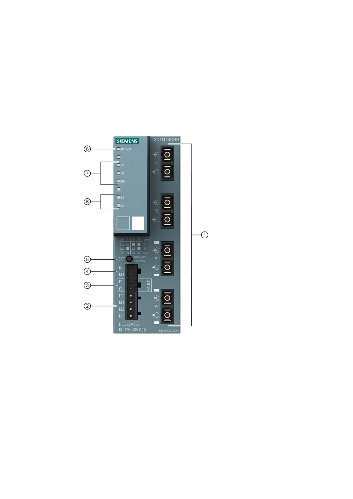
①
Optical connectors
②
Connector for redundant power supply L1/M1/M2/L2
③
Connector for signaling contact F1/F2
④
Connector for digital input IN/M3
⑤
"SET" button
⑥
LEDs "L1" and "L2" for indicating the power supply
⑦
LEDs "S1", "S2" and "DM" for displaying the mode and configuration
⑧
"BYPASS" LED for indicating the operating mode
The following figure shows the individual components of the SCALANCE XC100-4OBR.
SCALANCE XC100-4OBR
Operating Instructions, 10/2013, C79000-G8976-C297-02
13
Description of the device
3.2
Purpose
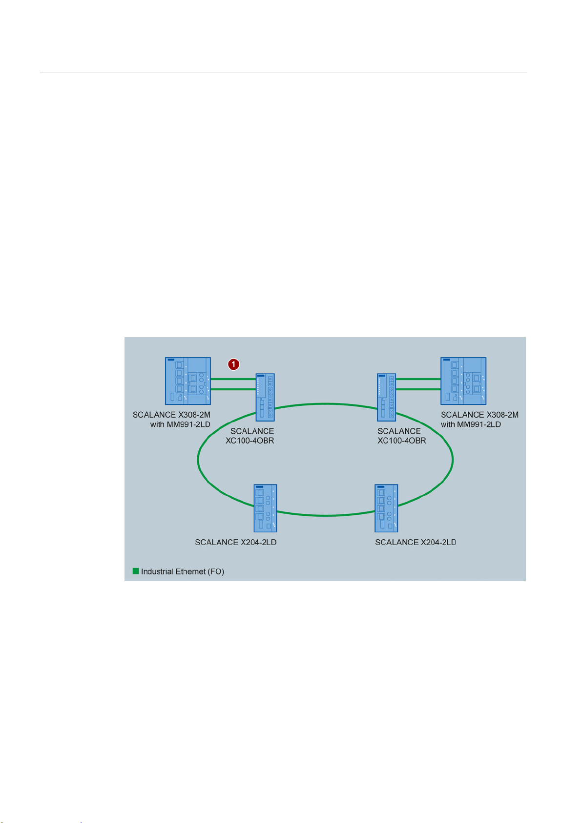
Basic function
Normal operation
3.2 Purpose
With the optical bypass relay SCALANCE XC100-4OBR, you can activate and deactivate
end devices in bus, star and ring structures without interrupting the communication between
other network components.
If an error occurs, the bypass relay bypasses the connected end device so that the
connection in the network is retained.
An end device is a device connected to the network via a bypass relay.
When the SCALANCE XC100-4OBR is supplied with power, the network interfaces are
connected to the end device interfaces of the bypass relay
bypass relay is connected is therefore in the network.
①. The end device to which the
SCALANCE XC100-4OBR
14 Operating Instructions, 10/2013, C79000-G8976-C297-02
Description of the device
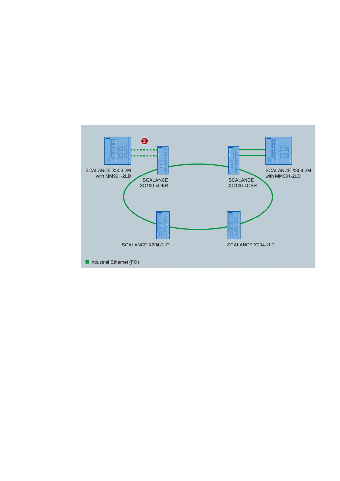
Bypass mode
3.2 Purpose
If the voltage of the end device drops, for example due to a fault or during maintenance, the
voltage of the SCALANCE XC100-4OBR also drops. The monitoring voltage is no longer in
the set range.
The bypass relay then interconnects its two network interfaces within 10 ms. As result, the
connection to the end device that has been turned off is inactive and the bypass relay forms
the connection to the neighboring network components or bypass relays
②.
When you turn on the voltage of the end device and therefore of the SCALANCE XC1004OBR again, the two network interfaces remain connected until the end device is
operational. It is only after this startup time that the bypass relay connects the network
interfaces to the end device interfaces again.
SCALANCE XC100-4OBR
Operating Instructions, 10/2013, C79000-G8976-C297-02
15

Description of the device
TAP function
Bypass relay with TAP function
Bypass relay without TAP function
Note
The insertion loss is lower with a bypass relay without TAP functi
3.2 Purpose
In bypass mode, a SCALANCE XC100-4OBR with TAP function forwards the received data
not only to the neighboring network components. The TAP function has the effect that the
data is also sent to the end device. The end device receives and sends data as if it were
connected to the network. The data that the end device sends in bypass mode is not
forwarded to the network by the bypass relay.
With a bypass relay with TAP function, the end device can establish a link to the neighboring
network components in bypass mode.
If you use a bypass relay with TAP function in MRP or HRP rings, you can activate and
deactivate the connected end device without the redundancy manager initiating
reconfiguration routines in the ring.
If you use a bypass relay without TAP function in MRP and HRP rings, the redundancy
manager reacts when the connected end device is turned on or off again. The redundancy
manager enables the alternative (redundant) ring section and initiates the reconfiguration of
the logical communications connections.
on.
SCALANCE XC100-4OBR
16 Operating Instructions, 10/2013, C79000-G8976-C297-02

Description of the device
3.3
Installation guidelines
Operating the SCALANCE XC100-4OBR in an (R)STP network
Bypassing an (R)STP bridge
Note
If you connect the (R)STP bridge with the (R)STP network via other ports, the TAP function
causes a network loop in bypass mode and communication in the network f
Bypassing the root bridge
Operating the SCALANCE XC100-4OBR in a redundant ring structure
Bypassing the redundancy manager
Note
If the redundancy manager is bypassed, this causes a network loop and the communication
fails.
Bypassing ring nodes
3.3 Installation guidelines
Note the information on the topic of redundancy in the configuration manuals of the
connected devices.
You will find the configuration manuals of the SCALANCE X switches on the Internet pages
of Siemens Industry Online Support
http://support.automation.siemens.com/WW/llisapi.dll?func=cslib.csinfo2&aktprim=99&lang=
(
en).
If you want to bypass an (R)STP bridge with a SCALANCE XC100-4OBR using the TAP
function, connect the (R)STP bridge to the (R)STP network only via the two ports of the
bypass relay.
If the root bridge of an (R)STP network is bypassed by a bypass relay, an alternative root
bridge is selected. By turning the root bridge on and off, the (R)STP network is recalculated.
If an (R)STP bridge is bypassed, the (R)STP section is longer and attenuation increases.
This changes the path costs.
Within an MRP or HRP ring, a permanently configured redundancy manager must not be
bypassed using a bypass relay.
ails.
If the ring nodes are operated in the redundancy modes "MRP Auto Manager" or "Automatic
Redundancy Detection", any ring nodes can be connected and disconnected by the bypass
relay.
If the current redundancy manager is bypassed, another ring node takes over control of the
redundancy. If the redundancy manager changes, the logical communications connections
are reconfigured.
SCALANCE XC100-4OBR
Operating Instructions, 10/2013, C79000-G8976-C297-02
17
 Loading...