

Siemens SCALANCE XC-100 Operating Instructions Manual
SCALANCE XC-100
___________________
___________________
___________________
___________________
___________________
___________________
___________________
___________________
___________________
SIMATIC NET
Industrial Ethernet switches
SCALANCE XC-100
Operating Instructions
06/2016
C79000
Introduction
1
Safety notices
2
Description of the device
3
Mounting
4
Connecting up
5
Maintenance and
troubleshooting
6
Technical specifications
7
Certifications and approvals
8
Dimension drawings
9
-G8976-C415-02
Siemens AG
Division Process Industries and Drives
Postfach 48 48
90026 NÜRNBERG
GERMANY
C79000-G8976-C415-02
Ⓟ
Copyright © Siemens AG 2016.
All rights reserved
Legal information
Warning notice system
DANGER
indicates that death or severe personal injury will result if proper precautions are not taken.
WARNING
indicates that death or severe personal injury may result if proper precautions are not taken.
CAUTION
indicates that minor personal injury can result if proper precautions are not taken.
NOTICE
indicates that property damage can result if proper precautions are not taken.
Qualified Personnel
personnel qualified
Proper use of Siemens products
WARNING
Siemens products may only be used for the applications described in the catalog and in the relevant technical
maintenance are required to ensure that the products operate safely and without any problems. The permissible
ambient conditions must be complied with. The information in the relevant documentation must be observed.
Trademarks
Disclaimer of Liability
This manual contains notices you have to observe in order to ensure your personal safety, as well as to prevent
damage to property. The notices referring to your personal safety are highlighted in the manual by a safety alert
symbol, notices referring only to property damage have no safety alert symbol. These notices shown below are
graded according to the degree of danger.
If more than one degree of danger is present, the warning notice representing the highest degree of danger will
be used. A notice warning of injury to persons with a safety alert symbol may also include a warning relating to
property damage.
The product/system described in this documentation may be operated only by
task in accordance with the relevant documentation, in particular its warning notices and safety instructions.
Qualified personnel are those who, based on their training and experience, are capable of identifying risks and
avoiding potential hazards when working with these products/systems.
Note the following:
documentation. If products and components from other manufacturers are used, these must be recommended
or approved by Siemens. Proper transport, storage, installation, assembly, commissioning, operation and
All names identified by ® are registered trademarks of Siemens AG. The remaining trademarks in this publication
may be trademarks whose use by third parties for their own purposes could violate the rights of the owner.
We have reviewed the contents of this publication to ensure consistency with the hardware and software
described. Since variance cannot be precluded entirely, we cannot guarantee full consistency. However, the
information in this publication is reviewed regularly and any necessary corrections are included in subsequent
editions.
for the specific
06/2016 Subject to change

Table of contents
1 Introduction ............................................................................................................................................. 5
2 Safety notices ......................................................................................................................................... 9
3 Description of the device ....................................................................................................................... 11
4 Mounting ............................................................................................................................................... 19
5 Connecting up ....................................................................................................................................... 29
6 Maintenance and troubleshooting .......................................................................................................... 37
7 Technical specifications ........................................................................................................................ 39
3.1 Product overview .................................................................................................................... 11
3.2 Device views ........................................................................................................................... 12
3.2.1 Device view of a SCALANCE XC106-2 .................................................................................. 12
3.2.2 Device view of a SCALANCE XC108 ..................................................................................... 13
3.2.3 Device view of a SCALANCE XC116 ..................................................................................... 14
3.2.4 Device view of a SCALANCE XC124 ..................................................................................... 15
3.3 LED display ............................................................................................................................. 16
3.4 SET button .............................................................................................................................. 17
4.1 Safety notices for installation .................................................................................................. 19
4.2 Types of installation ................................................................................................................ 21
4.3 Mounting on DIN rails ............................................................................................................. 22
4.4 Installation on a standard S7-300 rail ..................................................................................... 23
4.5 Installation on a standard S7-1500 rail ................................................................................... 25
4.6 Wall mounting ......................................................................................................................... 27
4.7 Changing the position of the securing bar .............................................................................. 28
5.1 Safety when connecting up ..................................................................................................... 29
5.2 Wiring rules ............................................................................................................................. 31
5.3 Power supply .......................................................................................................................... 32
5.4 Signaling contact ..................................................................................................................... 34
5.5 Functional ground ................................................................................................................... 36
7.1 Technical specifications SCALANCE XC106-2 ...................................................................... 39
7.2 Technical specifications of the SCALANCE XC108 ............................................................... 41
7.3 Technical specifications of the SCALANCE XC116 ............................................................... 43
7.4 Technical specifications of the SCALANCE XC124 ............................................................... 45
7.5 Mechanical stability (in operation) .......................................................................................... 46
SCALANCE XC-100
Operating Instructions, 06/2016, C79000-G8976-C415-02
3

Table of contents
8 Certifications and approvals .................................................................................................................. 47
9 Dimension drawings .............................................................................................................................. 55
Index .................................................................................................................................................... 59
8.1 EU declaration of conformity .................................................................................................. 52
8.1.1 ATEX ...................................................................................................................................... 53
8.1.2 EMC ....................................................................................................................................... 53
8.1.3 RoHS ...................................................................................................................................... 54
8.1.4 Products ................................................................................................................................. 54
9.1 SCALANCE XC-100 dimension drawings ............................................................................. 55
SCALANCE XC-100
4 Operating Instructions, 06/2016, C79000-G8976-C415-02

1
Purpose of the Operating Instructions
Validity of the Operating Instructions
Designations used
Classification
Description
Terms used
term SCALANCE X-100 is used.
term SCALANCE XC-100 is used.
Device
If information relates to a specific device, the device name is used.
e.g. SCALANCE XC106-2
Further documentation
These operating instructions support you when installing and connecting up devices of the
SCALANCE XC-100 product group.
These operating instructions apply to the following devices:
● SCALANCE XC106-2
● SCALANCE XC108
● SCALANCE XC116
● SCALANCE XC124
Unless mentioned otherwise, the descriptions in these operating instructions refer to all
devices of the SCALANCE XC-100 product group named above in the section on validity.
Product line The product line includes all devices and variants of all product groups.
If information applies to all product groups within the product line, the
Product group If information applies to all devices and variants of a product group, the
In the system manuals "Industrial Ethernet / PROFINET Industrial Ethernet" and "Industrial
Ethernet / PROFINET passive network components", you will find information on other
SIMATIC NET products that you can operate along with the devices of this product line in an
Industrial Ethernet network.
There, you will find among other things optical performance data of the communications
partner that you require for the installation.
SCALANCE X-100
SCALANCE XC-100
SCALANCE XC-100
Operating Instructions, 06/2016, C79000-G8976-C415-02
5

Introduction
SIMATIC NET manuals
SIMATIC NET glossary
Catalogs
You will find the system manuals here:
● On the data medium that ships with some products:
– Product CD / product DVD
– SIMATIC NET Manual Collection
● On the Internet pages of Siemens Industry Online Support under the following entry IDs:
– 27069465 (http://support.automation.siemens.com/WW/view/en/27069465
– 84922825 (http://support.automation.siemens.com/WW/view/en/84922825)
You will find the SIMATIC NET manuals here:
● On the data medium that ships with some products:
– Product CD / product DVD
– SIMATIC NET Manual Collection
● On the Internet pages of Siemens Industry Online Support
(https://support.industry.siemens.com/cs/ww/en/ps/15247
Explanations of many of the specialist terms used in this documentation can be found in the
SIMATIC NET glossary.
You will find the SIMATIC NET glossary on the Internet at the following address:
50305045 (http://support.automation.siemens.com/WW/view/en/50305045
)
Industrial Ethernet / PROFINET Industrial Ethernet System Manual
Industrial Ethernet / PROFINET - Passive network components System Manual
).
)
You will find the order numbers for the Siemens products of relevance here in the following
catalogs:
● SIMATIC NET Industrial Communication / Industrial Identification, catalog IK PI
● SIMATIC Products for Totally Integrated Automation and Micro Automation, catalog
ST 70
● Industry Mall - catalog and ordering system for automation and drive technology, Online
catalog
https://eb.automation.siemens.com/goos/WelcomePage.aspx?regionUrl=/en&language=
(
en)
You can request the catalogs and additional information from your Siemens representative.
SCALANCE XC-100
6 Operating Instructions, 06/2016, C79000-G8976-C415-02
Introduction
Security information
Trademarks
Unpacking and checking
WARNING
Do not use any parts that show evidence of damage
Recycling and disposal
Siemens provides products and solutions with industrial security functions that support the
secure operation of plants, solutions, machines, equipment and/or networks. They are
important components in a holistic industrial security concept. With this in mind, Siemens’
products and solutions undergo continuous development. Siemens recommends strongly
that you regularly check for product updates.
For the secure operation of Siemens products and solutions, it is necessary to take suitable
preventive action (e.g. cell protection concept) and integrate each component into a holistic,
state-of-the-art industrial security concept. Third-party products that may be in use should
also be considered. You will find more information about Industrial Security in:
Industrial security (http://www.siemens.com/industrialsecurity
)
To stay informed about product updates as they occur, sign up for a product-specific
newsletter. You will find more information about this in
Product support (https://support.industry.siemens.com/cs/ww/en/ps/15247/pm
)
The following and possibly other names not identified by the registered trademark sign ® are
registered trademarks of Siemens AG:
SIMATIC NET, SCALANCE, C-PLUG, OLM
If you use damaged parts, there is no guarantee that the device will function according to
the specification.
If you use damaged parts, this can lead to the following problems:
• Injury to persons
• Loss of the approvals
• Violation of the EMC regulations
• Damage to the device and other components
Use only undamaged parts.
1. Make sure that the package is complete.
2. Check all the parts for transport damage.
SCALANCE XC-100
Operating Instructions, 06/2016, C79000-G8976-C415-02
The products are low in pollutants and can be recycled. For environmentally friendly
recycling and the disposal of your old device contact a certified disposal company for
electronic scrap.
7
Introduction
Electrostatic discharge
NOTICE
Electrostatic sensitive devices (ESD)
Electronic modules contain electrostatic sensitive components
These components can easily be destroyed if handled incorrectly.
Note the following instructions to avoid damage.
• Touch electronic modules only when you absolutely need to work on them.
• If electronic modules need to be touched, the body of the person involved must first be
electrostatically discharged and grounded.
• Do not bring electronic modules in contact with electrically isolating materials such as
plastic film, isolating table top pads or clothing made of synthetic fibers.
• Place the modules only on conductive surfaces.
• Pack, store and transport electronic modules and components only in conductive
packaging such as metalized plastic or metal containers, conductive foam or household
aluminum foil.
SCALANCE XC-100
8 Operating Instructions, 06/2016, C79000-G8976-C415-02
2
Read the safety notices
Safety notices on use in hazardous areas
General safety notices relating to protection against explosion
WARNING
EXPLOSION HAZARD
Safety notices when using the device according to Hazardous Locations (HazLoc)
Note the following safety notices. These relate to the entire working life of the device.
You should also read the safety notices relating to handling in the individual sections,
particularly in the sections "Installation" and "Connecting up".
Do not open the device when the supply voltage is turned on.
If you use the device under HazLoc conditions you must also keep to the following safety
notices in addition to the general safety notices for protection against explosion:
This equipment is suitable for use in Class I, Division 2, Groups A, B, C and D or nonhazardous locations only.
This equipment is suitable for use in Class I, Zone 2, Group IIC or non-hazardous locations
only.
SCALANCE XC-100
Operating Instructions, 06/2016, C79000-G8976-C415-02
9

Safety notices
SCALANCE XC-100
10 Operating Instructions, 06/2016, C79000-G8976-C415-02
3
3.1
Product overview
Article numbers
Device
Description
Article number
mode fiber-optic cable
SCALANCE XC108
8 x 10/100 Mbps RJ-45 ports
6GK5 108-0BA00-2AC2
SCALANCE XC124
24 x 10/100 Mbps RJ-45 ports
6GK5 124-0BA00-2AC2
Components of the product
Spare parts
Component
Description
Order number
pack of 5
pack of 5
SCALANCE XC106-2 6 x 10/100 Mbps RJ-45 ports, 2 x 10/100 Mbps SC ports, multi-
SCALANCE XC116 16 x 10/100 Mbps RJ-45 ports 6GK5 116-0BA00-2AC2
6GK5 106-2BB00-2AC2
The following components are supplied with a SCALANCE XC-100:
● One IE switch
● A 4-pin terminal block for the power supply (spring-loaded terminal)
● A 2-pin terminal block for the signaling contact (spring-loaded terminal)
The following spare parts are available for SCALANCE XC-100:
Spring-loaded terminal block, 4
terminals
4-terminal spring-loaded terminal block to connect the power supply (24 VDC),
for SCALANCE X/W/S/M,
6GK5 980-1DB10-0AA5
Spring-loaded terminal block, 2
terminals
SCALANCE XC-100
Operating Instructions, 06/2016, C79000-G8976-C415-02
2-terminal spring-loaded terminal block to connect the signaling contact (24 VDC),
for SCALANCE X/W/S/M,
6GK5 980-0BB10-0AA5
11
Description of the device
3.2
Device views
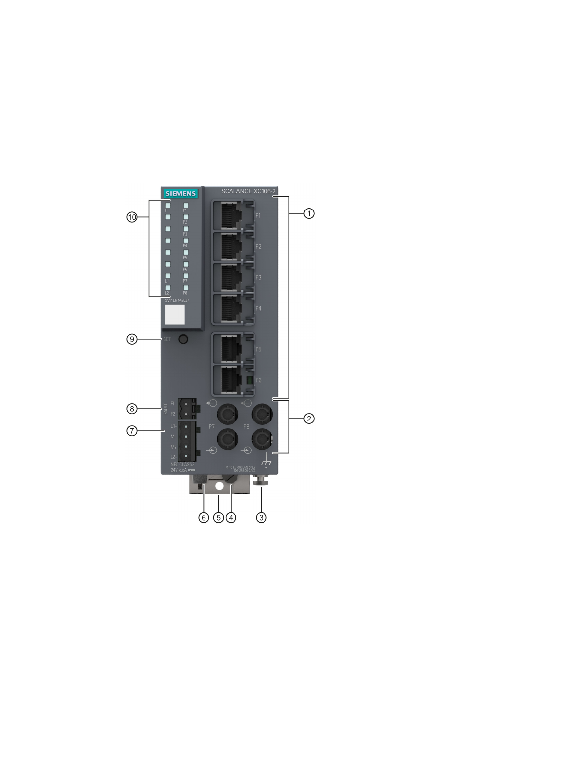
3.2.1
Device view of a SCALANCE XC106-2
①
Electrical ports
②
Optical ports
③
Grounding screw
④
Knurled screw
⑤
Securing bar
⑥
Levering aid for moving the securing bar with a screwdriver
⑦
Power supply
⑧
Signaling contact
⑨
"SET" button
⑩
LED display
3.2 Device views
The following figure shows an overview of the components of the SCALANCE XC106-2.
SCALANCE XC-100
12 Operating Instructions, 06/2016, C79000-G8976-C415-02
Description of the device
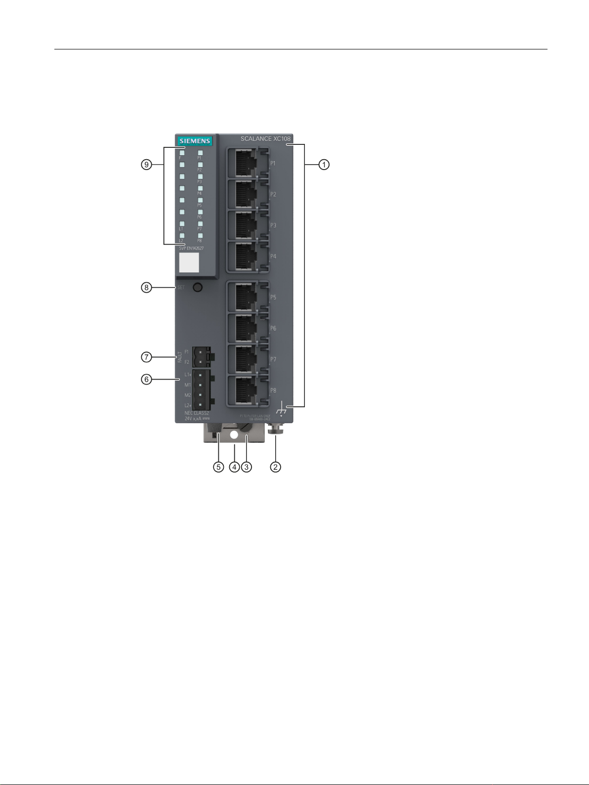
3.2.2
Device view of a SCALANCE XC108
①
Electrical ports
②
Grounding screw
③
Knurled screw
④
Securing bar
⑤
Levering aid for moving the securing bar with a screwdriver
⑥
Power supply
⑦
Signaling contact
⑧
"SET" button
⑨
LED display
3.2 Device views
The following figure shows an overview of the components of the SCALANCE XC108.
SCALANCE XC-100
Operating Instructions, 06/2016, C79000-G8976-C415-02
13
Description of the device
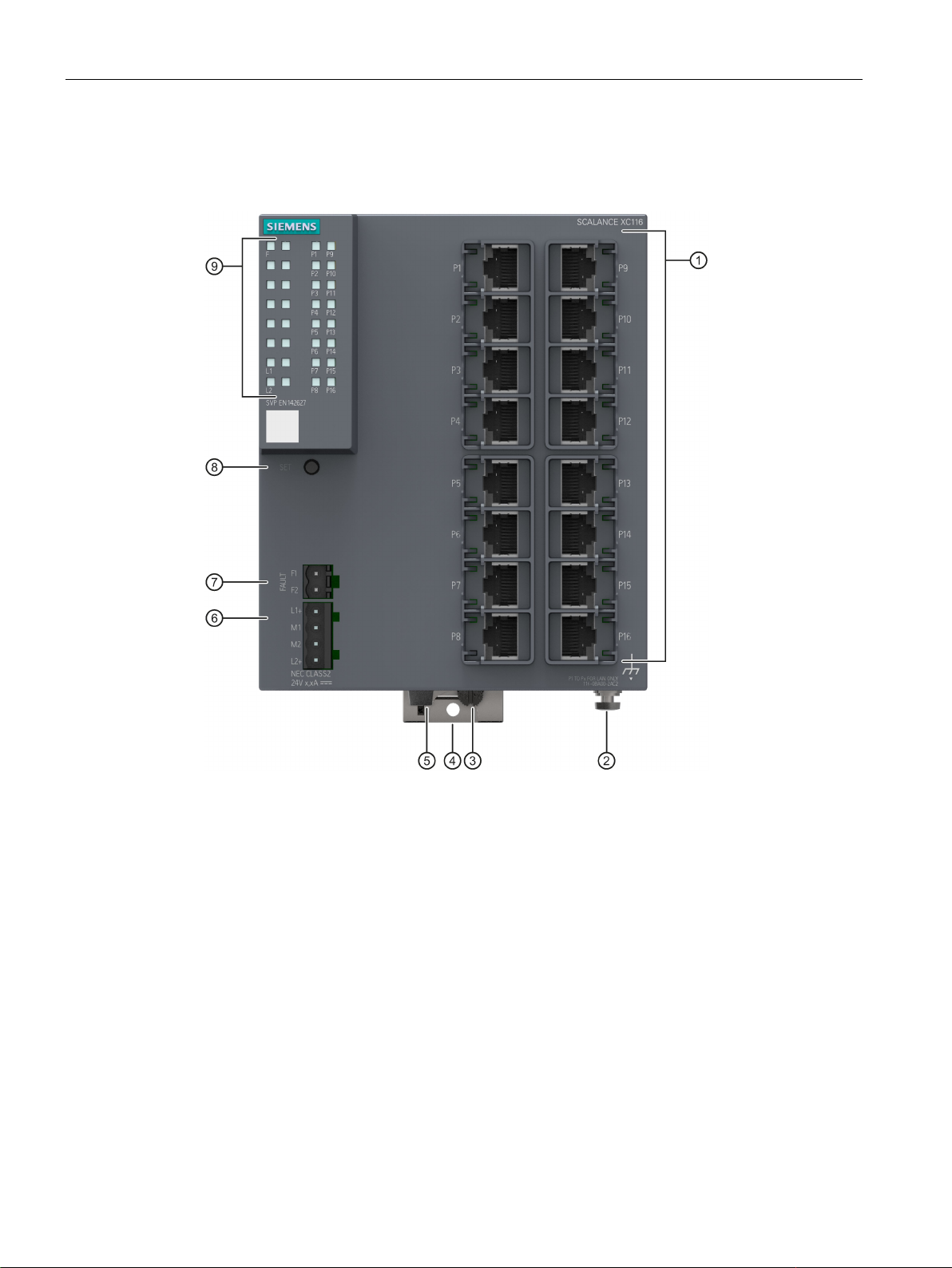
3.2.3
Device view of a SCALANCE XC116
①
Electrical ports
②
Grounding screw
③
Knurled screw
④
Securing bar
⑤
Levering aid for moving the securing bar with a screwdriver
⑥
Power supply
⑦
Signaling contact
⑧
"SET" button
⑨
LED display
3.2 Device views
The following figure shows an overview of the components of the SCALANCE XC106-2.
SCALANCE XC-100
14 Operating Instructions, 06/2016, C79000-G8976-C415-02
Description of the device
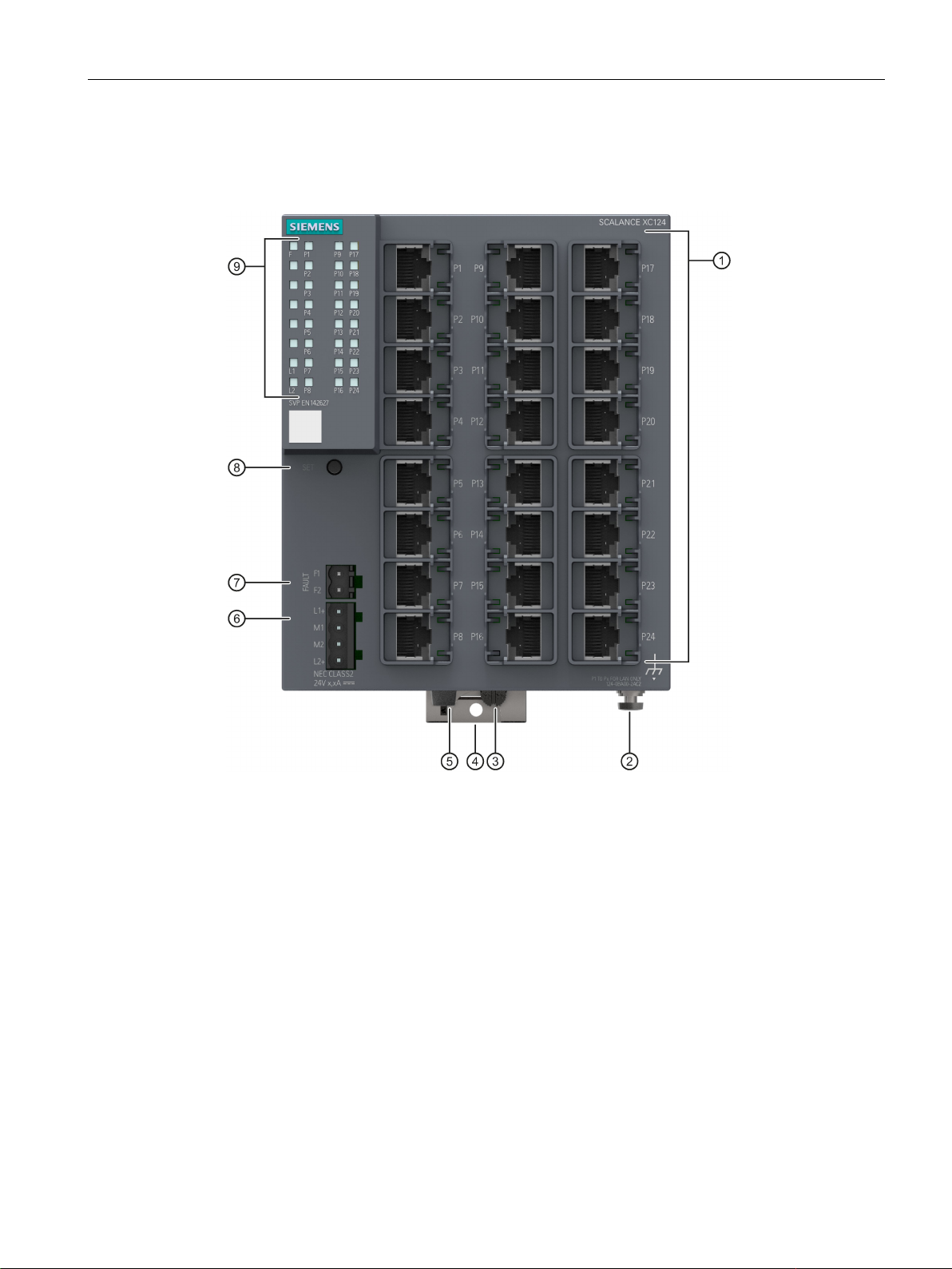
3.2.4
Device view of a SCALANCE XC124
①
Electrical ports
②
Grounding screw
③
Knurled screw
④
Securing bar
⑤
Levering aid for moving the securing bar with a screwdriver
⑥
Power supply
⑦
Signaling contact
⑧
"SET" button
⑨
LED display
3.2 Device views
The following figure shows an overview of the components of the SCALANCE XC106-2.
SCALANCE XC-100
Operating Instructions, 06/2016, C79000-G8976-C415-02
15

Description of the device
3.3
LED display
Fault LED "F" (red LED)
LED color
LED status
Meaning
-
Off
No error detected.
Power LEDs “L1” and “L2” (green LEDs)
L1/L2 LEDs
L1/L2 connector
LED color
LED status
Green
Lit
Power supply L1 or L2 is connected.
-
Off
Power supply L1 and L2 are not connected or L1 and L2 <9.6 V.
Note
If the green LED is not lit, no other signal LED lights up either.
Port LEDs "P" (green/yellow LEDs)
LED color
LED status
Meaning
Green
Lit
Link exists, no data reception at port
Yellow
Lit
Link exists, data reception at port
Yellow
Flashing
Setting or display of the fault mask
3.3 LED display
The fault LED indicates the incorrect functioning of the device.
Red Lit The IE switch detects an error. At the same time, the signaling contact opens.
The following faults/errors are detected:
1. Link down event on a monitored port.
2. Loss of the power supply of one of the two redundant power supplies or the power supply drops below 9.6 V.
3. Both power supplies are below approximately 9.6 V (voltage too low).
The power LEDs show the status of the power supply at connectors L1 and L2.
The port LEDs indicate the status of the ports.
SCALANCE XC-100
16 Operating Instructions, 06/2016, C79000-G8976-C415-02
Description of the device
3.4
SET button
Position
Function
Setting the fault mask
Factory setting
Changing the setting
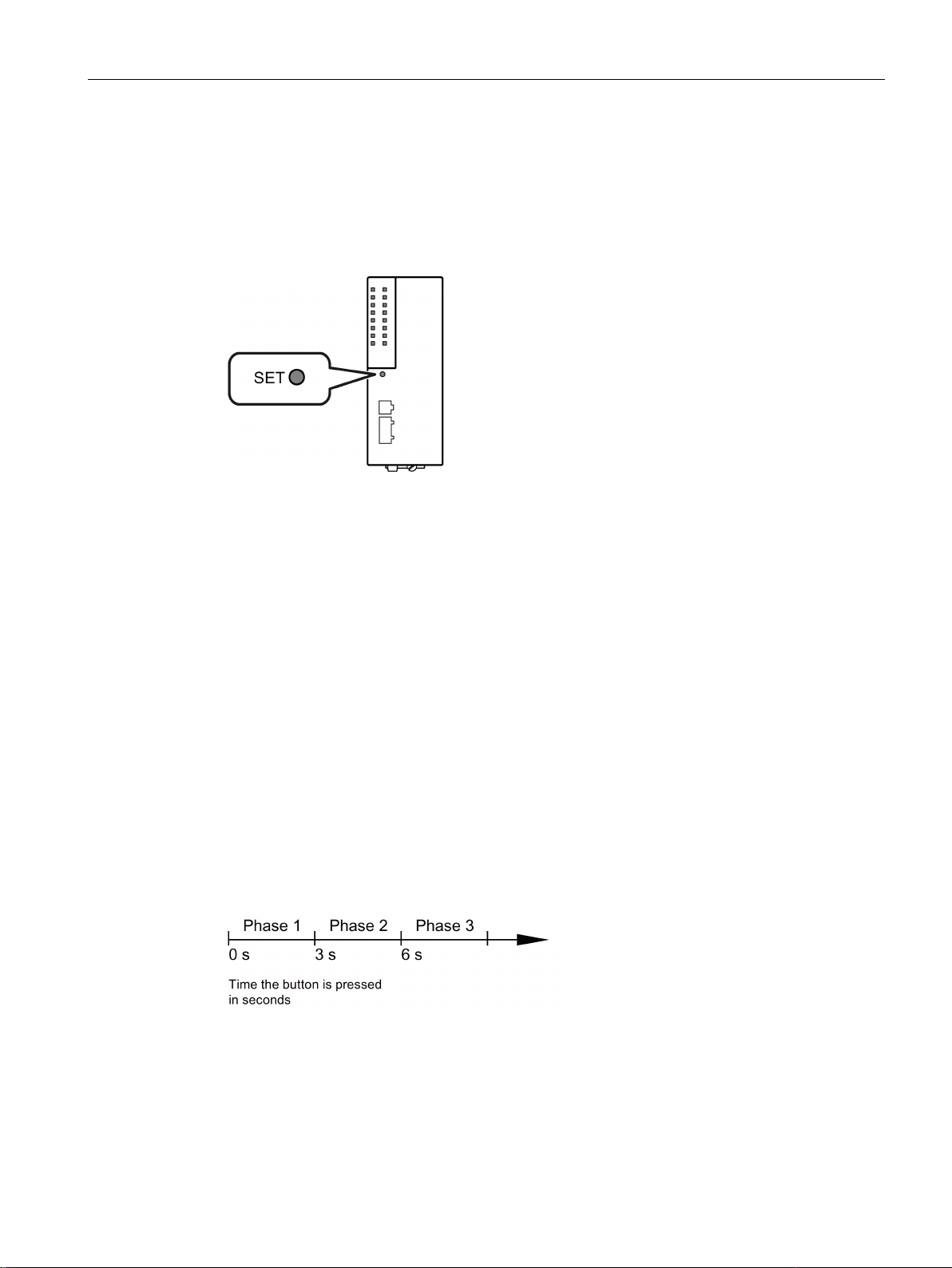
3.4 SET button
The "SET" button is located on the front of the SCALANCE XC-100.
Image 3-1 Position of the "SET" button
With the SET button, you can display and change the set fault mask.
When supplied (factory defaults), the fault mask is set so that the power supply L1+/M1 is
monitored. No ports are monitored.
If you connect a power supply to L2+/M2, adapt the fault mask accordingly: Clear the error
LED and the signaling contact or set the fault mask to the power supply L2+/M2.
The changed settings remain after cycling power to the device.
Different settings are made depending on how long you hold down the SET button, as
described in the following table:
SCALANCE XC-100
Operating Instructions, 06/2016, C79000-G8976-C415-02
17
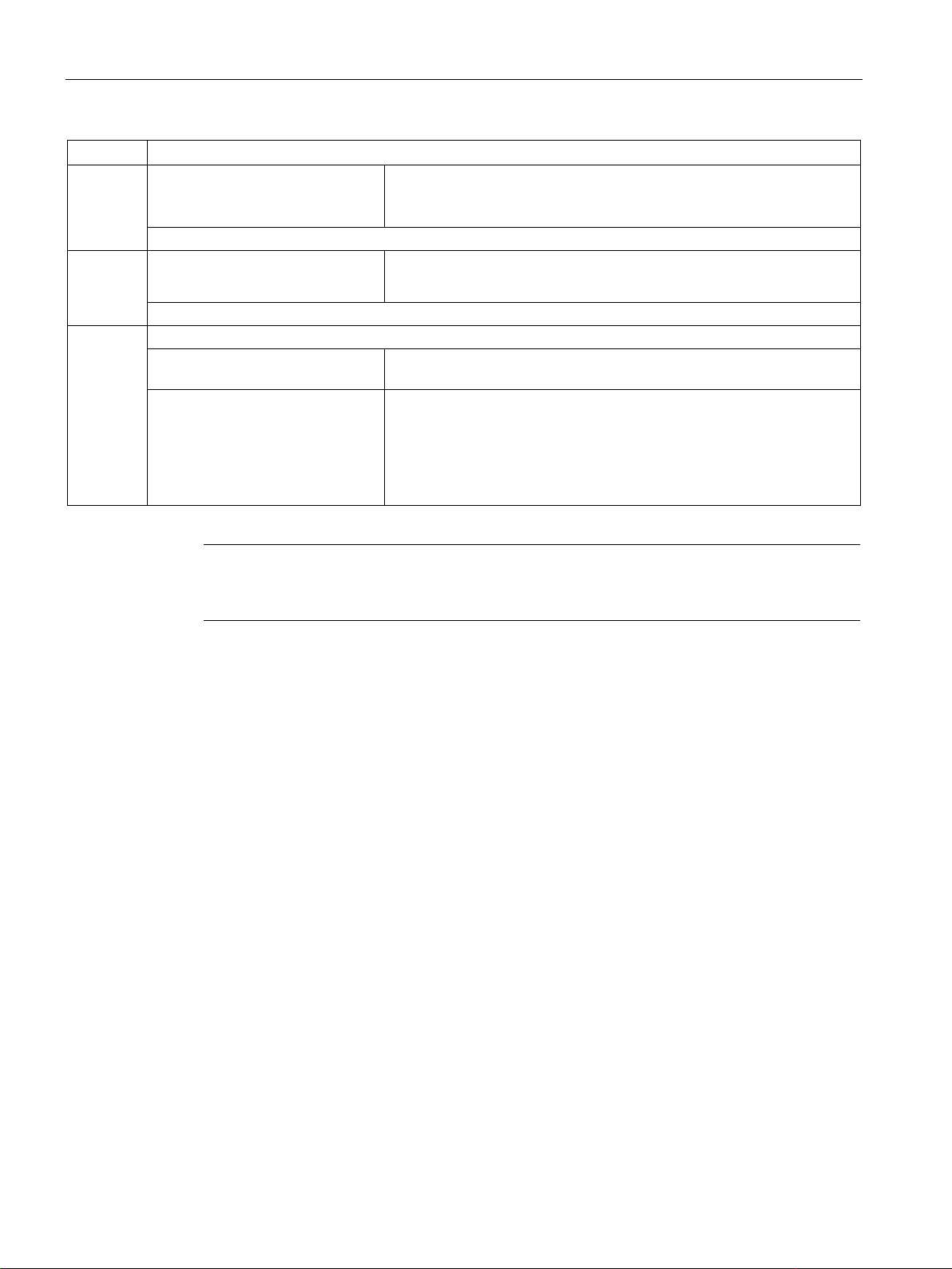
Description of the device
Phase
Description
If no fault mask is set, all port LEDs flash one after the other.
If you release the button in phase 2, this has no effect.
This new status is adopted and stored as the new fault mask in phase 3.
aborted.
Note
If an empty fault mask is set or needs to be set, the 2 port LEDs flash alternately. If the fault
mask is empty, no port is
Error/fault
3.4 SET button
1
2 LEDs flash at 2.5 Hz The current status is displayed.
3
LEDs flash at 5 Hz The currently set fault mask is displayed. The LEDs of the monitored
ports flash.
If you release the button in phase 1, this has no effect.
• The LEDs of the ports at which there is currently a link flash.
LEDs flashing If you release the SET button while the LEDs are still flashing, storing is
LEDs lit If you release the SET button as soon as the LEDs light up, the current
settings will be stored.
The stored status is displayed.
• The monitored ports are indicated by statically lit LEDs.
• The monitored power supply is indicated by statically lit LEDs.
monitored.
If the link is lost at a monitored port or a monitored power supply is lost, this is signaled as
follows:
● the red fault LED lights up
● the signaling contact is opened
SCALANCE XC-100
18 Operating Instructions, 06/2016, C79000-G8976-C415-02
 Loading...