

Siemens SCALANCE X414-3E, SCALANCE X408-2 Compact Operating Instructions

SCALANCE X-400
___________________
___________________
___________________
___________________
___________________
___________________
___________________
___________________
SIMATIC NET
Industrial Ethernet Switches
SCALANCE X-400
Compact Operating Instructions
10/2013
A5E01020054
-06
Introduction
1
Safety instructions
2
Description
3
Installation
4
Connecting up
5
Certifications and approvals
6
Technical specifications
7
Dimension drawings
8
Siemens AG
Industry Sector
Postfach 48 48
90026 NÜRNBERG
GERMANY
Order number: A5E01020054
Ⓟ
12/2013 Technical data subject to change
Copyright © Siemens AG 2009 - 2013.
All rights reserved
Legal information
Warning notice system
This manual contains notices you have to observe in order to ensure your personal safety, as well as to prevent
damage to property. The notices referring to your personal safety are highlighted in the manual by a safety alert
symbol, notices referring only to property damage have no safety alert symbol. These notices shown below are
graded according to the degree of danger.
DANGER
indicates that death or severe personal injury will result if proper precautions are not taken.
WARNING
indicates that death or severe personal injury may result if proper precautions are not taken.
CAUTION
indicates that minor personal injury can result if proper precautions are not taken.
NOTICE
indicates that property damage can result if proper precautions are not taken.
If more than one degree of danger is present, the warning notice representing the highest degree of danger will
be used. A notice warning of injury to persons with a safety alert symbol may also include a warning relating to
property damage.
Qualified Personnel
The product/system described in this documentation may be operated only by
personnel qualified
for the specific
task in accordance with the relevant documentation, in particular its warning notices and safety instructions.
Qualified personnel are those who, based on their training and experience, are capable of identifying risks and
avoiding potential hazards when working with these products/systems.
Proper use of Siemens products
Note the following:
WARNING
Siemens products may only be used for the applications described in the catalog and in the relevant technical
documentation. If products and components from other manufacturers are used, these must be recommended
or approved by Siemens. Proper transport, storage, installation, assembly, commissioning, operation and
maintenance a
re required to ensure that the products operate safely and without any problems. The permissible
ambient conditions must be complied with. The information in the relevant documentation must be observed.
Trademarks
All names identified by ® are registered trademarks of Siemens AG. The remaining trademarks in this publication
may be trademarks whose use by third parties for their own purposes could violate the rights of the owner.
Disclaimer of Liability
We have reviewed the contents of this publication to ensure consistency with the hardware and software
described. Since variance cannot be precluded entirely, we cannot guarantee full consistency. However, the
information in this publication is reviewed regularly and any necessary corrections are included in subsequent
editions.

SCALANCE X-400
Compact Operating Instructions, 10/2013, A5E01020054-06
3
Table of contents
1 Introduction ............................................................................................................................................. 5
2 Safety instructions ................................................................................................................................... 7
2.1 Important notes on using the device .............................................................................................. 7
3 Description ............................................................................................................................................ 11
3.1 SCALANCE X414-3E basic device - overview ............................................................................ 11
3.2 SCALANCE X408-2 basic device - overview ............................................................................... 14
3.3 Unpacking and checking .............................................................................................................. 17
4 Installation ............................................................................................................................................ 19
4.1 Safety notices for installation ....................................................................................................... 19
4.2 Installing / uninstalling the SCALANCE X-400 ............................................................................. 20
4.2.1 Installing / uninstalling with an S7-300 standard rail .................................................................... 21
4.2.2 Installing / uninstalling with a 35 mm DIN rail .............................................................................. 23
4.3 Fitting / removing a cover and dummy cover ............................................................................... 26
4.3.1 Fitting / removing a cover/dummy cover ...................................................................................... 26
5 Connecting up ....................................................................................................................................... 29
5.1 Connectors ................................................................................................................................... 29
5.1.1 Connectors of the power supply (X1) of the SCALANCE X-400 ................................................. 29
5.1.2 Connectors of the signaling contact and grounding strap (X2) of the SCALANCE X-400 .......... 31
5.1.3 Connectors of the digital inputs of the SCALANCE X414-3E ...................................................... 32
6 Certifications and approvals .................................................................................................................. 35
6.1 Approvals, Certificates ................................................................................................................. 35
7 Technical specifications ........................................................................................................................ 41
7.1 SCALANCE X414-3E and X408-2 - technical specifications ....................................................... 41
8 Dimension drawings .............................................................................................................................. 45
8.1 Dimension drawing - SCALANCE X414-3E ................................................................................. 45
8.2 Dimension drawing - SCALANCE X408-2 ................................................................................... 47
Index..................................................................................................................................................... 51

Table of contents
SCALANCE X-400
4 Compact Operating Instructions, 10/2013, A5E01020054-06

SCALANCE X-400
Compact Operating Instructions, 10/2013, A5E01020054-06
5
1
Content of the document
These operating instructions (compact) contain information with which you will be able to
install and connect up a device of the SCALANCE X-400 product line.
Names of the devices in these operating instructions (compact)
The descriptions in these operating instructions (compact) always apply to the devices of the
SCALANCE X-400 product line unless the description relates to a specific device of the
product line. In the remainder of this manual, they are referred to as
IE Switches X-400
.
Where can I find more detailed information on the product?
A CD is supplied with the IE Switches X-400 on which you will find a detailed description of
the products in PDF format in the relevant subfolder.

Introduction
SCALANCE X-400
6 Compact Operating Instructions, 10/2013, A5E01020054-06
SCALANCE X-400
Compact Operating Instructions, 10/2013, A5E01020054-06
7
2
2.1
Important notes on using the device
Safety notices on the use of the device
The following safety notices must be adhered to when setting up and operating the device
and during all work relating to it such as installation, connecting up, replacing devices or
opening the device.
General notes
WARNING
Safety extra low voltage
The equipment is designed for operation with Safety Extra-Low Voltage (SELV) by a
Limited Power Source (LPS). (This does not apply to 100 V...240 V devices.)
This means that only SELV / LPS complying with IEC 60950-1 / EN 60950-1 / VDE 0805-1
must be connected to the power supply terminals. The power supply unit for the equipment
power supply must comply with NEC Class 2, as described by the National Electrical Code
(r) (ANSI / NFPA 70).
There is an additional requirement if devices are operated with a redundant power supply:
If the equipment is connected to a redundant power supply (two separate power supplies),
both must meet these requirements.
WARNING
Opening the device
DO NOT OPEN WHEN ENERGIZED.
Safety instructions
2.1 Important notes on using the device
SCALANCE X-400
8 Compact Operating Instructions, 10/2013, A5E01020054-06
Information on use in hazardous areas
WARNING
Risk of explosion when connecting or disconnecting the device
EXPLOSION HAZARD
DO NOT CONNECT OR DISCONNECT EQUIPMENT WHEN A FLAMMABLE OR
COMBUSTIBLE ATMOSPHERE IS PRESENT.
WARNING
Replacing components
EXPLOSION HAZARD
SUBSTITUTION OF COMPONENTS MAY IMPAIR SUITABILITY FOR CLASS I, DIVISION
2 OR ZONE 2.
WARNING
Requirements for the cabinet/enclosure
When used in hazardous environments corresponding to Class I, Division 2 or Class I,
Zone 2, the device must be installed in a cabinet or a suitable enclosure.
Safety instructions
2.1 Important notes on using the device
SCALANCE X-400
Compact Operating Instructions, 10/2013, A5E01020054-06
9
Information on use in hazardous areas according to ATEX
WARNING
Requirements for the cabinet/enclosure
To comply with EU Directive 94/9 (ATEX95), this enclosure must meet the requirements of
at least IP54 in compliance with EN 60529.
The fiber-optic bus connections labeled SCALANCE MM400 (see type plate) may also be
led through a hazardous area zone1 (see also Auto-Hotspot, section "Explosion Protection
Directive (ATEX)").
WARNING
Suitable cables for temperatures in excess of 70 °C
If the cable or conduit entry point exceeds 70 °C or the branching point of conductors
exceeds 80 °C, special precautions must be taken. If the equipment is operated in an air
ambient in excess of 50 °C, only use cables with admitted maximum operating temperature
of at least 80 °C.
WARNING
Protection against transient voltage surges
Provisions shall be made to prevent the rated voltage from being exceeded by transient
voltage surges of more than 40%. This criterion is fulfilled, if supplies are derived from
SELV (Safety Extra-Low Voltage) only.
Information on use in hazardous areas according to UL-HazLoc
WARNING
EXPLOSION HAZARD
DO NOT DISCONNECT WHILE CIRCUIT IS LIVE UNLESS AREA IS KNOWN TO BE
NON-HAZARDOUS.
This equipment is suitable for use in Class I, Division 2, Groups A, B, C and D or nonhazardous locations only.
This equipment is suitable for use in Class I, Zone 2, Group IIC or non-hazardous locations
only.

Safety instructions
2.1 Important notes on using the device
SCALANCE X-400
10 Compact Operating Instructions, 10/2013, A5E01020054-06
SCALANCE X-400
Compact Operating Instructions, 10/2013, A5E01020054-06
11
3
3.1
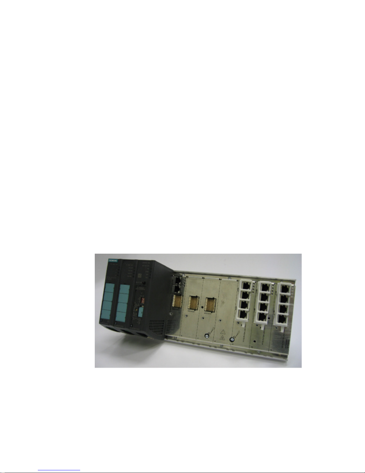
SCALANCE X414-3E basic device - overview
Overview
The SCALANCE X414-3E has two integrated gigabit Ethernet twisted pair ports (10, 100 or
1000 Mbps) to interconnect multiple switches. The nodes are connected over 12 Fast
Ethernet ports integrated in the switch (10 or 100 Mbps).
To set up optical gigabit networks, both integrated gigabit Ethernet ports can be converted to
fiber-optic cable over a 2-port gigabit Ethernet module. The module variants MM492-2 for
multimode fiber (up to 750 m), MM492-2LD (up to 10 km), MM492-2LH (up to 40 km), and
MM492-2LH+ (up to 70 km) and MM492-2ELH (up to 120 km) for single mode fiber are
available.
To set up optical Fast Ethernet networks (100 Mbps), you can insert media modules in slots
6 and/or 7. The module variants MM491-2 for multimode fiber (3 km), MM491-2LD (26 km),
and MM491-2LH+ (70 km) for single mode fiber are available.
Using the extender module EM495-8, you can expand the X414-3E device by eight Fast
Ethernet copper ports.
Using the extender module EM496-4, you can expand the X414-3E device with four Fast
Ethernet media module slots.
Figure 3-1 Basic device without media modules, protective caps and covers
Description
3.1 SCALANCE X414-3E basic device - overview
SCALANCE X-400
12 Compact Operating Instructions, 10/2013, A5E01020054-06
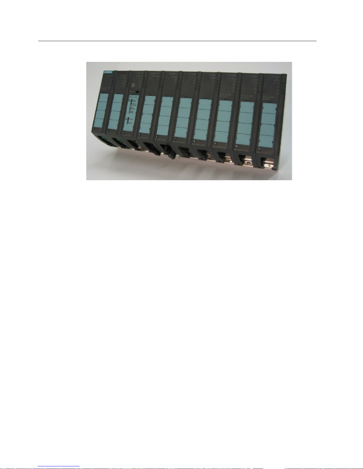
Figure 3-2 Basic device with media modules and covers
Components of the product
The following components are supplied with the SCALANCE X414-3E:
● Basic device with power module in slot 2, DI module with eight digital inputs in slot 3,
CPU module including C-PLUG in slot 4, protective caps for media module terminal
strips in slots 5, 6, and 7.
● 1 CV490 2x1000, cover of media module slot 5
2 CV490 2x100, cover of media module slots 6 and 7
1 CV490 cover, dummy cover for slot 8
3 CV490 4x100, cover for slots 9 to 11
● SIMATIC NET Manual Collection CD
● These operating instructions (compact) A5E01020054
● Slot labels for slots 1 through 18
● 1 connector for power supply (4-pin)
● 1 connector for signaling contact (4-pin)
● 2 connectors for digital inputs (5-pin)
● 1 sheet with 15 labeling strips

Description
3.1 SCALANCE X414-3E basic device - overview
SCALANCE X-400
Compact Operating Instructions, 10/2013, A5E01020054-06
13
Spare parts
● 1 C-PLUG (order number: 6GK1 900-0AB00)
● Cover set CV490 (order number: 6GK5 490-0AA00-0AA2)
– 1 cover CV490 2x1000
– 2 covers CV490 2x100
– 1 dummy cover CV490
– 3 covers CV490 4x100
● Terminal set (order number: 6GK5 498-1AA00-0AA0)
– 10 connecting terminals for power supply and signaling contact 4-pin
– 10 connecting terminals digital inputs 5-pin
● 1 location label (order number: 6ES7 912-0AA00-0AA0)
● 10 DIN A4 sheets each with 15 labeling strips
(Order number: 6GK5 498-0AA00-0AA0)
Description
3.2 SCALANCE X408-2 basic device - overview
SCALANCE X-400
14 Compact Operating Instructions, 10/2013, A5E01020054-06
3.2
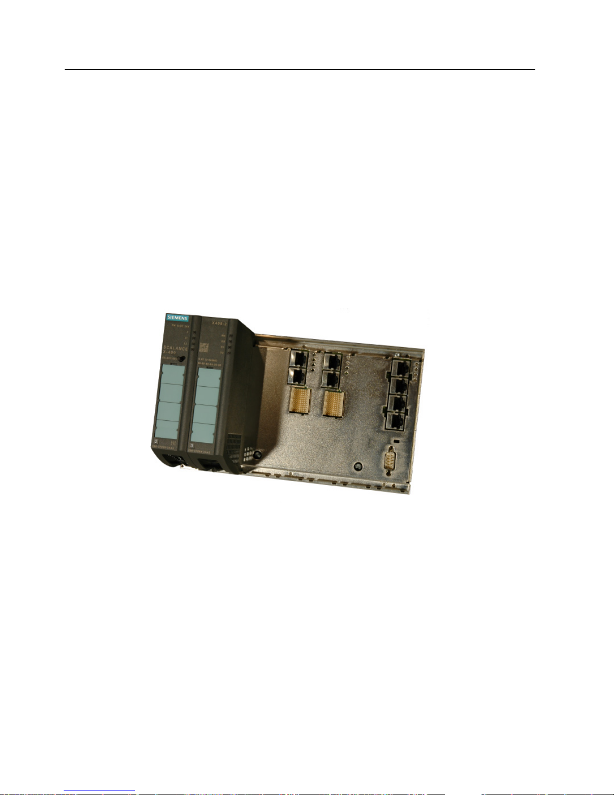
SCALANCE X408-2 basic device - overview
Overview
The SCALANCE X408-2 has four integrated gigabit Ethernet twisted-pair interfaces (10, 100
or 1000 Mbps) to interconnect multiple switches and to connect end devices. Further nodes
are connected over four Fast Ethernet ports integrated in the switch (10 or 100 Mbps).
To set up optical gigabit networks, the integrated gigabit Ethernet ports can be converted to
fiber-optic cable over a 2-port gigabit Ethernet module. The module variants MM492-2 for
multimode fiber (up to 750 m), MM492-2LD (up to 10 km), MM492-2LH (up to 40 km),
MM492-2LH+ (up to 70 km) and MM492-2ELH (up to 120 km) for single mode fiber are
available.
To set up optical Fast Ethernet networks (100 Mbps), you can also use slots 5 and/or 6 and
insert media modules. The module variants MM491-2 for multimode fiber (3 km),
MM491-2LD (26 km), and MM491-2LH+ (70 km) for single mode fiber are available.
Figure 3-3 SCALANCE X408-2 basic device without media modules, protective caps and covers

Description
3.2 SCALANCE X408-2 basic device - overview
SCALANCE X-400
Compact Operating Instructions, 10/2013, A5E01020054-06
15
Figure 3-4 SCALANCE X408-2 basic device with media modules and covers
Components of the product
The following components are supplied with the SCALANCE X408-2:
● Basic device with power module, CPU module including C-PLUG on slots 2 and 3.
Covers for media module terminal strips on slots 5 and 6.
● 2 CV490 2x1000, covers of the media module slots 5 and 6
2 CV490 cover, dummy covers for slots 4 and 7
1 CV490 4x100, cover for slot 8
● SIMATIC NET Manual Collection CD
● These operating instructions (compact) A5E01020054
● Slot labels for slots 1 through 8
● 1 connector for power supply (4-pin)
● 1 connector for signaling contact (4-pin)
● 1 sheet with 15 labeling strips

Description
3.2 SCALANCE X408-2 basic device - overview
SCALANCE X-400
16 Compact Operating Instructions, 10/2013, A5E01020054-06
Spare parts
● 1 C-PLUG (order number: 6GK1 900-0AB00)
● Cover set CV490 (order number: 6GK5 490-0AA00-0AA2)
– 1 cover CV490 2x1000
– 2 covers CV490 2x100
– 1 dummy cover CV490
– 3 covers CV490 4x100
● Terminal set (order number: 6GK5 498-1AA00-0AA0)
– 10 connecting terminals for power supply and signaling contact 4-pin
– 10 connecting terminals digital inputs 5-pin
● 1 location label (order number: 6ES7 912-0AA00-0AA0)
● 10 DIN A4 sheets each with 15 labeling strips
(Order number: 6GK5 498-0AA00-0AA0)
 Loading...