

Siemens SCALANCE XR324-12M, SCALANCE X307-2EEC, SCALANCE XR324-12M TS, SCALANCE X302-7EEC, SCALANCE XR324-4M EEC Operating Instructions Manual
...
_
_
_
_
_
_
_
_
_
_
_
_
_
_
_
_
_
_
_
_
_
_
_
_
_
SCALANCE X-300
SIMATIC NET
Industrial Ethernet Switches
SCALANCE X-300
Operating Instructions
_________________
Preface
_________________
Safety instructions
_________________
Introduction
_________________
Network topologies
_________________
Description of the device
_________________
Installation
_________________
Connecting
Configuration, displays and
_________________
display elements
_________________
Technical specifications
Approvals, certificates,
_________________
standards
______________ __ _
Accessories
______________ __ _
Graphics
__________________
Appendix
1
2
3
4
5
6
7
8
9
10
11
A
02/2012
A5E01113043-12

Legal information
Legal information
Warni
ng notice system
This manual contains notices you have to observe in order to ensure your personal safety, as well as to prevent
damage to property. The notices referring to your personal safety are highlighted in the manual by a safety alert
symbol, notices referring only to property damage have no safety alert symbol. These notices shown below are
graded according to the degree of danger.
DANGER
indicates that death or severe personal injury will result if proper precautions are not taken.
WARNING
indicates that death or severe personal injury may result if proper precautions are not taken.
CAUTION
with a safety alert symbol, indicates that minor personal injury can result if proper precautions are not taken.
CAUTION
without a safety alert symbol, indicates that property damage can result if proper precautions are not taken.
NOTICE
indicates that an unintended result or situation can occur if the relevant information is not taken into account.
If more than one degree of danger is present, the warning notice representing the highest degree of danger will
be used. A notice warning of injury to persons with a safety alert symbol may also include a warning relating to
property damage.
Qualified Personnel
The product/system described in this documentation may be operated only by personnel qualified for the specific
task in accordance with the relevant documentation, in particular its warning notices and safety instructions.
Qualified personnel are those who, based on their training and experience, are capable of identifying risks and
avoiding potential hazards when working with these products/systems.
Proper use of Siemens products
Note the following:
WARNING
Siemens products may only be used for the applications described in the catalog and in the relevant technical
documentation. If products and components from other manufacturers are used, these must be recommended
or approved by Siemens. Proper transport, storage, installation, assembly, commissioning, operation and
maintenance are required to ensure that the products operate safely and without any problems. The permissible
ambient conditions must be complied with. The information in the relevant documentation must be observed.
Trademarks
All names identified by ® are registered trademarks of Siemens AG. The remaining trademarks in this publication
may be trademarks whose use by third parties for their own purposes could violate the rights of the owner.
Disclaimer of Liability
We have reviewed the contents of this publication to ensure consistency with the hardware and software
described. Since variance cannot be precluded entirely, we cannot guarantee full consistency. However, the
information in this publication is reviewed regularly and any necessary corrections are included in subsequent
editions.
Siemens AG Order number: A5E01113043-12 Copyright © Siemens AG 2010, -,
Postfach 48 48 All rights reserved
90026 NÜRNBERG
GERMANY
2012. Industry Sector Ⓟ 02/2012 Technical data subject to change

Preface
Purpose of the Operating Instructions
These Operating Instructions describe the design and functions of the compact and modular
Industrial Ethernet Switches of the SCALANCE X-300 product line and support you during
installation, commissioning, and troubleshooting on site.
Validity of the Operating Instructions
These Operating Instructions are valid for the following product groups of the SCALANCE X300 product line, see also section Product overview (Page 21).
● X-300
● X-300M
● XR-3
00M
● X-300EEC
● XR-300M EEC
● X-300M PoE
● XR-300M PoE
● MM900 media modules
● SFP transceiver
Names of the devices in these operating instructions
Within the SCALANCE X-300 product line, there are product groups, devices and variants.
Classification Description
Product line (X-300) For all devices and variants of all product groups within the SCALANCE X-300 product
line, the term "IE Switch X-300" is used.
Product group For all devices and variants of a product group, only the product group is used.
Device For a device, only the device name is used.
Variant A variant of a device represents a particular design version. They are identified by a
separate order number.
When all variants of a device are meant in the text, "(all)" is often added after the device
name.
SCALANCE X-300
Operating Instructions, 02/2012, A5E01113043-12
3

Preface
Overview of the technical documentation of the IE Switches X-300
The technical documentation of the X-300 product line is divided into hardware and software
and can be found in the following documents:
● PH - Configuration Manual (PDF)
The software is described in the configuration manual (PH) for both product lines X-300
and X-400.
● BAK - Operating Instructions (compact) on paper
The hardware of each product group is described in the Operating Instructions (compact)
(BAK).
● BA - Operating Instructions (PDF)
The hardware for all product groups and general information can be found in the
Operating Instructions (BA).
Contents Product group Type of document Document identification number
Software
description
Hardware
description
All devices of the X-300 and X-400
product lines
All devices of the X-300 product line BA X-300 A5E01113043
X-300 BAK X-300 A5E00982643A
X-300M BAK X-300M A5E02630801A
XR-300M BAK XR-300M A5E02661171A
X-300EEC BAK X-300 EEC A5E02661176A
XR-300M EEC BAK XR-300M EEC A5E02630809A
X-300M PoE BAK X-300M PoE A5E02630810A
XR-300M PoE BAK XR-300M PoE A5E02661178A
MM900 (media modules) BAK MM900 A5E02630805A
SFP (transceivers) BAK SFP
PH X300/X400 C79000-G89000-C187
A5E02630804A
Notices leaflet
A5E02648904A
SCALANCE X-300
4 Operating Instructions, 02/2012, A5E01113043-12

Preface
Further documentation
For help on configuration and diagnostics using Web-based management, the CLI command
line interface, or SNMP, refer to the following documentation:
● Configuration Manual SCALANCE X-300 SCALANCE X-400
This configuration manual is available on the following media:
– On the supplied CD
– In 5 languages on the Internet on the pages of Siemens Automation Customer
Support under the following entry ID:
19625108 (http://support.automation.siemens.
● SIMATIC NET - Twisted Pair and Fiber Optic Networks
This manual is available on the following media:
– On paper under order numbers:
- English version: 6GK1 970-1BA10-0AA1
- German version: 6GK1 970-1BA10-0AA0
– In 5 languages on the Internet on the pages of Siemens Automation Customer
Support under the following entry ID:
8763736 (http://support.automation.siemens.
If you have questions on the use of SIMATIC NET products, please contact your Siemens
sales partner.
Standards and approvals
The devices of the SCALANCE X-300 product line meet the requirements for the CE mark.
For more detailed information, refer to section Approvals, certificates, standards (Page 223).
Integration in STEP 7 projects
The current GSDML file must be used for integration in STEP 7 V5.4 SP5 projects. This
applies to all products covered by these operating instructions.
com/WW/view/en/19625108)
com/WW/view/en/8763736)
You can obtain the relevant GSD file from the Internet at:
46183514 (http://support.automation.siemens.
You will find the file for the firmware update V3.3.1 for X-300 under entry ID "46183538".
SCALANCE X-300
Operating Instructions, 02/2012, A5E01113043-12
com/WW/view/en/46183514)
5

Preface
SCALANCE X-300
6 Operating Instructions, 02/2012, A5E01113043-12

Table of contents
Preface ...................................................................................................................................................... 3
1
Safety instructions ................................................................................................................................... 13
1.1
2
Introduction.............................................................................................................................................. 19
2.1
2.2
2.2.1
2.2.2
2.2.3
2.2.4
2.2.5
2.2.6
2.2.7
2.2.8
2.2.9
2.2.10
2.2.11
Network topologies .................................................................................................................................. 33
3
3.1
3.2
3.3
3.4
3.4.1
3.4.2
3.4.3
Important notes on using the device in hazardous areas ............................................................16
Basics of Ethernet switching........................................................................................................19
Product overview .........................................................................................................................21
Type designations........................................................................................................................21
Designs of the IE Switch X-300 devices......................................................................................23
X-300 product group ....................................................................................................................24
Product group X-300M.................................................................................................................24
Product group XR-300M ..............................................................................................................25
X-300EEC product group.............................................................................................................26
XR-300M EEC product group ......................................................................................................27
Product group X-300M PoE.........................................................................................................27
Product group XR-300M PoE ......................................................................................................28
MM900 media modules................................................................................................................29
Product overview .........................................................................................................................31
Linear structure ............................................................................................................................33
Star/tree structure ........................................................................................................................33
Ring with redundancy manager ...................................................................................................34
Options of media redundancy......................................................................................................37
Media redundancy in ring topologies ...........................................................................................37
MRP .............................................................................................................................................39
HSR..............................................................................................................................................41
3.5
4
Description of the device ......................................................................................................................... 45
4.1
4.2
4.2.1
4.2.1.1
4.2.1.2
4.2.1.3
4.2.1.4
4.2.1.5
4.2.1.6
4.2.1.7
4.2.1.8
4.2.1.9
SCALANCE X-300
Operating Instructions, 02/2012, A5E01113043-12
Redundant coupling of network segments...................................................................................42
Compatibility of SCALANCE X-300 .............................................................................................45
Product groups.............................................................................................................................47
X-300 product group ....................................................................................................................47
SCALANCE X304-2FE product characteristics ...........................................................................47
SCALANCE X306-1LD FE product characteristics......................................................................48
SCALANCE X307-3 product characteristics................................................................................49
SCALANCE X307-3LD product characteristics ...........................................................................50
SCALANCE X308-2LH product characteristics ...........................................................................51
SCALANCE X308-2LH+ product characteristics .........................................................................52
SCALANCE X310FE product characteristics ..............................................................................53
SCALANCE X308-2 product characteristics................................................................................54
SCALANCE X308-2LD product characteristics ...........................................................................55
7

Table of contents
4.2.1.10 SCALANCE X310 product characteristics .................................................................................. 56
4.2.1.11 SCALANCE X320-1FE product characteristics .......................................................................... 57
4.2.1.12
4.2.2
4.2.3
4.2.4
4.2.4.1
4.2.5
4.2.5.1
4.2.6
4.2.6.1
4.2.7
4.2.7.1
4.2.8
4.2.8.1
4.2.8.2
4.2.9
4.2.9.1
SCALANCE X320-3LD FE product characteristics..................................................................... 58
Product group X-300M................................................................................................................ 59
Product group XR-300M ............................................................................................................. 62
X-300EEC product group............................................................................................................ 64
Characteristics of the X-300EEC product group......................................................................... 64
XR-300M EEC product group ..................................................................................................... 69
SCALANCE XR324-4M EEC product characteristics................................................................. 69
Product group X-300M PoE ........................................................................................................ 71
SCALANCE X308-2M PoE product characteristics .................................................................... 71
Product group XR-300M PoE...................................................................................................... 73
SCALANCE XR324-4M PoE product characteristics ................................................................. 73
MM900 media modules............................................................................................................... 75
MM992-2M12 product characteristics......................................................................................... 76
General notes on MM900............................................................................................................ 80
SFP transceiver........................................................................................................................... 82
General notes on SFP................................................................................................................. 84
4.3
4.3.1
4.3.1.1
4.3.1.2
4.3.1.3
4.3.1.4
4.3.1.5
4.3.1.6
4.3.2
4.3.2.1
4.3.2.2
4.3.3
4.4
4.5
4.5.1
4.5.2
4.5.3
4.5.4
4.5.5
4.5.6
4.5.7
4.5.8
4.5.9
Interfaces and signaling contact of the switches ........................................................................ 85
Ethernet interfaces - electrical ports ........................................................................................... 85
10Base-T / 100Base-TX.............................................................................................................. 85
1000Base-T................................................................................................................................. 87
Power over Ethernet (PoE) ......................................................................................................... 88
Ports of the X308-2M PoE .......................................................................................................... 88
Ports of the XR-300M PoE.......................................................................................................... 89
Isolation between the TP ports ................................................................................................... 90
Ethernet interfaces - optical ports ............................................................................................... 91
1000Base-SX .............................................................................................................................. 91
1000Base-LX / 100Base-FX ....................................................................................................... 91
Signaling contact......................................................................................................................... 92
C-PLUG (configuration plug)....................................................................................................... 93
Components of the product......................................................................................................... 96
Components of the product......................................................................................................... 96
X-300M components of the product............................................................................................ 96
Components of the XR-300M product ........................................................................................ 97
X-300EEC product components ................................................................................................. 98
Components of the XR-300M EEC product................................................................................ 98
Components of the X308-2M PoE product ................................................................................. 99
Components of the XR-324-4M PoE product ........................................................................... 100
Components shipped with the MM900 product......................................................................... 100
Components shipped with the SFP product.............................................................................. 101
Installation ............................................................................................................................................. 103
5
5.1
5.2
5.2.1
5.2.2
5.2.3
5.2.4
5.2.5
SCALANCE X-300
Overview of the methods of installation .................................................................................... 104
Installing a switch ...................................................................................................................... 105
Installation on a DIN rail............................................................................................................ 105
Installation on a standard rail .................................................................................................... 107
Wall mounting ........................................................................................................................... 108
19" rack mounting ..................................................................................................................... 109
19" rack mounting - X-300EEC product group.......................................................................... 114
8 Operating Instructions, 02/2012, A5E01113043-12

Table of contents
5.2.6 19" rack mounting - XR-300M EEC product group....................................................................115
5.3 Inserting media modules and SFP transceivers ........................................................................119
5.3.1
5.3.2
Connecting ............................................................................................................................................ 125
6
Installation and removal of media modules ...............................................................................119
SFP installation in SFP media module ......................................................................................123
6.1
6.2
6.3
6.3.1
6.3.2
6.4
6.4.1
6.4.1.1
6.4.1.2
6.4.1.3
6.4.1.4
6.4.1.5
6.4.1.6
6.4.2
6.4.2.1
6.4.2.2
6.4.2.3
6.4.2.4
6.5
6.5.1
6.5.2
Configuration, displays and display elements........................................................................................ 143
7
Connecting the switch................................................................................................................125
Connecting media modules/SFPs..............................................................................................126
Connecting the grounding..........................................................................................................126
Connecting the functional ground (XR-300M EEC)...................................................................126
Grounding of the X-300EEC ......................................................................................................127
Power supply..............................................................................................................................128
24 VDC power supply ................................................................................................................128
24 VDC safety extra low voltage................................................................................................128
24 VDC - product group X-300 ..................................................................................................130
12 / 24 VDC - product group X-300M ........................................................................................130
24 VDC - product group X-300EEC...........................................................................................131
Connecting a redundant power supply to the X-300EEC..........................................................131
24 V product group XR300M PoE..............................................................................................133
100 to 240 VAC power supply ...................................................................................................134
Fitting the connector for 100 to 240 V AC..................................................................................135
Connecting the 100 to 240 VAC power supply..........................................................................137
Connecting the power supply 100 to 240 VAC to X-300EEC / XR-300M EEC.........................137
Connecting the 100 to 240 V AC power supply with the XR-300M PoE ...................................139
Signaling contact........................................................................................................................140
24 VDC signaling contact...........................................................................................................140
Signaling contact 100 to 240 VAC / 60 to 250 VDC (X-300EEC)..............................................140
7.1
7.2
7.3
7.4
7.5
8
Technical specifications......................................................................................................................... 153
8.1
8.2
8.2.1
8.2.2
8.2.3
8.2.4
8.3
8.3.1
8.3.2
8.3.3
8.3.4
SCALANCE X-300
Operating Instructions, 02/2012, A5E01113043-12
Assignment of slot numbers.......................................................................................................143
Show Location ...........................................................................................................................144
XR-300 diagnostics port.............................................................................................................144
The SET / SELECT button.........................................................................................................146
LED display................................................................................................................................147
Overview of operating temperatures for SCALANCE X-300 .....................................................153
X-300 technical specifications....................................................................................................154
Construction, installation and environmental conditions............................................................155
Connectors and electrical data ..................................................................................................156
Cable lengths .............................................................................................................................159
Other properties .........................................................................................................................161
X-300M technical specifications.................................................................................................163
Construction, installation and environmental conditions............................................................163
Connectors and electrical data ..................................................................................................165
Cable lengths .............................................................................................................................166
Other properties .........................................................................................................................167
9

Table of contents
8.4 XR-300M technical specifications ............................................................................................. 169
8.4.1 Construction, installation and environmental conditions........................................................... 169
8.4.2
8.4.3
8.4.4
8.4.5
Connectors and electrical data ................................................................................................. 171
Cable lengths ............................................................................................................................ 172
Block architecture...................................................................................................................... 173
Other properties ........................................................................................................................ 174
8.5
8.5.1
8.5.2
8.5.3
8.5.4
8.6
8.6.1
8.6.2
8.6.3
8.6.4
8.6.5
8.7
8.7.1
8.7.2
8.7.3
8.7.4
8.8
8.8.1
8.8.2
8.8.3
8.8.4
8.8.5
8.9
8.9.1
8.9.2
8.9.3
8.9.4
Technical specifications for X-300EEC..................................................................................... 175
Construction, installation and environmental conditions........................................................... 176
Connectors and electrical data ................................................................................................. 178
Cable lengths ............................................................................................................................ 180
Other properties ........................................................................................................................ 181
XR-300M EEC technical specifications..................................................................................... 183
Construction, installation and environmental conditions........................................................... 183
Connectors and electrical data ................................................................................................. 186
Cable lengths ............................................................................................................................ 188
Block architecture...................................................................................................................... 189
Other properties ........................................................................................................................ 190
X-300M PoE technical specifications........................................................................................ 191
Construction, installation and environmental conditions........................................................... 191
Connectors and electrical data ................................................................................................. 194
Cable lengths ............................................................................................................................ 196
Other properties ........................................................................................................................ 197
XR-300M PoE technical specifications ..................................................................................... 198
Construction, installation and environmental conditions........................................................... 199
Connectors and electrical data ................................................................................................. 200
Cable lengths ............................................................................................................................ 203
Block architecture...................................................................................................................... 204
Other properties ........................................................................................................................ 205
MM900 technical specifications ................................................................................................ 206
Construction, installation and environmental conditions........................................................... 206
Connectors and electrical data ................................................................................................. 208
Cable lengths ............................................................................................................................ 210
Other properties ........................................................................................................................ 212
8.10
8.10.1
8.10.2
8.10.3
8.10.4
Approvals, certificates, standards .......................................................................................................... 223
9
9.1
9.1.1
9.1.2
9.1.3
9.1.4
9.1.5
9.1.6
9.2
9.2.1
SCALANCE X-300
SFP technical specifications ..................................................................................................... 213
SFP construction, installation and environment........................................................................ 213
SFP connectors and electrical data .......................................................................................... 216
Cable lengths for SFP............................................................................................................... 219
Other properties of SFP ............................................................................................................ 221
X-300 product group ................................................................................................................. 223
Approvals, Certificates .............................................................................................................. 223
X-300 type plate ........................................................................................................................ 226
X-300 declaration of conformity ................................................................................................ 227
X-300 FDA and IEC approvals.................................................................................................. 227
Overview of the X-300 approvals.............................................................................................. 228
X-300 mechanical stability (in operation).................................................................................. 229
Product group X-300M.............................................................................................................. 229
X-300M approvals, certificates.................................................................................................. 229
10 Operating Instructions, 02/2012, A5E01113043-12

Table of contents
9.2.2 X-300M type plate......................................................................................................................233
9.2.3 X-300M conformity certificates...................................................................................................233
9.2.4
9.2.5
9.2.6
X-300M FDA and IEC approvals................................................................................................234
Overview of X-300M approvals..................................................................................................235
X-300M mechanical stability (in operation)................................................................................236
9.3
9.3.1
9.3.2
9.3.3
9.3.4
9.3.5
9.3.6
9.4
9.4.1
9.4.2
9.4.3
9.4.4
9.5
9.5.1
9.5.2
9.5.3
9.5.4
9.6
9.6.1
9.6.2
9.6.3
9.6.4
9.7
9.7.1
9.7.2
9.7.3
Product group XR-300M ............................................................................................................236
XR-300M approvals, certificates ................................................................................................236
XR-300M type plate ...................................................................................................................240
XR-300M conformity certificate..................................................................................................240
XR-300M FDA and IEC approvals.............................................................................................241
Overview of XR-300M approvals ...............................................................................................241
XR-300M mechanical stability (in operation) .............................................................................242
X-300EEC product group...........................................................................................................243
X-300EEC approvals and certificates ........................................................................................243
X-300EEC declaration of conformity..........................................................................................247
Overview of the approvals for the X-300EEC ............................................................................247
X-300EEC mechanical stability (in operation) ...........................................................................248
XR-300M EEC product group ....................................................................................................248
XR-300M EEC approvals, certificates .......................................................................................248
XR-300M EEC declaration of conformity ...................................................................................252
Overview of XR-300M EEC approvals.......................................................................................252
XR-300M EEC mechanical stability (in operation).....................................................................254
Product group X-300M PoE.......................................................................................................254
X-300M PoE approvals, certificates...........................................................................................254
X-300M PoE declaration of conformity ......................................................................................257
Overview of X-300M PoE approvals..........................................................................................258
X-300M PoE mechanical stability in operation ..........................................................................259
Product group XR-300M PoE ....................................................................................................259
XR-300M PoE approvals, certificates ........................................................................................259
X-300M PoE declaration of conformity ......................................................................................262
XR-300M PoE mechanical stability in operation........................................................................263
9.8
9.8.1
9.8.2
9.8.3
9.9
9.9.1
9.9.2
9.9.3
9.9.4
9.9.5
9.9.6
Accessories ........................................................................................................................................... 277
10
10.1
11
Graphics ................................................................................................................................................ 279
11.1
SCALANCE X-300
Operating Instructions, 02/2012, A5E01113043-12
MM900 product group................................................................................................................263
MM900 approvals, certificates ...................................................................................................263
MM900 declaration of conformity...............................................................................................266
MM900 FDA and IEC approvals ................................................................................................267
Product group SFP ....................................................................................................................268
SFP approvals, certificates ........................................................................................................268
SFP type plate............................................................................................................................271
SFP declaration of conformity....................................................................................................271
SFP FDA and IEC approvals .....................................................................................................272
Overview of the SFP approvals .................................................................................................273
SFP mechanical stability (in operation) .....................................................................................275
Accessories................................................................................................................................277
Dimension drawing ....................................................................................................................279
11

Table of contents
11.2 X-300M dimension drawings..................................................................................................... 284
11.3 XR-300M dimension drawings .................................................................................................. 286
11.4
11.5
11.6
11.7
11.8
11.9
A
Appendix................................................................................................................................................ 307
A.1
A.2
A.3
Index...................................................................................................................................................... 313
X-300EEC dimension drawings ................................................................................................ 289
XR-300M EEC dimension drawings.......................................................................................... 291
MM900 dimension drawings ..................................................................................................... 297
SFP dimension drawings .......................................................................................................... 300
X-300M PoE dimension drawings............................................................................................. 301
XR-300M PoE dimension drawings .......................................................................................... 304
TP port....................................................................................................................................... 307
Fitting the IE FC RJ-45 Plug ..................................................................................................... 309
Electrical tests (EEC devices)................................................................................................... 311
SCALANCE X-300
12 Operating Instructions, 02/2012, A5E01113043-12

Safety instructions
Safety notices on the use of the devices
The following safety notices must be adhered to when setting up and operating the device
and during all associated work such as installation, connecting up, replacing devices or
opening the device.
Safety requirements for installation
According to the UL/CSA certification, the devices are an "open type".
To fulfill requirements for safe operation with regard to mechanical stability, flame
retardation, stability, and shock-hazard protection, the following alternative types of
installation are specified:
● Installation in a suitable cabinet.
● Installation in a suitable enclosure.
● Installation in a suitably equipped, enclosed control room.
1
General information
Opening the device
DO NOT OPEN WHEN ENERGIZED.
Safety extra low voltage (only devices with 24 VDC power supply)
The equipment is designed for operation with Safety Extra-Low Voltage (SELV) by a
Limited Power Source (LPS).
This means that only SELV / LPS (Limited Power Source) complying with IEC 60950-1 / EN
60950-1 / VDE 0805-1 must be connected to the power supply terminals. The power supply
unit for the equipment power supply must comply with NEC Class 2, as described by the
National Electrical Code (r) (ANSI / NFPA 70).
There is an additional requirement if devices are operated with a redundant power supply:
If the equipment is connected to a redundant power supply (two separate power supplies),
both must meet these requirements.
WARNING
WARNING
SCALANCE X-300
Operating Instructions, 02/2012, A5E01113043-12
13
Safety instructions
General notices regarding use in hazardous areas
WARNING
Risk of explosion when connecting or disconnecting the device
EXPLOSION HAZARD
DO NOT CONNECT OR DISCONNECT EQUIPMENT WHEN A FLAMMABLE OR
COMBUSTIBLE ATMOSPHERE IS PRESENT.
WARNING
Replacing components
EXPLOSION HAZARD
SUBSTITUTION OF COMPONENTS MAY IMPAIR SUITABILITY FOR CLASS I, DIVISION
2 OR ZONE 2.
WARNING
Requirements for the cabinet/enclosure
When used in hazardous environments corresponding to Class I, Division 2 or Class I,
Zone 2, the device must be installed in a cabinet or a suitable enclosure.
SCALANCE X-300
14 Operating Instructions, 02/2012, A5E01113043-12
Safety instructions
Notices for use in hazardous areas according to ATEX
WARNING
Requirements for the cabinet/enclosure
To comply with EU Directive 94/9 (ATEX95), this enclosure must meet the requirements of
at least IP54 in compliance with EN 60529.
The fiber-optic bus connections labeled SCALANCE MM900 (see type plate) may also be
led through a hazardous area zone1 (see also MM900 approvals, certificates (Page 263),
ction "Explosion Protection Directive (ATEX)").
se
WARNING
Suitable cables for temperatures in excess of 70 °C
If the cable or conduit entry point exceeds 70°C or the branching point of conductors
exceeds 80°C, special precautions must be taken.
If the equipment is operated in an air ambient in excess of 50 °C, only use cables with
admitted maximum operating temperature of at least 80 °C.
WARNING
Protection against transient voltage surges
Provisions shall be made to prevent the rated voltage from being exceeded by transient
voltage surges of more than 40%. This criterion is fulfilled, if supplies are derived from
SELV (Safety Extra-Low Voltage) only.
See also
MM900 approvals, certificates (Page 263)
SCALANCE X-300
Operating Instructions, 02/2012, A5E01113043-12
15
Safety instructions
1.1 Important notes on using the device in hazardous areas
1.1 Important notes on using the device in hazardous areas
WARNING
WARNING - EXPLOSION HAZARD -
DO NOT DISCONNECT WHILE CIRCUIT IS LIVE UNLESS AREA IS KNOWN TO BE
NON-HAZARDOUS.
WARNING
Restricted area of application
This equipment is suitable for use in Class I, Division 2, Groups A, B, C and D or nonhazardous locations only.
WARNING
Restricted area of application
This equipment is suitable for use in Class I, Zone 2, Group IIC or non-hazardous locations
only.
Note on devices with power supply 100 to 240 V AC
DANGER
Danger from line voltage
Devices with this mark have a 100 to 240 V AC power supply.
This product can only function correctly and safely if it is transported, stored, set up, and
installed correctly, and operated and maintained as recommended.
Connecting and disconnecting may only be performed by an electrical specialist. Connect
or disconnect power supply cables only when the power is turned off!
WARNING
Devices with a 100 to 240 V AC power supply do not have an ATEX approval.
Devices with a 100 to 240 V AC power supply are not approved for use in hazardous areas
according to EC-RL-94/9 (ATEX).
CAUTION
Securing cables with dangerous voltage
Make sure that the connector cannot be released accidentally by pulling on the connecting
cable. Lay the cables in cable ducts or cable channels and secure the cables, where
necessary, with cable ties.
SCALANCE X-300
16 Operating Instructions, 02/2012, A5E01113043-12

Safety instructions
1.1 Important notes on using the device in hazardous areas
Safety requirements for installation
According to the IEC 61131-2 standard and therefore in accordance with the EU directive
2006/95/EC (Low Voltage Directive), the devices are "open equipment" and in accordance
with UL/CSA certification, they are an "open type".
To fulfill requirements for safe operation with regard to mechanical stability, flame
retardation, stability, and shock-hazard protection, the following alternative types of
installation are specified:
● Installation in a suitable cabinet.
● Installation in a suitable enclosure.
● Installation in a suitably equipped, enclosed control room.
SCALANCE X-300
Operating Instructions, 02/2012, A5E01113043-12
17

Safety instructions
1.1 Important notes on using the device in hazardous areas
SCALANCE X-300
18 Operating Instructions, 02/2012, A5E01113043-12

Introduction
2.1 Basics of Ethernet switching
Ethernet switching
Ethernet switches forward data packets directly from the input port to the appropriate output
port during data exchange based on the address information. Ethernet switches operate on a
direct delivery basis.
Essentially, switches have the following functions:
● Connecting collision domains / subnets
Since repeaters and star couplers (hubs) operate at the physical level, their use is
restricted to the span of a collision domain. Switches connect collision domains. Their use
is therefore not restricted to the maximum span of a repeater network. On the contrary,
extremely large networks with very large spans are possible with switches. The distances
achieved depend on the fiber-optic interfaces used in the devices and the FO fibers used
(see technical specifications).
● Load containment
2
By filtering the data traffic based on the Ethernet (MAC) addresses, local data traffic
remains local. In contrast to repeaters or hubs, which distribute data unfiltered to all ports
/ network nodes, switches operate selectively. Only data intended for nodes in other
subnets is switched from the input port to the appropriate output port of the switch. To
make this possible, a table assigning Ethernet (MAC) addresses to output ports is
created by the switch in a "teach-in" mode.
● Limiting the propagation of errors to the subnet involved.
By checking the validity of a data packet on the basis of the checksum which each data
packet contains, the switch ensures that bad data packets are not transported further.
Collisions in one network segment are not passed on to other segments.
The need for Industrial Ethernet switches
With over 95% of LANs based on Ethernet, this is the most commonly used technology. The
use of switches is particularly important: They allow extensive networks with large numbers
of nodes to be set up, increase the data throughput, and simplify network expansion.
The IE Switches X-300 from SIMATIC NET are designed for use in high-speed plant
networks that will also meet future requirements. With the HSR redundancy function and
standby linking of rings, high network availability can be achieved. HSR and standby link
reconfigures the network within 300 ms. Support of IT standards such as VLAN, RSTP,
IGMP, and GARP makes seamless integration of automation networks in existing office
networks possible.
The IE Switches X-300 are designed for use in switching cubicles and cabinets.
SCALANCE X-300
Operating Instructions, 02/2012, A5E01113043-12
19

Introduction
2.1 Basics of Ethernet switching
Technical options (network topologies)
The IE Switches X-300 simplify the expansion of a network regardless of the network
topology.
You can use an IE Switch X-300 in the following network topologies:
● Linear structure
● Star/tree structure
● Ring with redundancy manager
The maximum cable length is 70 km for single mode gigabit transmission. A mixed topology
consisting of IE Switch X-300 devices and OSMs/ESMs is possible at the electrical ports. A
mixed topology consisting of IE Switch X-300 devices and an OSM via the optical ports is not
possible.
Using an IE Switch X-300 as the redundancy manager in a ring with redundancy manager
provides greater availability. If there is an interruption on the connection between these
switches, the IE Switch X-300 used as redundancy manager acts like a switch and in a very
short time creates a line from the ring. As a result, a functional, end-to-end structure is
restored. For information on this topic, refer to the Configuration Manual "SIMATIC NET Industrial Ethernet Switches SCALANCE X-300 SCALANCE X-400."
SCALANCE X-300
20 Operating Instructions, 02/2012, A5E01113043-12
Introduction
2.2 Product overview
2.2 Product overview
2.2.1 Type designations
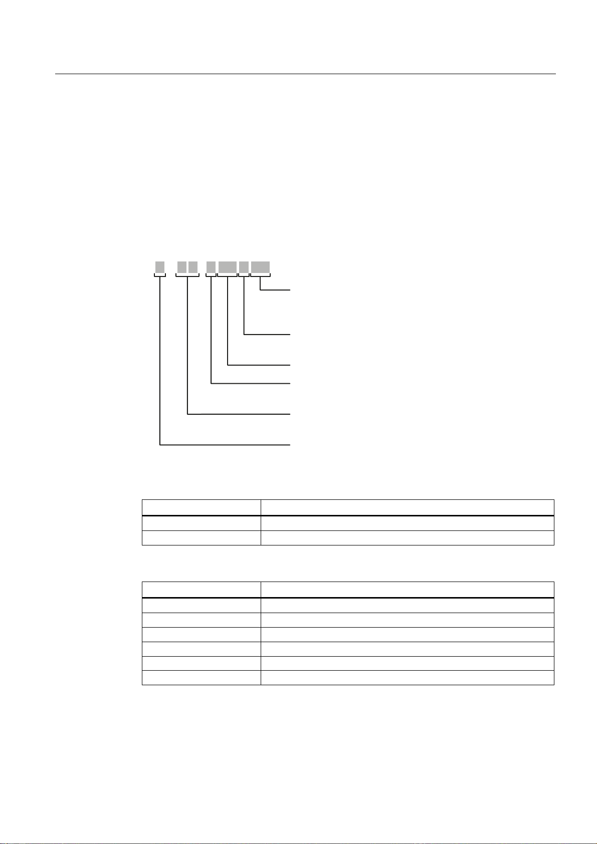
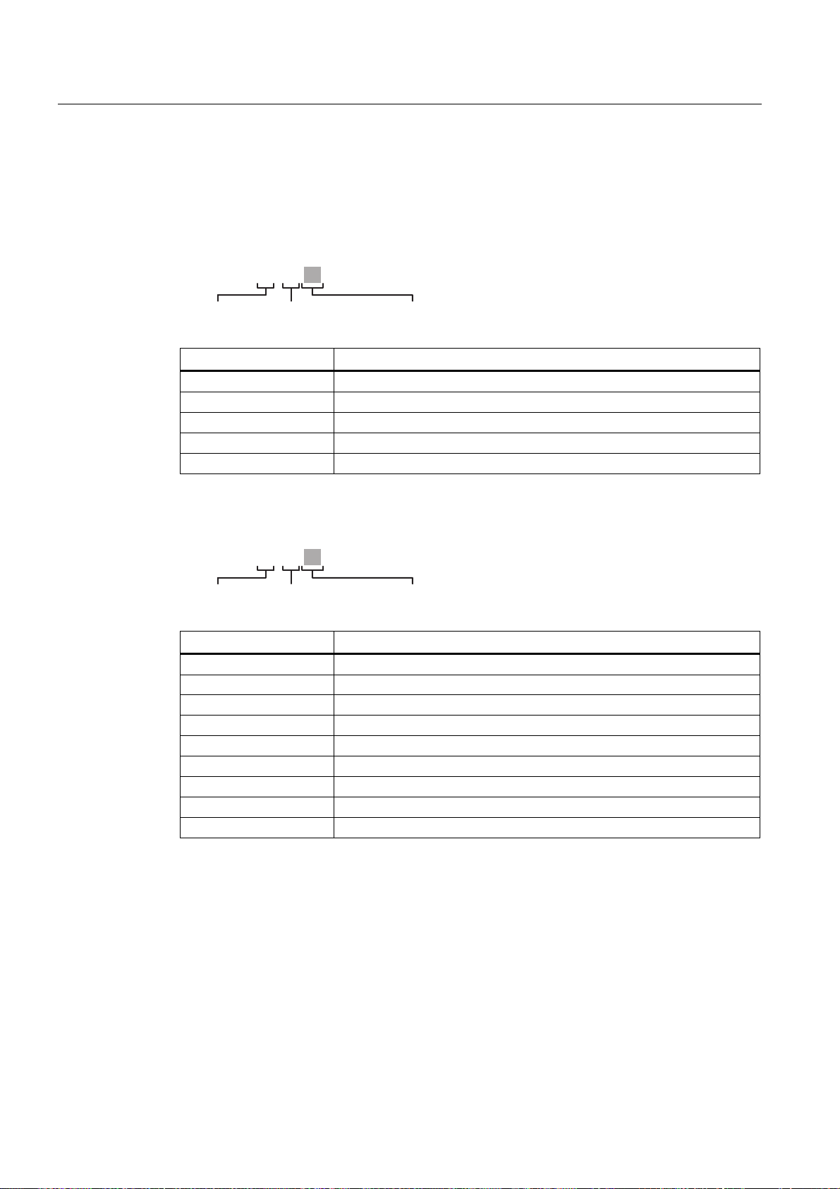
Structure of the type designation
The type designation of an IE Switch X-300 is made up of several parts that have the
following meaning:
X 3 -
EEC ([SDQGHGWHPSHUDWXUHUDQJH
PoE 3RZHURYHU(WKHUQHW
TS 7UDQVSRUWDWLRQ6\VWHP
>-@ 'HYLFHVZLWKRXWPRGXOHVORWV
M 0RGXODUGHYLFH
,QWHUIDFH
1XPEHURIRSWLFDOSRUWVRU
1XPEHURIPRGXOHVORWVZLWKPRGXODUGHYLFHV
1XPEHURIHOHFWULFDOSRUWVRU
7RWDOQXPEHURISRUWVZLWKPRGXODUGHYLFHV
>-@ &RPSDFWKRXVLQJ
R 5DFNGHYLFH
Interfaces of devices without optical ports:
Interface Property
FE Electrical RJ-45 port for 10/100 Mbps.
[-] Electrical RJ-45 port for 10/100 Mbps or 10/100/1000 Mbps.
Interfaces of devices with optical ports:
Interface Property
FE SC port 100 Mbps multimode FO cable (up to max. 5 km).
LD FE SC port 100 Mbps single mode FO cable (up to max. 26 km).
[-] SC port 1000 Mbps multimode FO cable (up to max. 750 m).
LD SC port 1000 Mbps single mode FO cable (up to max. 10 km).
LH SC port 1000 Mbps single mode FO cable (up to max. 40 km).
LH+ SC port 1000 Mbps single mode FO cable (up to max. 70 km).
SCALANCE X-300
Operating Instructions, 02/2012, A5E01113043-12
21

Introduction
2.2 Product overview
If information applies to all devices, the term "IE Switches X-300" is used. If information
applies to only a particular product group, the relevant names will be used without extra
information on the type or number of interfaces. Examples: "X-300" stands for non-modular
devices with a compact housing, "XR-300" means all rack devices, "X-300M" means all
modular devices etc.
Note
SCALANCE X320-3LD FE
The SCALANCE X320-3LD FE deviates from the type designation in that it has an SC port
for multimode fiber-optic cable up to a maximum of 5 km in length and two SC ports for
single mode fiber-optic cable up to a maximum of 26 km in length.
• Port 21: Multimode
• Port 22: LD (long distance, single mode)
• Port 23: LD (long distance, single mode)
SCALANCE X-300
22 Operating Instructions, 02/2012, A5E01113043-12
Introduction
2.2 Product overview
2.2.2 Designs of the IE Switch X-300 devices
Designs and variants of the IE Switch X-300
The IE switches of the SCALANCE X-300 product line can have the following designs and
variants:
Designs of the IE Switch X300
X Compact devices: IE switches X-300 (3 sizes: 60, 120, 180)
XR Rack devices (R): 19" IE switches (for 19" cabinet installation)
X-300EEC IE Switches X-300: 19"/2 devices (width: 216 mm)
Variant M of the IE Switch X-300
M Modular devices (M) are intended to accommodate media modules.
• Partially modular devices: Some of the ports (slots) are intended to accommodate media modules.
Example: X308-2M
• Fully modular devices: All ports (slots) are intended to accommodate media modules.
Example: XR324-12M
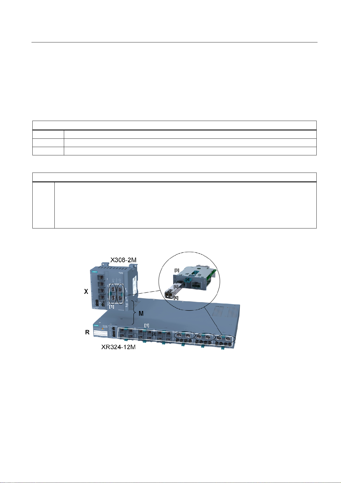
Figure 2-1 Designs of the IE Switch X-300, example with modular devices (M)
The figure shows the X308-2M and XR324-12M switches with slots for media modules
marked
SCALANCE X-300
Operating Instructions, 02/2012, A5E01113043-12
23

Introduction
2.2 Product overview
Table 2- 1 Legend
No. in
Components for the modular devices (M):
Fig.
[1] Module slots for MM900 media modules
[2] Slots for 2-port MM900 media modules
[3] SFP media module (MM992-2SFP) for MM900 media modules
The SFP transceivers (small form-factor pluggable) may only be used in the SFP media module.
[4] Grip on the media module for installing/removing
[5] SFP transceiver
[6] Clip on the SFP for installation/removal
2.2.3 X-300 product group
Type Order number
X304-2FE 6GK5 304-2BD00-2AA3
X306-1LD FE 6GK5 306-1BF00-2AA3
X307-3 6GK5 307-3BL00-2AA3
X307-3LD 6GK5 307-3BM00-2AA3
X308-2 6GK5 308-2FL00-2AA3
X308-2LD 6GK5 308-2FM00-2AA3
X308-2LH 6GK5 308-2FN00-2AA3
X308-2LH+ 6GK5 308-2FP00-2AA3
X310 6GK5 310-0FA00-2AA3
X310FE 6GK5 310-0BA00-2AA3
X320-1FE 6GK5 320-1BD00-2AA3
X320-3LD FE 6GK5 320-3BF00-2AA3
2.2.4 Product group X-300M
Product line Product
group
X-300 X-300M X308-2M (-) [6GK5 308-2GG00-2AA2]
X-300 X-300M X308-2M TS (-) [6GK5 308-2GG00-2CA2]
SCALANCE X-300
24 Operating Instructions, 02/2012, A5E01113043-12
Device:
SCALANCE
(Variant) [Order number]

Introduction
2.2 Product overview
2.2.5 Product group XR-300M
Product line Product
group
X-300 XR-300M
Device:
SCALANCE
XR324-12M (2 x 24 VDC, cable outlet front) [6GK5 324-0GG00-1AR2]
XR324-12M (1 x 100 to 240 VAC, cable
XR324-12M (2 x 24 VDC, cable outlet rear) [6GK5 324-0GG00-1HR2]
XR324-12M (1 x 100 to 240 VAC, cable
XR324-12M TS (2 x 24 VDC, cable outlet front,
(Variant) [Order number]
[6GK5 324-0GG00-3AR2]
outlet front)
[6GK5 324-0GG00-3HR2]
outlet rear)
[6GK5 324-0GG00-1CR2]
modules varnished)
SCALANCE X-300
Operating Instructions, 02/2012, A5E01113043-12
25

Introduction
2.2 Product overview
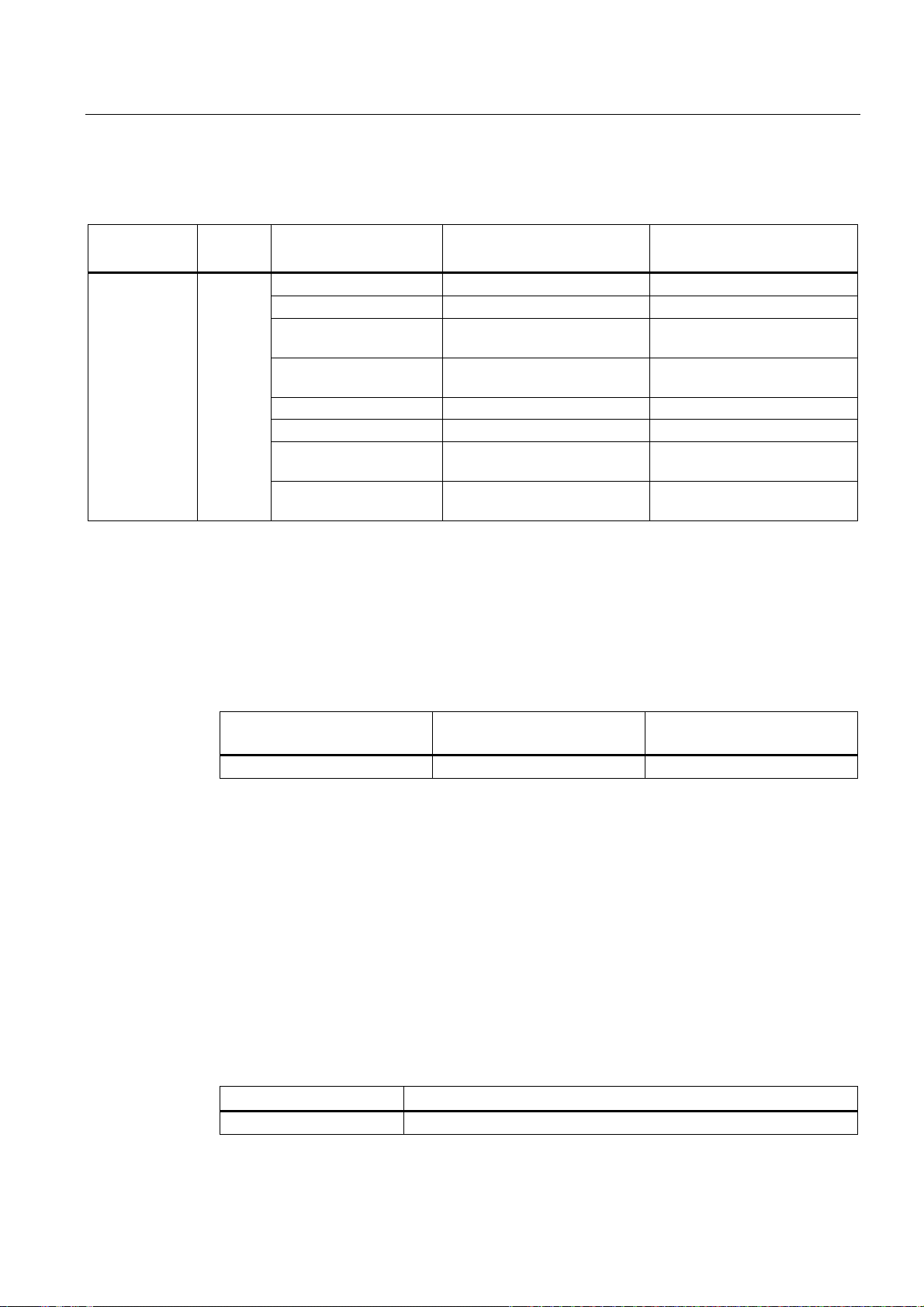
2.2.6 X-300EEC product group
The following features distinguish the different X-300EEC variants:
● 24 to 48 VDC power supply unit or multirange power supply unit 100 to 240 VAC/ 60 to
250 VDC
● Power supply unit single or double (redundant)
● Printed circuit board unvarnished or varnished (for aggressive environments)
Table 2- 2 Variants of the X-300EEC product group
Product / ports Variant Order number
X302-7EEC
• 2 electrical ports
• 7 optical ports
X307-2EEC
• 7 electrical ports
• 2 optical ports
1 x power supply unit 24 to 48 VDC 6GK5302-7GD00-1EA3
1 x power supply unit 24 to 48 VDC
Printed board varnished
2 x power supply unit 24 to 48 VDC 6GK5302-7GD00-2EA3
2 x power supply unit 24 to 48 VDC
Printed board varnished
1 x power supply unit 100 to 240 VAC / 60 to 250 VDC 6GK5302-7GD00-3EA3
1 x power supply unit 100 to 240 VAC / 60 to 250 VDC
Printed board varnished
2 x power supply unit 100 to 240 VAC / 60 to 250 VDC 6GK5302-7GD00-4EA3
2 x power supply unit 100 to 240 VAC / 60 to 250 VDC
Printed board varnished
1 x power supply unit 24 to 48 VDC 6GK5307-2FD00-1EA3
1 x power supply unit 24 to 48 VDC
Printed board varnished
2 x power supply unit 24 to 48 VDC 6GK5307-2FD00-2EA3
2 x power supply unit 24 to 48 VDC
Printed board varnished
1 x power supply unit 100 to 240 VAC / 60 to 250 VDC 6GK5307-2FD00-3EA3
1 x power supply unit 100 to 240 VAC / 60 to 250 VDC
Printed board varnished
2 x power supply unit 100 to 240 VAC / 60 to 250 VDC 6GK5307-2FD00-4EA3
2 x power supply unit 100 to 240 VAC / 60 to 250 VDC
Printed board varnished
6GK5302-7GD00-1GA3
6GK5302-7GD00-2GA3
6GK5302-7GD00-3GA3
6GK5302-7GD00-4GA3
6GK5307-2FD00-1GA3
6GK5307-2FD00-2GA3
6GK5307-2FD00-3GA3
6GK5307-2FD00-4GA3
* See naming key below
SCALANCE X-300
26 Operating Instructions, 02/2012, A5E01113043-12
Introduction
2.2 Product overview
2.2.7 XR-300M EEC product group
Product line Product
group
X-300 XR-300M
EEC
Device:
SCALANCE
XR324-4M EEC (1 x 24 VDC, cable outlet front) [6GK5 324-4GG00-1ER2]
XR324-4M EEC (2 x 24 VDC, cable outlet front) [6GK5 324-4GG00-2ER2]
XR324-4M EEC (1 x 100 to 240 VAC, cable
XR324-4M EEC (2 x 100 to 240 VAC, cable
XR324-4M EEC (1 x 24 VDC, cable outlet rear) [6GK5 324-4GG00-1JR2]
XR324-4M EEC (2 x 24 VDC, cable outlet rear) [6GK5 324-4GG00-2JR2]
XR324-4M EEC (1 x 100 to 240 VAC, cable
XR324-4M EEC (2 x 100 to 240 VAC, cable
(Variant) [Order number]
[6GK5 324-4GG00-3ER2]
outlet front)
[6GK5 324-4GG00-4ER2]
outlet front)
[6GK5 324-4GG00-3JR2]
outlet rear)
[6GK5 324-4GG00-4JR2]
outlet rear)
2.2.8 Product group X-300M PoE
Interfaces
Type RJ-45 port electrical
X308-2M PoE 4 2
Components of the product
The following parts ship with a SCALANCE X-300M PoE:
● Device with C-PLUG exchangeable medium
● 4-pin terminal block for the power supply
● 2-pin terminal block for the signaling contact
● Operating Instructions (compact)
● Product CD with documentation and software
Order numbers
Module slots
10/100/1000 Mbps
Type Order number
X308-2M PoE 6GK5 308-2QG00-2AA2
SCALANCE X-300
Operating Instructions, 02/2012, A5E01113043-12
27

Introduction
2.2 Product overview
2.2.9 Product group XR-300M PoE
Components of the product
The following parts ship with a SCALANCE XR-324-4M PoE:
● Device with C-PLUG exchangeable medium
● 2 mounting brackets and 8 screws (M3x5 recessed head, drive: Torx) for 19" rack
installation
● Connecting cable for the diagnostics port
● Operating Instructions (compact)
● Product CD with documentation and software
● For devices with a 100 to 240 VAC power supply:
– A 2-pin terminal block for the power supply
– A 2-pin terminal block for the signaling contact
● With devices with 24 V DC power supply:
– 4-pin terminal block for the power supply
– 2-pin terminal block for the signaling contact
– 4 adhesive feet for desktop mounting
SCALANCE X-300
28 Operating Instructions, 02/2012, A5E01113043-12

Introduction
2.2 Product overview
2.2.10 MM900 media modules
Type designation Interfaces [Order number]
MM992-2CUC (2 x 10/100/1000 Mbps, RJ-45 ports electrical with
MM992-2CU (2 x 10/100/1000 Mbps, RJ-45 ports electrical without
MM992-2M12 (2 x 10/100/1000 Mbps, GE M12 connector electrical) [6GK5 992-2HA00-0AA0]
MM992-2SFP (2 x 100/1000 Mbps, SFP media module) [6GK5 992-2AS00-8AA0]
MM991-2 (2 x 100 Mbps, BFOC ports optical, multimode FO
MM991-2LD (2 x 100 Mbps, BFOC ports optical, single mode FO
MM991-2 (SC) (2 x 100 Mbps, SC ports optical, multimode FO
MM991-2LD (SC) (2 x 100 Mbps, SC ports optical, single mode FO
MM991-2LH+ (SC) (2 x 100 Mbps, SC ports optical, single mode FO
MM992-2 (2 x 1000 Mbps, SC ports optical, multimode FO
MM992-2LD (2 x 1000 Mbps, SC ports optical, single mode FO
MM992-2LH (2 x 1000 Mbps, SC ports optical, single mode FO
MM992-2LH+ (2 x 1000 Mbps, SC ports optical, single mode FO
MM992-2ELH (2 x 1000 Mbps, SC ports optical, single mode FO
Note
Type designation and labeling of a media module differ
Example: The device with order number 6GK5 992-2AS00-8AA0 is called, for example,
"MM992-2SFP", the labeling on the device is "9922AS".
The labeling on the devices is shown in bold face in the following table following the [order
numbers].
Only the media module MM992-2SFP may be fitted with approved SFP transceivers. The
SFP media module can be fitted with up to two SFPs.
Labeling on the device
[6GK5 992-2GA00-8AA0]
securing collar)
securing collar)
cable, up to max. 3 km)
cable, up to max. 26 km)
cable, up to max. 3 km)
cable, up to max. 26 km)
cable, up to max. 70km)
cable, up to max. 750m)
cable, up to max. 10km)
cable, up to max. 40km)
cable, up to max. 70km)
cable, up to max. 120km)
9922GA
[6GK5 992-2SA00-8AA0]
9922SA
9922HA
9922AS
[6GK5 991-2AB00-8AA0]
9912AB
[6GK5 991-2AC00-8AA0]
9912AC
[6GK5 991-2AD00-8AA0]
9912AD
[6GK5 991-2AF00-8AA0]
9912AF
[6GK5 991-2AE00-8AA0]
9912AE
[6GK5 992-2AL00-8AA0]
9922AL
[6GK5 992-2AM00-8AA0]
9922AM
[6GK5 992-2AN00-8AA0]
9922AN
[6GK5 992-2AP00-8AA0]
9922AP
[6GK5 992-2AQ00-8AA0]
9922AQ
SCALANCE X-300
Operating Instructions, 02/2012, A5E01113043-12
29
Introduction
2.2 Product overview
Type key for the MM900 media modules
The type designation of an MM900 media module is made up of several parts that have the
following meaning:
MM991-2
100 Mbps
Interface Property
[-] BFOC port 100 Mbps multimode FO cable
LD BFOC port 100 Mbps single mode FO cable
(SC) SC port 100 Mbps multimode FO cable (up to max. 3 km)
LD (SC) SC port 100 Mbps single mode FO cable (up to max. 26 km)
LH+ (SC) SC port 100 Mbps single mode FO cable (up to max. 70 km)
Number of ports
Interface
MM992-2
1000 Mbps
Interface Property
CU RJ-45 port electrical 10/100/1000 Mbps without securing collar
CUC RJ-45 port electrical 10/100/1000 Mbps with securing collar
M12 M12 connection electrical 10/100/1000 Mbps
[-] SC port 1000 Mbps multimode FO cable (up to max. 750 m)
LD SC port 1000 Mbps single mode FO cable (up to max. 10km)
LH SC port 1000 Mbps single mode FO cable (up to max. 40 km)
LH+ SC port 1000 Mbps single mode FO cable (up to max. 70 km)
ELH SC port 1000 Mbps single mode FO cable (up to max. 120 km)
SFP SFP media module
Number of ports
Interface
SCALANCE X-300
30 Operating Instructions, 02/2012, A5E01113043-12
 Loading...