

Siemens SCALANCE X-300,SCALANCE X-400 Configuration Manual

SCALANCE X-300 / X-400
___________________
___________________
___________________
___________________
___________
___________________
___________________
___________________
___________________
___________________
___________________
___________________
___________________
___________________
SIMATIC NET
Industrial Ethernet Switches
SCALANCE X-300 / X-400
Configuration Manual
10/2014
C79000
Preface
Introduction
1
Network management for
industrial networks
2
Assignment of an IP address
3
Configuration using Web
Based Management and
Command Line Interface
4
Configuration and
diagnostics over SNMP
5
PROFINET IO functionality
6
C-PLUG
7
Firmware update
8
Appendix A
A
Appendix B
B
Appendix C
C
Appendix D
D
Appendix E
E
-G8976-C187-22

Siemens AG
Industry Sector
Postfach 48 48
90026 NÜRNBERG
GERMANY
C79000-G8976-C187-22
Ⓟ
Copyright © Siemens AG 2006 - 2014.
All rights reserved
Legal information
Warning notice system
DANGER
indicates that death or severe personal injury will result if proper precautions are not taken.
WARNING
indicates that death or severe personal injury may result if proper precautions are not taken.
CAUTION
indicates that minor personal injury can result if proper precautions are not taken.
NOTICE
indicates that property damage can result if proper precautions are not taken.
Qualified Personnel
personnel qualified
Proper use of Siemens products
WARNING
Siemens products may only be used for the applications described in the catalog and in the relevant technical
maintenance are required to ensure that the products operate safely and without any problems. The permissible
ambient conditions must be complied with. The information in the relevant documentation must be observed.
Trademarks
Disclaimer of Liability
This manual contains notices you have to observe in order to ensure your personal safety, as well as to prevent
damage to property. The notices referring to your personal safety are highlighted in the manual by a safety alert
symbol, notices referring only to property damage have no safety alert symbol. These notices shown below are
graded according to the degree of danger.
If more than one degree of danger is present, the warning notice representing the highest degree of danger will
be used. A notice warning of injury to persons with a safety alert symbol may also include a warning relating to
property damage.
The product/system described in this documentation may be operated only by
task in accordance with the relevant documentation, in particular its warning notices and safety instructions.
Qualified personnel are those who, based on their training and experience, are capable of identifying risks and
avoiding potential hazards when working with these products/systems.
Note the following:
documentation. If products and components from other manufacturers are used, these must be recommended
or approved by Siemens. Proper transport, storage, installation, assembly, commissioning, operation and
All names identified by ® are registered trademarks of Siemens AG. The remaining trademarks in this publication
may be trademarks whose use by third parties for their own purposes could violate the rights of the owner.
We have reviewed the contents of this publication to ensure consistency with the hardware and software
described. Since variance cannot be precluded entirely, we cannot guarantee full consistency. However, the
information in this publication is reviewed regularly and any necessary corrections are included in subsequent
editions.
for the specific
10/2014 Subject to change

Preface
Purpose of the manual
Validity of this manual
Names of the devices in this configuration manual
SIMATIC NET glossary
This manual supports you when configuring the SCALANCE X-300 and X-400 Industrial
Ethernet switches. It outlines the technical options provided by a SCALANCE X-300/X-400
and describes how to configure with Web Based Management and the Command Line
Interface.
This manual is valid for the following software versions:
● SCALANCE X-300/X408-2 as of firmware version 3.9.2
● SCALANCE X414-3E as of firmware version 3.10.0
● Primary Setup Tool as of version 3.1.0
● SNMP/OPC server as of version 6.2.1
This manual is valid for the following products lines:
● SCALANCE X-300
● SCALANCE X-400
Within the SCALANCE X-300 product line, there are several product groups (see also the
product overview in the "Operating Instructions Industrial Ethernet Switches SCALANCE X300").
The descriptions in this configuration manual always apply to the devices of the
SCALANCE X-300 and SCALANCE X-400 product lines listed under "Validity of the manual"
in this configuration manual unless the description relates to a specific device of the product
line. In the remainder of the description, the devices are called "IE switches".
Explanations of many of the specialist terms used in this documentation can be found in the
SIMATIC NET glossary.
You will find the SIMATIC NET glossary here:
● SIMATIC NET Manual Collection or product DVD
SCALANCE X-300 / X-400
Configuration Manual, 10/2014, C79000-G8976-C187-22
The DVD ships with certain SIMATIC NET products.
● On the Internet under the following entry ID:
50305045 (http://support.automation.siemens.com/WW/view/en/50305045
)
3

Preface
Security information
Trademarks
License conditions
Note
Open source software
Read the license conditions for open source software carefully before using the product.
Siemens provides products and solutions with industrial security functions that support the
secure operation of plants, solutions, machines, equipment and/or networks. They are
important components in a holistic industrial security concept. With this in mind, Siemens’
products and solutions undergo continuous development. Siemens recommends strongly
that you regularly check for product updates.
For the secure operation of Siemens products and solutions, it is necessary to take suitable
preventive action (e.g. cell protection concept) and integrate each component into a holistic,
state-of-the-art industrial security concept. Third-party products that may be in use should
also be considered. For more information about industrial security, visit
http://www.siemens.com/industrialsecurity
.
To stay informed about product updates as they occur, sign up for a product-specific
newsletter. For more information, visit http://support.automation.siemens.com
.
The following and possibly other names not identified by the registered trademark sign ® are
registered trademarks of Siemens AG:
SIMATIC NET, SCALANCE, C-PLUG, OLM
You will find license conditions in the following documents on the supplied data medium:
● DOC_OSS-SCALANCE-X_74.pdf
● DC_LicenseSummaryScalanceX300_76.pdf
● DC_LicenseSummaryScalanceX400_76.pdf
You will find these documents on the product DVD in the following directory: /Open Source
Information
SCALANCE X-300 / X-400
4 Configuration Manual, 10/2014, C79000-G8976-C187-22

Table of contents
Preface ................................................................................................................................................... 3
1 Introduction ............................................................................................................................................. 9
2 Network management for industrial networks ........................................................................................ 11
3 Assignment of an IP address ................................................................................................................. 25
4 Configuration using Web Based Management and Command Line Interface ......................................... 33
1.1 Technical documentation for SCALANCE X-300/X-400 ........................................................... 9
2.1 Configuration options with a SCALANCE X-300/X-400 .......................................................... 11
2.2 Functionality and properties of a SCALANCE X-300/X-400 ................................................... 12
2.3 Options of media redundancy ................................................................................................. 18
2.3.1 Media redundancy in ring topologies ...................................................................................... 18
2.3.2 MRP ........................................................................................................................................ 20
2.3.3 MRP multiple rings .................................................................................................................. 23
2.3.4 HRP......................................................................................................................................... 24
3.1 Structure of an IP address ...................................................................................................... 26
3.2 Initial assignment of an IP address ......................................................................................... 27
3.3 Assigning an IP address over the serial interface of the SCALANCE X-400 ......................... 28
3.4 Assigning addresses with the BOOTP client .......................................................................... 29
3.5 Assigning addresses with the DHCP client ............................................................................ 30
3.6 Address assignment with the Primary Setup Tool .................................................................. 31
4.1 General information on Web Based Management and Command Line Interface .................. 34
4.1.1 Introduction ............................................................................................................................. 34
4.1.2 The LED simulation of Web Based Management (WBM) ...................................................... 36
4.1.3 Working with Web Based Management .................................................................................. 38
4.1.4 Command Line Interface (CLI) ............................................................................................... 38
4.2 The System menu ................................................................................................................... 41
4.2.1 System Configuration.............................................................................................................. 41
4.2.2 System Identification & Maintenance (I&M) ............................................................................ 42
4.2.3 System Restart & Defaults ...................................................................................................... 43
4.2.4 System Save & Load via HTTP .............................................................................................. 46
4.2.5 System Save & Load via TFTP ............................................................................................... 48
4.2.6 System Version Numbers ....................................................................................................... 51
4.2.7 System Passwords & Login Mode .......................................................................................... 52
4.2.8 System Select/Set Button ....................................................................................................... 54
4.2.9 System Event Log Table ......................................................................................................... 55
4.2.10 C-PLUG Information ............................................................................................................... 57
4.2.11 Geographic coordinates .......................................................................................................... 59
4.3 The X-300/X-400 menu........................................................................................................... 61
4.3.1 X-300/X-400 Status page ....................................................................................................... 61
SCALANCE X-300 / X-400
Configuration Manual, 10/2014, C79000-G8976-C187-22
5

Table of contents
4.3.2 Ring Redundancy .................................................................................................................. 65
4.3.2.1 X-400 ring redundancy information (SCALANCE X414-3E) .................................................. 65
4.3.2.2 X-300/X-400 Ring Configuration ............................................................................................ 69
4.3.2.3 X-300/X-400 observer ............................................................................................................ 73
4.3.2.4 X-300/X-400 Standby Mask ................................................................................................... 75
4.3.2.5 X-300/X-400 Standby Observer ............................................................................................. 78
4.3.3 X-300/X-400 Fault Mask ........................................................................................................ 81
4.3.4 X-300/X-400 Counters ........................................................................................................... 83
4.4 The Agent menu..................................................................................................................... 85
4.4.1 Agent Configuration ............................................................................................................... 85
4.4.2 Ping ........................................................................................................................................ 93
4.4.3 SNMP ..................................................................................................................................... 94
4.4.3.1 Agent SNMP Configuration .................................................................................................... 94
4.4.3.2 SNMPv1 Trap Configuration .................................................................................................. 96
4.4.3.3 SNMPv3 Group Configuration ............................................................................................... 98
4.4.3.4 SNMPv3 Users Configuration .............................................................................................. 101
4.4.4 Agent Timeout Configuration ............................................................................................... 105
4.4.5 Agent Event Configuration ................................................................................................... 106
4.4.6 Agent Digital Input Configuration (SCALANCE X414-3E) ................................................... 110
4.4.7 Agent E-Mail Configuration .................................................................................................. 112
4.4.8 Agent Syslog Configuration ................................................................................................. 114
4.4.9 Agent DHCP Configuration .................................................................................................. 115
4.4.10 Time Config .......................................................................................................................... 116
4.4.10.1 Agent Time Configuration .................................................................................................... 116
4.4.10.2 SNTP Client Configuration ................................................................................................... 119
4.4.10.3 NTP Client Configuration ..................................................................................................... 121
4.4.10.4 Daylight Saving Time ........................................................................................................... 123
4.4.11 Agent PNIO Configuration ................................................................................................... 126
4.4.12 Management Access Control List ........................................................................................ 127
4.5 The Switch menu ................................................................................................................. 132
4.5.1 Switch Configuration ............................................................................................................ 133
4.5.2 Port status ............................................................................................................................ 138
4.5.3 Port Mirroring ....................................................................................................................... 144
4.5.4 Link aggregation................................................................................................................... 146
4.5.4.1 Link Aggregation .................................................................................................................. 146
4.5.4.2 LACP Configuration ............................................................................................................. 151
4.5.5 IEEE 802.1x ......................................................................................................................... 152
4.5.5.1 802.1x RADIUS Configuration ............................................................................................. 152
4.5.5.2 802.1x port parameters ........................................................................................................ 154
4.5.5.3 802.1x Port Configuration .................................................................................................... 156
4.5.6 Unicast Filter (ACL) .............................................................................................................. 159
4.5.6.1 Current Unicast Filter (Access Control List) ......................................................................... 159
4.5.6.2 Access Control List Learning ............................................................................................... 164
4.5.6.3 Access Control Port Configuration ....................................................................................... 166
4.5.6.4 Unknown Unicast Blocking Mask .........................................................................................
167
4.5.7 Multicast group ..................................................................................................................... 168
4.5.7.1 Current Multicast Groups ..................................................................................................... 168
4.5.7.2 GMRP Configuration ............................................................................................................ 173
4.5.7.3 IGMP Configuration ............................................................................................................. 174
4.5.7.4 Unknown Unicast Blocking Mask ......................................................................................... 175
4.5.8 Broadcast Blocking Mask ..................................................................................................... 176
SCALANCE X-300 / X-400
6 Configuration Manual, 10/2014, C79000-G8976-C187-22

Table of contents
4.5.9 Fast learning ......................................................................................................................... 177
4.5.10 Load Limits Configuration (SCALANCE X414-3E) ............................................................... 178
4.5.11 Load Limits Rates (SCALANCE X-300/X408-2) ................................................................... 180
4.5.12 VLAN ..................................................................................................................................... 183
4.5.12.1 Current VLAN Configuration ................................................................................................. 183
4.5.12.2 VLAN Port Parameters ......................................................................................................... 189
4.5.12.3 GVRP Configuration ............................................................................................................. 192
4.5.12.4 VLAN Learning ...................................................................................................................... 193
4.5.12.5 X-300 VLAN Port Priority Mapping ....................................................................................... 194
4.5.13 STP/RSTP ............................................................................................................................ 196
4.5.13.1 Spanning Tree Configuration ................................................................................................ 196
4.5.13.2 Spanning Tree Port Parameters ........................................................................................... 199
4.5.13.3 Spanning Tree Port Configuration ........................................................................................ 202
4.5.14 MSTP (SCALANCE X-300/X408) ......................................................................................... 205
4.5.14.1 Multiple Spanning Tree Configuration .................................................................................. 205
4.5.14.2 CIST Port Parameters........................................................................................................... 209
4.5.14.3 MSTP Instances Configuration ............................................................................................. 214
4.5.14.4 Multiple Spanning Tree Port Configuration ........................................................................... 216
4.5.15 QoS ....................................................................................................................................... 220
4.5.15.1 QoS Configuration ................................................................................................................ 220
4.5.15.2 CoS to Queue Mapping ........................................................................................................ 222
4.5.15.3 DSCP to Queue Mapping ..................................................................................................... 223
4.5.16 LLDP Configuration ............................................................................................................... 224
4.5.17 Fiber Monitoring Protocol ...................................................................................................... 226
4.5.18 DCP Configuration ................................................................................................................ 230
4.5.19 DHCP Relay Agent ............................................................................................................... 231
4.5.19.1 DHCP Relay Agent Configuration ......................................................................................... 231
4.5.19.2 DHCP Relay Agent Port Configuration ................................................................................. 233
4.5.20 Precision Time Protocol (PTP) complying with IEEE 1588 .................................................. 236
4.5.21 Configuration of the Precision Time Protocol with the WBM ................................................ 242
4.5.22 Configuration of the Precision Time Protocol with the CLI ................................................... 245
4.5.23 Port Diagnostics .................................................................................................................... 247
4.5.23.1 Cable tester (SCALANCE X-300/X408-2) ............................................................................ 247
4.5.23.2 POF ports .............................................................................................................................. 248
4.5.23.3 POF Diagnostics ................................................................................................................... 250
4.5.23.4 FM Diagnostics ..................................................................................................................... 252
4.5.23.5 SFP diagnostics .................................................................................................................... 254
4.5.24 Loop Detection ...................................................................................................................... 256
4.5.25 NAT - Network Address Translation ..................................................................................... 263
4.5.26 Statistics ................................................................................................................................ 267
4.5.26.1 Packet Size Statistic ............................................................................................................. 269
4.5.26.2 Packet Type Statistic ............................................................................................................ 272
4.5.26.3 Error Statistic ........................................................................................................................ 274
4.6 The PoE menu item .............................................................................................................. 277
4.7 The Router menu (SCALANCE X414-3E) ............................................................................ 280
4.7.1 Router Configuration .............................................................................................................
4.7.2 Router Subnets ..................................................................................................................... 282
4.7.3 Current Routes ...................................................................................................................... 284
4.7.4 RIPv2 Configuration .............................................................................................................. 288
4.7.5 RIPv2 Interfaces ................................................................................................................... 289
4.7.6 OSPFv2 Configuration .......................................................................................................... 294
SCALANCE X-300 / X-400
Configuration Manual, 10/2014, C79000-G8976-C187-22
280
7

Table of contents
5 Configuration and diagnostics over SNMP ........................................................................................... 321
6 PROFINET IO functionality .................................................................................................................. 325
7 C-PLUG ............................................................................................................................................... 355
8 Firmware update .................................................................................................................................. 357
A Appendix A .......................................................................................................................................... 363
B Appendix B .......................................................................................................................................... 367
C Appendix C .......................................................................................................................................... 375
D Appendix D .......................................................................................................................................... 377
E Appendix E .......................................................................................................................................... 383
Index ................................................................................................................................................... 401
4.7.7 OSPFv2 Areas ..................................................................................................................... 296
4.7.8 OSPFv2 Area Ranges ......................................................................................................... 299
4.7.9 OSPFv2 Interfaces ............................................................................................................... 301
4.7.10 OSPFv2 Virtual Links ........................................................................................................... 306
4.7.11 OSPFv2 Neighbors .............................................................................................................. 309
4.7.12 OSPFv2 State Database ...................................................................................................... 311
4.7.13 VRRP ................................................................................................................................... 312
4.7.14 VRRP Virtual Routers .......................................................................................................... 312
4.7.15 VRRP Associated IP Addresses .......................................................................................... 316
4.7.16 VRRP Statistics .................................................................................................................... 318
6.1 Configuring with PROFINET IO ........................................................................................... 325
6.2 Settings in HW Config .......................................................................................................... 332
6.3 Access options over PROFINET IO ..................................................................................... 337
6.4 Data record 0x802A (PDPortDataReal) ............................................................................... 346
6.5 MRP configuration ............................................................................................................... 351
8.1 Firmware update with functional firmware ........................................................................... 357
8.1.1 Firmware update over HTTP/HTTPS ................................................................................... 357
8.1.2 Firmware update over TFTP ................................................................................................ 357
8.1.3 Firmware updates over FTP ................................................................................................ 357
8.2 Firmware update using the boot software with an IE Switch X-400/XR-300 ....................... 358
8.2.1 Firmware update over the serial port ................................................................................... 359
8.2.2 Firmware update over an Ethernet port and FTP ................................................................ 362
A.1 PC attachment at the serial interface of a SCALANCE X400 .............................................. 363
A.2 PC attachment at the serial interface of a SCALANCE X300 .............................................. 365
B.1 MIB variables of a SCALANCE X300/X400 ......................................................................... 367
C.1 Tagging frames .................................................................................................................... 375
D.1 Error messages of the SCALANCE X300 / X400 ................................................................ 377
E.1 Using the same configuration on multiple IE switches......................................................... 383
SCALANCE X-300 / X-400
8 Configuration Manual, 10/2014, C79000-G8976-C187-22

1
1.1
Technical documentation for SCALANCE X-300/X-400
Content of the Configuration Manual
Topic
Chapter
with an IE switch.
have for assigning an IP address to an IE switch.
need to edit.
You want to know how to manage an IE switch with SNMP.
Chapter 5
IE switch.
PLUG.
You want to update the firmware.
Chapter 8
Content of the Operating Instructions
This manual describes the configuration of IE switches.
You will need to configure IE switches if you want to use functions such as SNMP, Rapid
Spanning Tree, VLAN, routing (SCALANCE X414-3E) or E-mail. The manual also covers the
question of firmware updates and the C-PLUG.
Before configuration, the device must be installed and connected up. You will find a
description of the necessary steps for this in the Operating Instructions.
The following table shows you which information you will find in which chapter.
You would like an overview of the documentation of an
IE switch.
You would like to know which functions and configuration options are available
You would like to know how an IP address is structured and which options you
You would like to configure an IE switch and require information on the relevant
CLI commands or want to know which pages of Web Based Management you
You want to know how you can use the options of PROFINET IO for a connected
You would like to know about the options available with the configuration plug C-
The "Operating Instructions Industrial Ethernet Switches SCALANCE X-400" and the
"Operating Instructions Industrial Ethernet Switches SCALANCE X-300" contain not only
basic information on the topic of switches but also product descriptions of IE switches, media
modules and extender modules. The instructions also describe commissioning of IE switches
(installation, wiring, using modules etc.).
Chapter 1
Chapter 2
Chapter 3
Chapter 4
Chapter 6
Chapter 7
SCALANCE X-300 / X-400
Configuration Manual, 10/2014, C79000-G8976-C187-22
9

Introduction
Overview of the technical documentation of the IE Switches X-300 and X-400
BAK
Contents
Product group
Type of document
Document identification number
scription
uct lines
PH X-300/X-400
BA X-300
X-300
BAK X-300
A5E00982643
X-300M
BAK X-300M
A5E02630801
XR-300M
BAK XR-300M
A5E02661171
X-300 EEC
BAK X-300 EEC
A5E02630809
XR-300M EEC
BAK XR-300M EEC
A5E02661176
X-300 PoE
BAK X-300 PoE
A5E02630809
XR-300M PoE
BAK XR-300M PoE
A5E02630810
MM900 (media modules)
BAK MM900
A5E02661178
BAK SFP
Notices leaflet
A5E02648904
All devices of the X-400 product line
BA X-400
C79000-G8976-C186
X-400
BAK X-400
A5E01020054
X-400EM (extender module)
BAK X-400EM
A5E00367421
X-400 media modules
BAK X-400 media modules
A5E00367420
1.1 Technical documentation for SCALANCE X-300/X-400
The technical documentation of the X-300 product line is divided into hardware and software
and can be found in the following documents:
● PH - Configuration Manual (PDF)
The software is described in the configuration manual (PH) for both product lines X-300
and X-400.
●
- Compact operating instructions on paper
The hardware of each product group is described in the Compact operating instructions
(BAK).
● BA - Operating Instructions (PDF)
The hardware for all product groups and general information can be found in the
Operating Instructions (BA).
Software de-
Hardware description
All devices of the X-300 and X-400 prod-
All devices of the X-300 product line
SFP (transceivers)
C79000-G89000-C187
A5E01113043
A5E02630804
SCALANCE X-300 / X-400
10 Configuration Manual, 10/2014, C79000-G8976-C187-22

2
2.1
Configuration options with a SCALANCE X-300/X-400
Ethernet port
Note
With the SCALANCE
band
port) on the CPU module.
RS-232 interface
Note
Access to the IE switch management over the serial port or the Ethernet port of the CPU
module is also possible when the network is disrupted (out
The IE switches can be configured over the switch ports (in-band ports) if an IP address has
already been assigned (see section "Assignment of an IP address").
Over the Ethernet interface, you can use the following protocols or services:
● Web Based Management (HTTP- and HTTPS-based)
● TELNET
● SSH
● SNMP
● Traps
● FTP
● TFTP
● E-mail
● Syslog
X414-3E, there is also a Fast Ethernet interface available (out-
The IE switches X-400/XR-300 have an RS-232 interface. You can connect a PC or PG to
this port with a null modem cable and a terminal program (for example HyperTerminal in
Windows, See also Appendix A). You use this port for the manual assignment of an IP
address for the out-band port (SCALANCE X414-3E only) or the in-band port (refer to the
Section "Assignment of an IP address over the serial port"). The entire set of CLI commands
is also available.
SCALANCE X-300 / X-400
Configuration Manual, 10/2014, C79000-G8976-C187-22
-of-band management).
11

Network management for industrial networks
2.2
Functionality and properties of a SCALANCE X-300/X-400
Integration of existing subnets with 10 Mbps and 100 Mbps
Note
Even when using strai
example by connecting two ports to an IE
and network failures.
Note
If an IE switch is connected to a partner device that does not opera
mode, the port must be set permanently to the parameters of the partner.
If both ends of the connection are not set manually, the duplex mode will not be detected.
The half duplex mode is used and results in poorer performance and col
Gigabit Ethernet ports
Note
For data transmission at 1 Gbps, at least a Cat 5e twisted
necessary. With a four
Mbps is possible.
2.2 Functionality and properties of a SCALANCE X-300/X-400
An IE switch automatically detects the following at its twisted pair ports:
● Send and receive wire pairs (autocrossover)
● Data rate (10 Mbps or 100 Mbps)
● Mode (full or half duplex)
This allows you to integrate subnets easily with IE switches over twisted pair.
ght cables, an illegal loop can occur in the Ethernet network, for
switch. Such a loop can lead to network overload
These ports are particularly suitable for a high-performance connection between switches
and have the following properties:
● Automatic detection of the send and receive cable pairs (autocrossover)
● Data rates 10 Mbps, 100 Mbps, or 1000 Mbps
● Full duplex
te in autonegotiation
lisions.
-pair cable with 4 x 2 wires is
-wire cable (2 x 2 wires), a maximum data transmission rate of 100
SCALANCE X-300 / X-400
12 Configuration Manual, 10/2014, C79000-G8976-C187-22

Network management for industrial networks
Fast redundancy in the ring
Redundant coupling of network segments
Store and Forward
Support of virtual networks (VLAN port-based)
2.2 Functionality and properties of a SCALANCE X-300/X-400
As of firmware version V3.0.0, the IE switches can handle the following redundancy
procedures:
● MRP in the ring with a maximum reconfiguration time of 200 ms
● HRP with a maximum reconfiguration time of 300 ms
Rings or linear bus structures made up of IE switches (SCALANCE X-200 or X-300/X-400 or
OSM/ESM) can be linked redundantly with suitable cabling and appropriate configuration.
(See also section "X-400 Standby Mask menu item".)
The maximum failover time is 300 ms.
For more detailed information on redundant coupling of network segments and media
redundancy in ring topologies, refer to the operating instructions "Industrial Ethernet
Switches SCALANCE X-400" or "Industrial Ethernet Switches SCALANCE X-300".
An IE switch calculates the CRC sum of incoming data packets and only forwards data with
a valid checksum (store and forward). Bad packets are not forwarded by the switch. Store
and forward also allows operation in a network on different links with different transmission
rates.
There is no physical difference between a virtual network (VLAN) and a normal LAN. The
particular feature of a VLAN is that devices can be assigned to a device group during
configuration. Several of these device groups use a network infrastructure that exists only
once physically. Several "virtual networks" result on the one physical network. Data
exchange and even the transmission of broadcasts takes place only within a VLAN.
The assignment to VLANs is achieved by expanding the frames. Four bytes of additional
information are inserted after the destination and source address. For more detailed
information on frame tagging, refer to Appendix C.
To be able to integrate end devices and subnets that do not support VLAN in virtual
networks, switches can also handle the addition and removal of the VLAN additional
information (VLAN tags). IE switches support assignment based on the port over which the
devices are connected (port-based VLAN).
● X-400
Up to 62 port-based VLANs and the two predefined VLANs can be configured. VLANs
correspond to the IEEE 802.1Q standard.
● X-300
Up to 253 port-based VLANs and the two predefined VLANs can be configured. VLANs
correspond to the IEEE 802.1Q standard.
SCALANCE X-300 / X-400
Configuration Manual, 10/2014, C79000-G8976-C187-22
13

Network management for industrial networks
Spanning Tree
Rapid Spanning Tree
Multiple Spanning Tree
C-PLUG
MAC address table
2.2 Functionality and properties of a SCALANCE X-300/X-400
The spanning tree algorithm (STP) allows network structures to be created in which there
are several connections between two stations. Spanning Tree permits exactly one path and
disables the other (redundant) ports for data traffic. This prevents loops forming in the
network. If there is an interruption, an alternative path is found via which the data is sent.
Spanning Tree is defined in the IEEE 802.1D-1998 standard.
The Rapid Spanning Tree Protocol (RSTP) is an expansion of the Spanning Tree Protocol
(STP). RSTP differs from STP essentially in that the devices are already collecting
information about alternative routes during normal operation and do not need to gather this
information after a disruption has occurred. This means that the reconfiguration time for an
RSTP controlled network can be reduced to a few seconds.
IE switches support both Rapid Spanning Tree and Spanning Tree.
Rapid Spanning Tree is defined in the IEEE 802.1D-2004 standard.
The Multiple Spanning Tree Protocol (MSTP) is a further development of the Rapid
Spanning Tree Protocol. Among other things, MSTP provides the option of operating
separate RSTP instances within different VLANs or VLAN groups. This, for example, makes
paths available within individual VLANs that the simple Rapid Spanning Tree Protocol would
block globally for data traffic.
Multiple Spanning Tree is defined in the IEEE 802.1Q standard.
The C-PLUG is an exchangeable storage medium on which all configuration information of
an IE switch is stored. When you replace an IE switch, you simply need to insert the C-PLUG
of the previous device in the new device. The new IE switch then starts up with the
configuration of the previous device.
The MAC address table of an IE switch contains information about the port or ports to which
a received frame should be forwarded. This table can contain both static entries (inserted by
the user) as well as dynamic entries (learned based on the frames received by the IE
switch).
SCALANCE X-300 / X-400
14 Configuration Manual, 10/2014, C79000-G8976-C187-22

Network management for industrial networks
Access Control
Note
In the firmware versions prior to 2.2.0, this property is called "Locked Ports".
Note
The ri
Network access protection complying with the standard IEEE 802.1x
Mirroring
E-mail function
Event log table
Time-of-day synchronization
Flow control
2.2 Functionality and properties of a SCALANCE X-300/X-400
If this function is activated for a port, an IE switch only forwards frames received at this port if
their source address exists in the address table.
It is possible to have all connected nodes entered in the access control list automatically.
ng ports cannot be configured with access control
Ports can be configured for end devices that support authentication according to IEEE
802.1x. The authentication is made via a RADIUS server that must be reachable over the
network.
Mirroring allows the data traffic of a port to be mirrored at another port. The data traffic can
then be analyzed at this monitor port without any effects on operation.
An IE switch can be configured so that it sends an E-mail when certain events occur.
The event log table logs events that occur during operation with an IE switch. The user can
specify which events cause an entry in the table.
enabled
.
IE switches allow the system time to be synchronized with external time transmitters. To use
this functionality, there must, for example, be a SICLOCK time transmitter or an SNTP server
whose frames the IE switch evaluates. Entries in the event log table then have a time stamp
that is uniform throughout the system. This allows events to be sorted according to the time
of their occurrence throughout the system speeding up the identification of the causes of
problems.
IE switches support flow control in half and full duplex mode.
SCALANCE X-300 / X-400
Configuration Manual, 10/2014, C79000-G8976-C187-22
15

Network management for industrial networks
BOOTP/DHCP
Note
If routing functions (SCALANCE X414
e
Note
DHCP and BOOTP only influence the in
configuration of the SCALANCE X414
PROFINET IO
TELNET
Note
A maximum of three simultaneous CLI connections (serial (only with an IE
and LAN) are possible.
SSH
Note
A maximum of three simultaneous CLI connections (serial (only with an IE
and LAN) are possible.
2.2 Functionality and properties of a SCALANCE X-300/X-400
IE switches can obtain their IP addresses dynamically from a BOOTP or DHCP server.
As of firmware version 2.0, the DHCP mode can be selected if DHCP is enabled. In the
previous firmware versions, DHCP is operated over the MAC address.
-3E only) are enabled, DHCP and BOOTP are not in
ffect.
-band agent IP configuration; the out-band agent IP
-3E can only be set manually.
As of firmware version 2.0, operation of the switch as a PROFINET IO device is supported.
The command line interface of an IE switch can be controlled with TELNET over a LAN or
the Internet.
Switch X-400)
The command line interface of an IE switch can be controlled with SSH over a LAN or the
Internet.
Switch X-400)
SCALANCE X-300 / X-400
16 Configuration Manual, 10/2014, C79000-G8976-C187-22

Network management for industrial networks
SNMPv3
Syslog
DHCP Option 82
IGMP Snooping and IGMP Querier
Only for SCALANCE X414-3E: Layer 3 functionality (routing)
2.2 Functionality and properties of a SCALANCE X-300/X-400
IE switches support SNMPv1, SNMPv2c, and SNMPv3. Among other things, SNMPv3
provides user management at protocol level as well as security functions (for example
authentication). The configuration of users and groups for SNMPv3 is possible using Web
Based Management, the Command Line Interface or by direct access to the MIB objects
(only recommended for experts).
Syslog according to RFC 3164 is used for transferring short, unencrypted text messages
over UDP in the IP network. This requires a standard Syslog server.
The DHCP relay function allows the IP address initialization of an end device depending on
the connected switch port. DHCP Option 82 is supported with this function.
IE switches support not only IGMP snooping but also the IGMP querier function. If IGMP
Snooping is enabled, IGMP packets are evaluated and the multicast filter table is updated
with this information. If IGMP Query is also enabled, IE switches also send IGMP queries
that trigger responses from IGMP-compliant nodes.
You can also configure the SCALANCE X414-3E as a router. This allows various IP subnets
to be interconnected. You can enter static routes and/or enable RIP/OSPF and VRRP router
protocols. Using these standardized protocols, SCALANCE X414-3E can synchronize the
configuration with other routers in the network.
SCALANCE X-300 / X-400
Configuration Manual, 10/2014, C79000-G8976-C187-22
17
Network management for industrial networks
2.3
Options of media redundancy
2.3.1
Media redundancy in ring topologies
Structure of a ring topology
Note
Before physically closing the ring, download the configuration of your STEP
individual devices.
2.3 Options of media redundancy
There are various options available to increase the network availability of an Industrial
Ethernet network with optical or electrical linear bus topologies:
● Mesh networks
● Parallel connection of transmission paths
● Closing a linear bus topology to form a ring topology
Nodes in a ring topology can be external switches and/or the integrated switches of
communications modules.
To set up a ring topology with media redundancy, you bring together the two free ends of a
linear bus topology in one device. Closing the linear bus topology to form a ring is achieved
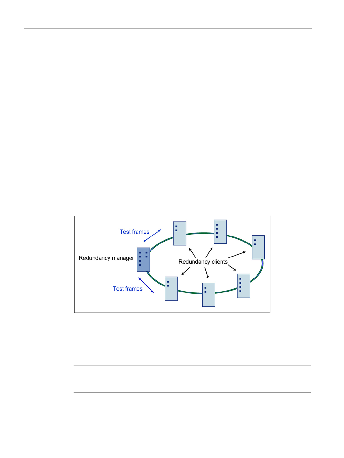
with two ports (ring ports) of a device in the ring. This device is the redundancy manager. All
other devices in the ring are redundancy clients.
Figure 2-1 Devices in a ring topology with media redundancy
The two ring ports of a device are the ports that establish the connection to its two
neighboring devices in the ring topology. The ring ports are selected and set in the
configuration of the relevant device. In STEP 7 and on the S7 Ethernet CP modules
themselves, the ring ports are indicated by an "R" after the port number.
SCALANCE X-300 / X-400
18 Configuration Manual, 10/2014, C79000-G8976-C187-22
7 project to the

Network management for industrial networks
How media redundancy works in a ring topology
Media redundancy methods
2.3 Options of media redundancy
When using media redundancy, the data paths between the individual devices are
reconfigured if the ring is interrupted at one point. Following reconfiguration of the topology,
the devices can once again be reached in the resulting new topology.
In the redundancy manager, the 2 ring ports are disconnected from each other if the network
is uninterrupted. This prevents circulating data frames. In terms of data transmission, the ring
topology is a linear bus topology. The redundancy manager monitors the ring topology. It
does this by sending test frames both from ring port 1 and ring port 2. The test frames run
round the ring in both directions until they arrive at the other ring port of the redundancy
manager.
An interruption of the ring can be caused by loss of the connection between two devices or
by failure of a device in the ring.
If the test frames of the redundancy manager no longer arrive at the other ring port because
of an interruption in the ring, the redundancy manager connects its two ring ports. This
substitute path once again restores a functioning connection between all remaining devices
in the form of a linear bus topology.
As soon as the interruption is eliminated, the original transmission paths are established
again, the two ring ports of the redundancy manager are disconnected and the redundancy
clients informed of the change. The redundancy clients then use the new paths to the other
devices.
The time between the ring interruption and restoration of a functional linear topology is
known as the reconfiguration time.
If the redundancy manager fails, the ring becomes a functional linear bus.
The following media redundancy methods are supported by SIMATIC NET products:
● HRP (High Speed Redundancy Protocol)
Reconfiguration time: 0.3 seconds
● MRP (Media Redundancy Protocol)
Reconfiguration time: 0.2 seconds
The mechanisms of these methods are similar. HRP and MRP cannot be used in the ring at
the same time.
SCALANCE X-300 / X-400
Configuration Manual, 10/2014, C79000-G8976-C187-22
19

Network management for industrial networks
2.3.2
MRP
Requirements
2.3 Options of media redundancy
The "MRP" method conforms to the Media Redundancy Protocol (MRP) specified in the
following standard:
IEC 62439-2 Edition 1.0 (2010-02) Industrial communication networks - High availability
automation networks Part 2: Media Redundancy Protocol (MRP)
The reconfiguration time after an interruption of the ring is a maximum of 0.2 seconds.
Requirements for problem-free operation with the MRP media redundancy protocol are as
follows:
● MRP is supported in ring topologies with up to 50 devices.
Except in PROFINET IO systems, topologies with up to 100 SCALANCE X-200 and
SCALANCE X-300 IE switches were tested successfully.
Exceeding this number of devices can lead to a loss of data traffic.
● The ring in which you want to use MRP may only consist of devices that support this
function.
These include, for example, some of the Industrial Ethernet SCALANCE X switches,
some of the communications processors (CPs) for SIMATIC S7 and PG/PC or nonSiemens devices that support this function.
● All devices must be interconnected via their ring ports.
Multimode connections up to 3 km and single mode connections up to 26 km between
two SCALANCE X IE switches are possible. At greater distances, the specified
reconfiguration time may be longer.
● "MRP" must be activated on all devices in the ring (see section "X-300/X-400 Ring
Configuration (Page 69)").
● The connection settings (transmission medium / duplex) must be set to full duplex and at
least 100 Mbps for all ring ports. Otherwise there may be a loss of data traffic.
– STEP 7: Set all the ports involved in the ring to "Automatic settings" in the "Options"
tab of the properties dialog.
– WBM: If you configure with Web Based Management, the ring ports are set
automatically to autonegotiation.
SCALANCE X-300 / X-400
20 Configuration Manual, 10/2014, C79000-G8976-C187-22
Network management for industrial networks
Topology
2.3 Options of media redundancy
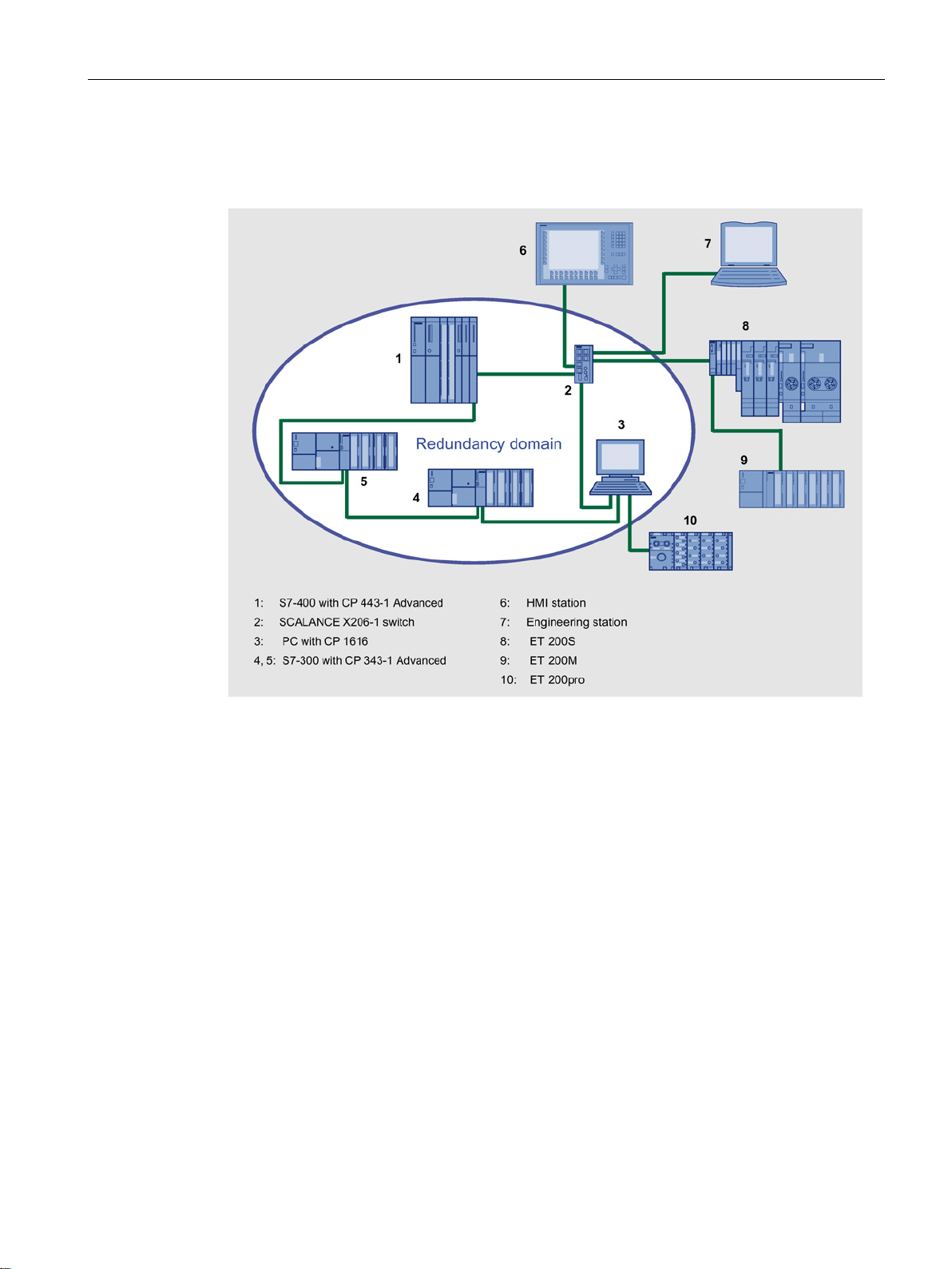
The following schematic shows a possible topology for devices in a ring with MRP.
Figure 2-2 Example of a ring topology with the MRP media redundancy protocol
The following rules apply to a ring topology with media redundancy using MRP:
● All the devices connected within the ring topology are members of the same redundancy
domain.
● One device in the ring is acting as redundancy manager.
● All other devices in the ring are redundancy clients.
Non MRP-compliant devices can be connected to the ring via a SCALANCE X switch or via
a PC with a CP 1616.
SCALANCE X-300 / X-400
Configuration Manual, 10/2014, C79000-G8976-C187-22
21

Network management for industrial networks
Devices which support MRP
Connection of SCALANCE X-300 modular switches
Note
SCALANCE X-300 - modular devices (M)
Remember that in the modular switches the ring ports are located on MM900 media
modules.
2.3 Options of media redundancy
The ring topology in which you want to use MRP may only consist of devices that support
this function. This applies, for example, to the following devices:
● Industrial Ethernet switches
– SCALANCE X-200 as of firmware version V4.0
SCALANCE X-200IRT as of firmware version V4.0
SCALANCE X-300 as of firmware version V3.0
SCALANCE X-400 as of firmware version V3.0
● Communications processors
– CP 443-1 Advanced (6GK7 443-1GX20-0XE0) as of firmware version V2.0
CP 343-1 Advanced (6GK7 343-1GX30-0XE0) as of firmware version V1.0
CP 1616 (6GK1 161-6AA00) as of firmware version V2.2
CP 1604 (6GK1 160-4AA00) as of firmware version V2.2
● Non-Siemens devices that support MRP
SCALANCE X-300 / X-400
22 Configuration Manual, 10/2014, C79000-G8976-C187-22
Network management for industrial networks
2.3.3
MRP multiple rings
Only for SCALANCE X414-3E: MRP multiple rings
2.3 Options of media redundancy
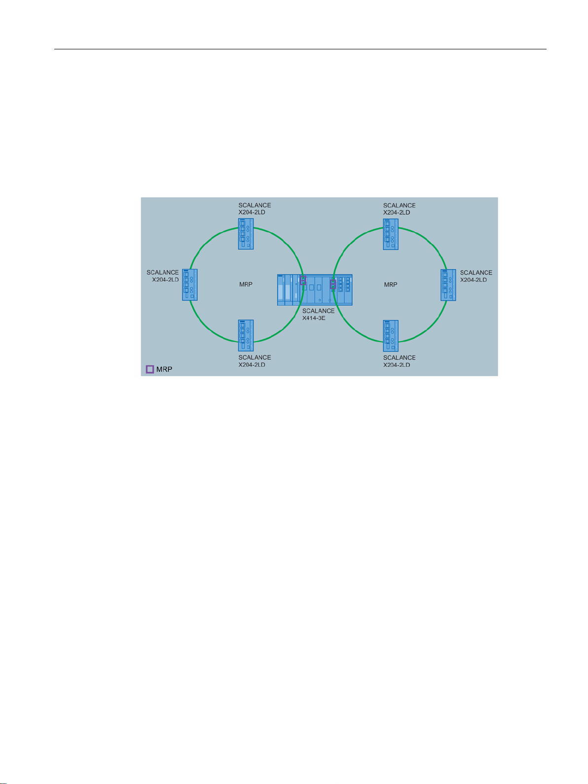
With the MRP multiple rings function, it is possible to control up to 4 MRP rings with one
central X414 redundancy manager.
MRP multiple rings can only be configured using PROFINET.
Figure 2-3 MRP multiple rings
SCALANCE X-300 / X-400
Configuration Manual, 10/2014, C79000-G8976-C187-22
23

Network management for industrial networks
2.3.4
HRP
Note
Name change
The acronym for the media redundancy protocol "High Speed Redundancy Protocol
been changed from HSR to HRP.
This is only a change of name; the functionality has not been modified. HSR and HRP nodes
can be operated together in a ring.
Requirements
2.3 Options of media redundancy
" has
The "HRP" media redundancy method allows a reconfiguration time of 0.3 seconds following
an interruption in the ring.
The following conditions must be met for problem-free operation with HRP:
● HRP is supported in ring topologies with up to 50 devices.
In topologies with SCALANCE X-200 and SCALANCE X-300 IE switches, up to 100
nodes are supported.
Exceeding this number of devices can lead to a loss of data traffic.
● The ring in which you want to use HRP may only consist of devices that support this
function. This applies, for example, to the following devices: X-400 IE switches, X-300
IE switches, X-200 IE switches and OSM/ESM.
● All devices must be interconnected via their ring ports.
Multimode connections up to 3 km and single mode connections up to 26 km between
two IE switches are possible. At greater distances, the specified reconfiguration time may
be longer.
● A device in the ring must be configured as redundancy manager by selecting the "HRP
Manager" setting. You can do this with the button on the front of the device, Web Based
Management, CLI or SNMP.
● On all other devices in the ring, either the "HRP Client" or "Automatic Redundancy
Detection" mode must be activated.
You can do this with Web Based Management, CLI or SNMP.
● In the basic status, the "HRP Client" or "Automatic Redundancy Detection" mode is set as
default.
SCALANCE X-300 / X-400
24 Configuration Manual, 10/2014, C79000-G8976-C187-22

3
Introduction
IP address types of IE switches
An IE switch provides a wide range of functions for settings and diagnostics. To access
these functions over the network, the Internet protocol is used.
The Internet protocol has its own address mechanism using IP addresses. As the protocol of
layer 3 of the ISO/OSI reference model, the IP protocol is independent of hardware allowing
flexible address assignment. In contrast to layer 2 communication (where the MAC address
is permanently assigned to a device), this makes it necessary to assign an address to a
device explicitly.
This section describes the structure of an IP address and the various options for assigning
the address with an IE switch.
IE switches can have several IP addresses:
● The out-band IP address (SCALANCE X414-3E only) is used for administration.
● The in-band agent IP address is used for administration.
● Further IP addresses
These IP addresses can only be set for routing purposes (SCALANCE X414-3E only).
They cannot be configured over DHCP but must be assigned using WBM, CLI or SNMP.
SCALANCE X-300 / X-400
Configuration Manual, 10/2014, C79000-G8976-C187-22
25

Assignment of an IP address
3.1
Structure of an IP address
Address classes to RFC 1518 and RFC 1519
IP address range
Max. number of networks
Max. number of
hosts/network
Class
CIDR
1.x.x.x through 126.x.x.x
126
16777214
A
/8
128.0.x.x through 191.255.x.x
16383
65534
B
/16
192.0.0.x through 223.255.255.x
2097151
254
C
/24
Reserved for experiments
E
Subnet mask
Note
In the bit representation of the subnet mask, the "ones" must be set left
be no "zeros" between the "ones").
3.1 Structure of an IP address
Multicast groups D
An IP address consists of 4 bytes. Each byte is represented in decimal, with a dot separating
it from the previous one. This results in the following structure, where XXX stands for a
number between 0 and 255:
XXX.XXX.XXX.XXX
The IP address is made up of two parts, the network ID and the host ID. This allows different
subnets to be created. Depending on the bytes of the IP address used as the network ID and
those used for the host ID, the IP address can be assigned to a specific address class.
The bits of the host ID can be used to create subnets. The leading bits represent the address
of the subnet and the remaining bits the address of the host in the subnet.
A subnet is defined by the subnet mask. The structure of the subnet mask corresponds to
that of an IP address. If a "1" is used at a bit position in the subnet mask, the bit belongs to
the corresponding position in the IP address of the subnet address, otherwise to the address
of the computer.
Example of a class B network:
The standard subnet address for class B networks is 255.255.0.0; in other words, the last
two bytes are available for defining a subnet. If 16 subnets must be defined, the 3rd byte of
the subnet address must be set to 11110000 (binary notation). In this case, this results in the
subnet mask 255.255.240.0.
To find out whether two IP addresses belong to the same subnet, the two IP addresses and
the subnet mask are ANDed bit by bit. If both logic operations have the save result, both IP
addresses belong to the same subnet, for example, 141.120.246.210 and 141.120.252.108.
Outside the local area network, the distinction between network ID and host ID is of no
significance, in this case packets are delivered based on the entire IP address.
-justified (there must
SCALANCE X-300 / X-400
26 Configuration Manual, 10/2014, C79000-G8976-C187-22

Assignment of an IP address
3.2
Initial assignment of an IP address
Configuration options
Note
DHCP is set as default when the module ships or following
DHCP server is available in the local area network, and this responds to the DHCP request
of the IE switch, the IP address, subnet ma
the module first starts up. DHCP and BOOTP, just like permanently set IP addresses are not
deleted by a
Note
With the SCALANCE X414
must belong to different subnets.
Example:
IP address (out
IP address (in
Subnet mask
(out
Note
The routing function is available only with the SCALANCE X414
3.2 Initial assignment of an IP address
An initial IP address for an IE switch cannot be assigned using Web Based Management or
the Command Line Interface over Telnet or SSH because these configuration tools require
that an IP address already exists.
The following options are available to assign an IP address to an unconfigured device
currently without an IP address:
● CLI over the serial port (IE Switch X-400 only)
● DHCP
● BOOTP
● STEP 7
● NCM PC
● the Primary Setup Tool (only over in-band port)
Reset to Factory Defaults
. If a
sk and gateway are assigned automatically when
Reset to Memory Defaults
.
-3E, the IP addresses of the out-band port and the in-band port
-band port): 140.90.45.66
-band port): 140.91.23.66
-band port/in band port): 255.255.0.0
With the routing function, the SCALANCE X414-3E can have more than one in-band
address. When using the Primary Setup Tool (PST), only one in-band address (the agent IP
address) can be assigned. The other addresses must be assigned with WBM, CLI, or SNMP.
SCALANCE X-300 / X-400
Configuration Manual, 10/2014, C79000-G8976-C187-22
-3E.
27

Assignment of an IP address
Note
If routing functionality is enabled, no address can be set with DH
3.3
Assigning an IP address over the serial interface of the SCALANCE
X-400
Connection over null modem cable and login
Note
If no new passwords have been assigned (def
"admin" for the administrator login and "user" for the user login with restricted permissions.
After a successful login over the serial interface, you can enter commands until you log off
with the "exit" command
5 minutes.
Note
If you lose the password, you can reset an IE Switch X
400 to the factory settings with
the SET/SEL button on the CPU module. To do this, press the SET/SEL
status display mode A (the LEDs D1 and D2 are off) for 12 seconds. You can cancel the
reset procedure by releasing the button before the 12 seconds have elapsed. All settings you
made previously are overwritten by the factory defaults.
are then valid again.
Commands for the Command Line Interface
3.3 Assigning an IP address over the serial interface of the SCALANCE X-400
CP/BOOTP.
Follow the steps outlined below to specify the IP address of an IE Switch X-400 over the
serial interface:
1. Connect the serial port of the IE Switch X-400 to a PC over a null modem cable.
2. Start a program for terminal emulation, for example the HyperTerminal program available
in Windows (settings see Appendix A).
3. Once the connection is established, the message "Login": appears. Enter "admin" (for
administrator) assuming you have this access permission and press Return.
4. When prompted for the "Password:" enter your password. Make sure you read the notes
below.
5. Enter "AGENT" when the message CLI> appears; you then change to the required
submenu. Following this, you can enter the commands for configuring the IP address.
You will find a description of these commands in the next section.
ault factory setting), the valid password is
. The session is closed automatically if there is no further activity for
-300/Xbutton in the basic
The passwords "admin" and "user"
The commands provided for the configuration of the IP address by the CLI in the submenu
AGENT are described in the section "Agent Configuration menu item".
For general information on the Command Line Interface, refer to the section "Command Line
SCALANCE X-300 / X-400
28 Configuration Manual, 10/2014, C79000-G8976-C187-22
Interface (CLI)".

Assignment of an IP address
3.4
Assigning addresses with the BOOTP client
How address assignment works
BOOTP with an IE switch
3.4 Assigning addresses with the BOOTP client
BOOTP (Bootstrap Protocol) is a protocol for the automatic assignment of IP addresses.
This type of address assignment is possible only when there is a BOOTP server in the
network.
A node without an IP address (BOOTP client) sends its MAC address with a BOOTP query
to all devices (MAC broadcast address FF-FF-FF-FF-FF-FF) on the network. The reply from
the server is also sent as a broadcast and contains not only the IP address but also the MAC
address of the client. A client that receives such a reply can recognize whether or not the IP
address is intended for it based on the MAC address.
BOOTP is based on the UDP protocol and uses UDP port 67 for the BOOTP server and port
68 for the client.
When shipped, DCP (and therefore access over the Primary Setup Tool or NCM) and DHCP
are enabled; BOOTP is disabled.
SCALANCE X-300 / X-400
Configuration Manual, 10/2014, C79000-G8976-C187-22
29

Assignment of an IP address
3.5
Assigning addresses with the DHCP client
Properties of DHCP
Note
As soon as the IP address has been assigned once by a PROFINET IO controller, DHCP
automatically deactivates itself and must be reactivated if required.
Note
DHCP uses a mechanism with which the IP address
time). If the IE switch does not reach the DHCP server for a new request on expiry of the
lease time, the assigned IP address, the subnet mask and the gateway are changed to static
entries.
The device therefore rema
DHCP server. This is not the standard behavior of office devices but is necessary for
problem
Since the DHCP client also sends a RELEASE to the server, the server
address to a further device so that inconsistencies can occur within the network.
Remedy:
After disabling DHCP, you should therefore either
•
•
Working with a mixture of dynamic address assignment and statically assigned addresses is
not advisable.
3.5 Assigning addresses with the DHCP client
DHCP (Dynamic Host Configuration Protocol) is an expansion of BOOTP; however, there
are several important differences compared with BOOTP:
● The use of DHCP is not restricted to the boot phase; DHCP can also be used during
normal operation.
● The assigned IP address remains valid only for a particular time known as the lease time.
Once this period has elapsed, the client must either request a new IP address or extend
the lease time of the existing IP address.
● There is normally no fixed address assignment; in other words, when a client requests an
IP address again, it normally receives a different address from the previous address. It is,
however possible, to configure the DHCP server so that it assigns a fixed address.
is assigned for only a short time (lease
ins accessible under the last assigned IP address even without a
-free operation of the plant.
change the IP address of the IE switch to an address not assigned by DHCP or
remove the IP address assigned to the device from the address pool of the DHCP server.
can assign this
SCALANCE X-300 / X-400
30 Configuration Manual, 10/2014, C79000-G8976-C187-22
 Loading...