

Siemens SCALANCE X-300EEC Compact Operating Instructions

SCALANCE X-300EEC
___________________
___________________
___________________
___________________
___________________
___________________
___________________
___________________
SIMATIC NET
Industrial Ethernet switches
SCALANCE X-300EEC
Compact Operating Instructions
11/2015
A5E02630809
-09
Introduction
1
Safety notes
2
Description
3
Assembling
4
Connecting
5
Technical data
6
Dimension drawings
7
Approvals
8
Siemens AG
Division Process Industries and Drives
Postfach 48 48
90026 NÜRNBERG
GERMANY
A5E02630809-09
Ⓟ
11/2015 Subject to change
Copyright © Siemens AG 2009 - 2015.
All rights reserved
Legal information
Warning notice system
This manual contains notices you have to observe in order to ensure your personal safety, as well as to prevent
damage to property. The notices referring to your personal safety are highlighted in the manual by a safety alert
symbol, notices referring only to property damage have no safety alert symbol. These notices shown below are
graded according to the degree of danger.
DANGER
indicates that death or severe personal injury will result if proper precautions are not taken.
WARNING
indicates that death or severe personal injury may result if proper precautions are not taken.
CAUTION
indicates that minor personal injury can result if proper precautions are not taken.
NOTICE
indicates that property damage can result if proper precautions are not taken.
If more than one degree of danger is present, the warning notice representing the highest degree of danger will
be used. A notice warning of injury to persons with a safety alert symbol may also include a warning relating to
property damage.
Qualified Personnel
The product/system described in this documentation may be operated only by
personnel qualified
for the specific
task in accordance with the relevant documentation, in particular its warning notices and safety instructions.
Qualified personnel are those who, based on their training and experience, are capable of identifying risks and
avoiding potential hazards when working with these products/systems.
Proper use of Siemens products
Note the following:
WARNING
Siemens products may only be used for the applications described in the catalog and in the relevant technical
documentation. If products and components from other manufacturers are used, these must be recommended
or approved by Siemens. Proper transport, storage, installation, assembly, commissioning, operation and
maintenance are required to ensure that the products operate safely and without any problems. The permissible
ambient conditions must be complied with. The information in the relevant documentation must be observed.
Trademarks
All names identified by ® are registered trademarks of Siemens AG. The remaining trademarks in this publication
may be trademarks whose use by third parties for their own purposes could violate the rights of the owner.
Disclaimer of Liability
We have reviewed the contents of this publication to ensure consistency with the hardware and software
described. Since variance cannot be precluded entirely, we cannot guarantee full consistency. However, the
information in this publication is reviewed regularly and any necessary corrections are included in subsequent
editions.

SCALANCE X-300EEC
Compact Operating Instructions, 11/2015, A5E02630809-09
3
Table of contents
1 Introduction ............................................................................................................................................. 5
1.1 X-300EEC product group .......................................................................................................... 7
1.2 Type designations ..................................................................................................................... 8
2 Safety notes .......................................................................................................................................... 11
2.1 Important notes on using devices (BA X-300) ........................................................................ 11
2.2 Important notes on using the device in hazardous areas ....................................................... 13
3 Description ............................................................................................................................................ 15
3.1 X-300EEC product components ............................................................................................. 16
3.2 Characteristics of the X-300EEC product group ..................................................................... 17
3.2.1 Ports of the X302-7EEC.......................................................................................................... 20
3.2.2 Ports of the X307-2EEC.......................................................................................................... 21
3.2.3 Signaling contact ..................................................................................................................... 22
3.3 The SET / SELECT button ...................................................................................................... 22
3.4 LED display ............................................................................................................................. 24
3.5 C-PLUG .................................................................................................................................. 28
3.5.1 Area of application and function of the C-PLUG ..................................................................... 28
3.5.2 Removing and inserting the C-PLUG (compact housing)....................................................... 29
4 Assembling ........................................................................................................................................... 31
4.1 Installation ............................................................................................................................... 31
4.2 Overview of the methods of installation .................................................................................. 32
4.3 Installation on a DIN rail .......................................................................................................... 33
4.4 Installation on a standard rail .................................................................................................. 34
4.5 Wall mounting ......................................................................................................................... 35
4.6 19" rack mounting ................................................................................................................... 36
5 Connecting ........................................................................................................................................... 39
5.1 Notes on commissioning ......................................................................................................... 39
5.2 Connecting the switch ............................................................................................................. 40
5.3 Signaling contact ..................................................................................................................... 42
5.3.1 Signaling contact 24 to 48 V ................................................................................................... 42
5.3.2 Signaling contact 100 to 240 VAC / 60 to 250 VDC ............................................................... 43
5.4 Power supply .......................................................................................................................... 44
5.4.1 Connecting devices with 24 VDC power supply ..................................................................... 44
5.4.1.1 24 VDC - product group X-300EEC ........................................................................................ 44
5.4.1.2 Connecting the external 24 VDC power supply ...................................................................... 44
5.4.1.3 Redundant power supply ........................................................................................................ 45

Table of contents
SCALANCE X-300EEC
4 Compact Operating Instructions, 11/2015, A5E02630809-09
5.4.1.4 Connecting a redundant power supply to the X-300EEC ...................................................... 46
5.4.2 Connecting devices with 100 to 240 VAC power supply ....................................................... 47
5.4.2.1 100 to 240 VAC - product group X-300EEC .......................................................................... 47
5.4.2.2 Notes on the power supply 100 to 240 VAC .......................................................................... 48
5.4.2.3 Connecting the 100 to 240 VAC power supply ...................................................................... 49
6 Technical data ...................................................................................................................................... 51
6.1 Construction, installation and environmental conditions ........................................................ 51
6.2 Connectors and electrical data .............................................................................................. 54
6.3 Cable lengths ......................................................................................................................... 56
6.4 Other properties ..................................................................................................................... 57
7 Dimension drawings .............................................................................................................................. 59
8 Approvals ............................................................................................................................................. 67
8.1 X-300EEC approvals and certificates .................................................................................... 67
8.2 Conformity certificate ............................................................................................................. 72
8.3 Overview of the approvals ..................................................................................................... 72
8.4 Mechanical stability ................................................................................................................ 73
Index .................................................................................................................................................... 75

SCALANCE X-300EEC
Compact Operating Instructions, 11/2015, A5E02630809-09
5
1
Purpose of the Operating Instructions (compact)
These operating instructions (compact) contain information with which you will be able to
install and connect up an IE Switch X-300EEC.
Validity of these Operating Instructions (compact)
These Operating Instructions (compact) are valid for the product group X-300EEC of the
SCALANCE X-300 product line.
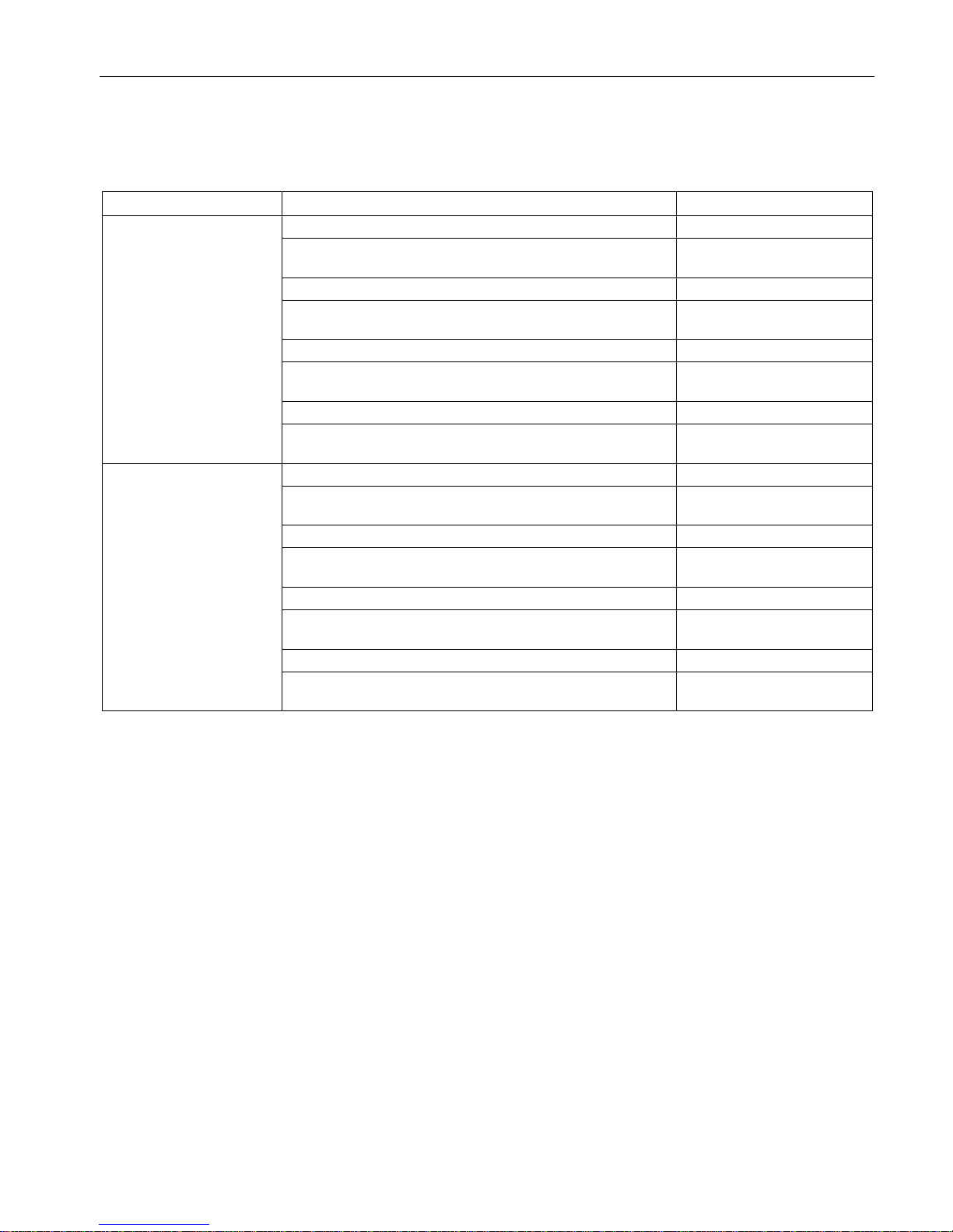
Names of the devices in these operating instructions (compact)
Classification
Description
Designation / example
Product line (X-
300)
For all devices and variants of all product groups within the SCALANCE
X-300 product line, the term "IE Switch X-300" is used.
IE Switches X-300
Product group
For all devices and variants of a product group, only the product group is
used.
X-300EEC
Device
For a device, only the device name is used. X302-7EEC
(2 electrical ports,
7 optical ports)
Variant
A variant of a device represents a particular design version. They are
identified by a separate order number.
When all variants of a device are meant in the text, "(all)" is often added
after the device name.
X302-7EEC
1 x power supply unit 24 V
DC, printed board varnished
[6GK5 302-7GD00-2EA3]
Overview of the technical documentation of the IE Switches X-300
A CD is supplied with the IE Switches X-300 on which you will find a detailed description of
the products in PDF format in the relevant subfolder.

Introduction
1.1 X-300EEC product group
SCALANCE X-300EEC
6 Compact Operating Instructions, 11/2015, A5E02630809-09
The technical documentation of the X-300 product line is divided into hardware and software
and can be found in the following documents:
● PH - Configuration Manual (PDF)
The software is described in the configuration manual (PH) for both product lines X-300
and X-400.
●
BAK
- Operating Instructions (compact) on paper
The hardware of each product group is described in the Operating Instructions (compact)
(BAK).
● BA - Operating Instructions (PDF)
The hardware for all product groups and general information can be found in the
Operating Instructions (BA).
Security messages
Note
Siemens offers IT security mechanisms for its automation and drive product portfolio in order
to support the safe operation of the plant/machine. Our products are also continuously
developed further with regard to IT security. We therefore recommend that y
ou regularly
check for updates of our products and that you only use the latest versions. You will find
information in:
(
http://support.automation.siemens.com/WW/llisapi.dll?func=cslib.csinfo2&aktprim=99&lang=
en
)
Here, you can register for a product
-specific newsletter.
For the safe operation of a plant/machine, however, it is also necessary to integrate the
automation components into an overall IT
security concept for the entire plant/machine,
which corresponds to the state
-of-the-art IT technology. You will find information on this in:
(http://www.siemens.com/industrialsecurity)
Product
s from other manufacturers that are being used must also be taken into account.
SIMATIC NET glossary
Explanations of many of the specialist terms used in this documentation can be found in the
SIMATIC NET glossary.
You will find the SIMATIC NET glossary here:
● SIMATIC NET Manual Collection or product DVD
The DVD ships with certain SIMATIC NET products.
● On the Internet under the following address:
50305045 (http://support.automation.siemens.com/WW/view/en/50305045
)
Introduction
1.1 X-300EEC product group
SCALANCE X-300EEC
Compact Operating Instructions, 11/2015, A5E02630809-09
7
1.1
X-300EEC product group
Product / ports
Properties
Order number
X302-7EEC
• 2 electrical ports
• 7 optical ports
1 x power supply unit 24 to 48 VDC
6GK5302-7GD00-1EA3
1 x power supply unit 24 to 48 VDC
Printed board varnished
6GK5302-7GD00-1GA3
2 x power supply unit 24 to 48 VDC
6GK5302-7GD00-2EA3
2 x power supply unit 24 to 48 VDC
Printed board varnished
6GK5302-7GD00-2GA3
1 x power supply unit 100 to 240 VAC / 60 to 250 VDC
6GK5302-7GD00-3EA3
1 x power supply unit 100 to 240 VAC / 60 to 250 VDC
Printed board varnished
6GK5302-7GD00-3GA3
2 x power supply unit 100 to 240 VAC / 60 to 250 VDC
6GK5302-7GD00-4EA3
2 x power supply unit 100 to 240 VAC / 60 to 250 VDC
Printed board varnished
6GK5302-7GD00-4GA3
X307-2EEC
• 7 electrical ports
• 2 optical ports
1 x power supply unit 24 to 48 VDC
6GK5307-2FD00-1EA3
1 x power supply unit 24 to 48 VDC
Printed board varnished
6GK5307-2FD00-1GA3
2 x power supply unit 24 to 48 VDC
6GK5307-2FD00-2EA3
2 x power supply unit 24 to 48 VDC
Printed board varnished
6GK5307-2FD00-2GA3
1 x power supply unit 100 to 240 VAC / 60 to 250 VDC
6GK5307-2FD00-3EA3
1 x power supply unit 100 to 240 VAC / 60 to 250 VDC
Printed board varnished
6GK5307-2FD00-3GA3
2 x power supply unit 100 to 240 VAC / 60 to 250 VDC
6GK5307-2FD00-4EA3
2 x power supply unit 100 to 240 VAC / 60 to 250 VDC
Printed board varnished
6GK5307-2FD00-4GA3
* See naming key below
Introduction
1.2 Type designations
SCALANCE X-300EEC
8 Compact Operating Instructions, 11/2015, A5E02630809-09
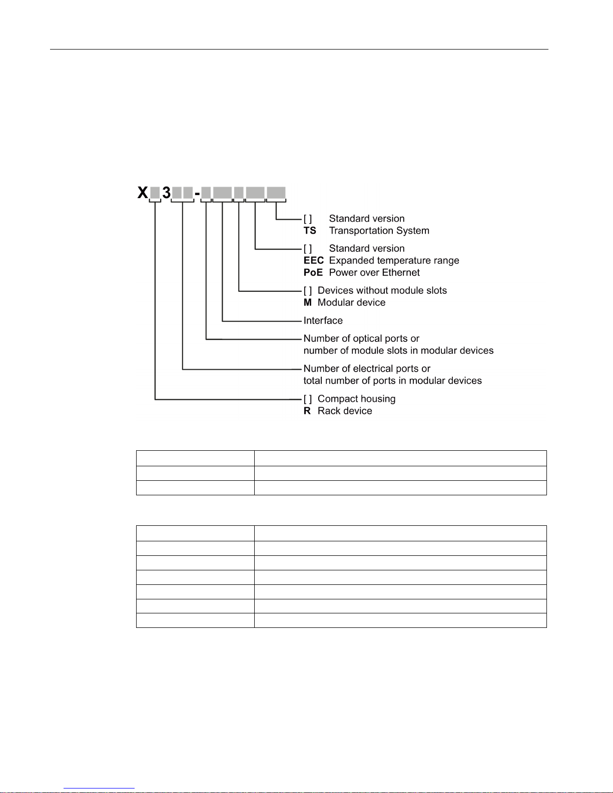
1.2
Type designations
Structure of the type designation
The type designation of an IE Switch X-300 is made up of several parts that have the
following meaning:
Interfaces of devices without optical ports:
Interface
Property
FE
Electrical RJ-45 port for 10/100 Mbps.
[-]
Electrical RJ-45 port for 10/100 Mbps or 10/100/1000 Mbps.
Interfaces of devices with optical ports:
Interface
Property
FE
SC port 100 Mbps multimode FO cable (up to max. 5 km).
LD FE
SC port 100 Mbps single mode FO cable (up to max. 26 km).
[-]
SC port 1000 Mbps multimode FO cable (up to max. 750 m).
LD
SC port 1000 Mbps single mode FO cable (up to max. 10 km).
LH
SC port 1000 Mbps single mode FO cable (up to max. 40 km).
LH+
SC port 1000 Mbps single mode FO cable (up to max. 70 km).

Introduction
1.2 Type designations
SCALANCE X-300EEC
Compact Operating Instructions, 11/2015, A5E02630809-09
9
If information applies to all devices, the term "IE Switches X-300" is used. If information
applies to only a particular product group, the relevant names will be used without extra
information on the type or number of interfaces. Examples: "X-300" stands for non-modular
devices with a compact housing, "XR-300" means all rack devices, "X-300M" means all
modular devices etc.
Note
SCALANCE X320-3LD FE
The SCALANCE X320
-3LD FE deviates from the type designation in that it has an SC port
for multimode fiber
-optic cable up to a maximum of 5 km in length and two SC ports for
single mode fiber
-optic cable up to a maximum of 26 km in length.
•
Port 21: Multimode
•
Port 22: LD (long distance, single mode)
•
Port 23: LD (long distance, single mode)

Introduction
1.2 Type designations
SCALANCE X-300EEC
10 Compact Operating Instructions, 11/2015, A5E02630809-09
SCALANCE X-300EEC
Compact Operating Instructions, 11/2015, A5E02630809-09
11
2
2.1
Important notes on using devices (BA X-300)
Safety notices on the use of the device
The following safety notices must be adhered to when setting up and operating the device
and during all associated work such as installation, connecting up, replacing or opening the
device.
General information
WARNING
Opening the device
DO NOT OPEN WHEN ENERGIZED.
WARNING
Safety extra low voltage (only devices with 24 VDC power supply)
The equipment is designed for operation with Safety Extra-Low Voltage (SELV) by a
Limited Power Source (LPS).
This means that only SELV / LPS (Limited Power Source) complying with IEC 60950-1 / EN
60950-1 / VDE 0805-1 must be connected to the power supply terminals. The power supply
unit for the equipment power supply must comply with NEC Class 2, as described by the
National Electrical Code (r) (ANSI / NFPA 70).
There is an additional requirement if devices are operated with a redundant power supply:
If the equipment is connected to a redundant power supply (two separate power supplies),
both must meet these requirements.
WARNING
For use in an environment with pollution level 2
Safety notes
2.1 Important notes on using devices (BA X-300)
SCALANCE X-300EEC
12 Compact Operating Instructions, 11/2015, A5E02630809-09
WARNING
Safety notice for connectors with LAN (Local Area Network) marking
A LAN or LAN segment, with all its associated interconnected equipment, shall be entirely
contained within a single low-voltage power distribution and within a single building. The
LAN is considered to be in an "environment A" according to IEEE802.3 or "environment 0"
according to IEC TR 62102, respectively. Never connect directly to TNV-circuits (Telephone
Network) or WAN (Wide Area Network).
General notices about use in hazardous areas
WARNING
Risk of explosion when connecting or disconnecting the device
EXPLOSION HAZARD
DO NOT CONNECT OR DISCONNECT EQUIPMENT WHEN A FLAMMABLE OR
COMBUSTIBLE ATMOSPHERE IS PRESENT.
WARNING
Replacing components
EXPLOSION HAZARD
SUBSTITUTION OF COMPONENTS MAY IMPAIR SUITABILITY FOR CLASS I, DIVISION
2 OR ZONE 2.
WARNING
Requirements for the cabinet/enclosure
When used in hazardous environments corresponding to Class I, Division 2 or Class I,
Zone 2, the device must be installed in a cabinet or a suitable enclosure.
WARNING
Opening the device
DO NOT OPEN WHEN ENERGIZED.
Safety notes
2.2 Important notes on using the device in hazardous areas
SCALANCE X-300EEC
Compact Operating Instructions, 11/2015, A5E02630809-09
13
Safety notices on use in hazardous areas according to ATEX and IECEx
WARNING
Requirements for the cabinet/enclosure
To comply with EC Directive 94/9 (ATEX95) or the conditions of IECEx, this enclosure must
meet the requirements of at least IP54 in compliance with EN 60529.
The fiber-optic bus connections labeled SCALANCE MM900 (see type plate) may also be
led through a hazardous area zone1 (see also Auto-Hotspot, section "Explosion Protection
Directive (ATEX)").
WARNING
Suitable cables for temperatures in excess of 70 °C
If the cable or conduit entry point exceeds 70°C or the branching point of conductors
exceeds 80°C, special precautions must be taken.
If the equipment is operated in an air ambient in excess of 50 °C, only use cables with
admitted maximum operating temperature of at least 80 °C.
WARNING
Protection against transient voltage surges
Provisions shall be made to prevent the rated voltage from being exceeded by transient
voltage surges of more than 40%. This criterion is fulfilled, if supplies are derived from
SELV (Safety Extra-Low Voltage) only.
2.2
Important notes on using the device in hazardous areas
WARNING
WARNING - EXPLOSION HAZARD -
DO NOT DISCONNECT WHILE CIRCUIT IS LIVE UNLESS AREA IS KNOWN TO BE
NON-HAZARDOUS.
WARNING
Restricted area of application
This equipment is suitable for use in Class I, Division 2, Groups A, B, C and D or nonhazardous locations only.
Safety notes
2.2 Important notes on using the device in hazardous areas
SCALANCE X-300EEC
14 Compact Operating Instructions, 11/2015, A5E02630809-09
WARNING
Restricted area of application
This equipment is suitable for use in Class I, Zone 2, Group IIC or non-hazardous locations
only.
Note on devices with power supply 100 to 240 V AC
WARNING
Danger from line voltage
The supply voltage for the devices listed is 100 to 240 VAC.
This device can only function correctly and safely if it is transported, stored, set up, and
installed correctly, and operated and maintained as recommended.
Connecting and disconnecting may only be performed by an electrical specialist.
Connect or disconnect power supply cables only when the power is turned off.
WARNING
Devices with a 100 to 240 V AC power supply do not have an ATEX or IECEx approval.
Devices with a 100 to 240 V AC power supply are not approved for use in hazardous areas
according to EC-RL-94/9 ATEX or IECEx.
NOTICE
Securing cables with dangerous voltage
Make sure that the connector cannot be released accidentally by pulling on the connecting
cable. Lay the cables in cable ducts or cable channels and secure the cables, where
necessary, with cable ties.
Safety requirements for installation
According to the IEC 61131-2 standard and therefore in accordance with the EU directive
2006/95/EC (Low Voltage Directive), the devices are "open equipment" and in accordance
with UL/CSA certification, they are an "open type".
To fulfill requirements for safe operation with regard to mechanical stability, flame
retardation, stability, and shock-hazard protection, the following alternative types of
installation are specified:
● Installation in a suitable cabinet.
● Installation in a suitable enclosure.
● Installation in a suitably equipped, enclosed control room.
SCALANCE X-300EEC
Compact Operating Instructions, 11/2015, A5E02630809-09
15
3
Unpacking, checking
WARNING
Do not use any parts that show evidence of damage
If you use damaged parts, there is no guarantee that the device will function according to
the specification.
If you use damaged parts, this can lead to the following problems:
• Injury to persons
• Loss of the approvals
• Violation of the EMC regulations
Use only undamaged parts.
1. Make sure that the package is complete.
2. Check all the parts for transport damage.
Description
3.1 X-300EEC product components
SCALANCE X-300EEC
16 Compact Operating Instructions, 11/2015, A5E02630809-09
3.1
X-300EEC product components
Apart from the device itself, the following components are also supplied with the switch:
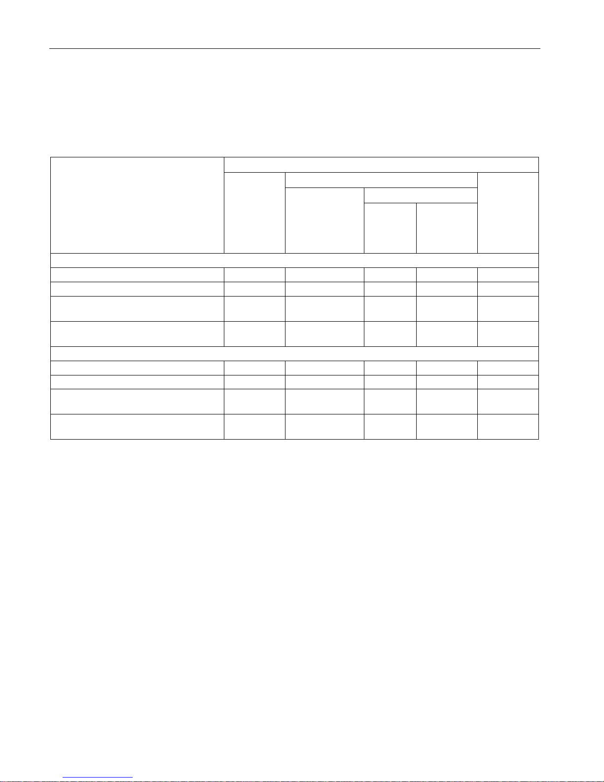
Table 3- 1 Overview of the components shipped with the X-300EEC product group
Device:
SCALANCE
(variants)
Components of the product
C-PLUG
Plug-in terminal block
Product CD
Signaling contact
with contact pins
Power
DC
24 to 48 V
AC
100 to 240 V
/ DC
60 to 250 V
X302-7EEC
1 x power supply unit 24 VDC,
●
1 x 2-pin
1 x 4-pin - ●
2 x power supply unit 24 VDC
●
2 x 2-pin
2 x 4-pin - ●
1 x power supply unit 100 to 240 VAC / 60
to 250 VDC
● 1 x 3-pin - 1 x 3-pin ●
2 x power supply unit 100 to 240 VAC / 60
to 250 VDC
● 2 x 3-pin - 2 x 3-pin ●
X307-2EEC
1 x power supply unit 24 VDC
●
1 x 2-pin
1 x 4-pin - ●
2 x power supply unit 24 VDC
●
2 x 2-pin
2 x 4-pin - ●
1 x power supply unit 100 to 240 VAC / 60
to 250 VDC
● 1 x 3-pin - 1 x 3-pin ●
2 x power supply unit 100 to 240 VAC / 60
to 250 VDC
● 2 x 3-pin - 2 x 3-pin ●

Description
3.2 Characteristics of the X-300EEC product group
SCALANCE X-300EEC
Compact Operating Instructions, 11/2015, A5E02630809-09
17
3.2
Characteristics of the X-300EEC product group
Variants
The SCALANCE X-300EEC is a 19"/2 device with 9 ports for the connection of end devices
or other network segments. There are 2 device types with the following ports:
●
SCALANCE X302-7EEC
– 2 x RJ-45 jacks
– 7 x FO ports for multimode fiber, LC connector
●
SCALANCE X307-2EEC
– 7 x RJ-45 jacks
– 2 x FO ports for multimode fiber, LC connector
Device versions
The X-300EEC is available in the following alternative versions:
●
Power supply
– Power supply unit 24 to 48 VDC
– Multirange power supply unit 100 to 240 VAC / 60 to 250 VDC
●
Power supply unit
– Single
– Redundant
●
Printed board
– Varnished (suitable for aggressive environments)
– Unvarnished
This combination of versions results in the product variants listed in section X-300EEC
product group (Page 7).
Description
3.2 Characteristics of the X-300EEC product group
SCALANCE X-300EEC
18 Compact Operating Instructions, 11/2015, A5E02630809-09
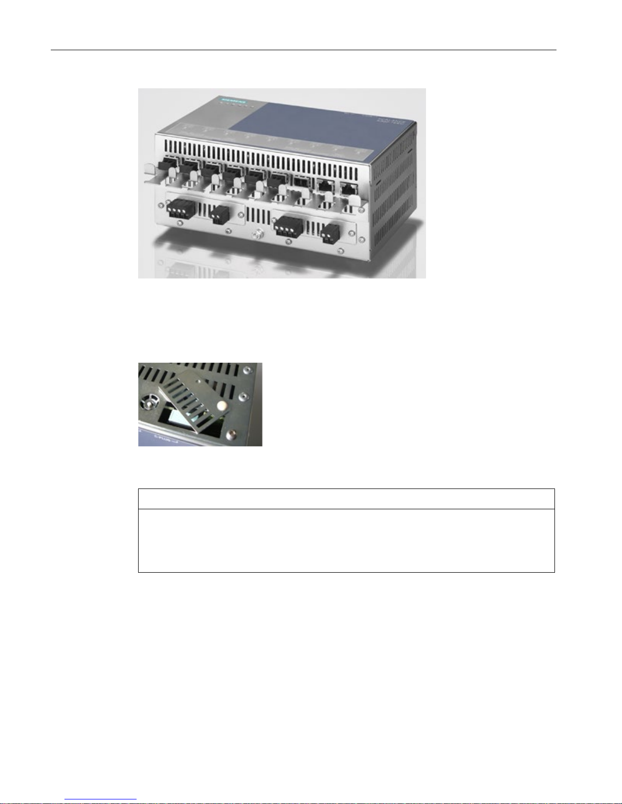
Figure 3-1 SCALANCE X302-7EEC (from below) with protective bracket and LC connector
Replacing the C-PLUG
In the X-300EEC devices, the slot for the C-PLUG is on the top on the housing.
Figure 3-2 C-PLUG of the X-300EEC
NOTICE
The C-PLUG may only be removed or inserted when the power supply to the device is
turned off.
In a device with a varnished printed circuit board, you may only use a C-PLUG with a
varnished board.
To remove the C-PLUG, open the slider and close it again after inserting the C-PLUG.

Description
3.2 Characteristics of the X-300EEC product group
SCALANCE X-300EEC
Compact Operating Instructions, 11/2015, A5E02630809-09
19
Terminal block for signaling contact and power supply
The terminal block of the X-300EEC for connecting the signaling contact and power supply
has the following terminals:
● F1, F2: Signaling contact
The 2 signaling contacts on the device version with a redundant power supply are
energized in parallel.
● L1, M1: Power supply 1
● L2, M2: Power supply 2 (redundant version)
The power supply units for the power supply are available in the following versions:
– 24 to 48 VDC
– As multirange power supply unit 100 to 240 VAC / 60 to 250 VDC
RJ-45 interface
The RJ-45 ports of the IE Switch X-300EEC are fitted with a securing bracket instead of a
securing collar.
To increase mechanical stability, secure the IE FC RJ-45 PLUGs to this securing bracket
with a cable binder.
LEDs of the X-300EEC
You will find the meaning of the individual LEDs in the Operating Instructions (BA) of the
IE Switch SCALANCE X-300.
Description
3.2 Characteristics of the X-300EEC product group
SCALANCE X-300EEC
20 Compact Operating Instructions, 11/2015, A5E02630809-09
3.2.1
Ports of the X302-7EEC
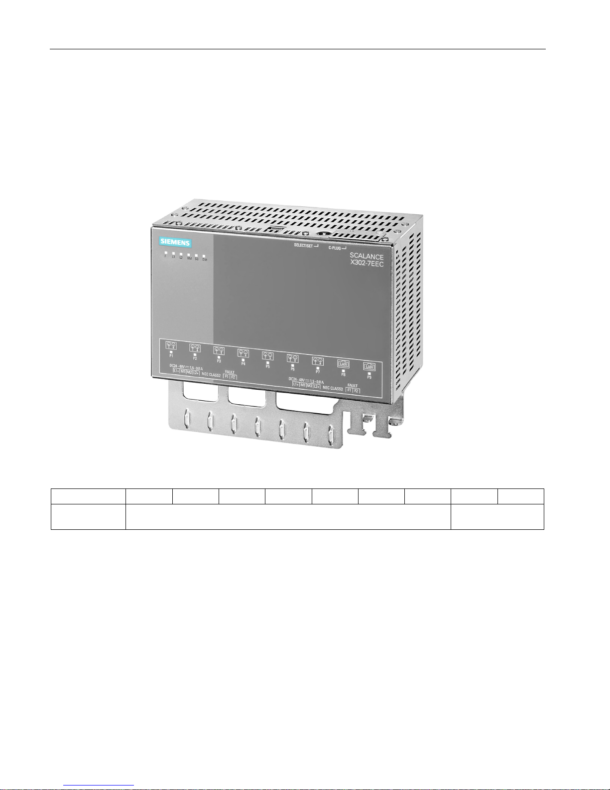
Ports of the X302-7EEC
The SCALANCE X302-7EEC has the following ports:
● 2 electrical gigabit ports (P8 to P9)
● 7 optical Fast Ethernet ports (P1 to P7)
Figure 3-3 SCALANCE X302-7EEC
Port number
P1
P2
P3
P4
P5
P6
P7
P8
P9
Connection type
Optical: Fast Ethernet Electrical: Gigabit
Ethernet
Description
3.2 Characteristics of the X-300EEC product group
SCALANCE X-300EEC
Compact Operating Instructions, 11/2015, A5E02630809-09
21
3.2.2
Ports of the X307-2EEC
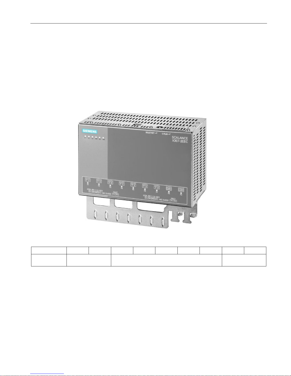
Ports of the X307-2EEC
The SCALANCE X307-2EEC has the following ports:
● 7 electrical ports (P3 to P9)
– 5 Fast Ethernet ports (P3 to P7)
– 2 gigabit ports (P8, P9)
● 2 optical Fast Ethernet ports (P1, P2)
Figure 3-4 SCALANCE X307-2EEC
Port number
P1
P2
P3
P4
P5
P6
P7
P8
P9
Connection type
Optical: Fast Ether-
net
Electrical: Fast Ethernet Electrical: Gigabit
Ethernet

Description
3.3 The SET / SELECT button
SCALANCE X-300EEC
22 Compact Operating Instructions, 11/2015, A5E02630809-09
3.2.3
Signaling contact
The signaling contact (relay contact) is a floating switch with which error/fault states can be
signaled by breaking the contact.
Error indication
● The signaling by the signaling contact is synchronized with the fault LED, in other words,
all errors displayed by this LED (freely configurable) are also signaled on the signaling
contact.
● If an internal fault occurs, the fault LED lights up and the signaling contact opens.
● The connection or disconnection of a communication node on an unmonitored port does
not lead to an error message.
● The signaling contact remains activated until the error/fault is eliminated or until the
current status is entered in the fault mask as the new desired status.
3.3
The SET / SELECT button
The SET/SELECT button is located on the top of the housing of devices of the X-300 EEC
series. On all other devices, this button is on the front panel of the housing beside the LED
display. The SET/SELECT button has several functions that are described below.
Change the display mode
By pressing the button briefly, you change to the display mode of the LED display. For more
detailed information on this topic, refer to the section "LED display".
Resetting the device to the factory defaults
If you reset, all the changes you have made will be overwritten by factory defaults. Follow the
steps outlined below:
1. Turn on display mode A. Display mode A is active when the "DM" LED is not lit. If this
LED is lit or flashing, you will need to press the SET/SELECT briefly (possibly several
times) until the "DM" LED goes off. If the SELECT/SET button is not pressed for longer
than a minute, the device also turns on display mode A.
2. Hold down the SELECT/SET button for 12 seconds. If you release the button before the
12 seconds have elapsed, the reset is canceled.

Description
3.3 The SET / SELECT button
SCALANCE X-300EEC
Compact Operating Instructions, 11/2015, A5E02630809-09
23
Definition of the fault mask
Using the fault mask, you specify an individual "good status" for the connected ports and the
power supply. Deviations from this status are then displayed as errors/faults.
1. Turn on display mode A or D. Display mode A is active when the "DM" LED is not lit.
Display mode D is active when the "DM" LED flashes yellow/orange. If a different display
mode is active, you will need to press the SET/SELECT briefly (possibly several times)
until the required display mode is active.
2. Hold down the SET/SELECT button for five seconds. After three seconds, the "DM" LED
begins to flash. If you release the button before the five seconds have elapsed, the
previous fault mask will be retained.
Enable/disable the redundancy manager
1. Turn on display mode B. Display mode B is active when the "DM" LED is lit green. If a
different display mode is active, you will need to press the SET/SELECT briefly (possibly
several times) until display mode B is active.
2. Hold down the SET/SELECT button for five seconds. After three seconds, the "DM" LED
begins to flash. If you release the button before the five seconds have elapsed, the action
is aborted.
3. The result of the action depends on the initial situation:
– If the redundancy manager and media redundancy were disabled, media redundancy
is also enabled after enabling the redundancy manager.
– If you disable the redundancy manager, media redundancy remains enabled.
 Loading...