

Siemens SCALANCE X204RNA, SCALANCE X204RNA EEC Operating Instructions Manual

SIMATIC NET
SCALANCE X204RNA
SCALANCE X204RNA EEC
(PRP)
Operating Instructions
C79000-G8976-C294-03
Introduction
1
Safety notes
2
Network topologies and
redundancy
3
Product characteristics
4
Installation
5
Connection
6
Functional description and
configuration using Web
based Management
7
Approvals and marking
8
Technical data
9
Accessories and compatible
devices
10
References
11
Dimension drawings
12

Legal information
Warning notice system
This manual contains notices you have to observe in order to ensure your personal safety, as well as to prevent
damage to property. The notices referring to your personal safety are highlighted in the manual by a safety alert
symbol, notices referring only to property damage have no safety alert symbol. These notices shown below are
graded according to the degree of danger.
DANGER
indicates that death or severe personal injury will result if proper precautions are not taken.
WARNING
indicates that death or severe personal injury may result if proper precautions are not taken.
CAUTION
with a safety alert symbol, indicates that minor personal injury can result if proper precautions are not taken.
CAUTION
without a safety alert symbol, indicates that property damage can result if proper precautions are not taken.
NOTICE
indicates that an unintended result or situation can occur if the relevant information is not taken into account.
If more than one degree of danger is present, the warning notice representing the highest degree of danger will
be used. A notice warning of injury to persons with a safety alert symbol may also include a warning relating to
property damage.
Qualified Personnel
The product/system described in this documentation may be operated only by personnel qualified for the specific
task in accordance with the relevant documentation, in particular its warning notices and safety instructions.
Qualified personnel are those who, based on their training and experience, are capable of identifying risks and
avoiding potential hazards when working with these products/systems.
Proper use of Siemens products
Note the following:
WARNING
Siemens products may only be used for the applications described in the catalog and in the relevant technical
documentation. If products and components from other manufacturers are used, these must be recommended
or approved by Siemens. Proper transport, storage, installation, assembly, commissioning, operation and
maintenance are required to ensure that the products operate safely and without any problems. The permissible
ambient conditions must be complied with. The information in the relevant documentation must be observed.
Trademarks
All names identified by ® are registered trademarks of Siemens AG. The remaining trademarks in this publication
may be trademarks whose use by third parties for their own purposes could violate the rights of the owner.
Disclaimer of Liability
We have reviewed the contents of this publication to ensure consistency with the hardware and software
described. Since variance cannot be precluded entirely, we cannot guarantee full consistency. However, the
information in this publication is reviewed regularly and any necessary corrections are included in subsequent
editions.
Siemens AG
Industry Sector
Postfach 48 48
90026 NÜRNBERG
GERMANY
Order number: C79000-G8976-C294
Ⓟ 07/2012 Technical data subject to change
Copyright © Siemens AG 2011-
2012.
All rights reserved

SCALANCE X204RNA SCALANCE X204RNA EEC (PRP)
Operating Instructions, , C79000-G8976-C294-03
3
Table of contents
1 Introduction................................................................................................................................................ 7
1.1 Introduction ....................................................................................................................................7
2 Safety notes............................................................................................................................................... 9
2.1 Safety notices.................................................................................................................................9
3 Network topologies and
redundancy........................................................................................................ 13
3.1 Network topology and redundancy
..............................................................................................13
4 Product characteri
stics ............................................................................................................................ 15
4.1 Overview of the product c
haracteristics.......................................................................................15
4.2 Components of the produc
t..........................................................................................................17
4.3 Unpacking and checking..............................................................................................................17
4.4 SCALANCE X204RNA
.................................................................................................................18
4.4.1 SCALANCE X204RNA product characteristi
cs ...........................................................................18
4.4.2 SCALANCE X204RNA TP
interfaces ..........................................................................................19
4.5 SCALANCE X204RNA EEC ........................................................................................................21
4.5.1 SCALANCE X204RNA EEC product characteri
stics...................................................................21
4.5.2 SCALANCE X204RNA EEC TP interfaces
..................................................................................22
4.5.3 SCALANCE X204RNA EEC SFP interface
.................................................................................23
4.6 C-PLUG........................................................................................................................................25
4.7 SET button ...................................................................................................................................27
4.8 Displays........................................................................................................................................29
4.8.1 Fault indicator (yellow/red
LED)...................................................................................................29
4.8.2 Power display...............................................................................................................................29
4.8.3 Port status indication....................................................................................................................30
4.8.4 LED displays during s
tartup.........................................................................................................30
5 Installat
ion ............................................................................................................................................... 31
5.1 Types of installation .....................................................................................................................31
5.2 Mounting on DIN rail
s ..................................................................................................................33
5.3 Wall mounting ..............................................................................................................................36
6 Connection
.............................................................................................................................................. 37
6.1 Power supply................................................................................................................................37
6.2 Signaling contac
t..........................................................................................................................40
6.3 Connecting the SFP transceiver ..................................................................................................41
6.4 Grounding ....................................................................................................................................41
7 Functional description and configuration using Web ba
sed Management ............................................... 43

Table of contents
SCALANCE X204RNA SCALANCE X204RNA EEC (PRP)
4 Operating Instructions, , C79000-G8976-C294-03
7.1 Introduction ................................................................................................................................. 43
7.2 Prerequisite ................................................................................................................................. 44
7.3 LED simulation of the WBM ........................................................................................................ 46
7.4 Working with
the WBM................................................................................................................ 48
7.5 The System menu ....................................................................................................................... 49
7.5.1 System Configuration.................................................................................................................. 49
7.5.2 System Identification & Mai
ntenance.......................................................................................... 50
7.5.3 System Restart & Defaults.......................................................................................................... 51
7.5.4 System Save & Load................................................................................................................... 52
7.5.5 System Version Numbers ........................................................................................................... 55
7.5.6 System Passwords...................................................................................................................... 56
7.5.7 System Select/Set Button ........................................................................................................... 57
7.5.8 System Event Log Table m
enu................................................................................................... 58
7.5.9 "C-PLUG Information" menu....................................................................................................... 59
7.6 The X200 menu........................................................................................................................... 61
7.6.1 X200 Status................................................................................................................................. 61
7.6.2 PRP configuration ....................................................................................................................... 62
7.6.3 Fault Mask................................................................................................................................... 63
7.7 The Agent menu.......................................................................................................................... 67
7.7.1 Agent Configuration
.................................................................................................................... 67
7.7.2 Agent Ping................................................................................................................................... 69
7.7.3 Agent SNMP Configuration
......................................................................................................... 71
7.7.4 SNMP Trap Configuration........................................................................................................... 73
7.7.5 SNMP v3 Groups ........................................................................................................................ 74
7.7.6 SNMP v3 User
............................................................................................................................ 76
7.7.7 Agent Timeout Configuration
...................................................................................................... 78
7.7.8 Agent Event Configuration .......................................................................................................... 79
7.7.9 Agent E-Mail Configuration
......................................................................................................... 82
7.7.10 Agent Syslog Configuration......................................................................................................... 83
7.7.11 Agent DHCP Configuration
......................................................................................................... 84
7.7.12 Agent Time Configuration
........................................................................................................... 86
7.8 The Switch menu ........................................................................................................................ 88
7.8.1 Introduction ................................................................................................................................. 88
7.8.2 Switch Config .............................................................................................................................. 88
7.8.3 Port status ................................................................................................................................... 89
7.8.4 Switch Forwarding Database ...................................................................................................... 91
7.8.5 the Statistics menu...................................................................................................................... 93
7.8.6 Packet Size Statistic.................................................................................................................... 93
7.8.7 Packet Type Statistic................................................................................................................... 95
7.8.8 Packet Error Statis
tic................................................................................................................... 97
7.8.9 PRP Statistic ............................................................................................................................. 100
8 Approvals and
marking .......................................................................................................................... 101
8.1 Approvals and marking ............................................................................................................. 101
9 Technical
data ....................................................................................................................................... 107
9.1 Technical specifications ............................................................................................................ 107
10 Accessories and compatible device
s ..................................................................................................... 111

Table of contents
SCALANCE X204RNA SCALANCE X204RNA EEC (PRP)
Operating Instructions, , C79000-G8976-C294-03
5
10.1 Accessories................................................................................................................................111
10.2 Compatible devices....................................................................................................................113
11 References ............................................................................................................................................ 117
11.1 References.................................................................................................................................117
12 Dimension dr
awings .............................................................................................................................. 119
12.1 Dimension drawings...................................................................................................................119
Glossary ................................................................................................................................................ 123
Index...................................................................................................................................................... 131

Table of contents
SCALANCE X204RNA SCALANCE X204RNA EEC (PRP)
6 Operating Instructions, , C79000-G8976-C294-03

SCALANCE X204RNA SCALANCE X204RNA EEC (PRP)
Operating Instructions, , C79000-G8976-C294-03
7
Introduction
1
1.1 Introduction
Overview of SCALANCE X-200RNA
The SCALANCE X-200RNA product family is part of the SCALANCE X product family.
Below, you will find a brief overview of this product family.
The SCALANCE X family comprises various product lines that complement each other and
that are carefully tuned to specific automation tasks.
What is possible?
The devices of the SCALANCE X-200RNA product line allow the cost-effective setup of
Industrial Ethernet structures with Parallel Redundancy Protocol functionality.
Purpose of the Operating Instructions
These Operating Instructions support you when commissioning networks with the devices of
the product line SCALANCE X200RNA.
Validity of the Operating Instructions
These Operating Instructions are valid for the following devices of the SCALANCE X200RNA product line
SIMATIC NET SCALANCE X204RNA 6GK5204-0BA00-2KB2
SIMATIC NET SCALANCE X204RNA EEC 6GK5204-0BS00-3LA3
Names of the devices in these operating instructions
The descriptions in these operating instructions always apply to the devices of the
SCALANCE X-200RNA product line listed under "Validity of the Operating Instructions" in
this document unless the description relates to a specific device of the product line.
Further documentation
The "SIMATIC NET Industrial Ethernet Twisted Pair and Fiber Optic Networks" manual
contains additional information on other SIMATIC NET products that you can operate along
with the devices of the SCALANCE X-200 product line in an Industrial Ethernet network.

Introduction
1.1 Introduction
SCALANCE X204RNA SCALANCE X204RNA EEC (PRP)
8 Operating Instructions, , C79000-G8976-C294-03
Finding information
To help you to find the information you require more quickly, the manual includes not only
the table of contents but also the following sections in the Appendix:
● Index
● Glossary
Audience
These Operating Instructions are intended for persons commissioning Ethernet networks
with the Parallel Redundancy Protocol (PRP).
Standards and approvals
The devices of the SCALANCE X-200RNA product line meet the requirements for the CE
mark. You will find detailed information in the section "Approvals and markings" in these
operating instructions.
Note
The specified approvals apply only when the corresponding mark is printed on the product.

SCALANCE X204RNA SCALANCE X204RNA EEC (PRP)
Operating Instructions, , C79000-G8976-C294-03
9
Safety notes
2
2.1 Safety notices
Important notes on using the device
Safety notices on the use of the device
The following safety notices must be adhered to when setting up and operating the device
and during all associated work such as installation, connecting up, replacing devices or
opening the device.
General notices
WARNING
Safety extra low voltage
The SCALANCE X204RNA is designed for operation with Safety Extra-Low Voltage (SELV)
by a Limited Power Source (LPS). (This does not apply to the SCALANCE X204RNA EEC.)
This means that only SELV / LPS complying with IEC 60950 1 / EN 60950 1 / VDE 0805 1
must be connected to the power supply terminals. The power supply unit for the equipment
power supply must comply with NEC Class 2, as described by the National Electrical Code
(r) (ANSI / NFPA 70).
If the equipment is connected to a redundant power supply (two separate power supplies),
both must meet these requirements.
WARNING
The maximum current via the terminals is 10 A. You should therefore include a fuse that
trips at a current higher than 10 A. The fuse must meet the following requirements:
Suitable for 300 VDC / 250 VAC / max. 10 A
Breaking current at least 10 kA
UL/CSA listed (UL 248-1 / CSA 22.2 No. 248.1)
As an alternative, the following requirements:
Breaking current at least 10 kA
Approved in compliance with IEC 60127-1 / EN 60127-1
Breaking characteristics: B or C for a circuit breaker or slow-blow fuse
Safety notes
2.1 Safety notices
SCALANCE X204RNA SCALANCE X204RNA EEC (PRP)
10 Operating Instructions, , C79000-G8976-C294-03
WARNING
Opening the device
WARNING – EXPLOSION HAZARD
DO NOT OPEN WHEN ENERGIZED.
General notices on use in hazardous areas
WARNING
Risk of explosion when connecting or disconnecting the device
WARNING – EXPLOSION HAZARD
DO NOT CONNECT OR DISCONNECT EQUIPMENT WHEN A FLAMMABLE OR
COMBUSTIBLE ATMOSPHERE IS PRESENT.
WARNING
Replacing components
WARNING – EXPLOSION HAZARD
SUBSTITUTION OF COMPONENTS MAY IMPAIR SUITABILITY FOR CLASS I, DIVISION
2 OR ZONE 2.
WARNING
Requirements for the cabinet/enclosure
When used in hazardous environments corresponding to Class I, Division 2 or Class I,
Zone 2, the device must be installed in a cabinet or a suitable enclosure.
General notices on use in hazardous areas according to ATEX (SCALANCE X204RNA only)
WARNING
Requirements for the cabinet/enclosure
To comply with EC Directive 94/9 (ATEX95), this enclosure must meet the requirements of
at least IP54 in compliance with EN 60529.

Safety notes
2.1 Safety notices
SCALANCE X204RNA SCALANCE X204RNA EEC (PRP)
Operating Instructions, , C79000-G8976-C294-03
11
WARNING
Suitable cables for temperatures in excess of 70 °C
If the cable or conduit entry point exceeds 70°C or the branching point of conductors
exceeds 80°C, special precautions must be taken. If the equipment is operated in an air
ambient in excess of 50 °C to 70 °C, only use cables with admitted maximum operating
temperature of at least 80 °C.
WARNING
Protection against transient voltage surges
Take measures to prevent transient voltage surges of more than 40% of the rated voltage.
This is the case if you only operate devices with SELV (safety extra-low voltage).
Safety requirements 100 to 240 VAC (SCALANCE X204RNA EEC only)
Safety requirements for installation
According to the IEC 61131-2 standard and therefore in accordance with the EU directive
2006/95/EC (Low Voltage Directive), the devices are "open equipment" and in accordance
with UL/CSA certification, they are an "open type".
To fulfill requirements for safe operation with regard to mechanical stability, flame
retardation, stability, and shock-hazard protection, the following alternative types of
installation are specified:
● Installation in a suitable cabinet.
● Installation in a suitable enclosure.
● Installation in a suitably equipped, enclosed control room.

Safety notes
2.1 Safety notices
SCALANCE X204RNA SCALANCE X204RNA EEC (PRP)
12 Operating Instructions, , C79000-G8976-C294-03

SCALANCE X204RNA SCALANCE X204RNA EEC (PRP)
Operating Instructions, , C79000-G8976-C294-03
13
Network topologies and redundancy
3
3.1 Network topology and redundancy
Parallel Redundancy Protocol
The Parallel Redundancy Protocol is a redundancy protocol for Ethernet networks. It is
defined in Part 3 of the IEC 62439 standard. The SCALANCE X-200RNA devices support
the PRP method. The areas of application of PRP are distributed real-time applications with
high reliability demands that depend on the high availability of the network. Compared with
classic fault-tolerant networks, PRP provides bumpless redundancy. This redundancy
procedure allows data communication to be maintained without interruption if there are
interruptions in the network. Other redundancy procedures have a reconfiguration time of the
network of, for example 200 ms (MRP, 50 nodes in the ring) or 300 ms (High Speed
Redundancy, 50 nodes in the ring) and can therefore not be used for substation applications
or other applications that require high network availability.
The PRP method has the advantage that it uses parallel, separate networks made up of
standard network components. The end devices that use this method are connected to the
two networks via a preceding device or via two integrated device interfaces. This means that
the frame of the end device can be transferred at the same time via both networks. If a
transmission path is interrupted, the frame arrives at its destination via the second path.
The devices of the SCALANCE X-200RNA family are used to connect end devices without
integrated PRP interfaces to parallel networks.
Which topologies can be implemented?
With the SCALANCE X-200RNA devices, nodes or entire network segments without PRP
capability can be connected to a "Parallel Redundancy Protocol" network.
The SCALANCE X-200RNA products with their PRP capability can be used to implement an
integrated solution for network components and protective devices for a substation and also
process application.
The SCALANCE X-200RNA can manage a maximum of 1023 MAC addresses.
Note
Make sure that the maximum permitted cable lengths for the relevant devices are not
exceeded. You will find the permitted cable lengths in the technical specifications.
Network topologies and redundancy
3.1 Network topology and redundancy
SCALANCE X204RNA SCALANCE X204RNA EEC (PRP)
14 Operating Instructions, , C79000-G8976-C294-03
Parallel Redundancy Protocol
Figure 3-1 Schematic diagram of the Parallel Redundancy Protocol
With the Parallel Redundancy Protocol (PRP), each node must transmit Ethernet frames on
two independent, parallel networks. These are two physically separate networks with a bus
(linear), star or ring topology. The PRP destination device must also be connected to the two
networks. This then receives each frame twice. The first frame is forwarded to the
application. The second frame received is recognized and discarded. This achieves N-1
redundancy without reconfiguration (= bumpless switchover).
There are already end devices equipped with two Ethernet interfaces that are capable of
handling the Parallel Redundancy Protocol (Double Attached Nodes PRP = DANP).
On the other hand, there are many end devices starting with S7 controllers right through to
control computers that communicate using TCP-IP but do not support PRP and some even
have only one Ethernet Interface. With all these devices, a SCALANCE X-200RNA can be
connected upstream from them. This allows access for Single Attached Nodes (SAN) to PRP
networks.
Industrial Ethernet bus (linear), star or ring structures with switching functionality can be
implemented cost-effectively with devices of the SCALANCE X product line. You will find a
list of usable network components in "Table 10-2 Compatible SCALANCE X devices
(oversized frames - 1532 bytes) (Page 113)".

SCALANCE X204RNA SCALANCE X204RNA EEC (PRP)
Operating Instructions, , C79000-G8976-C294-03
15
Product characteristics
4
4.1 Overview of the product characteristics
Overview of the product characteristics
The SCALANCE X204RNA and the SCALANCE X204RNA EEC have the same functionality
and differ only in the environmental conditions, the input voltage ranges and the option of
using SFP modules with the SCALANCE X204RNA EEC.
Table 4- 1 Overview of the product characteristics
Device type SCALANCE
X204RNA X204RNA EEC
SIMATIC environment ● ●
Diagnostics LED ● ●
24 VDC ● 24 V .. 250 VDC / 100 V .. 240 V AC - ●
Housing Plastic Metal
2 x 24 VDC ● 100 Base-T, full duplex/half duplex ●/- ●/10 Base-T - Signaling contact + on-site operation
(set/reset button)
● ●
Diagnostics: Web, SNMP ● ●
C-PLUG ● ●
IRT capability - SNTP ● ●
Note
PROFINET controllers can communicate with PROFINET devices via the PRP network
(PROFINET IO and RT). In this case all PROFINET devices (controllers and devices) must
either be capable of PRP themselves or must be connected to the PRP network via a
RedBox.
Within a PRP network (A or B), PROFINET controllers and devices can also communicate
with each other as SANs (PROFINET IO, RT and IRT). A direct PROFINET communications
relation between DANPs and SANs is not supported.

Product characteristics
4.1 Overview of the product characteristics
SCALANCE X204RNA SCALANCE X204RNA EEC (PRP)
16 Operating Instructions, , C79000-G8976-C294-03
Table 4- 2 Overview of the connection options
Device type SCALANCE
Fast Ethernet
100 Mbps
X204RNA X204RNA EEC
TP (RJ-45) 4 2+2
Fiber
multimode
(duplex LC)
- 2 x SFP modules SFP991-1
multimode glass up to 3 km 6GK5991-
1AD00-8AA0
Fiber
single mode
(duplex LC)
- 2 x SFP modules SFP991-1LD
monomode glass up to 26 km
6GK5991-1AF00-8AA0
Fiber
single mode
(duplex LC)
- 2 x SFP modules SFP991-1LH+
monomode glass up to 70 km
6GK5991-1AE00-8AA0
Ports P1, P2 P1, P2
PRP ports PRP A, PRP B PRP A, PRP B
Note
TP connectors of SCALANCE X204RNA EEC
2 x RJ-45 for connecting two end devices / network structures without PRP capability and
optionally 2 x RJ-45 or 2 x SFP modules for connecting network structures capable of PRP.
If an SFP module is inserted, the corresponding RJ-45 jack is disabled.
Example: If SFP module "PRP A" is inserted, the TP Interface "PRP A" has no function.

Product characteristics
4.2 Components of the product
SCALANCE X204RNA SCALANCE X204RNA EEC (PRP)
Operating Instructions, , C79000-G8976-C294-03
17
4.2 Components of the product
SCALANCE X204RNA
The following components are supplied with the SCALANCE X204RNA:
● SCALANCE X204RNA device
● 2-pin plug-in terminal block (signaling contact)
● 4-pin plug-in terminal block (redundant power supply)
● Safety notices
● CD (Operating Instructions, PST Tool)
SCALANCE X204RNA EEC
The following components are supplied with the SCALANCE X204RNA EEC:
● SCALANCE X204RNA EEC device
● 3-pin plug-in terminal block (signaling contact)
● 3-pin plug-in terminal block (power supply)
● Safety notices
● CD (Operating Instructions, PST Tool)
● Bracket for guiding the cable (mechanical protection)
4.3 Unpacking and checking
Unpacking, checking
1. Make sure that the package is complete.
2. Check all the parts for transport damage.
WARNING
Do not use any parts that show evidence of damage!
Product characteristics
4.4 SCALANCE X204RNA
SCALANCE X204RNA SCALANCE X204RNA EEC (PRP)
18 Operating Instructions, , C79000-G8976-C294-03
4.4 SCALANCE X204RNA
4.4.1 SCALANCE X204RNA product characteristics
SCALANCE X204RNA product characteristics
Possible attachments
The SCALANCE X204RNA has two RJ-45 jacks for connection of end devices or network
segments not capable of PRP (P1 and P2) and two RJ-45 jacks for connecting the PRP
networks LAN A and LAN B (PRP A and PRP B).
Figure 4-1 SCALANCE X204RNA
Product characteristics
4.4 SCALANCE X204RNA
SCALANCE X204RNA SCALANCE X204RNA EEC (PRP)
Operating Instructions, , C79000-G8976-C294-03
19
4.4.2 SCALANCE X204RNA TP interfaces
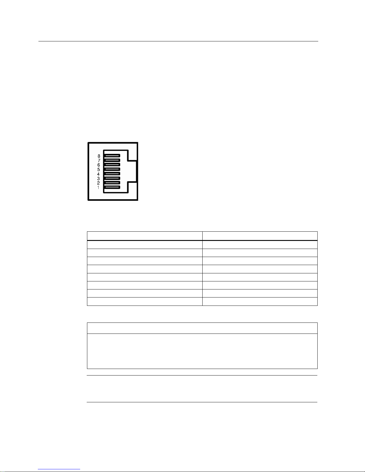
SCALANCE X204RNA TP interfaces
Connector pinout
On the SCALANCE X204RNA, the TP interfaces are implemented as RJ-45 jacks with the
MDI-X assignment (Medium Dependent Interface Autocrossover) of a network component.
Figure 4-2 RJ-45 jack
Table 4- 3 Pin assignment
Pin number Assignment
Pin 8 n. c.
Pin 7 n. c.
Pin 6 TDPin 5 n. c.
Pin 4 n. c.
Pin 3 TD+
Pin 2 RDPin 1 RD+
NOTICE
TP cords or TP-XP cords with a maximum length of 10 m can be connected to the RJ-45
TP port.
With the IE FC cables and IE FC RJ-45 plug 180, an overall cable length of up to 100 m is
permitted between two devices depending on the cable type.

Product characteristics
4.4 SCALANCE X204RNA
SCALANCE X204RNA SCALANCE X204RNA EEC (PRP)
20 Operating Instructions, , C79000-G8976-C294-03
Note
The interfaces of the SCALANCE X204RNA meet the requirements for environment B
according to IEEE 802.3, section 33.4.1.1.
Autonegotiation
Autonegotiation means the automatic detection of the functionality of the port at the opposite
end. Using autonegotiation, repeaters or end devices can detect the functionality available at
the port of a partner device allowing automatic configuration of different types of device. With
autonegotiation, two components connected to a link segment can exchange parameters
and set themselves to match the supported communication functionality.
Note
The SCALANCE X204RNA operates permanently in autonegotiation mode and can
therefore be connected to other devices that either also use the autonegotiation mode or the
100 Mbps mode FD (full duplex).
Note
The SCALANCE X204RNA is a plug-and-play device that does not require settings to be
made for commissioning.
MDI / MDIX autocrossover function
The advantage of the MDI / MDIX autocrossover function is that straight-through cables can
be used throughout and external Ethernet crossover cables are unnecessary. This prevents
malfunctions resulting from mismatching send and receive wires. This makes installation
much easier for the user.
The SCALANCE X204RNA supports the MDI / MDIX autocrossover function.
Note
Please note that the direct connection of two ports on the switch or accidental connection
over several switches causes an illegal loop. Such a loop can lead to network overload and
network failures.
Transmission speed
The transmission speed of the Fast Ethernet ports is 100 Mbps full duplex.
Product characteristics
4.5 SCALANCE X204RNA EEC
SCALANCE X204RNA SCALANCE X204RNA EEC (PRP)
Operating Instructions, , C79000-G8976-C294-03
21
4.5 SCALANCE X204RNA EEC
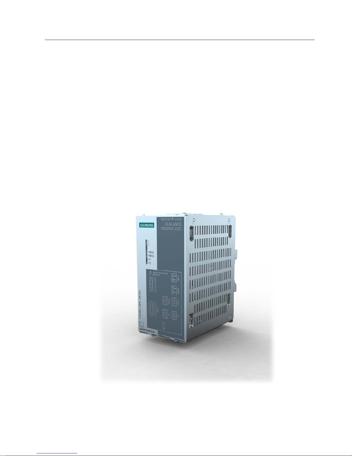
4.5.1 SCALANCE X204RNA EEC product characteristics
SCALANCE X204RNA EEC product characteristics
Possible attachments
The SCALANCE X204RNA EEC has four RJ-45 jacks and two slots for SFP modules. The
SFP modules can be used as an alternative to the two RJ-45 jacks PRP A and PRP B and
are intended for the connection of the LAN A and LAN B networks. End devices or network
segments without PRP capability are connected to the RJ-45 jacks P1 and P2.
Figure 4-3 SCALANCE X204RNA EEC
Product characteristics
4.5 SCALANCE X204RNA EEC
SCALANCE X204RNA SCALANCE X204RNA EEC (PRP)
22 Operating Instructions, , C79000-G8976-C294-03
4.5.2 SCALANCE X204RNA EEC TP interfaces
SCALANCE X204RNA EEC TP interfaces
Connector pinout
On the SCALANCE X204RNA EEC, the TP interfaces are implemented as RJ-45 jacks with
the MDI-X assignment (Medium Dependent Interface Autocrossover) of a network
component.
Figure 4-4 RJ-45 jack
Table 4- 4 Pin assignment
Pin number Assignment
Pin 8 n. c.
Pin 7 n. c.
Pin 6 TDPin 5 n. c.
Pin 4 n. c.
Pin 3 TD+
Pin 2 RDPin 1 RD+
NOTICE
TP cords or TP-XP cords with a maximum length of 10 m can be connected to the RJ-45
TP port.
With the IE FC cables and IE FC RJ-45 plug 180, an overall cable length of up to 100 m is
permitted between two devices depending on the cable type.
Note
The interfaces of the SCALANCE X204RNA EEC meet the requirements for environment B
according to IEEE 802.3, section 33.4.1.1.

Product characteristics
4.5 SCALANCE X204RNA EEC
SCALANCE X204RNA SCALANCE X204RNA EEC (PRP)
Operating Instructions, , C79000-G8976-C294-03
23
Autonegotiation
Autonegotiation means the automatic detection of the functionality of the port at the opposite
end. Using autonegotiation, repeaters or end devices can detect the functionality available at
the port of a partner device allowing automatic configuration of different types of device. With
autonegotiation, two components connected to a link segment can exchange parameters
and set themselves to match the supported communication functionality.
Note
The SCALANCE X204RNA EEC operates permanently in autonegotiation mode and can
therefore be connected to other devices that either also use the autonegotiation mode or the
100 Mbps mode FD (full duplex).
Note
The SCALANCE X204RNA EEC is a plug-and-play device that does not require settings to
be made for commissioning.
MDI / MDIX autocrossover function
The advantage of the MDI / MDIX autocrossover function is that straight-through cables can
be used throughout and external Ethernet crossover cables are unnecessary. This prevents
malfunctions resulting from mismatching send and receive wires. This makes installation
much easier for the user.
The SCALANCE X204RNA EEC supports the MDI / MDIX autocrossover function.
Note
Please note that the direct connection of two ports on the switch or accidental connection
over several switches causes an illegal loop. Such a loop can lead to network overload and
network failures.
Transmission speed
The transmission speed of the Fast Ethernet ports is 100 Mbps full duplex.
4.5.3 SCALANCE X204RNA EEC SFP interface
SCALANCE X204RNA EEC SFP interface
The SFF slots are used to insert suitable SFP modules.
Here the use of transceivers with an optical interface is particularly practical.

Product characteristics
4.5 SCALANCE X204RNA EEC
SCALANCE X204RNA SCALANCE X204RNA EEC (PRP)
24 Operating Instructions, , C79000-G8976-C294-03
Transmission medium and range
Table 4- 5 SFP transceiver - overview
SFP transceiver SFP991-1 SFP991-1LD SFP991-1LH+
Transmission medium
- Wavelength
- Core diameter
- Outer diameter
Multimode FO cable
1310 nm
50 or 62.5 µm
125 µm
Monomode FO cable
1310 nm
9 µm
125 µm
Monomode FO cable
1310 nm
9 µm
125 µm
Maximum range 3 km 26 km 70 km
Order number 6GK5991-1AD00-8AA0 6GK5991-1AF00-8AA0 6GK5991-1AE00-8AA0
Connectors
Electrical connection: SFF slot
Optical connection: Duplex LC connector
Transmission speed
The transmission speed of the optical Fast Ethernet ports is 100 Mbps.
Transmission technique
The transmission mode for 100Base-FX is specified in the IEEE 802.3 standard.

Product characteristics
4.6 C-PLUG
SCALANCE X204RNA SCALANCE X204RNA EEC (PRP)
Operating Instructions, , C79000-G8976-C294-03
25
4.6 C-PLUG
CPLUG (configuration plug)
Area of application
The C-PLUG is an exchangeable medium for storage of the configuration and project
engineering data of the basic device. This means that the configuration data remains
available if the basic device is replaced.
How it works
Power is supplied by the basic device. The C-PLUG retains all data permanently when the
power is turned off.
If an empty C-PLUG (factory settings) is inserted, all configuration data of the SCALANCE X200RNA is saved to it when the device starts up. Changes to the configuration during
operation are also saved on the C-PLUG without any operator intervention being necessary.
A basic device with an inserted C-PLUG automatically uses the configuration data of the CPLUG when it starts up. This is, however, only possible when the data was written by a
compatible device type.
This allows fast and simple replacement of the basic device. If a device needs to be
replaced, the C-PLUG is simply taken from the failed component and inserted in the
replacement device. The first time it is started up, the replacement device has the same
configuration as the failed device except for the MAC address set by the vendor.
Compatible devices
As a general rule, the data on the C-PLUG is only compatible with devices having an
identical order number and the same device name.
Over and above this, the data of the SCALANCE X204RNA and the SCALANCE X204RNA
is compatible.
Using a previously written C-PLUG
If you want to insert a C-PLUG that has already been used and has been written to in a
SCALANCE X-200RNA with a different configuration, the existing C-PLUG data must first be
deleted.
Note
An IE Switch X-200 normally starts up with the configuration of the C-PLUG, assuming this
was written to by a compatible device type.

Product characteristics
4.6 C-PLUG
SCALANCE X204RNA SCALANCE X204RNA EEC (PRP)
26 Operating Instructions, , C79000-G8976-C294-03
Diagnostics
Inserting a C-PLUG that does not contain the configuration of a compatible device type or
general malfunctions of the C-PLUG are signaled by the diagnostics mechanisms of the
SCALANCE X-200RNA (LEDs, SNMP, WBM, etc.).
Inserting in the C-PLUG slot
The C-PLUG is not supplied with the SCALANCE X-200RNA. It is available as an optional
accessory.
The slot for the C-PLUG is located as follows:
●With a SCALANCE X204RNA on the front of the device
●With the SCALANCE X204RNA EEC on the top of the device
Refer to Figure 4-6 Position of the C-PLUG and SET button (Page 28)
To inse
rt the C-PLUG, remove the protective cover. The C-PLUG is inserted in the slot.
The protective cover must then be closed correctly.
NOTICE
The C-PLUG may only be inserted or removed when the power is off!
Removing the C-PLUG
It is only necessary to remove the C-PLUG if a fault occurs on the SCALANCE X-200RNA.
The C-PLUG can be removed from the slot using flat pliers, tweezers, or a small screwdriver.
See also
SET button (Page 27)
Product characteristics
4.7 SET button
SCALANCE X204RNA SCALANCE X204RNA EEC (PRP)
Operating Instructions, , C79000-G8976-C294-03
27
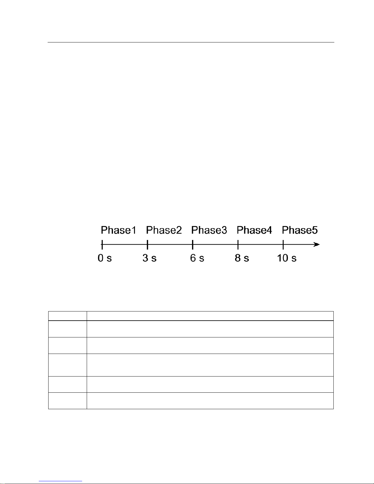
4.7 SET button
SET button
Button function
You can change various device settings with the button. Modified settings are retained after
device power off/on.
The SELECT / SET button is used to switch over the display mode and to make other
settings. After turning on the SCALANCE X-200RNA, it is in the display mode.
The button has three functions:
● Triggering a device restart
● Reset to the factory defaults All settings made are overwritten by the factory defaults.
● Define the fault mask and the display at the LEDs. The current states of all ports and the
states of the power supplies L1 and L2 are included in the fault mask. The previous fault
mask is then overwritten.
Different settings are made depending on how long you hold down the button:
Figure 4-5 The five button phases
Time the button is pressed in seconds
Table 4- 6 Button phases
Phase Description
1 The currently set fault mask is displayed. If no fault mask has been set, all ports flash one after the other.
If you release the button in phase 1, this has no effect.
2 The LEDs of the ports at which there is currently a link flash at 2.5 Hz.
If you release the button in phase 2, this has no effect.
3 The LEDs of the ports at which there is currently a link and the LEDs of the connected power supply are lit
permanently.
If you release the button in phase 3, the fault mask corresponding to the lit LEDs is adopted.
4 All port LEDs flash at 2.5 Hz.
Releasing the button during this phase brings about a device restart (soft reset)
5 All port LEDs flash alternately yellow/green at 2.5 Hz.
The device is reset to the factory defaults.
Product characteristics
4.7 SET button
SCALANCE X204RNA SCALANCE X204RNA EEC (PRP)
28 Operating Instructions, , C79000-G8976-C294-03
Note
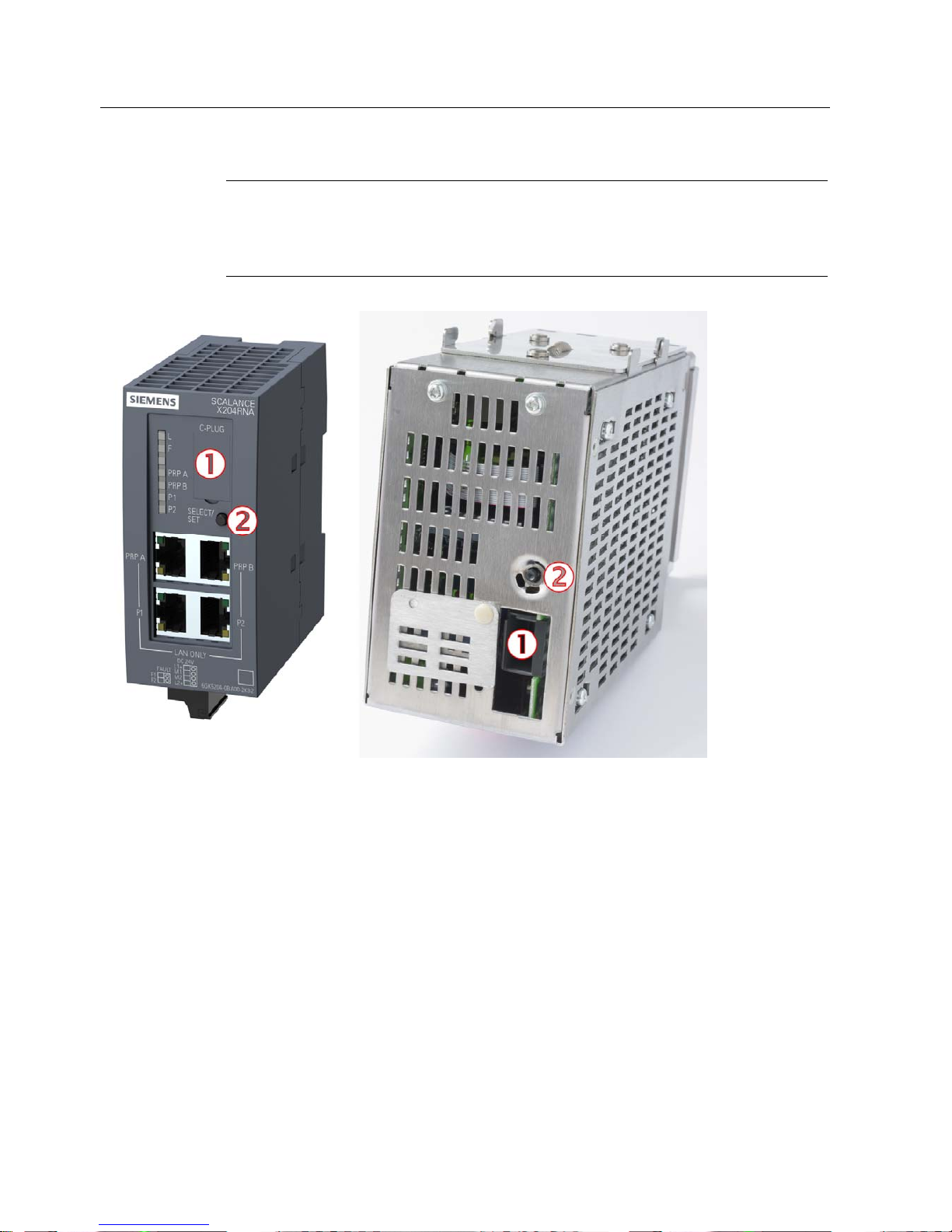
On the SCALANCE X204RNA, the button is located below the C-PLUG compartment.
On the SCALANCE X204RNA EEC, the button is on the top of the device in a recess next to
the C-PLUG compartment.
① C-PLUG
② SET button
Figure 4-6 Position of the C-PLUG and SET button

Product characteristics
4.8 Displays
SCALANCE X204RNA SCALANCE X204RNA EEC (PRP)
Operating Instructions, , C79000-G8976-C294-03
29
4.8 Displays
4.8.1 Fault indicator (yellow/red LED)
Fault indicator (yellow/red LED)
If the LED is lit red, a SCALANCE X-200RNA has detected an error/fault.
At the same time, the signaling contact opens assuming that the response of the signaling
contact has not been configured differently.
The LED signals that the SCALANCE X-200RNA can adopt the following statuses:
Device type SCALANCE LED lit red LED lit yellow LED not lit
X204RNA 1, 2, 3, 4, 5 6 7
X204RNA EEC 1, 3, 4, 5 6 7
1. Link down event on a monitored port.
2. Failure of one of the two redundant power supplies.
3. C-PLUG error
4. Device startup, the LED is lit for approx. 20 seconds.
5. Internal error.
6. A redundancy error was detected.
7. No problem has been detected by the SCALANCE X-200RNA.
4.8.2 Power display
Power display
The LEDs signal the following statuses of the SCALANCE X-200RNA.
The status of the power supply is indicated by a green LED:
Device type SCALANCE LED lit green LED lit yellow LED not lit
X204RNA 1 2 3
X204RNA EEC 4 - 5
1. Both L power supplies are connected (redundant supply).
2. One L power supply is connected (non-redundant supply).
3. Power supply L1 and L2 are not connected or supply voltages are <14 V.

Product characteristics
4.8 Displays
SCALANCE X204RNA SCALANCE X204RNA EEC (PRP)
30 Operating Instructions, , C79000-G8976-C294-03
4. Power supply L is connected
5. Power supply L is not connected or the supply voltage is too low.
4.8.3 Port status indication
Port status indicator (green/yellow LEDs)
The LEDs signal the following port statuses of the SCALANCE X-200RNA.
The status of interfaces is indicated by two-color LEDs:
Device type SCALANCE
Number of LEDs
LED lit green LED lit yellow LED flashes yellow
2 port LEDs 1 2, 3 4 X204RNA
2 PRP port LEDs 1 2, 3 4
2 port LEDs 1 2, 3 4 X204RNA EEX
2 PRP port LEDs 1 2, 3 4
1. TP link exists, no data reception.
2. TP link, data received at TP port.
3. Device startup, the LED is lit for approx. 6 seconds.
4. Setting or display of the fault mask.
4.8.4 LED displays during startup
LED displays during startup
When a device starts up, the following displays light up in the order shown:
1. Power LEDs (green) light up immediately after turning on the power.
2. Port LEDs go off, the red error LED is lit for approx. 10 seconds.
3. Following startup, the correct link status is indicated by the port LEDs after approximately
5 seconds.
4. The SCALANCE X-200RNA is now ready for operation.
 Loading...