

Siemens Scalance X204-2 Multimode, Scalance X204-2LD Single Mode Installation Instructions Manual
Installation Instruct ions
P1
P2
P3
P4
P5
P6
IN
OUT
IN
OUT
FAULT
F1
F2
L1+
M1
L2+
M2
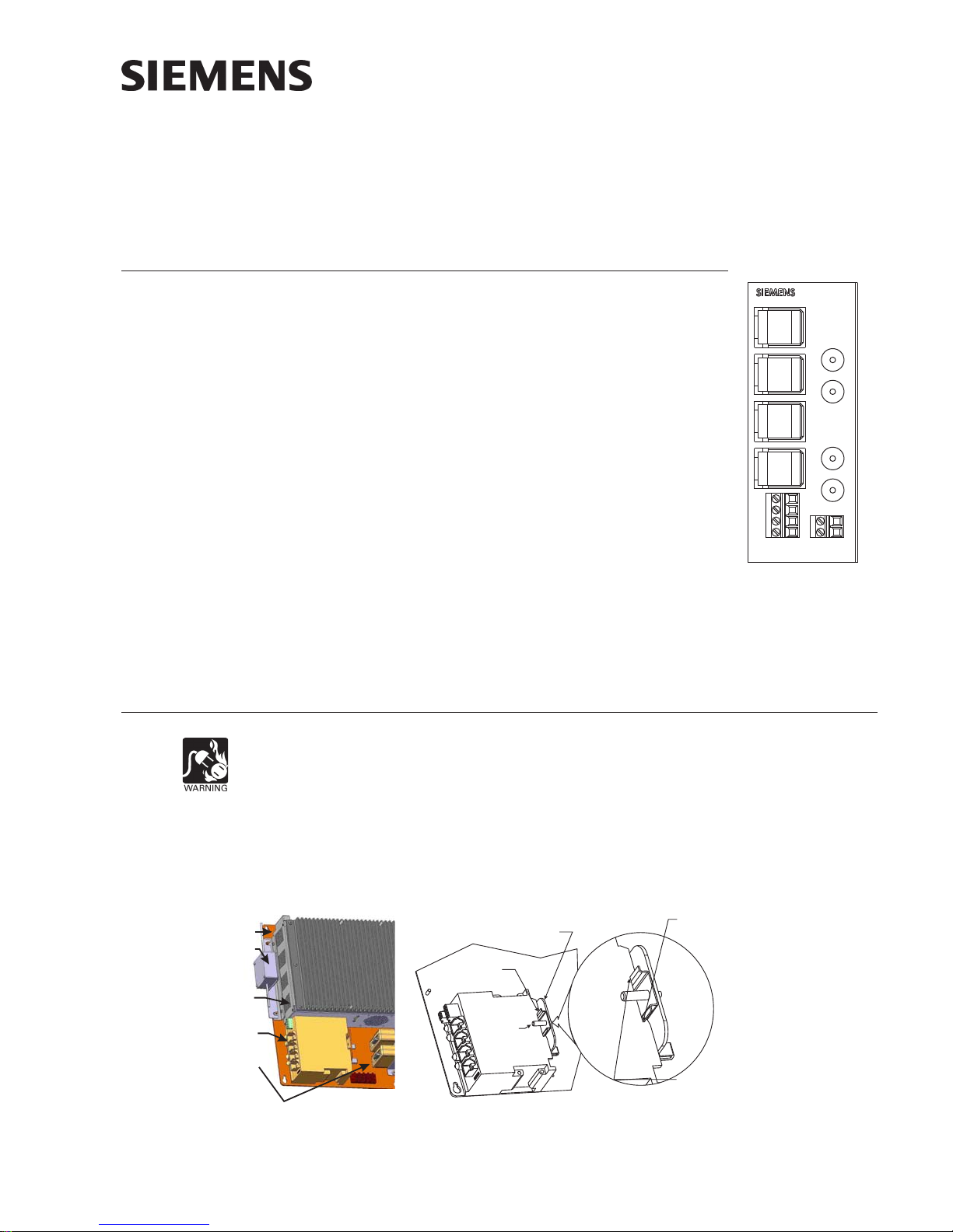
Model Scalance X204-2 Multimode and X204-2LD Single Mode
Ethernet Fiber Switch
Fiber Switch Ethernet Connections
INTRODUCTION The Model Scalance X204-2 Multimode and X204--2LD Single
Mode Ethernet Fiber Switch (as shown in Figure 1) from
Siemens Building Technologies, Inc. is used to maintain a Style
7 ring or Style 4 (Class B) wiring for communications between
all buildings and Siemens Building Management Systems (Fire
Command Centers within a FVNET campus, NCC, Desigo CC,
Cerberus DMS). Both Style 7 and Style 4 perform all required
monitoring of the health of the network. Style 7 wiring will
automatically ‘heal’ the ring when a break or other failure is
encountered. The failure is reported via SNMP (Simple
Network Management Protocol).
OUT
The fiber switch obtains its power from a 24V UL Listed for
Fire Application, Power Limited - Regulated Power Supply. It
provides connectors for the fiber cable and four RJ45
100BaseT network connections.
In Style 7, the fiber switch that is connected to the primary
NCC is designated as the ring master. There is no difference
in installation, configuration, and operation of single mode or
multimode fiber optic switches except the type of fiber used.
INSTALLATION
Remove all system power before installation, first battery then AC. (To power up,
connect the AC first, then the battery.)
Mounting on VNT-MP The fiber switch mounts on a bracket in the lower left corner of the VNT-MP mount-
ing plate as shown in Figure 2. To mount the fiber switch on the bracket, place the
bottom edge of the fiber switch cutout on the bottom edge of the rail between the
VNT-MP and the standoff and then snap the top edge of the fiber switch cutout on to
the top edge of the rail. Refer to Figure 3 for the mounting detail.
VNT-MP
VNT-PS
P/N 315-050537-3
VNT
FIBER
SWITCH
XND
Figure 2
Fiber Switch Mounting on VNT-MP
BRACKET FOR
MOUNTING
FIBER SWITCH
RAIL FOR
MOUNTING
FIBER SWITCH
STANDOFF
TO KEEP
FIBER
SWITCH
IN PLACE
Figure 3
Fiber Switch Mounting Detail
Building Building
Building
Building Building
L2+
Figure 1
Scalance X204-2/
X204-2LD Ethernet
Multimode
Fiber Switch
1. PLACE BOTTOM EDGE OF
FIBER SWITCH GROOVE ON
BOTTOM EDGE OF RAIL.
2. SNAP TOP EDGE OF
FIBER SWITCH GROOVE
ON TO TOP EDGE OF RAIL.
Siemens Siemens
Siemens
Siemens Siemens
TT
ecec
hnologies Dihnologies Di
T
ec
hnologies Di
TT
ecec
hnologies Dihnologies Di
IndustryIndustry
Industry
IndustryIndustry
,,
Inc. Inc.
,
Inc.
,,
Inc. Inc.
visionvision
vision
visionvision
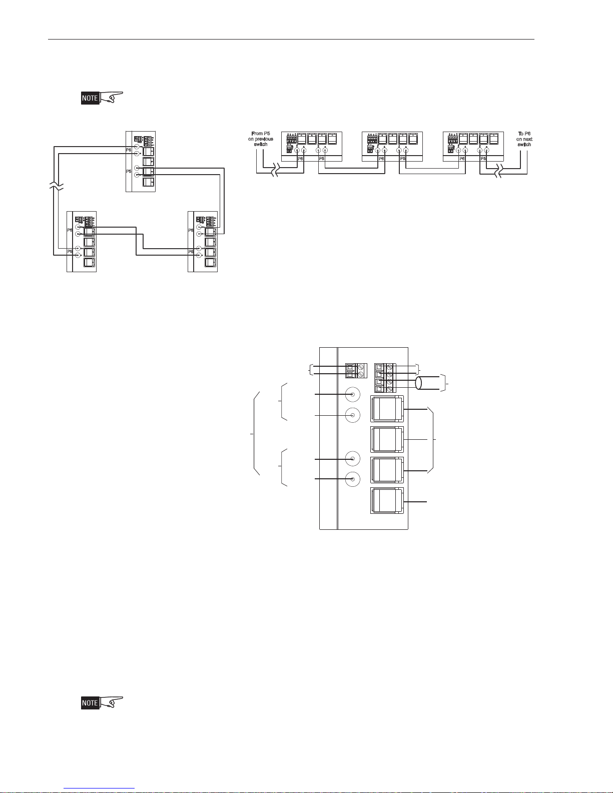
WIRING Figure 4 shows the fiber switch module block wiring diagrams for both Style 7 (Class
P1
P2
P3
P4
P5
P6
IN
OUT
IN
OUT
FAULT
F1
F2
L1+
M1
L2+
M2
NEXT
SWITCH
TO P5 IN
TO P5 OUT
FIBER
FROM P6 IN
FROM P6 OUT
FIBER
OPTIONAL CONNECTIONS
TO
ONE OR MORE:
1. ADDITIONAL VNT
2.
NCC
3.
SMOKE CONTROL
CATEGORY 5
RJ45 CABLE
LESS THAN
20 FT. IN CONDUIT
PREVIOUS
SWITCH
RJ45
CATEGORY 5 RJ45 CABLE
LESS THAN
20 FT. IN CONDUIT
BLK
RED
POWER
LIMITED
DO NOT USE
DO NOT USE
MAXIMUM
ATTENUATION
6dB
NOTE:
FOR
STYLE 4 (CLASS B)
OMIT CONNECTION
BETWEEN
FIRST AND
LAST FIBER
SWITCH.
X) and Style 4 (Class B). Figure 5 shows the wiring for the Fiber Switch connections
in Style 7 and Style 4 (Class B).
F2
L2+
F1
M2
FAULT
M1
L1+
OUT
P6
P4
IN
P3
OUT
P2
P5
IN
P1
SIEMENS
F2
L2+
F1
M2
FAULT
M1
L1+
OUT
P6
P4
IN
P3
OUT
P2
P5
IN
P1
SIEMENS
Style 7 Block Wir i ng Di a gr am
Figure 4
Style 7 and Style 4 (Class B) Block Wiring of Fiber Switch Module
All connectAll connect
All connect
All connectAll connect
F2
L2+
F1
M2
FAULT
M1
L1+
OUT
P6
P4
IN
P3
OUT
P2
P5
IN
P1
SIEMENS
NOTE:
FOR STYLE 4 (CLASS B)
OMIT CONNECTION
BETWEEN FIRST AND
LAST FIBER SWITCH.
ions are supervised and powerions are supervised and power
ions are supervised and power
ions are supervised and powerions are supervised and power
+
+
From P5
on previous
switch
2
4
1
2
L
M1L
M
2
F1F
T
T
U
L
O
U
A
F
P6
1
S
P
P2P3P
N
E
M
E
I
S
T
U
N
N
I
I
O
P5
Style 4 (Class B) Block Wiring Diagram
DO NOT USE
TO P5 IN
NEXT
SWITCH
TO P5 OUT
MAXIMUM
ATTENUATION
6dB
PREVIOUS
FROM P6 IN
SWITCH
FROM P6 OUT
limit limit
limit
limit limit
+
2
2
+
2
1
L
M1L
M
F1F
T
L
U
A
F
ed unless sted unless st
ed unless st
ed unless sted unless st
2
4
T
U
O
P6
1
S
P
P
P3P
N
E
M
E
I
S
T
U
N
N
I
I
O
P5
DO NOT USE
atat
ed otherwise.ed otherwise.
at
ed otherwise.
atat
ed otherwise.ed otherwise.
+
+
2
1
4
2
L
M1L
M
2
F1F
T
T
U
L
N
I
O
U
A
F
P6
POWER
LIMITED
OPTIONAL CONNECTIONS
TO ONE OR MORE:
1. ADDITIONAL VNT
2. NCC
3. SMOKE CONTROL
CATEGORY 5 RJ45 CABLE
LESS THAN 20 FT.IN CONDUIT
1
2
S
To P 6
P
P
P3P
N
E
M
E
on next
I
S
T
U
N
I
O
P5
switch
Figure 5
Fiber Switch Style 7 and Style 4 (Class B) Wiring Connections
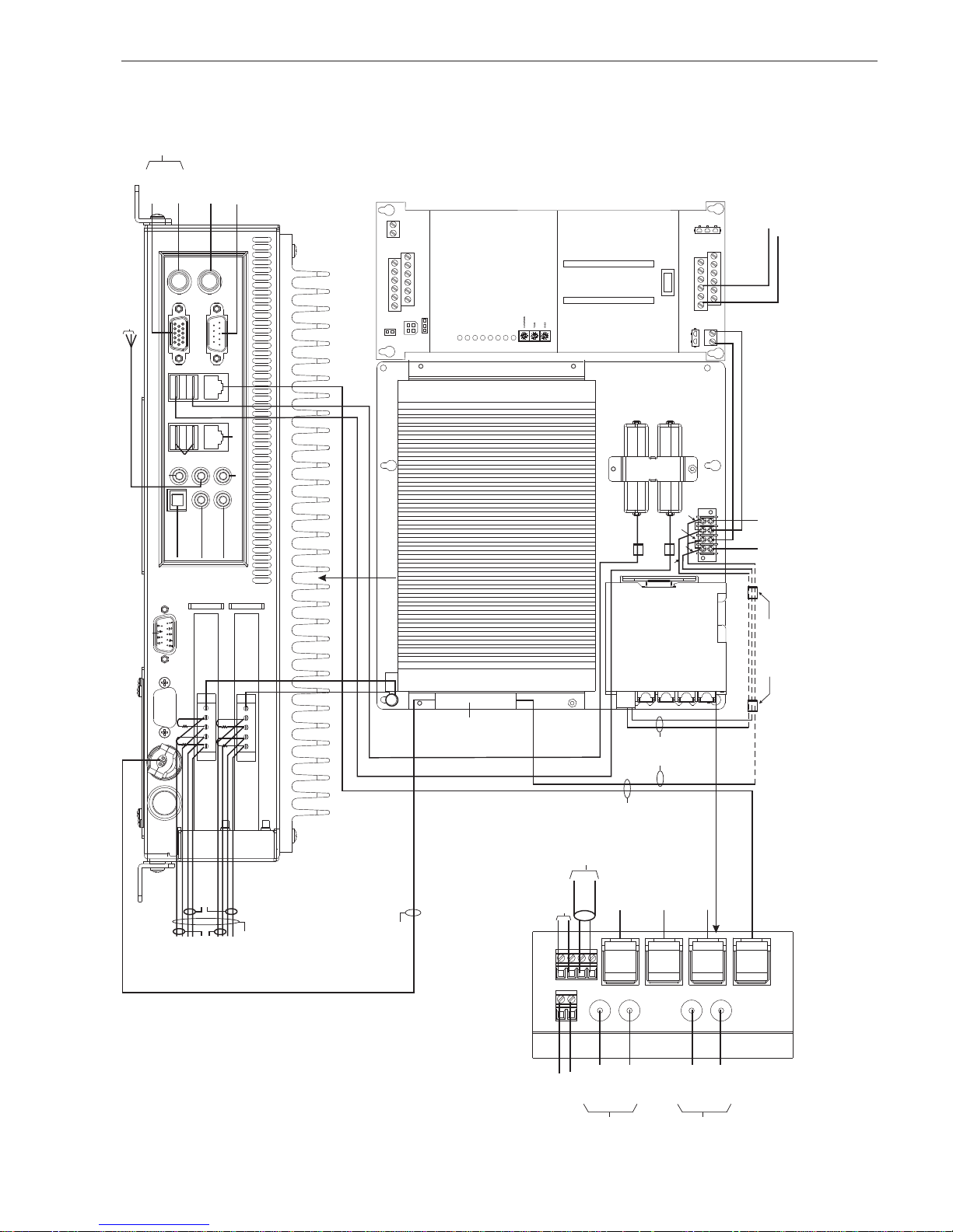
Refer to Figure 6 for the wiring of the fiber switch in a VNT-Building configuration.
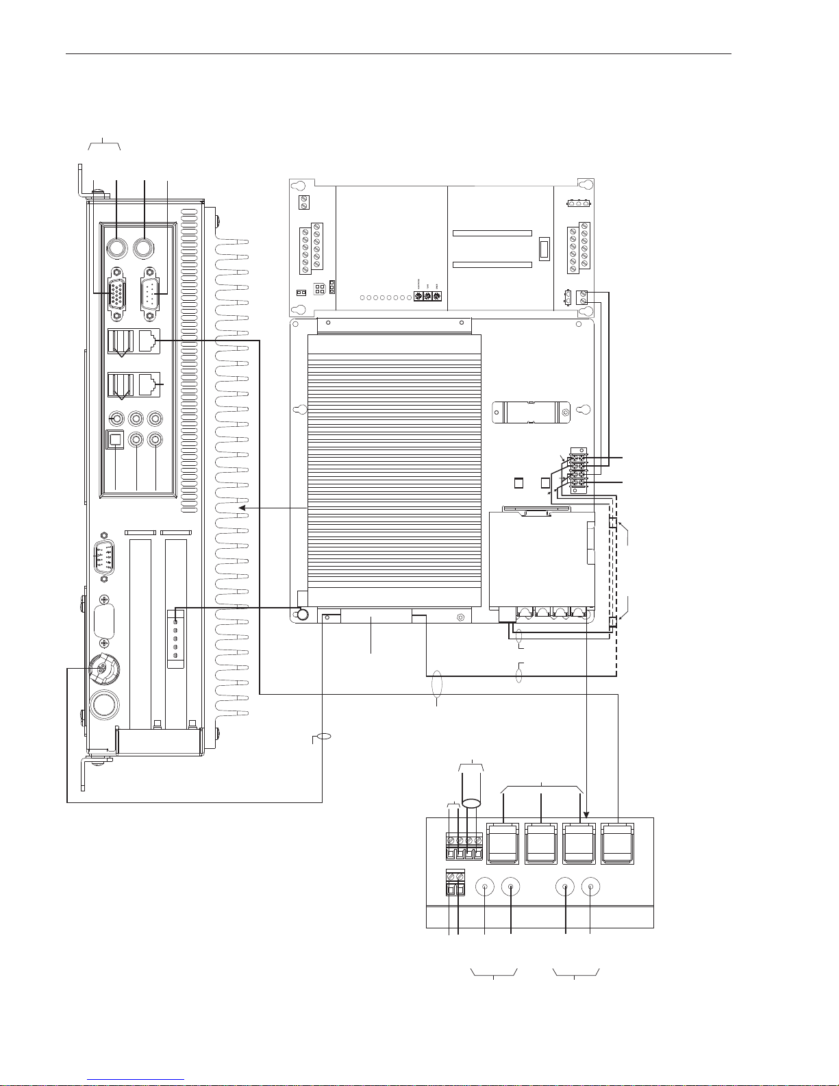
Figure 7 shows the wiring of the fiber switch in a VNT-FCC (Fire Command Center)
configuration. Refer to Figures 10 and 11 for the wiring of the fiber switch to PAD-3
and PAD-4 and Siemens Building Management System.
Fiber Connections Two fiber optic cables are required between each pair of fiber switch modules. Use a
Siemens Industry, Inc.
Building Technologies Division
high quality duplex fiber optic cable containing 62.5/125 or 50/125 multimode fiber or
g/125 for single mode fiber. Duplex fiber optic cable has two cables in a single
shield similar to electrical zip cord. Use ST style fiber connectors.
Please contPlease cont
Please cont
Please contPlease cont
the fiberthe fiber
the fiber
the fiberthe fiber
forfor
addit addit
for
addit
forfor
addit addit
act the fiberact the fiber
act the fiber
act the fiberact the fiber
..
R R
.
R
..
R R
ional informational informat
ional informat
ional informational informat
eferefer
to S to S
efer
to S
eferefer
to S to S
cable manufact cable manufact
cable manufact
cable manufact cable manufact
calance X-20calance X-20
calance X-20
calance X-20calance X-20
ion on fiberion on fiber
ion on fiber
ion on fiberion on fiber
0 Operat0 Operat
0 Operat
0 Operat0 Operat
opt opt
ic switcic switc
opt
ic switc
opt opt
ic switcic switc
SIEMENS
urerurer
reg reg
urer
urerurer
arding instructarding instruct
reg
arding instruct
reg reg
arding instructarding instruct
ing Instructing Instruct
ing Instruct
ing Instructing Instruct
heshes
hes
heshes
CATEGORY 5 RJ45 CABLE
LESS THAN 20 FT.IN CONDUIT
ions,ions,
C790 C790
ions,
C790
ions,ions,
C790 C790
ions forions for
ions for
ions forions for
00
0-G8970-G897
0
0-G897
0
0
0-G8970-G897
t t
erminaterminat
t
erminat
t t
erminaterminat
6-C284-05,6-C284-05,
6-C284-05,
6-C284-05,6-C284-05,
P/N 315-050537-32
inging
ing
inging
P1
P2
P3
P4
P5
P6
IN
OUT
IN
OUT
FAULT
F1
F2
L1+
M1
L2+
M2
*NEXT
SWITCH
TO P5 IN
TO P5 OUT
FIBER
FROM P6 IN
FROM P6 OUT
FIBER
*PREVIOUS
SWITCH
RJ45
VIDEO
DO NOT USE
DIAGNOSTIC
ONLY
DO NOT USE
DO NOT USE
DO NOT USE
DO NOT USE
DO NOT USE
KEYBOARD
DO
NOT
USE
USB
SIDE
USB
SIDE
OPTIONAL
OPTIONAL
TIE
WRAP
ADDITIONAL 24V
NON-POWER
LIMITED
+
_
L1+
M1
BLK
RED
BLK
RED
CATEGORY5 RJ45 CABLE
LESS THAN
20 FT.IN CONDUIT
BLK
RED
TO AIC, TERMINAL4 (+)
TO AIC, TERMINAL5 (-)
DO NOT USE
DO NOT USE
DO NOT USE
NON-POWER
LIMITED
SUPERVISED,
NON-POWER
LIMITED
DO NOT USE
DO NOT USE
DO NOT USE
TO AIC, TERMINAL1 (+)
TO AIC, TERMINAL2 (-)
AUDIO OUT CABLE P/N 555-150464 (GREEN)
+
_
+
_
BACK OF VNT
DO NOT USE
DO NOT USE
DO NOT USE
*WIRING SHOWN IS
STYLE
7 (CLASS A).
CAN ALSO
BE WIRED
STYLE
4 (CLASS B).
SUPERVISED,
NON-POWER
LIMITED
SECURE WITH TIE WRAP
TO
LANCES INSIDE
THE
ENCLOSURE
NOTE:
POWER
LIMITED
AND
NON-POWER
LIMITED
WIRING
MUST BE
SEPARATED
BY AMINIMUM
OF
1/4” SPACING.
NOTE:
POWER
LIMITED
AND
NON-POWER
LIMITED
WIRING
MUST BE
SEPARATED
BY AMINIMUM
OF
1/4” SPACING.
CONNECTING TO VNT-BUILDING
DIAGNOSTIC
ONLY
DO NOT USE
DO NOT USE
TO AIC, TERMINAL1 (+)
TO AIC, TERMINAL2 (-)
2
_
TB3
1
+
12
6
TB1
7
1
12
34
P5
P4
1
P10
RESET
PSC-12
POWER
GND FAULT
24V 12AFAIL
24V 4AFAIL
HNETFAIL
CAN FAIL
MODULE FAIL
HNET/CAN
BATTERY
N
H
GND
P12
18
24
ON
—
O
OFF
TB2
13
19
P9
_
2
+
_
1
TO AIC, TERMINAL5 (-)
TO AIC, TERMINAL4 (+)
TB4
+
NON-POWER
LIMITED
USB
NOTE:
POWER LIMITED
SIDE
TIE
WRAP
LIMITED
NON-POWER
SUPERVISED,
MUST BE
SEPARATED
LIMITED WIRING
AND NON-POWER
USB
SIDE
BY AMINIMUM
OF 1/4” SPACING.
ADDITIONAL 24V
SECURE WITH TIE WRAP
NON-POWER LIMITED
TO LANCES INSIDE
THE ENCLOSURE
DO
NOT
DO NOT USE
AUDIO OUT CABLE P/N 555-150464 (GREEN)
DO NOT USE
BACK OF VNT
DO NOT USE
DO NOT USE
USE
DO NOT USE
DO NOT USE
DO NOT USE
VNT
EARTH GROUND
EARTH GROUND
5
5
4
*
*
3
2
1
NCC-2F
(HNET)
4
3
*
2
1
*
(XNET)
NCC-2F
VNT-PS
PAIRA
SUPERVISED
POWER LIMITED
P/N 140-820350
EOLR 120 OHMS, 1/2W,5%
*
PAIRB
SUPERVISED
POWER LIMITED
OMIT FOR STYLE 4
NOTE:
POWER LIMITED
MUST BE
SEPARATED
LIMITED WIRING
AND NON-POWER
BY AMINIMUM
OF 1/4” SPACING.
Siemens Industry, Inc.
Building Technologies Division
SUPERVISED,
NON-POWER LIMITED
DO NOT USE
DO NOT USE
DO NOT USE
DO NOT USE
TO P5 IN
TO P5 OUT
*NEXT
SWITCH
STYLE 7 (CLASS A).
*WIRING SHOWN IS
DO NOT USE
STYLE 4 (CLASS B).
CAN ALSO BE WIRED
FROM P6 IN
*PREVIOUS
DO NOT USE
SWITCH
CATEGORY5 RJ45 CABLE
LESS THAN 20 FT.IN CONDUIT
SIEMENS
FROM P6 OUT
Figure 6
Fiber Switch Connection Diagram for VNT-Building
P/N 315-050537-33
P1
P2
P3
P4
P5
P6
IN
OUT
IN
OUT
FAULT
F1
F2
L1+
M1
L2+
M2
NEXT
SWITCH
TO P5 IN
TO P5 OUT
FIBER
FROM P6 IN
FROM P6 OUT
FIBER
OPTIONAL CONNECTIONS
TO
ONE OR MORE:
1. ADDITIONAL VNT
2.
NCC3.SMOKE CONTROL
CATEGORY5
RJ45 CABLE
LESS THAN
20 FT.IN CONDUIT
PREVIOUS
SWITCH
RJ45
VIDEO
DO NOT USE
DIAGNOSTIC
ONLY
DO NOT USE
DO NOT USE
DO NOT USE
DO NOT USE
DO NOT USE
KEYBOARD
DO
NOT
USE
SUPERVISED,
NON-POWER
LIMITED
+
_
L1+
M1
BLK
RED
BLK
RED
CATEGORY5 RJ45 CABLE
LESS THAN
20 FT.IN CONDUIT
BLK
RED
DO NOT USE
NON-POWER
LIMITED
VNT
DO
NOT
USE
DO NOT USE
+
_
ADDITIONAL 24V
NON-POWER
LIMITED
BACK OF VNT
DO NOT USE
DO NOT USE
DO NOT USE
*WIRING SHOWN IS
STYLE
7 (CLASS A).
CAN ALSO
BE WIRED
STYLE
4 (CLASS B).
SECURE WITH TIE WRAP
TO
LANCES INSIDE
THE
ENCLOSURE
SUPERVISED,
NON-POWER
LIMITED
NOTE:
POWER
LIMITED
AND
NON-POWER
LIMITED
WIRING
MUST BE
SEPARATED
BY AMINIMUM
OF
1/4” SPACING.
CONNECTING TO VNT-FCC (FIRE COMMAND CENTER)
DIAGNOSTIC
ONLY
KEYBOARD
DO NOT USE
DO NOT USE
_
DO
USE
NOT
DO
NOT
DO NOT USE
DO NOT USE
USE
+
TB1
P5
2
TB3
1
12
6
BATTERY
7
1
12
34
P4
1
P10
RESET
PSC-12
POWER
GND FAULT
24V 12AFAIL
24V 4AFAIL
HNETFAIL
CAN FAIL
MODULE FAIL
HNET/CAN
N
H
GND
P12
18
24
ON
—
O
OFF
TB2
13
19
P9
_
2
+
_
1
TB4
+
DO NOT USE
DO NOT USE
DO NOT USE
ADDITIONAL 24V
NON-POWER LIMITED
BACK OF VNT
DO NOT USE
EARTH GROUND
5
4
3
2
1
VNT-PS
(HNET)
NCC-2F
SUPERVISED,
NON-POWER LIMITED
NOTE:
POWER LIMITED
MUST BE
SEPARATED
LIMITED WIRING
AND NON-POWER
BY AMINIMUM
OF 1/4” SPACING.
DO NOT USE
NON-POWER
LIMITED
LIMITED
NON-POWER
SUPERVISED,
OPTIONAL CONNECTIONS
TO ONE OR MORE:
1. ADDITIONAL VNT
2. NCC
3. SMOKE CONTROL
CATEGORY5 RJ45 CABLE
LESS THAN 20 FT.IN CONDUIT
SECURE WITH TIE WRAP
CATEGORY5 RJ45 CABLE
TO LANCES INSIDE
LESS THAN 20 FT.IN CONDUIT
THE ENCLOSURE
SIEMENS
Siemens Industry, Inc.
Building Technologies Division
DO NOT USE
DO NOT USE
TO P5 IN
FIBER
TO P5 OUT
NEXT
SWITCH
FROM P6 IN
FROM P6 OUT
Figure 7
Fiber Switch Connection Diagram for VNT-FCC (Fire Command Center)
CAN ALSO BE WIRED
SWITCH
STYLE 4 (CLASS B).
PREVIOUS
STYLE 7 (CLASS A).
*WIRING SHOWN IS
P/N 315-050537-34
ELECTRICAL RATINGS
D
All connectAll connect
All connect
All connectAll connect
fiberfiber
fiber
fiberfiber
099082) or099082) or
099082) or
099082) or099082) or
ions are supervised and powerions are supervised and power
ions are supervised and power
ions are supervised and powerions are supervised and power
switc switc
h mah ma
switc
switc switc
y be connecty be connect
h ma
y be connect
h mah ma
y be connecty be connect
P P
AD-4 (P/N 31AD-4 (P/N 31
P
AD-4 (P/N 31
P
P
AD-4 (P/N 31AD-4 (P/N 31
5-050215-05021
5-05021
5-050215-05021
ed to a PSC-1ed to a PSC-1
ed to a PSC-1
ed to a PSC-1ed to a PSC-1
7) for7) for
power power
7) for
power
7) for7) for
power power
Input Voltage: Regulated 24VDC
Input Current: 265mA @ 24VDC
Connecting to Siemens Power Supply and Building Management System
Remove all system power before installation, first battery and then AC.
power up, connect the AC first and then the battery.) Figures 8 and 9 show the
general layout of the PAD-3 and PAD-4 main board, respectively. This section also
provides specific wiring details to the Siemens UL approved power supply. Consult
your control unit manual for specific wiring information on the control unit being
used.
limit limit
ed unless sted unless st
limit
ed unless st
limit limit
ed unless sted unless st
2 (P/N 312 (P/N 31
2 (P/N 31
2 (P/N 312 (P/N 31
..
.
..
5-033060),5-033060),
5-033060),
5-033060),5-033060),
atat
ed otherwise.ed otherwise.
at
ed otherwise.
atat
ed otherwise.ed otherwise.
or or
P P
AD-3 (P/N 31AD-3 (P/N 31
or
P
AD-3 (P/N 31
or or
P P
AD-3 (P/N 31AD-3 (P/N 31
TheThe
The
TheThe
(To
5-5-
5-
5-5-
Siemens Industry, Inc.
Building Technologies Division
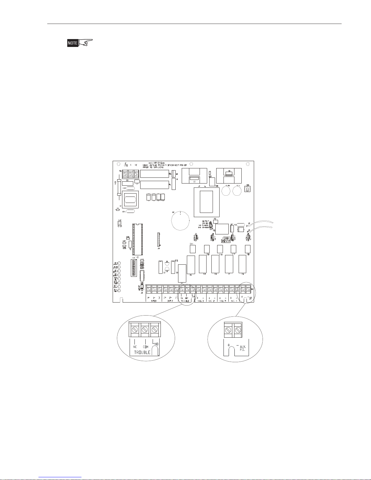
Figure 8
PAD-3-MB Layout
TB2
COMMON TROUBLE
RELAY CONTACT
AUXILIARY POWER OUTPUT
3A MAX., 18-28 VDC
SUPERVISED, POWER LIMITE
P/N 315-050537-35
B+
B-
J16
170W 10A
300W 20A
SERVICE
PORT
J6
DS8
P2
J3
1
J1*
J10
PWR
JP7
DS6
DS2
DS3
DS4
S2
RESET
DS1
OUT2
OUT3
OUT1
OUT4
10 9 8 7 6 5 4 3 2 1
P1
DS5
BUSY
BAT
AUX/PS
S1
ON
TB10
J9
J2**
PSSI GND +24V
BRNOUT
DS11
DS7
TB11
1-2+1
J14
J12
1
TB12
NCCOM2- 2
J13
1
TB13 TB14 TB15
NC COM NO
NOT
USEDTROUBLE
COMMON TROUBLE
RELAY CONTACT
J11
1
1+
INPUT 1 INPUT 2
*J1 - Set Jumper J1 to 2-3 for normal operation
**J2 - Must be installed for Canadian installations. Must be removed for UL installations.
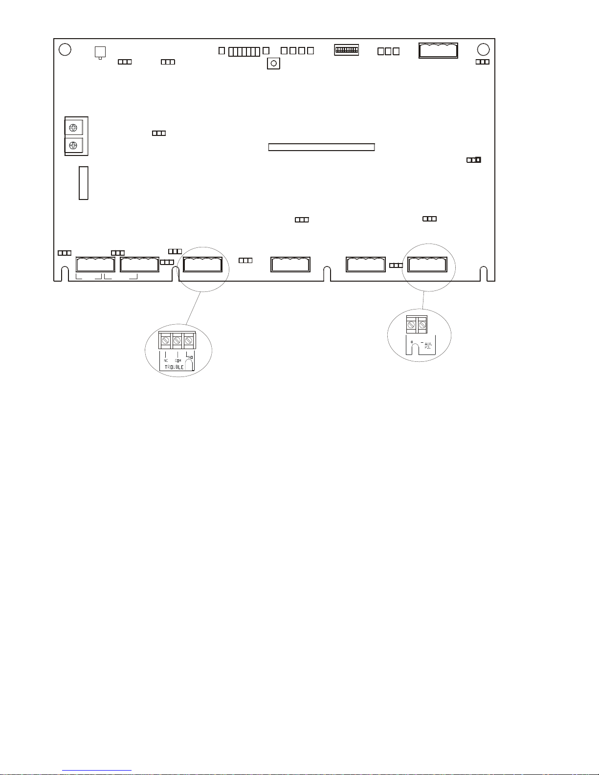
Figure 9
PAD-4-MB Layout
Auxiliary Power Supply Output
The auxiliary power supply output provides a 24VDC power source. It is supervised
for ground fault and short and is power limited. For applications where the battery
charger circuit charges batteries of 7.0 A.H. or less, or if the battery charger is disabled, this output is limited to 3.0 amps maximum. For batteries between 15 A.H.
and 7.0 A.H., this output is limited to 1.5 amps maximum.
J4
1 1
J5
_+_
+
NAC1B NAC2B (NAC1A)
1
_+_
+
NAC3B NAC4B (NAC2A)
J8
J7
TB16
_
+
AUX PWR SUPPLY
AUXILIARY POWER OUTPUT
3A MAX., 18-28 VDC
SUPERVISED, POWER LIMITED
Common Trouble Relay
The UL approved power supply has a built-in Form C trouble relay. The trouble relay
will de-energize under a trouble condition. A typical application of the trouble relay is
to connect the UL approved power supply normally closed (N.C.) contacts in series
with an EOL of a spare IDC or NAC or monitor input from a fire alarm control unit.
This will cause a trouble on the fire alarm control unit when the UL approved power
supply opens its trouble contacts. The common trouble relay will be de-energized
after selectable delay (60-180 minutes) if AC is low or lost.
Note: The N.C. contact is the relay contact that is closed when the PAD-4 has power
and there are no trouble conditions.
Siemens Industry, Inc.
Building Technologies Division
P/N 315-050537-36
R
T
S
E
H
R
E
N
T
B
T
2
I
E
3
-
D
P
A
T
E
H
R
E
N
T
E
T
E
H
R
E
N
E
T
S
E
M
E
N
S
Siemens Building
Management System
T
H
R
E
N
E
T
E
C
N
A
T
T
O
C
Y
T
(
S
H
N
W
O
0
D
V
3
C
,
R
E
A
2
@
A
R
U
O
B
L
E
R
E
L
D
L
S
A
R
T
A
M
O
N
N
I
S
N
P
O
W
E
F
R
O
T
S
I
I
V
E
V
R
I
S
E
U
S
N
U
P
N
O
I
N
)
T
I
D
O
C
Y
B
L
I
U
I
T
C
M
R
O
E
S
E
D
R
E
D
C
E
O
L
I
D
L
T
O
R
E
S
(
E
C
N
O
U
N
I
T
T
A
A
I
L
L
O
N
I
N
T
S
T
N
I
)
S
O
I
N
T
S
R
C
U
I
D
T
C
U
M
O
E
H
W
F
I
B
R
E
L
F
I
H
T
B
E
E
O
O
R
T
S
C
L
A
A
N
E
C
S
W
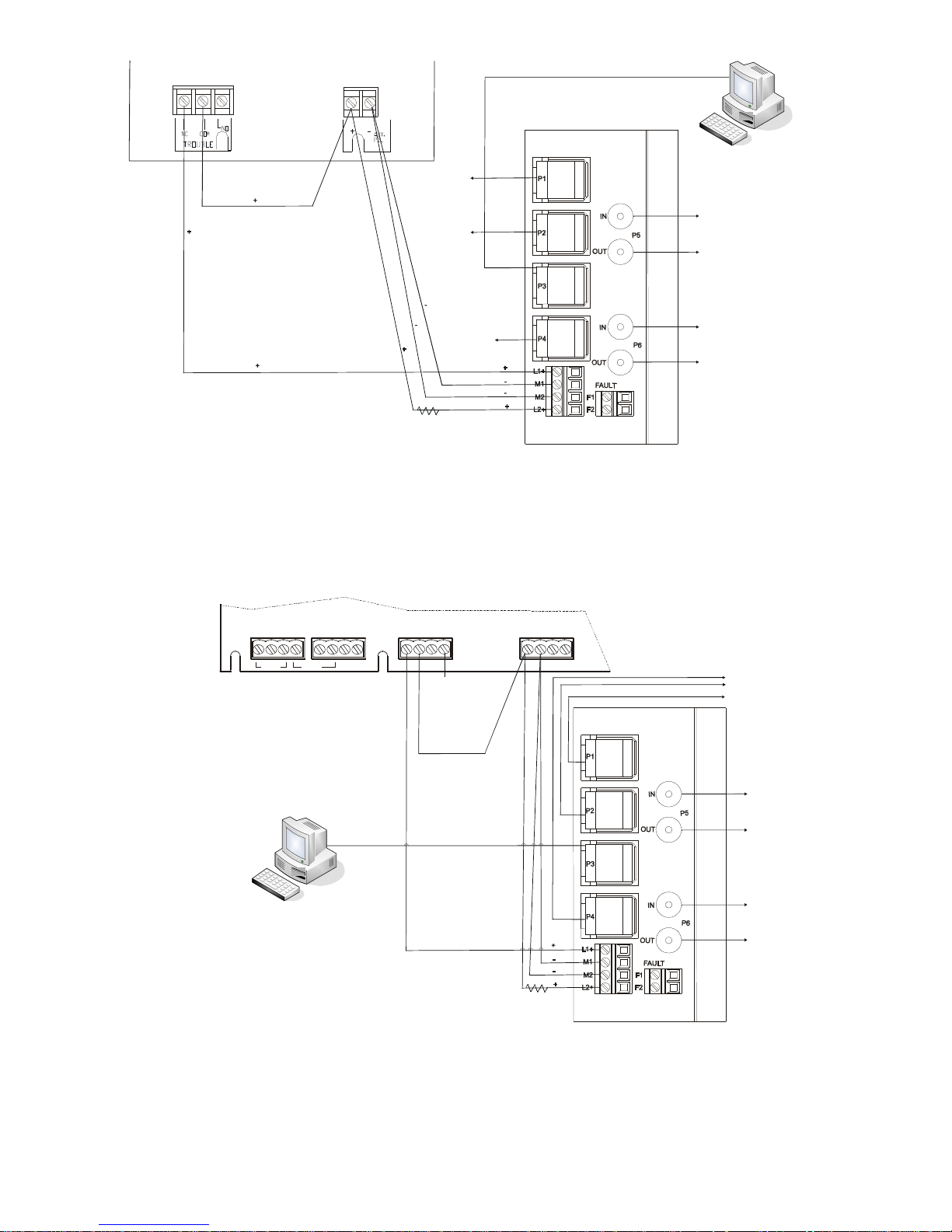
Figure 10
Scalance X204-2 Multimode or X204-2LD Single Mode Ethernet Fiber Switch Connection to PAD-3
TB11
1- 2+1
1+
1
INPUT 1 INPUT 2
4
-
D
A
P
TB12
NCCOM2- 2
1
L
Y
A
R
E
C
L
E
U
B
O
R
T
R
O
W
N
N
O
I
N
H
S
(
S
E
D
N
O
Y
C
D
B
N
A
T
D
3
@
V
0
A
2
R
O
I
S
I
F
E
V
T
S
U
O
S
D
M
E
I
T
I
L
R
I
V
E
P
U
S
N
U
TB13
NC COM NO
1 1
T
C
A
T
O
N
L
A
M
R
)
N
I
T
I
O
C
,
R
E
W
O
P
E
C
R
D
E
S
DO NOT USE
TB14
_+_
+
NAC1B NAC2B (NAC1A)
T
H
E
O
O
T
N
R
T
H
E
E
C
E
N
N
C
O
S
N
S
I
E
E
M
R
E
I
F
B
H
T
O
O
T
N
A
L
A
C
S
W
S
R
T
E
N
S
O
I
T
R
E
C
E
Siemens Building
Management System
Figure 11
Scalance X204-2 Multimode or X204-2LD Single Mode Ethernet Fiber Switch Connection to PAD-4
Siemens Industry, Inc.
Building Technologies Division
T
N
E
R
H
E
T
E
L
O
C
E
I
D
L
O
N
T
O
R
C
E
E
S
(
I
U
T
N
L
A
T
A
T
L
I
N
O
S
I
N
I
N
)
S
I
N
O
T
C
U
R
T
S
I
W
F
S
R
E
I
B
E
L
U
D
T
M
H
O
C
P/N 315-050537-37
CONFIGURING THE SCALANCE X204-2 MULTIMODE OR X204-2LD SINGLE MODE ETHERNET FIBER SWITCH
P1
P2
P3
P4
P5
P6
IN
OUT
IN
OUT
FAULT
F1
F2
L1+
M1
L2+
M2
ETHERNET
CONNECTIONS
P1
- P4
FIBER
CONNECTIONS
P5
- P6
This section describes how to assign an IP address to the Scalance X204-2 Multimode or X204-2LD Single Mode Ethernet Fiber Switch and the methods used for
determining IP addresses to assign to the switches. It also describes how to configure one of the switches as the ring master.
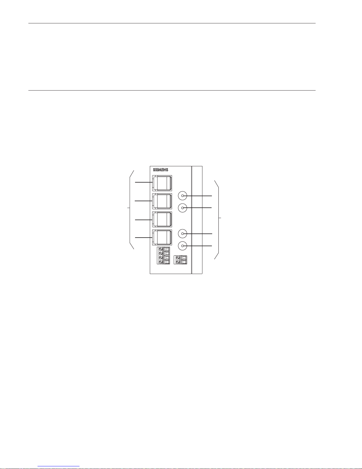
FIBER SWITCH The fiber switch can be configured independently or in the network. The initial
configuration of the fiber switch must be made before connecting it to the system.
The fiber switch has four RJ-45 jacks (P1-P4) for Ethernet connections and two pair of
fiber optic connection ports (P5-P6).
Each fiber switch must be programmed with a unique IP address. The recommended range of IP addresses is from 192.168.1.201 to 192.168.1.250. In addition to
the unique IP address, each switch is identified in the NCC by an address number
ranging from 201 to 250.
ETHERNET
CONNECTIONS
P1-P4
FIBER
CONNECTIONS
P5-P6
Figure 12
Scalance X204-2 Multimode/X204-2LD Single Mode Ethernet Fiber Switch Connections
The fiber switch is powered from the battery backed up local 24V power supply. It is
monitored by the NCC. Configuration is made using a Primary Setup Tool (PST) and a
web browser.
Primary Setup Tool The Primary Setup Tool (PST) is used to assign an IP address to an unconfigured fiber
switch. If a fiber switch is already initially configured with an IP address then the
Primary Setup tool is not needed
• Install the Primary Setup Tool using the setup executable from the CD
provided.
Siemens Industry, Inc.
Building Technologies Division
P/N 315-050537-38
• Open the CD drive and browse to the SW directory. Double click Setup.exe.
• Follow instructions until installation is complete.
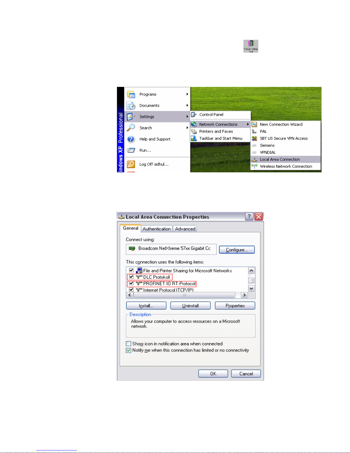
• Once completed, a Primary Setup Tool icon
• A DLC (Data Link Control) Protokoll and Profinet IO RT-Protocol need to be
installed on the laptop/PC being used to configure the fiber switch.
• To check that these protocols are installed, click Start->Network Connections->Local Area Connection.
Figure 13
Checking Local Area Connection
appears on the desktop.
• Verify that the DLC Protokoll and Profinet IO RT-Protocol are installed.
Figure 14
Verify Local Area Connection Items
Siemens Industry, Inc.
Building Technologies Division
P/N 315-050537-39
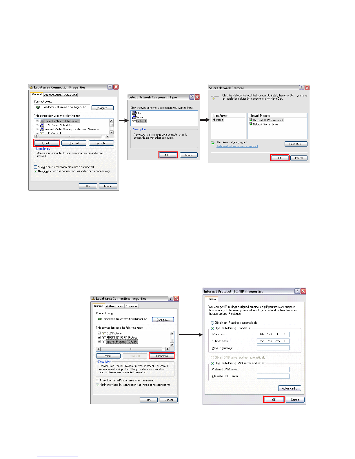
• If the DLC Protokoll and/or Profinet IO RT-Protocol are not installed:
* From the Local Area Connections Properties, click Install.
* Select Network Component Type “Protocol” and click Add.
* From the Select Network Protocol window, click “Have Disk”.
* Select the DLC Protokoll from Network Protocol column, then
click OK.
Figure 15
DLC Protokoll and/or Profinet IO RT-Protocol Installation
• The laptop/PC being used to configure a switch needs to be on the same
network as the fiber switches. To do this temporarily change the IP address
of the laptop/PC.
* From Local Area Connection Properties dialog window select
“Internet Protocol (TCP/IP)” and click Properties.
* Choose “Use the following IP address” and pick an address in
the same network as the fiber switch.
* Use a subnet mask of 255.255.255.0.
Figure 16
Changing the IP Address of the Laptop/PC
Siemens Industry, Inc.
Building Technologies Division
P/N 315-050537-310
 Loading...