

Siemens SCALANCE X-200RNA, SCALANCE X204RNA EEC Operating Instructions Manual

SIMATIC NET
Industrial Ethernet switches
SCALANCE X-200RNA
Introduction
1
Operating Instructions
Safety notices
Network topologies and
redundancy
Descriptions of the products
Installation
Connecting up
Functional description and
configuration using Web
Based Management
Approvals and marking
2
3
4
5
6
7
8
Technical specifications
Accessories and compatible
devices
Dimension drawings
9
10
11
10/2016
C79000-G8976-C342-04

Legal information
Warning notice system
This manual contains notices you have to observe in order to ensure your personal safety, as well as to prevent
damage to property. The notices referring to your personal safety are highlighted in the manual by a safety alert
symbol, notices referring only to property damage have no safety alert symbol. These notices shown below are
graded according to the degree of danger.
DANGER
indicates that death or severe personal injury will result if proper precautions are not taken.
WARNING
indicates that death or severe personal injury may result if proper precautions are not taken.
CAUTION
indicates that minor personal injury can result if proper precautions are not taken.
NOTICE
indicates that property damage can result if proper precautions are not taken.
If more than one degree of danger is present, the warning notice representing the highest degree of danger will be
used. A notice warning of injury to persons with a safety alert symbol may also include a warning relating to property
damage.
Qualified Personnel
The product/system described in this documentation may be operated only by personnel qualified for the specific
task in accordance with the relevant documentation, in particular its warning notices and safety instructions. Qualified
personnel are those who, based on their training and experience, are capable of identifying risks and avoiding
potential hazards when working with these products/systems.
Proper use of Siemens products
Note the following:
WARNING
Siemens products may only be used for the applications described in the catalog and in the relevant technical
documentation. If products and components from other manufacturers are used, these must be recommended or
approved by Siemens. Proper transport, storage, installation, assembly, commissioning, operation and
maintenance are required to ensure that the products operate safely and without any problems. The permissible
ambient conditions must be complied with. The information in the relevant documentation must be observed.
Trademarks
All names identified by ® are registered trademarks of Siemens AG. The remaining trademarks in this publication
may be trademarks whose use by third parties for their own purposes could violate the rights of the owner.
Disclaimer of Liability
We have reviewed the contents of this publication to ensure consistency with the hardware and software described.
Since variance cannot be precluded entirely, we cannot guarantee full consistency. However, the information in
this publication is reviewed regularly and any necessary corrections are included in subsequent editions.
Siemens AG
Division Process Industries and Drives
Postfach 48 48
90026 NÜRNBERG
GERMANY
C79000-G8976-C342-04
Ⓟ 02/2017 Subject to change
Copyright © Siemens AG 2013 - 2016.
All rights reserved

Table of contents
1 Introduction...................................................................................................................................................7
2 Safety notices.............................................................................................................................................13
3 Network topologies and redundancy..........................................................................................................17
3.1 PRP........................................................................................................................................17
3.2 HSR........................................................................................................................................20
3.3 HSR-PRP coupling.................................................................................................................24
3.3.1 Coupling of two HSR rings via a PRP network......................................................................24
3.3.2 Coupling of two PRP networks via an HSR ring....................................................................26
4 Descriptions of the products.......................................................................................................................29
4.1 Overview of the product characteristics.................................................................................29
4.2 Unpacking and checking........................................................................................................31
4.3 Components of the product....................................................................................................32
4.4 SCALANCE X204RNA...........................................................................................................33
4.4.1 Product characteristics...........................................................................................................33
4.4.1.1 SCALANCE X204RNA (PRP) product characteristics...........................................................33
4.4.1.2 SCALANCE X204RNA (HSR) product characteristics...........................................................34
4.4.2 SCALANCE X204RNA TP interfaces.....................................................................................35
4.5 SCALANCE X204RNA EEC..................................................................................................37
4.5.1 Product characteristics...........................................................................................................37
4.5.1.1 SCALANCE X204RNA EEC (PRP) product characteristics...................................................37
4.5.1.2 SCALANCE X204RNA EEC (PRP/HSR) product characteristics..........................................38
4.5.1.3 SCALANCE X204RNA EEC (HSR) product characteristics..................................................39
4.5.2 SCALANCE X204RNA EEC TP interfaces............................................................................40
4.5.3 SCALANCE X204RNA EEC SFP interface............................................................................42
4.6 C-PLUG..................................................................................................................................44
4.7 SELECT/SET button..............................................................................................................46
4.8 LEDs......................................................................................................................................49
4.8.1 SCALANCE X-200RNA (PRP)...............................................................................................49
4.8.1.1 Fault LED...............................................................................................................................49
4.8.1.2 Power LED.............................................................................................................................49
4.8.1.3 Port LED.................................................................................................................................50
4.8.1.4 LED displays during startup...................................................................................................50
4.8.1.5 Mode LED (SCALANCE X204RNA EEC (PRP/HSR))...........................................................51
4.8.2 SCALANCE X-200RNA (HSR)...............................................................................................51
4.8.2.1 Fault LED...............................................................................................................................51
4.8.2.2 Power LED.............................................................................................................................51
4.8.2.3 Port LED.................................................................................................................................52
4.8.2.4 LED displays during startup...................................................................................................52
4.8.2.5 Mode LED (SCALANCE X204RNA EEC (PRP/HSR))...........................................................53
SCALANCE X-200RNA
Operating Instructions, 10/2016, C79000-G8976-C342-04 3

Table of contents
5 Installation..................................................................................................................................................55
5.1 Types of installation...............................................................................................................55
5.2 Mounting on DIN rails.............................................................................................................57
5.3 Wall mounting........................................................................................................................60
6 Connecting up............................................................................................................................................63
6.1 Power supply..........................................................................................................................63
6.2 Signaling contact....................................................................................................................66
6.3 SFP transceiver......................................................................................................................68
6.4 Grounding..............................................................................................................................69
7 Functional description and configuration using Web Based Management.................................................71
7.1 Introduction............................................................................................................................71
7.2 Prerequisite............................................................................................................................72
7.3 Assignment of an IP address.................................................................................................74
7.3.1 Introduction............................................................................................................................74
7.3.2 Initial assignment of an IP address........................................................................................75
7.4 Initializing the SCALANCE X204RNA EEC (PRP/HSR)........................................................77
7.5 LED simulation of the WBM...................................................................................................79
7.6 Working with the WBM...........................................................................................................81
7.7 The "System" menu...............................................................................................................82
7.7.1 System Configuration.............................................................................................................82
7.7.2 System Identification & Maintenance.....................................................................................83
7.7.3 System Restart & Defaults.....................................................................................................84
7.7.4 System Save & Load..............................................................................................................86
7.7.5 System Version Numbers......................................................................................................88
7.7.6 System Passwords.................................................................................................................89
7.7.7 System SELECT/SET button.................................................................................................90
7.7.8 System Event Log Table........................................................................................................92
7.7.9 C-PLUG Information...............................................................................................................93
7.8 The "X200" menu...................................................................................................................95
7.8.1 X200 Status............................................................................................................................95
7.8.2 PRP configuration..................................................................................................................97
7.8.3 HSR Coupling Configuration..................................................................................................98
7.8.4 Fault Mask..............................................................................................................................99
7.9 The "Agent" menu................................................................................................................103
7.9.1 Agent Configuration ............................................................................................................103
7.9.2 Agent Ping............................................................................................................................105
7.9.3 Agent SNMP Configuration..................................................................................................106
7.9.4 SNMP Trap Configuration....................................................................................................108
7.9.5 SNMP v3 Groups.................................................................................................................109
7.9.6 SNMP v3 User.....................................................................................................................111
7.9.7 Agent Timeout Configuration...............................................................................................113
7.9.8 Agent Event Configuration...................................................................................................114
7.9.9 Agent E-Mail Configuration..................................................................................................117
SCALANCE X-200RNA
4 Operating Instructions, 10/2016, C79000-G8976-C342-04

Table of contents
7.9.10 Agent Syslog Configuration..................................................................................................118
7.9.11 Agent DHCP Configuration..................................................................................................119
7.9.12 Agent Time Configuration....................................................................................................121
7.10 The "Switch" menu...............................................................................................................123
7.10.1 Introduction..........................................................................................................................123
7.10.2 Switch Config.......................................................................................................................123
7.10.3 Port status............................................................................................................................124
7.10.4 Switch Forwarding Database...............................................................................................125
7.10.5 the Statistics menu...............................................................................................................127
7.10.6 Packet Size Statistic.............................................................................................................127
7.10.7 Packet Type Statistic............................................................................................................129
7.10.8 Packet Error Statistic............................................................................................................132
7.10.9 PRP Statistic........................................................................................................................134
7.10.10 Redundancy Statistic...........................................................................................................135
8 Approvals and marking.............................................................................................................................137
9 Technical specifications............................................................................................................................143
10 Accessories and compatible devices........................................................................................................147
10.1 Accessories..........................................................................................................................147
10.2 PRP-compatible devices......................................................................................................149
11 Dimension drawings.................................................................................................................................153
Index.........................................................................................................................................................157
SCALANCE X-200RNA
Operating Instructions, 10/2016, C79000-G8976-C342-04 5

Table of contents
SCALANCE X-200RNA
6 Operating Instructions, 10/2016, C79000-G8976-C342-04

Introduction
Overview of SCALANCE X-200RNA
The SCALANCE X-200RNA product family is part of the SCALANCE X product family. Below,
you will find a brief overview of this product family.
The SCALANCE X family comprises various product lines that complement each other and
that are carefully tuned to specific automation tasks.
What is possible?
The IE switches of the SCALANCE X-200RNA product line allow the cost-effective setup of
IE structures with PRP or HSR functionality. You can also implement the transition between a
PRP and an HSR network with the SCALANCE X-200RNA.
Purpose of the Operating Instructions
These Operating Instructions support you when commissioning networks with the IE switches
of the SCALANCE X200RNA product line.
1
Validity of the Operating Instructions
These Operating Instructions are valid for the following IE switches of the SCALANCE
X-200RNA product line:
IE switch MLFB
SCALANCE X204RNA 6GK5204-0BA00-2KB2 (PRP)
SCALANCE X204RNA EEC 6GK5204-0BS00-3LA3 (PRP)
6GK5204-0BA00-2MB2 (HSR)
6GK5204-0BS00-2NA3 (HSR)
6GK5204-0BS00-3PA3 (PRP/HSR)
SCALANCE X-200RNA
Operating Instructions, 10/2016, C79000-G8976-C342-04 7

Introduction
Product names of the devices in these operating instructions
The descriptions in these operating instructions always apply to the devices of the SCALANCE
X‑200RNA product line listed under "Validity of the Operating Instructions" in this document
unless the description relates to a specific device of the product line.
Product name Covers the following devices:
SCALANCE X-200RNA SCALANCE X204RNA (PRP)
SCALANCE X204RNA (HSR)
SCALANCE X204RNA EEC (PRP)
SCALANCE X204RNA EEC (HSR)
SCALANCE X204RNA EEC (PRP/HSR)
SCALANCE X-200RNA (PRP) SCALANCE X204RNA (PRP)
SCALANCE X204RNA EEC (PRP)
SCALANCE X204RNA EEC (PRP/HSR) in "PRP" mode
SCALANCE X-200RNA (HSR) SCALANCE X204RNA (HSR)
SCALANCE X204RNA EEC (HSR)
SCALANCE X204RNA EEC (PRP/HSR) in "HSR" mode
SCALANCE X204RNA SCALANCE X204RNA (PRP)
SCALANCE X204RNA (HSR)
SCALANCE X204RNA EEC SCALANCE X204RNA EEC (PRP)
SCALANCE X204RNA EEC (HSR)
SCALANCE X204RNA EEC (PRP/HSR)
Note
SCALANCE X204RNA EEC (PRP/HSR)
This device can be configured either as a PRP device or as an HSR device.
If you configure the device as a PRP device, it behaves in exactly the same way as the
SCALANCE X204RNA EEC (PRP).
If you configure the device as an HSR device, it behaves in exactly the same way as the
SCALANCE X204RNA EEC (HSR).
Further documentation
The "SIMATIC NET Industrial Ethernet Twisted Pair and Fiber Optic Networks" manual and
the "Industrial Ethernet Network Manual" contain additional information on other SIMATIC NET
products that you can operate along with the devices of the SCALANCE X‑200RNA product
line in an Industrial Ethernet network. You will find further documentation on the Siemens
Automation Customer Support pages.
SCALANCE X-200RNA
8 Operating Instructions, 10/2016, C79000-G8976-C342-04

Overview of the IE switches SCALANCE X-200RNA
The IE switches SCALANCE X-200RNA are available in different versions. These are listed
in the table below for a better overview:
IE switch MLFB Supported modes
SCALANCE X204RNA (PRP) 6GK5204-0BA00-2KB2 PRP ↔ Standard Ethernet
SCALANCE X204RNA (HSR) 6GK5204-0BA00-2MB2 HSR ↔ standard Ethernet;
SCALANCE X204RNA EEC (PRP) 6GK5204-0BS00-3LA3 PRP ↔ Standard Ethernet
SCALANCE X204RNA EEC (HSR) 6GK5204-0BS00-2NA3 HSR ↔ standard Ethernet;
SCALANCE X204RNA EEC (PRP/HSR) 6GK5204-0BS00-3PA3 PRP ↔ standard Ethernet
Finding information
Introduction
PRP ↔ HSR link
HSR ↔ PRP link
HSR ↔ PRP link
HSR ↔ standard Ethernet;
HSR ↔ PRP link
To help you to find the information you require more quickly, the manual includes not only the
table of contents but also the following sections in the Appendix:
● Index
Audience
These Operating Instructions are intended for persons commissioning Ethernet networks with
the "Parallel Redundancy Protocol" (PRP) and/or "High-availability Seamless Redundancy
Protocol (HSR)".
Standards and approvals
The devices of the SCALANCE X-200RNA product line meet the requirements for the CE mark.
For more detailed information, refer to the section "Approvals and marking (Page 137)" in these
Operating Instructions.
Note
The specified approvals apply only when the corresponding mark is printed on the product.
Industry Online Support
In addition to the product documentation, the comprehensive online information platform of
Siemens Industry Online Support at the following Internet address:
(
http://support.automation.siemens.com/WW/llisapi.dll?
func=cslib.csinfo2&aktprim=99&lang=en)
SCALANCE X-200RNA
Operating Instructions, 10/2016, C79000-G8976-C342-04 9

Introduction
Apart from news, there you will also find:
● Project information: Manuals, FAQs, downloads, application examples etc.
● Contacts, Technical Forum
● The option submitting a support query:
(https://support.automation.siemens.com/WW/llisapi.dll?
func=cslib.csinfo&lang=en&objid=38718979&caller=view)
● Our service offer:
Right across our products and systems, we provide numerous services that support you in
every phase of the life of your machine or system - from planning and implementation to
commissioning, through to maintenance and modernization.
You will find contact data on the Internet at the following address:
(http://www.automation.siemens.com/partner/guiwelcome.asp?lang=en)
SITRAIN ‑ Training for Industry
The training offer includes more than 300 courses on basic topics, extended knowledge and
special knowledge as well as advanced training for individual sectors - available at more than
130 locations. Courses can also be organized individually and held locally at your location.
You will find detailed information on the training curriculum and how to contact our customer
consultants at the following Internet address:
(www.siemens.com/sitrain)
Security information
Siemens provides products and solutions with industrial security functions that support the
secure operation of plants, systems, machines and networks.
In order to protect plants, systems, machines and networks against cyber threats, it is
necessary to implement – and continuously maintain – a holistic, state-of-the-art industrial
security concept. Siemens’ products and solutions only form one element of such a concept.
Customer is responsible to prevent unauthorized access to its plants, systems, machines and
networks. Systems, machines and components should only be connected to the enterprise
network or the internet if and to the extent necessary and with appropriate security measures
(e.g. use of firewalls and network segmentation) in place.
Additionally, Siemens’ guidance on appropriate security measures should be taken into
account. For more information about industrial security, please visit
http://www.siemens.com/industrialsecurity (http://www.siemens.com/industrialsecurity)
Siemens’ products and solutions undergo continuous development to make them more secure.
Siemens strongly recommends to apply product updates as soon as available and to always
use the latest product versions. Use of product versions that are no longer supported, and
failure to apply latest updates may increase customer’s exposure to cyber threats.
To stay informed about product updates, subscribe to the Siemens Industrial Security RSS
Feed under
https://support.industry.siemens.com/cs/ww/en/ps/15247/pm (https://
support.industry.siemens.com/cs/ww/en/ps/15247/pm).
SCALANCE X-200RNA
10 Operating Instructions, 10/2016, C79000-G8976-C342-04

License conditions
Trademarks
Introduction
Note
Open source software
Read the license conditions for open source software carefully before using the product.
You will find license conditions in the following documents on the supplied data medium:
● DOC_OSS-SCALANCE-X_74.pdf
● DC_LicenseSummaryScalanceX200RNA_76.pdf
You will find these documents on the product DVD in the following directory: /Open Source
Information
The following and possibly other names not identified by the registered trademark sign ® are
registered trademarks of Siemens AG:
SIMATIC NET, SCALANCE, C-PLUG, OLM
SIMATIC NET glossary
Explanations of many of the specialist terms used in this documentation can be found in the
SIMATIC NET glossary.
You will find the SIMATIC NET glossary on the Internet at the following address:
50305045 (http://support.automation.siemens.com/WW/view/en/50305045)
SCALANCE X-200RNA
Operating Instructions, 10/2016, C79000-G8976-C342-04 11

Introduction
SCALANCE X-200RNA
12 Operating Instructions, 10/2016, C79000-G8976-C342-04

Safety notices
Safety notices on the use of the device
The following safety notices must be adhered to when setting up and operating the device and
during all associated work such as installation, connecting up, replacing devices or opening
the device.
General notices
WARNING
Safety extra low voltage
The SCALANCE X204RNA is designed for operation with Safety Extra-Low Voltage (SELV)
by a Limited Power Source (LPS). (This does not apply to the SCALANCE X204RNA EEC.)
This means that only SELV / LPS complying with IEC 60950 1 / EN 60950 1 / VDE 0805 1
must be connected to the power supply terminals. The power supply unit for the equipment
power supply must comply with NEC Class 2, as described by the National Electrical Code
(r) (ANSI / NFPA 70).
2
If the equipment is connected to a redundant power supply (two separate power supplies),
both must meet these requirements.
WARNING
Maximum current
The maximum current via the terminals is 10 A. You should therefore include a fuse that trips
at a current higher than 10 A. The fuse must meet the following requirements:
● Suitable for 300 VDC / 250 VAC / max. 10 A
● Breaking current at least 10 kA
● UL/CSA listed (UL 248-1 / CSA 22.2 No. 248.1)
As an alternative, the following requirements:
● Breaking current at least 10 kA
● Approved in compliance with IEC 60127-1 / EN 60127-1
● Breaking characteristics: B or C for a circuit breaker or slow-blow fuse
WARNING
Opening the device
WARNING – EXPLOSION HAZARD
DO NOT OPEN WHEN ENERGIZED.
SCALANCE X-200RNA
Operating Instructions, 10/2016, C79000-G8976-C342-04 13
Safety notices
General notices on use in hazardous areas
WARNING
Risk of explosion when connecting or disconnecting the device
WARNING – EXPLOSION HAZARD
DO NOT CONNECT OR DISCONNECT EQUIPMENT WHEN A FLAMMABLE OR
COMBUSTIBLE ATMOSPHERE IS PRESENT.
WARNING
Replacing components
WARNING – EXPLOSION HAZARD
SUBSTITUTION OF COMPONENTS MAY IMPAIR SUITABILITY FOR CLASS I, DIVISION
2 OR ZONE 2.
WARNING
Requirements for the cabinet/enclosure
When used in hazardous environments corresponding to Class I, Division 2 or Class I, Zone
2, the device must be installed in a cabinet or a suitable enclosure.
General notices on use in hazardous areas according to ATEX (SCALANCE X204RNA only)
WARNING
Requirements for the cabinet/enclosure
To comply with EC Directive 94/9 (ATEX95), this enclosure must meet the requirements of
at least IP54 in compliance with EN 60529.
WARNING
Suitable cables for temperatures in excess of 70 °C
If the cable or conduit entry point exceeds 70°C or the branching point of conductors exceeds
80°C, special precautions must be taken. If the equipment is operated in an air ambient in
excess of 50 °C to 70 °C, only use cables with admitted maximum operating temperature of
at least 80 °C.
WARNING
Protection against transient voltage surges
Take measures to prevent transient voltage surges of more than 40% of the rated voltage.
This is the case if you only operate devices with SELV (safety extra-low voltage).
SCALANCE X-200RNA
14 Operating Instructions, 10/2016, C79000-G8976-C342-04

Safety requirements 100 .. 240 VAC (SCALANCE X204RNA EEC only)
Safety requirements for installation
According to the IEC 61131-2 standard and therefore in accordance with the EU directive
2006/95/EC (Low Voltage Directive), the devices are "open equipment" and in accordance
with UL/CSA certification, they are an "open type".
To fulfill requirements for safe operation with regard to mechanical stability, flame retardation,
stability, and shock-hazard protection, the following alternative types of installation are
specified:
● Installation in a suitable cabinet.
● Installation in a suitable enclosure.
● Installation in a suitably equipped, enclosed control room.
Safety notices
SCALANCE X-200RNA
Operating Instructions, 10/2016, C79000-G8976-C342-04 15

Safety notices
SCALANCE X-200RNA
16 Operating Instructions, 10/2016, C79000-G8976-C342-04

Network topologies and redundancy
3.1 PRP
Parallel Redundancy Protocol
The "Parallel Redundancy Protocol" is a redundancy protocol for Ethernet networks. It is
defined in Part 3 of the IEC 62439 standard. The devices of the SCALANCE X-200RNA product
line support the PRP method. The areas of application of PRP are distributed real-time
applications with high reliability demands that depend on the high availability of the network.
Compared with classic fault-tolerant networks, PRP provides bumpless redundancy. This
redundancy method allows data communication to be maintained without interruption/
reconfiguration time if there are interruptions in the network. Other redundancy methods have
a network reconfiguration time of, for example 200 ms (MRP, 50 nodes in the ring) or 300 ms
(High Speed Redundancy, 50 nodes in the ring) and cannot therefore be used for substation
applications or other applications that require high network availability.
The PRP method has the advantage that it uses parallel, separate networks made up of
standard network components. The end devices that use this method are connected to the
two networks via a preceding device or via two integrated device interfaces. This means that
the frame of the end device can be transferred at the same time via both networks. If a
transmission path is interrupted, the frame arrives at its destination via the second path.
3
The devices of the SCALANCE X-200RNA product line are used to connect end devices
without integrated PRP interfaces to parallel networks.
Note
SCALANCE X204RNA EEC (PRP/HSR)
If you initialize the device as a PRP device, it behaves in exactly the same way as the
SCALANCE X204RNA EEC (PRP).
Which topologies can be implemented?
With the devices of the SCALANCE X-200RNA (PRP) product line, nodes or entire network
segments without PRP capability can be connected to a "Parallel Redundancy Protocol"
network.
The products with PRP capability of the SCALANCE X-200RNA product line can be used to
implement an integrated solution for network components and protective devices for a
substation and also process application.
SCALANCE X-200RNA
Operating Instructions, 10/2016, C79000-G8976-C342-04 17
Network topologies and redundancy
3.1 PRP
The SCALANCE X-200RNA can manage a maximum of 1023 MAC addresses.
Note
Keep to the maximum permitted cable lengths of the devices you are using. You will find the
permitted cable lengths in the technical specifications.
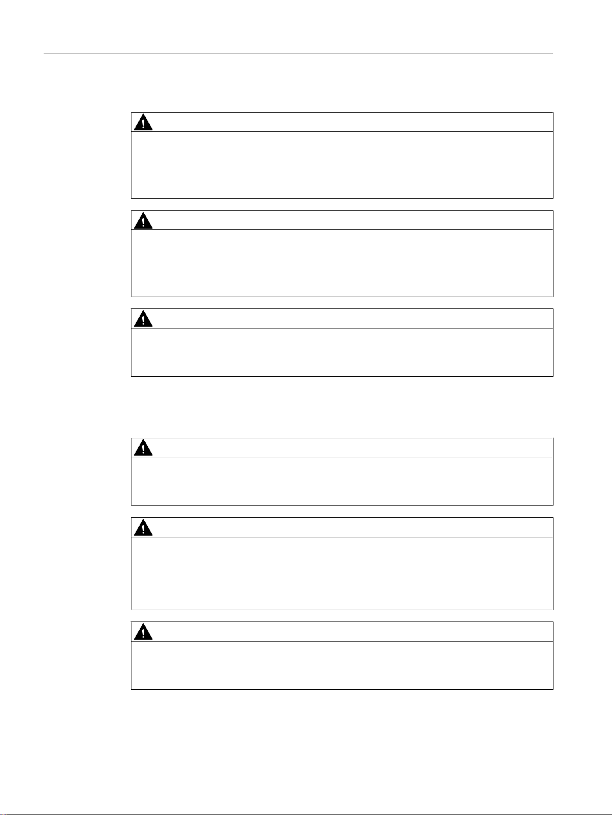
Example
Figure 3-1 Schematic diagram of the "Parallel Redundancy Protocol"
With the "Parallel Redundancy Protocol" (PRP), each node must transmit Ethernet frames on
two independent, parallel networks. These are two physically separate networks with a bus
(linear), star or ring topology. The PRP destination device must also be connected to the two
networks. This then receives each frame twice. The first frame is forwarded to the application.
SCALANCE X-200RNA
18 Operating Instructions, 10/2016, C79000-G8976-C342-04

Network topologies and redundancy
3.1 PRP
The second frame received is recognized and discarded. This achieves N-1 redundancy
without reconfiguration (= bumpless switchover).
Note
Overlong frames
When a SCALANCE X204RNA IE switch feeds a frame with the maximum length into a PRP
network, the IE switch appends a PRP trailer to the frame. Appending the PRP trailer results
in an overlong frame that exceeds the maximum permitted frame length (according to the IEEE
802.3 standard).
To prevent data loss with overlong frames, all network components located in a PRP network
must support a frame length of at least 1528 bytes.
You will find a list of compatible devices that support processing of overlong frames in the
section "PRP-compatible devices (Page 149)".
There are already end devices equipped with two Ethernet interfaces that are capable of
handling the "Parallel Redundancy Protocol" (Double Attached Nodes PRP = DANP).
On the other hand, there are many end devices starting with S7 controllers right through to
control computers that communicate using TCP/IP but do not support PRP, and some even
have only one Ethernet Interface. With all these devices, a SCALANCE X-200RNA can be
connected upstream from them. This allows access for Single Attached Nodes (SAN) to PRP
networks.
Industrial Ethernet bus (linear), star or ring structures with switching functionality can be
implemented cost-effectively with devices of the SCALANCE X product line. You will find a list
of usable network components in "Accessories and compatible devices (Page 147)".
SCALANCE X-200RNA
Operating Instructions, 10/2016, C79000-G8976-C342-04 19

Network topologies and redundancy
3.2 HSR
3.2 HSR
High-availability Seamless Redundancy Protocol (HSR)
The "High-availability Seamless Redundancy" protocol is a redundancy protocol for Ethernet
networks. It is defined in Part 3 of the IEC 62439 standard. The devices of the SCALANCE
X-200RNA product line support the HSR method. The areas of application of HSR are
distributed real-time applications with high reliability demands that depend on the high
availability of the network. Compared with classic fault-tolerant networks, HSR provides
bumpless redundancy. This redundancy method allows data communication to be maintained
without interruption/reconfiguration time if there are interruptions in the network. Other
redundancy procedures have a reconfiguration time of the network of, for example 200 ms
(MRP, 50 nodes in the ring) or 300 ms (High Speed Redundancy, 50 nodes in the ring) and
cannot therefore be used for substation applications or other applications that require high
network availability.
The HSR method has the advantage that the communication redundancy is achieved by the
configuration as a ring. This means there is no need for other standard network components
(switches) within a network. The end devices that use this method are connected to the two
networks via a preceding device or via two integrated device interfaces. This means that the
frame of the end device can be transferred at the same time in both directions of the ring. If a
transmission path is interrupted, the frame arrives its destination via the other path.
The devices of the SCALANCE X-200RNA product line are used to connect end devices
without integrated HSR interfaces to HSR networks.
Note
SCALANCE X204RNA EEC (PRP/HSR)
If you initialize the device as an HSR device, it behaves in exactly the same way as the
SCALANCE X204RNA EEC (HSR).
Which topologies can be implemented?
With the devices of the SCALANCE X-200RNA (HSR) product line, nodes or entire network
segments without HSR capability can be connected to a "High-availability Seamless
Redundancy Protocol" network.
The products with HSR capability of the SCALANCE X-200RNA product line can be used to
implement an integrated solution for network components and protective devices for a
substation and also process application.
You also have the option for a redundant or non-redundant coupling to a PRP network.
The SCALANCE X-200RNA can manage a maximum of 1023 MAC addresses.
Note
Keep to the maximum permitted cable lengths of the devices you are using. You will find the
permitted cable lengths in the technical specifications.
SCALANCE X-200RNA
20 Operating Instructions, 10/2016, C79000-G8976-C342-04
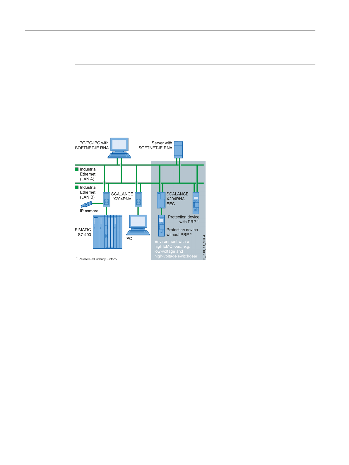
Example
Network topologies and redundancy
3.2 HSR
Figure 3-2 Basic diagram of a single HSR ring
With the High-availability Seamless Redundancy Protocol (HSR), each node must feed the
Ethernet frames it wants to send in both directions of the ring. The HSR target device must
also be connected via two ports with the ring. It now receives the same frame from both
directions, in other words twice. The first frame is forwarded to the application. The second
frame received is recognized and discarded. This achieves N-1 redundancy without
reconfiguration (= bumpless switchover).
There are already end devices equipped with two Ethernet interfaces that are capable of using
the "High-availability Seamless Redundancy Protocol" (Double Attached Nodes HSR = DANH).
On the other hand, there are many end devices starting with S7 controllers right through to
control computers that communicate using TCP/IP but do not support HSR and some even
have only one Ethernet interface. With all these devices, a SCALANCE X-200RNA can be
connected upstream from them.
SCALANCE X-200RNA
Operating Instructions, 10/2016, C79000-G8976-C342-04 21
Network topologies and redundancy
3.2 HSR
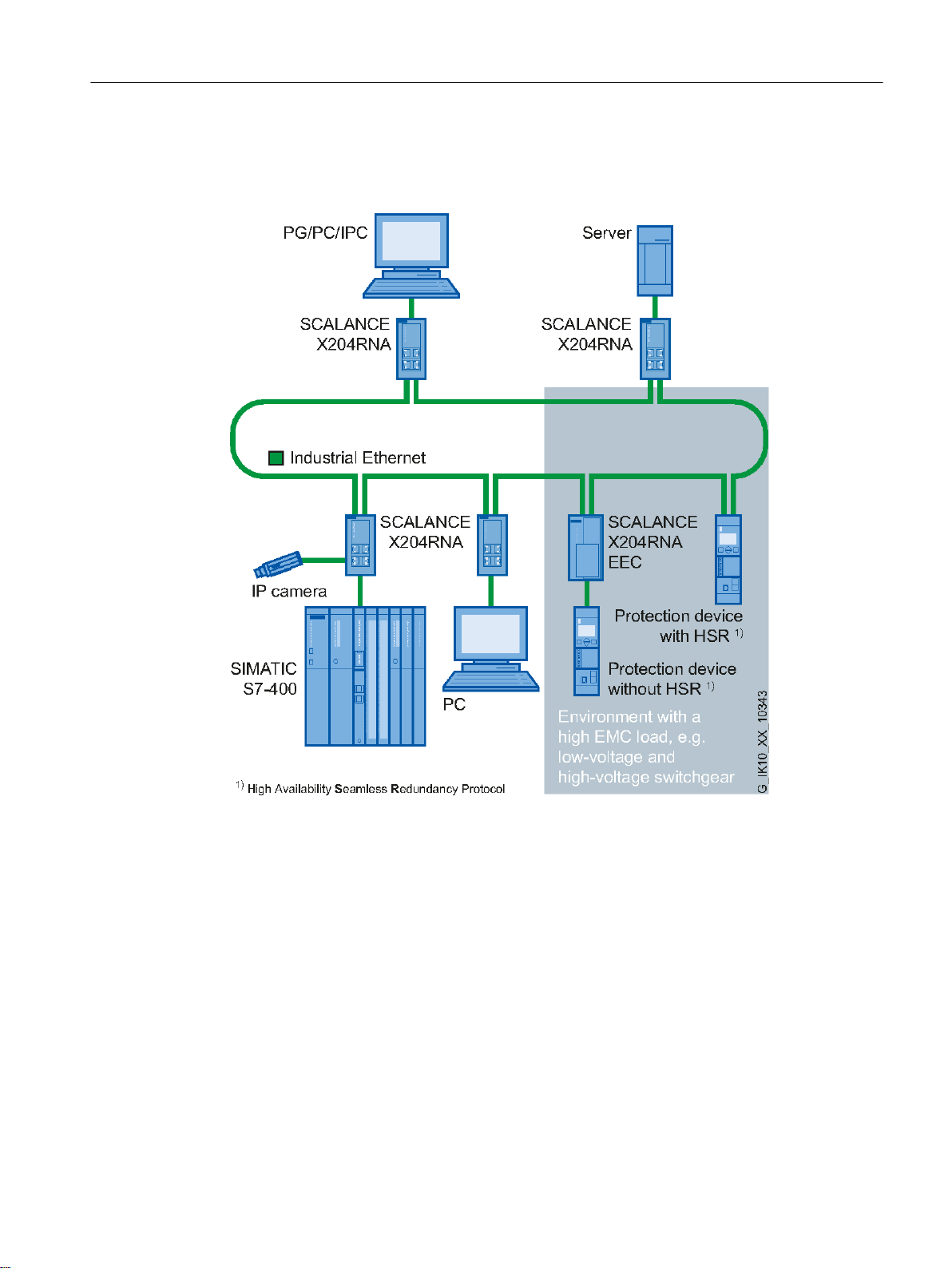
Transition between HSR and PRP (redundant)
Figure 3-3 Basic diagram of the redundant HSR-PRP link
The devices of the SCALANCE X-200RNA product line allow a link with a PRP network. This
coupling is in redundant form, as described in standard IEC62439-3. Two SCALANCE
X-200RNA devices are required. One device is connected with the PRP network LAN A, the
other with LAN B.
SCALANCE X-200RNA
22 Operating Instructions, 10/2016, C79000-G8976-C342-04

This means complete communication is still ensured even if one transition point fails. SANs
connected without RedBox to the decoupled PRP network are an exception from this rule.
Transition between HSR and PRP (non-redundant)
The coupling with a PRP network can also take place non-redundantly. In this case, only one
SCALANCE X-200RNA device is required. The device is connected to the PRP network LAN
A and to LAN B.
Note
This type of linking is not recommended because if the transition point fails, the communication
between HSR and PRP nodes is interrupted.
Network topologies and redundancy
3.2 HSR
SCALANCE X-200RNA
Operating Instructions, 10/2016, C79000-G8976-C342-04 23
+65
353
/$1$
353
/$1%
+65
6&$/$1&(
;50
6&$/$1&(
;50
6&$/$1&(
;51$
6&$/$1&(
;51$
6&$/$1&(
;51$
6&$/$1&(
;51$
6&$/$1&(
;51$
6&$/$1&(
;51$
6&$/$1&(
;51$
6&$/$1&(
;51$
6,0$7,&6
6,0$7,&6
3&
3&
Network topologies and redundancy
3.3 HSR-PRP coupling
3.3 HSR-PRP coupling
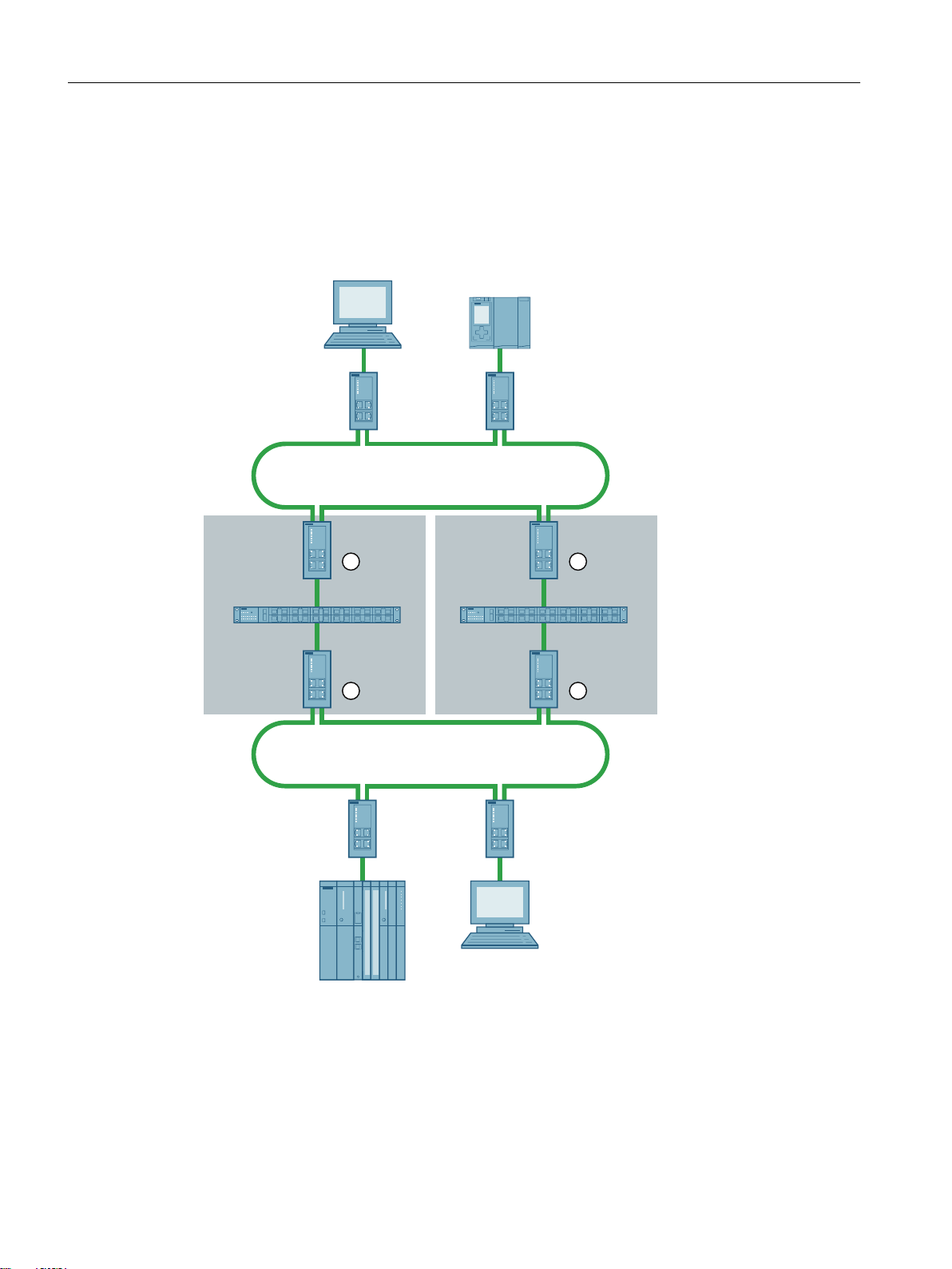
3.3.1 Coupling of two HSR rings via a PRP network
Figure 3-4 Topology of a coupling of two HSR rings via a PRP network
SCALANCE X-200RNA
24 Operating Instructions, 10/2016, C79000-G8976-C342-04

Settings in WBM
You specify the functionality of the devices SCALANCE X204RNA ① to ④ relating to the
coupling of the two rings on the WBM page X200 > Coupling Configuration. You need to
configure the following parameters:
● Coupling Mode
● NetID
Configuration of the "Coupling Mode" parameter
Setting for device ① and ③
Redundant HSR PRP coupling, LAN A (The port P2/B is open and must not be used.)
Setting for device ② and ④
Redundant HSR PRP coupling, LAN B (The port P1/A is open and must not be used.)
Configuration of the "NetID" parameter
The network ID of the PRP network is specified with this parameter. The valid range of values
is 1 to 6. The SCALANCE X204RNA devices between the two rings belong to the same PRP
network, therefore you need to set the same NetID for all devices ① to ④.
Network topologies and redundancy
3.3 HSR-PRP coupling
SCALANCE X-200RNA
Operating Instructions, 10/2016, C79000-G8976-C342-04 25
+65
353
353
6&$/$1&(
;51$
6&$/$1&(
;51$
6&$/$1&(
;51$
6&$/$1&(
;51$
6&$/$1&(
;51$
6&$/$1&(
;51$
6&$/$1&(
;51$
6,0$7,&6
&351$
3&
6,0$7,&6
3&
/$1$/$1%
/$1$/$1%
Network topologies and redundancy
3.3 HSR-PRP coupling
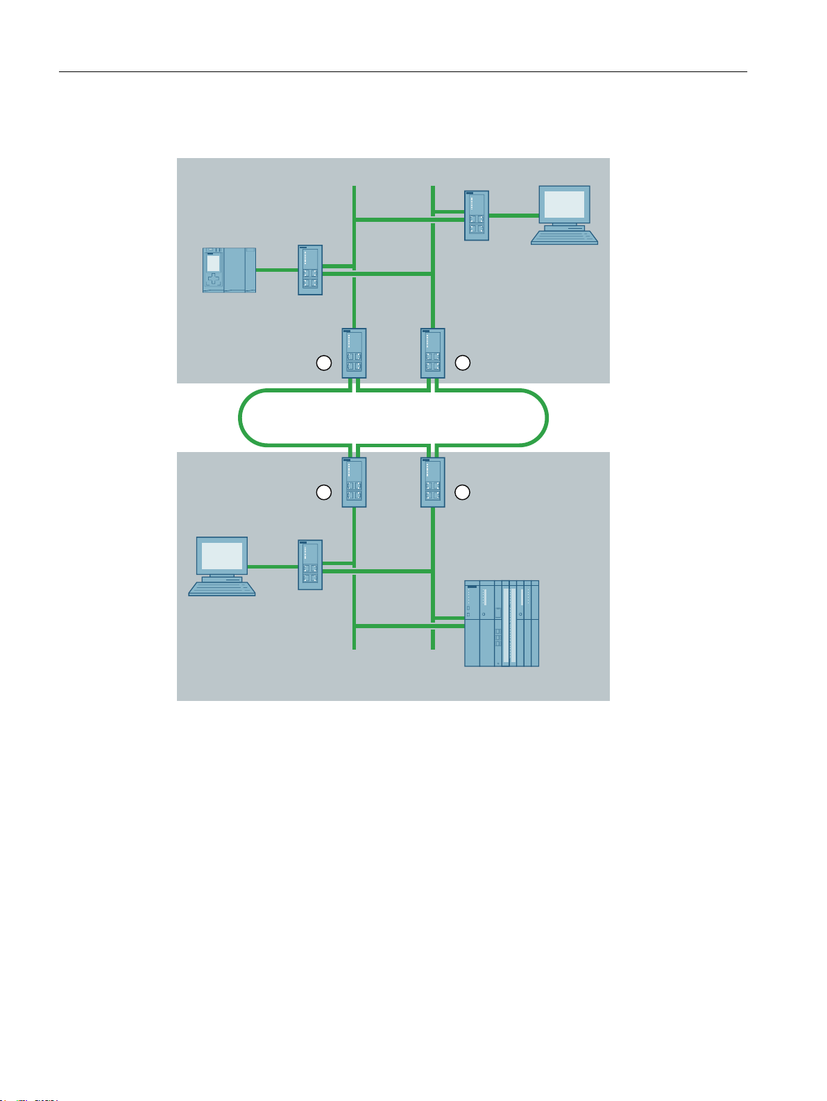
3.3.2 Coupling of two PRP networks via an HSR ring
Settings in WBM
Configuration of the "Coupling Mode" parameter
Figure 3-5 Topology of a coupling of two PRP networks via an HSR ring
You specify the functionality of the devices SCALANCE X204RNA ① to ④ relating to the
coupling of the two PRP networks on the WBM page X200 > Coupling Configuration. You need
to configure the following parameters:
● Coupling Mode
● NetID
Setting for device ① and ③
Redundant HSR PRP coupling, LAN A (The port P2/B is open and must not be used.)
SCALANCE X-200RNA
26 Operating Instructions, 10/2016, C79000-G8976-C342-04

Setting for device ② and ④
Redundant HSR PRP coupling, LAN B (The port P1/A is open and must not be used.)
Configuration of the "NetID" parameter
The network ID of the PRP network is specified with this parameter. The valid range of values
is 1 to 6. The devices SCALANCE X204RNA ① and ② belong to the same PRP network and
you therefore need to set the same value for the NetID parameter for both devices. The same
applies to the devices SCALANCE X204RNA ③ and ④. The last devices named belong
however to a different PRP network and for this reason a different NetID from the devices ①
and ② must be used. For example NetID "5" could be assigned for devices ① und ② and
NetID "6" for devices ③ and ④.
Network topologies and redundancy
3.3 HSR-PRP coupling
SCALANCE X-200RNA
Operating Instructions, 10/2016, C79000-G8976-C342-04 27

Network topologies and redundancy
3.3 HSR-PRP coupling
SCALANCE X-200RNA
28 Operating Instructions, 10/2016, C79000-G8976-C342-04

Descriptions of the products
4
4.1 Overview of the product characteristics
The SCALANCE X204RNA and the SCALANCE X204RNA EEC devices have the same
functionality and differ only in the environmental conditions, the input voltage ranges and the
option of using SFP modules with the SCALANCE X204RNA EEC.
Table 4-1 Overview of the product characteristics
SCALANCE X204RNA SCALANCE X204RNA EEC
SIMATIC environment ● ●
Operating temperature -40 to +60 °C -40 to +70 °C (up to 85 °C max.) 16h)
Diagnostics LED ● ●
24 VDC ● 24 ... 250 VDC / 100 ... 240 VAC - ●
Housing Plastic Metal
Coated printed circuit boards - ● (as of hardware version 3)
2 x 24 VDC ● 100 Base-T, full duplex ● ●
100 Base-T, half duplex - 10 Base-T - SFP interface for SFP modules for HSR
ports
100 Base-FX for HSR ports - ● (using optional SFP modules)
Signaling contact + on-site operation (SE‐
LECT/SET button)
Diagnostics:
via Web Based Management (WBM)
via e-mail notification (SMTP)
via SNMP V1,V2,V3 incl. Traps V2
using SYSLOG server notification
C-PLUG ● ●
IRT capability - SNTP ● ●
Testing to IEC 61850-3 - ●
Testing to IEEE 1613 - ●
- ●
● ●
●
●
●
●
●
●
●
●
SCALANCE X-200RNA
Operating Instructions, 10/2016, C79000-G8976-C342-04 29

Descriptions of the products
4.1 Overview of the product characteristics
Note
PROFINET controllers can communicate with PROFINET devices via the HSR and PRP
network (PROFINET IO and RT). In this case all PROFINET devices (controllers and devices)
must either be capable of HSR or PRP themselves or must be connected to the HSR ring or
to the PRP network via a RedBox.
Within a PRP network (A or B), PROFINET controllers and devices can also communicate with
each other as SANs (PROFINET IO, RT and IRT). A direct PROFINET communication
relationship between DANPs and SANs or DANHs and SANs is not supported.
Table 4-2 Overview of the connection options
Fast Ethernet 100 Mbps SCALANCE X204RNA SCALANCE X204RNA EEC
TP (RJ‑45) 4 2+2
Fiber
multimode
(duplex LC)
Fiber
single mode
(duplex LC)
Fiber
single mode
(duplex LC)
Standard Ethernet ports / PRP ports P1/A, P2/B P1/A, P2/B
HSR ports HSR 1, HSR 2 HSR 1, HSR 2
- 2 x SFP modules SFP991-1
multimode glass up to 3 km
6GK5991-1AD00-8AA0
- 2 x SFP modules SFP991-1LD
monomode glass up to 26 km
6GK5991-1AF00-8AA0
- 2 x SFP modules SFP991-1LH+
monomode glass up to 70 km
6GK5991-1AE00-8AA0
Note
TP connectors of SCALANCE X204RNA EEC
The SCALANCE X204RNA EEC has 2 RJ-45 ports to which you can connect two standard
Ethernet or PRP end devices/network structures without HSR capability.
The SCALANCE X204RNA EEC also has 2 RJ-45 ports and 2 SFP slots. These connection
options communicate with each other; in other words only one connector is ever active. If an
SFP module is inserted, the corresponding RJ-45 jack is disabled.
With these connector options, you can connect the device to an HSR ring.
SCALANCE X-200RNA
30 Operating Instructions, 10/2016, C79000-G8976-C342-04
 Loading...