

Siemens SCALANCE X-200, SCALANCE XF200, X204-2, X204-2TS, X204-2FM Operating Instructions Manual
...
SCALANCE X-200
___________________
___________________
___________________
___________________
___________________
___________________
___________________
___________________
___________________
___________________
___________________
SIMATIC NET
Industrial Ethernet Switches
SCALANCE X-200
Operating Instructions
03/2015
C79000
-G8976-C284-06
Preface
Functions
1
Description of the device
2
Safety notices
3
Installation
4
Connecting up
5
Approvals
6
Technical specifications
7
Dimension drawings
A
Test of mechanical stability
B
Training, Service & Support
C
Siemens AG
Division Digital Factory
Postfach 48 48
90026 NÜRNBERG
GERMANY
C79000-G8976-C284-06
Ⓟ
03/2015 Subject to change
Copyright © Siemens AG 2012 - 2015.
All rights reserved
Legal information
Warning notice system
This manual contains notices you have to observe in order to ensure your personal safety, as well as to prevent
damage to property. The notices referring to your personal safety are highlighted in the manual by a safety alert
symbol, notices referring only to property damage have no safety alert symbol. These notices shown below are
graded according to the degree of danger.
DANGER
indicates that death or severe personal injury will result if proper precautions are not taken.
WARNING
indicates that death or severe personal injury may result if proper precautions are not taken.
CAUTION
indicates that minor personal injury can result if proper precautions are not taken.
NOTICE
indicates that property damage can result if proper precautions are not taken.
If more than one degree of danger is present, the warning notice representing the highest degree of danger will
be used. A notice warning of injury to persons with a safety alert symbol may also include a warning relating to
property damage.
Qualified Personnel
The product/system described in this documentation may be operated only by
personnel qualified
for the specific
task in accordance with the relevant documentation, in particular its warning notices and safety instructions.
Qualified personnel are those who, based on their training and experience, are capable of identifying risks and
avoiding potential hazards when working with these products/systems.
Proper use of Siemens products
Note the following:
WARNING
Siemens products may only be used for the applications described in the catalog and in the relevant technical
documentation. If products and components from other manufacturers are used, these must be recommended
or approved by Siemens. Proper transport, storage, installation, assembly, commissioning, operation and
maintenance are required to ensure that the products operate safely and without any problems. The permissible
ambient conditions must be complied with. The information in the relevant documentation must be observed.
Trademarks
All names identified by ® are registered trademarks of Siemens AG. The remaining trademarks in this publication
may be trademarks whose use by third parties for their own purposes could violate the rights of the owner.
Disclaimer of Liability
We have reviewed the contents of this publication to ensure consistency with the hardware and software
described. Since variance cannot be precluded entirely, we cannot guarantee full consistency. However, the
information in this publication is reviewed regularly and any necessary corrections are included in subsequent
editions.

SCALANCE X-200
Operating Instructions, 03/2015, C79000-G8976-C284-06
3
Preface
Components of the product
The following components are supplied with a
SCALANCE X-200
IE switch:
● One device
● One 2-pin plug-in terminal block
● One 4-pin plug-in terminal block
● One DVD (configuration manual, operating instructions, Primary Setup Tool, GSD file,
SNMP OPC profile)
The following components are supplied with a
SCALANCE X-200
IE switch with the
PRO
supplement:
● One device
● Protective caps for the data interfaces
● Protective caps for the connectors of the power supply
● One protective cap for the signaling contact
● One DVD (configuration manual, operating instructions, Primary Setup Tool, GSD file,
SNMP OPC profile)
Unpacking, checking
WARNING
Do not use any parts that show evidence of damage. If you use damaged parts, there is no
guarantee that the device will function according to the specification.
If you use damaged parts, this can lead to the following problems:
• Injury to persons
• Loss of the approvals
• Violation of the EMC regulations
Use only undamaged parts.
1. Make sure that the package is complete.
2. Check all the parts for transport damage.
If the consignment is incomplete or damaged, contact your supplier or your local Siemens
office.

Preface
SCALANCE X-200
4 Operating Instructions, 03/2015, C79000-G8976-C284-06
Purpose of the Operating Instructions
These operating instructions support you when commissioning networks with the devices of
the product line SCALANCE X-200.
Overview of the technical documentation of the IE Switches X-200
The technical documentation of the X-200 product line is divided into hardware and software
and can be found in the following documents:
●
PH SCALANCE X-200 configuration manual
Software description of the X-200 product line
●
SCALANCE X-200 BA Operating Instructions
Hardware description for all product groups and general information.
You will find the documents here:
● On the data medium that ships with some products:
– Product CD / product DVD
– SIMATIC NET Manual Collection
● On the Internet pages of Siemens Industry Online Support
(http://support.automation.siemens.com/WW/view/en/33118791/133300
).
Validity of the Operating Instructions
These operating instructions are valid for the following devices:
SCALANCE X200 and SCALANCE XF200
Product name:
Order number:
X204-2 6GK5 204-2BB10-2AA3
X204-2TS
6GK5 204-2BB10-2CA2
X204-2FM
6GK5 204-2BB11-2AA3
X204-2LD
6GK5 204-2BC10-2AA3
X204-2LD TS
6GK5 204-2BC10-2CA2
X206-1
6GK5 206-1BB10-2AA3
X206-1LD
6GK5 206-1BC10-2AA3
X208
6GK5 208-0BA10-2AA3
X208PRO
6GK5 208-0HA10-2AA6
X212-2
6GK5 212-2BB00-2AA3
X212-2LD
6GK5 212-2BC00-2AA3
X216
6GK5 216-0BA00-2AA3
X224
6GK5 224-0BA00-2AA3
Flat design:
XF204
6GK5 204-0BA00-2AF2
XF204-2
6GK5 204-2BC00-2AF2

Preface
SCALANCE X-200
Operating Instructions, 03/2015, C79000-G8976-C284-06
5
SCALANCE X200 and SCALANCE XF200
XF206-1
6GK5 206-1BC00-2AF2
XF208 6GK5 208-0BA00-2AF2
SCALANCE X200IRT and XF200IRT
Product name:
Order number:
X200-4P IRT 6GK5 200-4AH00-2BA3
X201-3P IRT
6GK5 201-3BH00-2BA3
X201-3P IRT PRO
6GK5 201-3JR00-2BA6
X202-2IRT
6GK5 202-2BB00-2BA3
X202-2P IRT
6GK5 202-2BH00-2BA3
X202-2P IRT PRO
6GK5 202-2JR00-2BA6
X204IRT
6GK5 204-0BA00-2BA3
X204IRT PRO
6GK5 204-0JA00-2BA6
Flat design:
XF204IRT
6GK5 204-0BA00-2BF2
Purpose
The SCALANCE X-200 devices are switches for setting up Ethernet networks for industrial
applications.
Restricted area of application according to Hazardous Locations (HazLoc)
The devices are only suitable for use in the following areas:
● In areas according to Class I, Division 2, Groups A, B, C and D and in areas without
explosive atmospheres.
● In areas according to Class I, Zone 2 Groups IIC and in areas without explosive
atmospheres.
Names of the devices in these operating instructions
Unless mentioned otherwise, the descriptions in these operating instructions refer to all
devices of the SCALANCE X-200 product line named above in the section on Validity.
In the remainder of the instructions, these will also be referred to as
IE switches
or also
simply as
X-200
.

Preface
SCALANCE X-200
6 Operating Instructions, 03/2015, C79000-G8976-C284-06
Further documentation
In the system manuals "Industrial Ethernet / PROFINET Industrial Ethernet" and "Industrial
Ethernet / PROFINET passive network components", you will find information on other
SIMATIC NET products that you can operate along with the devices of this product line in an
Industrial Ethernet network.
You will find the system manuals on the Internet pages of Siemens Industry Online Support
under the following entry IDs:
● 27069465 (http://support.automation.siemens.com/WW/view/en/27069465
)
Industrial Ethernet / PROFINET Industrial Ethernet System Manual
● 84922825 (http://support.automation.siemens.com/WW/view/en/84922825)
Industrial Ethernet / PROFINET - Passive network components System Manual
Finding information
To help orientation, there is not only a table of contents but also an Index in the Appendix.
The SIMATIC NET Glossary also provides additional help, see below.
Audience
These operating instructions are intended for persons involved in commissioning networks in
which IE switches are used.
SIMATIC NET Selection Tool
The SIMATIC NET selection tool supports you when selecting Industrial Ethernet switches
and components for Industrial Wireless Communication. You will find current information on
the Product Support pages under the following entry ID:
39134641 (http://support.automation.siemens.com/WW/view/en/39134641
)

Preface
SCALANCE X-200
Operating Instructions, 03/2015, C79000-G8976-C284-06
7
Where to find Siemens documentation
● Article numbers
You will find the article numbers for the Siemens products of relevance here in the
following catalogs:
– SIMATIC NET - Industrial Communication / Industrial Identification, catalog IK PI
– SIMATIC - Products for Totally Integrated Automation and Micro Automation, catalog
ST 70
You can request the catalogs and additional information from your Siemens
representative. You will also find the product information in the Siemens Industry Mall at
the following address:
(https://mall.industry.siemens.com
)
● Manuals on the Internet
You will find SIMATIC NET manuals on the Internet pages of Siemens Industry Online
Support:
Link to Customer Support (http://support.automation.siemens.com/WW/view/en
)
Enter the entry ID of the relevant manual as the search item. The entry ID is specified in
the references.
As an alternative, you will find the SIMATIC NET documentation on the pages of Product
Support:
10805878 (http://support.automation.siemens.com/WW/view/en/10805878
)
Go to the required product group and make the following settings:
"Entry list" tab, Entry type "Manuals / Operating Instructions"
● Manuals on the data medium
You will often find manuals of SIMATIC NET products on the data medium that ships with
many of the SIMATIC NET products.
Security information
Siemens provides products and solutions with industrial security functions that support the
secure operation of plants, solutions, machines, equipment and/or networks. They are
important components in a holistic industrial security concept. With this in mind, Siemens’
products and solutions undergo continuous development. Siemens recommends strongly
that you regularly check for product updates.
For the secure operation of Siemens products and solutions, it is necessary to take suitable
preventive action (e.g. cell protection concept) and integrate each component into a holistic,
state-of-the-art industrial security concept. Third-party products that may be in use should
also be considered. For more information about industrial security, visit
http://www.siemens.com/industrialsecurity.
To stay informed about product updates as they occur, sign up for a product-specific
newsletter. For more information, visit http://support.automation.siemens.com.

Preface
SCALANCE X-200
8 Operating Instructions, 03/2015, C79000-G8976-C284-06
SIMATIC NET glossary
Explanations of many of the specialist terms used in this documentation can be found in the
SIMATIC NET glossary.
You will find the SIMATIC NET glossary here:
● SIMATIC NET Manual Collection or product DVD
The DVD ships with certain SIMATIC NET products.
● On the Internet under the following entry ID:
50305045 (http://support.automation.siemens.com/WW/view/en/50305045
)
Trademarks
The following and possibly other names not identified by the registered trademark sign ® are
registered trademarks of Siemens AG:
SIMATIC NET, SCALANCE, C-PLUG, OLM

SCALANCE X-200
Operating Instructions, 03/2015, C79000-G8976-C284-06
9
Table of contents
Preface ...................................................................................................................................................... 3
1 Functions ................................................................................................................................................. 11
2 Description of the device ......................................................................................................................... 15
2.1 Device views ........................................................................................................................... 15
2.2 The LEDs ................................................................................................................................ 17
2.2.1 LED display when the device starts up ................................................................................... 17
2.2.2 Power LED "L" (green/yellow LED) ........................................................................................ 17
2.2.3 Fault LED "F" (yellow/red LED) .............................................................................................. 18
2.2.4 Redundancy manager LED "RM" (green LED) ...................................................................... 18
2.2.5 Standby LED "RM" (yellow LED) ............................................................................................ 19
2.2.6 Port LEDs "P" (green/yellow LEDs) ........................................................................................ 20
2.2.7 Diagnostics LEDs for optical connectors "F" (yellow LED) ..................................................... 20
2.2.8 Show Location ........................................................................................................................ 20
2.3 The SET button ....................................................................................................................... 21
2.4 The C-PLUG ........................................................................................................................... 22
3 Safety notices .......................................................................................................................................... 27
3.1 Safety notices in general ........................................................................................................ 27
3.2 Safety notices for hazardous areas ........................................................................................ 29
3.3 Security recommendations ..................................................................................................... 30
4 Installation ............................................................................................................................................... 33
4.1 Safety notices for installation .................................................................................................. 33
4.2 Installation options .................................................................................................................. 36
4.3 Installation on a DIN rail .......................................................................................................... 37
4.4 Installation on a standard rail .................................................................................................. 38
4.5 Wall mounting ......................................................................................................................... 39
5 Connecting up ......................................................................................................................................... 41
5.1 Safety when connecting up ..................................................................................................... 41
5.2 Power supply .......................................................................................................................... 44
5.2.1 Power supply via terminal block ............................................................................................. 44
5.2.2 Supply for X208PRO .............................................................................................................. 45
5.2.3 Supply for IRT-PRO devices ................................................................................................... 45
5.3 Grounding ............................................................................................................................... 48
5.4 Signaling contact ..................................................................................................................... 49
5.5 Attachment to Industrial Ethernet ........................................................................................... 51
5.5.1 Electrical connections ............................................................................................................. 51

Table of contents
SCALANCE X-200
10 Operating Instructions, 03/2015, C79000-G8976-C284-06
5.5.1.1 Electrical attachments to Industrial Ethernet ......................................................................... 51
5.5.1.2 Electrical connectors of the X208PRO .................................................................................. 53
5.5.2 Optical attachments to Industrial Ethernet ............................................................................. 55
5.5.2.1 Multimode fiber-optic cable .................................................................................................... 55
5.5.2.2 Single mode fiber-optic cable ................................................................................................. 56
5.5.2.3 POF and PCF cables ............................................................................................................. 56
5.5.3 Push-pull connector for IRT-PRO devices ............................................................................. 58
6 Approvals ................................................................................................................................................. 59
7 Technical specifications ........................................................................................................................... 67
A Dimension drawings ................................................................................................................................ 77
B Test of mechanical stability ...................................................................................................................... 83
C Training, Service & Support ..................................................................................................................... 85
Index ........................................................................................................................................................ 87

SCALANCE X-200
Operating Instructions, 03/2015, C79000-G8976-C284-06
11
1
Functions of the X-200 IE Switches
The X-200 IE switches are ideally suited for setting up Industrial Ethernet networks in bus,
star and ring structures with transmission rates of 10/100 Mbps. All X-200 switches operate
in the SIMATIC environment.
Hardware properties:
● X devices have a rugged metal housing and can be installed on a DIN rail, a standard rail
or directly on a wall.
● XF devices have a plastic housing and a flat design. They are suitable for installation on a
DIN rail.
● Redundant power supply, 2 x 24 VDC (exception: IRT-PRO devices)
● Diagnostics LED
● Signaling contact
● SET button for local configuration of the signaling contact
● Slot for C-PLUG
● Reliable plug-in connections thanks to rugged device connectors suitable for industry in
conjunction with PROFINET-compliant FastConnect plugs.
● TS devices meet the railway standard EN 50155
Software properties:
● PROFINET Diagnostics
● Topology support (LLDP)
● CLI - Command Line Interface / Telnet
● WBM - Web Based Management
● Configuration with STEP 7
● SNMP
● Ring redundancy including redundancy manager
● Passive Listening
● FM devices support the Fiber Monitoring Protocol and allow the monitoring of optical line
sections.

Functions
SCALANCE X-200
12 Operating Instructions, 03/2015, C79000-G8976-C284-06
Special features of the X-200IRT IE switches
The IRT variants were designed specifically for setting up Industrial Ethernet networks with
isochronous/clock synchronous real-time communication. In addition to the properties named
above, the IRT switches also provide the following functions:
● IRT communication based on the combination of the switching methods cut through and
store and forward.
● Fast media redundancy thanks to an integrated redundancy manager for Fast Ethernet.
● Standby redundancy
Special features of the PRO variants
The devices with the "PRO" supplement are designed with degree of protection IP65/IP67
for use outside a cabinet.
Frame delay times
The number of IE Switches X-200 connected in a line influences the frame delay.
Note
Frame delay time with X-200 without IRT
When a frame passes through X
-200 IE switches, it is delayed by the Store&Forward
fun
ction of the X-200 IE switches.
•
With a 64 byte frame length by approx. 10 microseconds (at 100 Mbps).
•
With a 1500 byte frame length by approx. 130 microseconds (at 100 Mbps).
This means that the more IE
Switch X-200 devices the frame passes through, the longer the
frame delay.
Note
Frame delay time with X-200 with IRT
The more X
-200IRT IE switches a frame runs through, the higher the frame delay. By using
the "cut through" switching mechanism, the X
-200IRT IE switches are ideal to meet the real-
time requirements of PROFINET.
Cut through is, however, not possible:
•
Between a port set to 10 Mbps and a port set to 100 Mbps.
•
When two packets are to be sent at the same time on one port.
In this case, an X-200 IE switch changes to Store&Forward and the delay increases.
Functions
SCALANCE X-200
Operating Instructions, 03/2015, C79000-G8976-C284-06
13
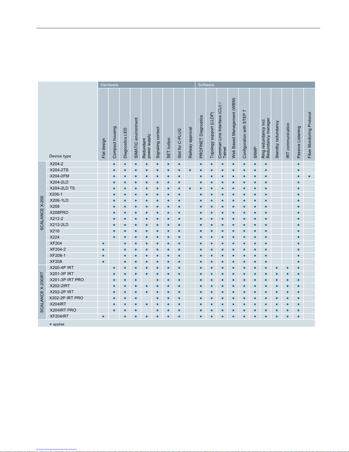
Overview of the functions
The following table shows the hardware and software properties for each product variant of
the X-200 switches in detail:
Number of electrical and optical connectors in the product name
The number before the hyphen in the product name indicates the number of electrical
connectors. The number following the hyphen indicates the number of optical connectors of
the device. For example, the switch X212-2 has twelve electrical and two optical connectors.

Functions
SCALANCE X-200
14 Operating Instructions, 03/2015, C79000-G8976-C284-06
SCALANCE X-200
Operating Instructions, 03/2015, C79000-G8976-C284-06
15
2
2.1
Device views
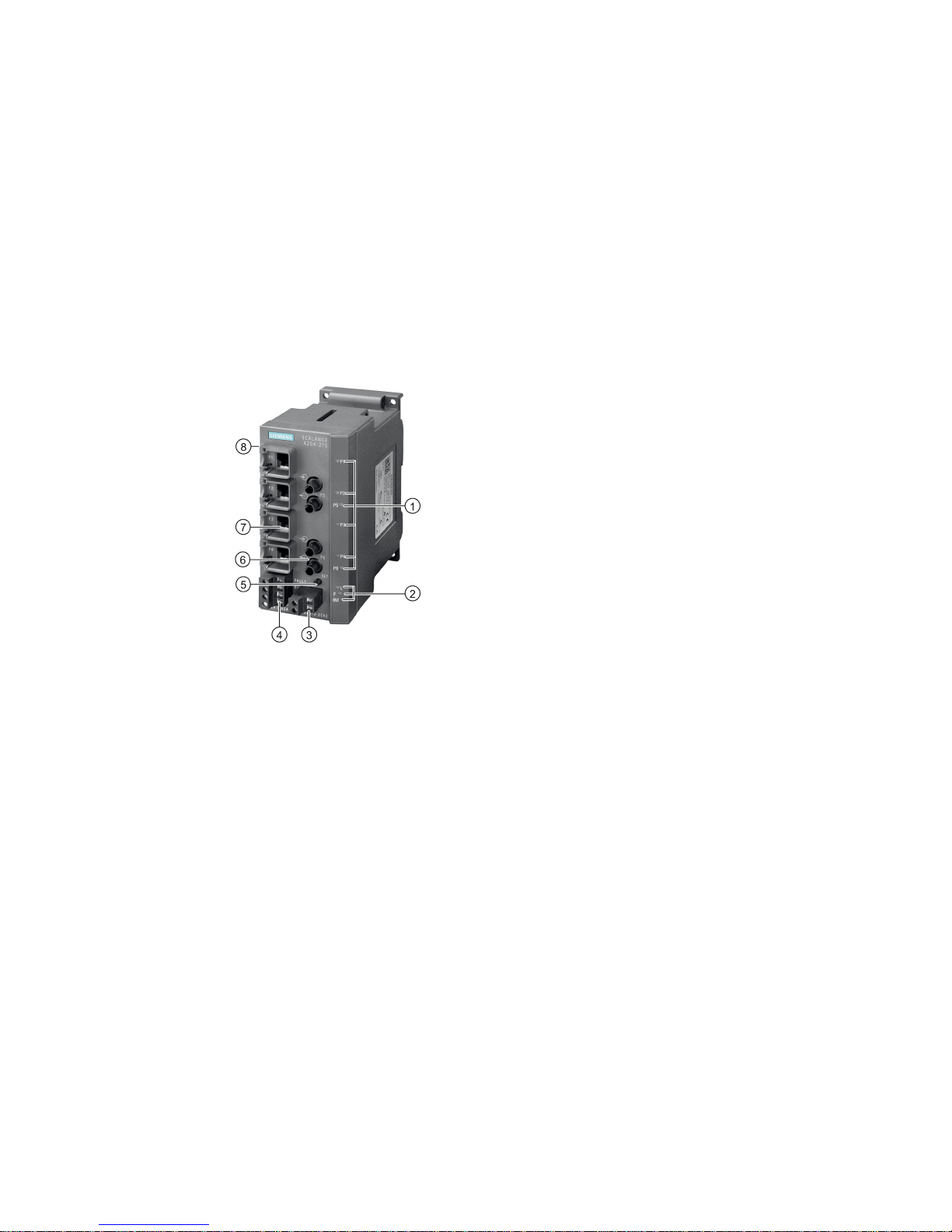
Device view based on the example of an X204-2TS
The following figure describes the individual components of an IE switch X200.
1
LEDs for attachments to Industrial Ethernet
2 LEDs
•
L: Power LED, power supply
•
F: Fault LED
•
RM: Redundancy manager or standby
3
Connector for signaling contact
4
Connector for power supply
5
SET button
6
Optical attachment to Industrial Ethernet
7
Electrical attachment to Industrial Ethernet
8 (on rear of device, not shown in figure:) Slot for C
-
PLUG
Description of the device
2.1 Device views
SCALANCE X-200
16 Operating Instructions, 03/2015, C79000-G8976-C284-06
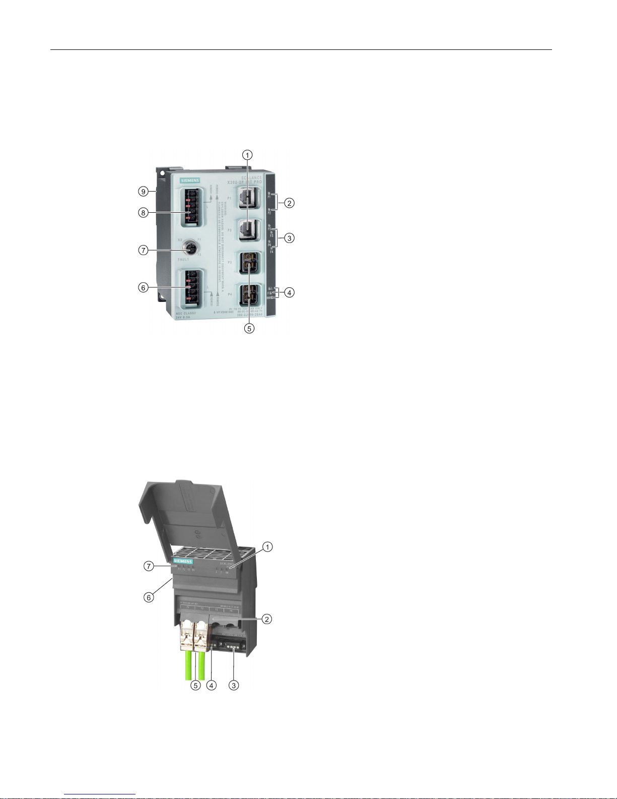
Device view based on the example of an X202-2P IRT PRO
The following figure describes the individual components of a PRO version of an IE switch X-
200.
1
Electrical attachments to Industrial Ethernet
2 LEDs for electrical connectors
3 LEDs for optical connectors with diagnostics
LEDs
4 LEDs
•
L: Power LED, power supply
•
F: Fault LED
•
RM:
– green = redundancy manager
– yellow = standby indicator
5
Optical attachments to Industrial Ethernet
6 Connector for the power supply (supplied with
L1, additionally looped through to L2)
7
Connector for signaling contact
8 Power supply for further devices (looped
through from L1 to L2)
9 (on rear of device, not shown in figure): Slot for
the C-PLUG and SET button
Device view based on the example of an XF204
The following figure describes the individual components of an IE switch X-200, flat design.
1 LEDs
•
L: Power LED, power supply
•
F: Fault LED
•
RM: Redundancy manager
2
Attachments to Industrial Ethernet
3
Connector for power supply
4
Connector for signaling contact
5 (behind the connectors, not shown in figure:)
SET button
6 (on side of device, not shown in figure:) Slot for
C-PLUG
7 LEDs for attachments to Industrial Ethernet

Description of the device
2.2 The LEDs
SCALANCE X-200
Operating Instructions, 03/2015, C79000-G8976-C284-06
17
2.2
The LEDs
2.2.1
LED display when the device starts up
When the X-200 starts up, the LEDs light up in the following sequence:
● The green power LED lights up immediately after turning on the device.
● The LEDs of the Ethernet connectors light up for approximately 6 seconds.
● When the Ethernet LEDs go off, the red fault LED is lit for approximately 20 seconds.
● Following this, after approximately 2 seconds the correct link status is displayed.
The X-200 is now ready for operation.
2.2.2
Power LED "L" (green/yellow LED)
The power LED shows the status of the power supply on the X-200 IE switch. The power
LED can light up either green or yellow. The meanings of the display are as follows:
LED color
LED status
Meaning
Green
Lit
Both power supplies are connected; in other words, redundant power supply.
Yellow Lit Only one power supply is connected.
- Off No power supply is connected or the voltage is < 14 VDC or with TS devices < 8
VDC.
Note
The following devices do not have a redundant power supply:
•
X201-3P IRT PRO
•
X202-2P IRT PRO
•
X204IRT PRO

Description of the device
2.2 The LEDs
SCALANCE X-200
18 Operating Instructions, 03/2015, C79000-G8976-C284-06
2.2.3
Fault LED "F" (yellow/red LED)
The fault LED indicates a fault/error on the X-200. If the X-200 detects an error, the signaling
contact is opened at the same time assuming that the response of the signaling contact was
not configured differently.
The meanings of the fault LED display are as follows:
LED color
LED status
Meaning
Yellow Lit The LED can only adopt this status with FM devices.
Check the received power or the loss of power on optical connections. If necessary,
replace the parts.
Red Lit The fault LED lighting up can have the following meanings:
• Link down event on a monitored port
• Loss of the power supply
• C-PLUG error
• Device is in PROFINET mode:
– There is no connection to the controller.
– There is a connection to the controller. A configured diagnostics interrupt is
also pending, for example power fail interrupt, C-PLUG interrupt etc.
• Redundancy manager connected through
• Switchover of standby connection
• A defined value was undershot in a monitored optical connection.
• A loop was detected.
• Device startup. The LED lights up for approximately 20 seconds.
Red Flashing Internal error detected. Notify maintenance personnel. If necessary, send the device
in for repair.
-
Off
No error detected.
2.2.4
Redundancy manager LED "RM" (green LED)
The green LED shows the following statuses of the X-200:
LED color
LED status
Meaning
Green Lit The device is operating in the role of redundancy manager. The ring is operating free
of errors. The monitoring is enabled.
Green Flashing The device is operating in the role of redundancy manager. An interruption was de-
tected in the ring. The device has switched through.
-
Off
The device is not operating in the role of redundancy manager.

Description of the device
2.2 The LEDs
SCALANCE X-200
Operating Instructions, 03/2015, C79000-G8976-C284-06
19
Note
This LED labeled on the device with "RM" has a dual function. The color of the display
changes depending on the function:
•
If the LED is lit green, the redundancy manager function is indicated.
•
If the LED is lit yellow, the standby function is indicated.
In
Web Based Management (WBM), the LED is labeled differently depending on the
function:
•
The redundancy manager function (as shipped) is labeled "RM".
•
The standby function is labeled "SB" in the WBM.
2.2.5
Standby LED "RM" (yellow LED)
You will find the standby LED only on devices with the IRT function.
Note
This LED labeled on the device with "RM" has a dual function. The color of the display
changes depending on the function:
•
If the LED is lit green, the redundancy manager function is indicated.
•
If the LED is lit yellow, the standby function is indicated.
In
Web Based Management (WBM), the LED is labeled differently depending on the
function:
•
The redundancy manager function (as shipped) is labeled "RM".
•
The standby function is labeled "SB" in the WBM.
The yellow LED indicates the following statuses of the X-200IRT:
LED color
LED status
Meaning
Yellow
Lit
The standby function is activated, the switch is in active mode.
Yellow
Flashes slowly
The standby function is activated, the switch is in passive mode.
Yellow
Flashes quickly
Standby partner lost.
-
Off
The standby function is not activated.

Description of the device
2.2 The LEDs
SCALANCE X-200
20 Operating Instructions, 03/2015, C79000-G8976-C284-06
2.2.6
Port LEDs "P" (green/yellow LEDs)
The LEDs of the Ethernet connectors can be lit green or yellow. The meanings of the display
are as follows:
LED color
LED status
Meaning
Green
Lit
Link exists, no data reception
Yellow Lit Link exists, data being received
Device startup. The LED lights up for approximately 6 seconds.
Yellow
Flashing
Setting or display of the fault mask
The following statuses of the port LEDs do not exist on devices with the IRT function:
LED color
LED status
Meaning
Green flashes
once per period
Link exists and port in "blocking" status.
In this status, the port only receives management data (no user data).
Green flashes
three times per
period
Link exists and port is deactivated by the management.
In this status, no data is sent or received via the port.
Green flashes
four times per
period
Port exists and is in the "monitor port" status.
In this status, the data traffic of another port is mirrored to this port.
2.2.7
Diagnostics LEDs for optical connectors "F" (yellow LED)
You will find the diagnostics LEDs only on the devices with the IRT function.
The status of the optical connectors is indicated by an additional yellow LED per connector.
The LEDs signal the following statuses:
LED color
LED status
Meaning
Yellow Lit Check the plug-in connection and the quality of the fiber-optic cable. If necessary,
replace the parts.
- Off Relevant only if the link exists. The existing link power margin is adequate for error-
free operation.
2.2.8
Show Location
Localizing an IE Switches X-200
To identify an IE Switch X-200 locally and with certainty, you can use the "show location"
function on a programming device to select the node over the network and make it flash.
This can be used, for example, when assigning addresses to make sure that the correct
node receives the address. All port LEDs of the addressed node flash green at 2 Hz.
With the Primary Setup Tool (PST) V3.0 or higher, you can trigger this function with "Module
\ Flash".
Description of the device
2.3 The SET button
SCALANCE X-200
Operating Instructions, 03/2015, C79000-G8976-C284-06
21
2.3
The SET button
Function of the SET button
With the SET button, you can change various settings of the device. The changed settings
remain after cycling power to the device.
Different settings are made depending on how long you hold down the SET button, as
described in the following table:
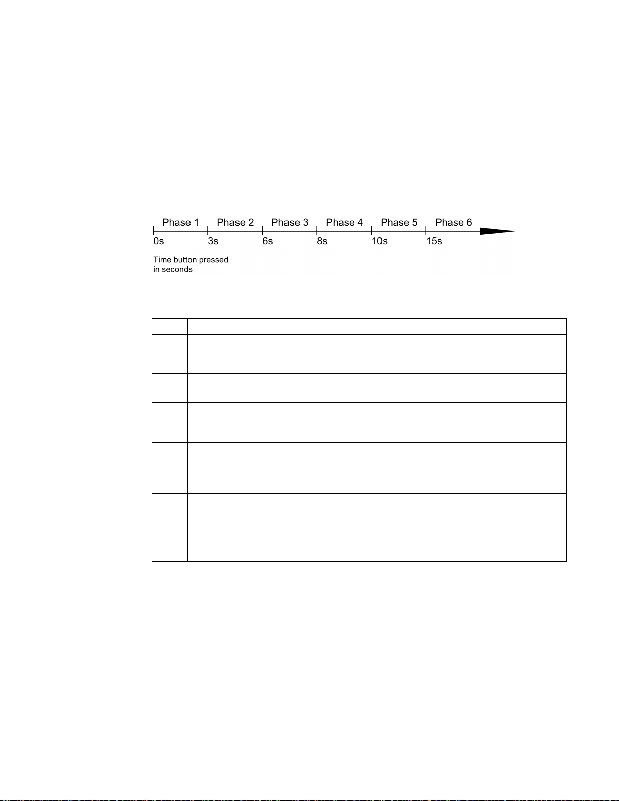
Figure 2-1 Phases for changing settings using the SET button
Phase
Description
1 The currently set fault mask is displayed. If no fault mask has been set, all ports flash one
after the other.
If you release the button in phase 1, this has no effect.
2 The LEDs of the ports at which there is currently a link flash at 2.5 Hz.
If you release the button in phase 2, this has no effect.
3 The LEDs of the ports at which there is currently a link and the LEDs of the connected pow-
er supply are lit permanently.
If you release the button in phase 3, the fault mask corresponding to the lit LEDs is adopted.
4 The RM LED flashes.
If you release the button in phase 4, the redundancy manager is deactivated. The redundancy function remains enabled. The device changes to "Automatic Redundancy Detect"
mode.
5 The RM LED is lit permanently.
If you release the button in phase 5, the redundancy function is activated and the device is
configured as HRP manager.
6 All LEDs flash.
The device is reset to the factory defaults.

Description of the device
2.4 The C-PLUG
SCALANCE X-200
22 Operating Instructions, 03/2015, C79000-G8976-C284-06
2.4
The C-PLUG
Area of application
The C-PLUG is an exchangeable medium for storage of the configuration and project
engineering data of the basic device. This means that the configuration data remains
available if the basic device is replaced.
How it works
Power is supplied by the basic device. The C-PLUG retains all data permanently when the
power is turned off.
If an empty C-PLUG (factory settings) is inserted, all configuration data of an IE
Switch X-200 is saved to it when the device starts up. Changes to the configuration during
operation are also saved on the C-PLUG without any operator intervention being necessary.
If a C-PLUG is inserted, the configuration stored internally on the basic device is no longer
changed. Al changes made to the configuration during ongoing operation are only stored on
the C-PLUG.
A basic device with an inserted C-PLUG automatically uses the configuration data of the
C-PLUG when it starts up. This is, however, only possible when the data was written by a
compatible device type.
This allows fast and simple replacement of the basic device. If a device is replaced, the CPLUG is taken from the failed component and inserted in the replacement device. The first
time it is started up, the replacement device has the same configuration as the failed device
except for the MAC address set by the vendor.

Description of the device
2.4 The C-PLUG
SCALANCE X-200
Operating Instructions, 03/2015, C79000-G8976-C284-06
23
Compatible devices
As a general rule, the data on the C-PLUG is only compatible with devices having an
identical order number and the same device name.
The device combinations shown in the following table are exceptions. With these devices,
the exchange of the C-PLUG is possible in one direction.
Device type
C-PLUG created by device with
order number
Compatible with device with
order number
X204-2
6GK5 204-2BB00-2AA3
6GK5 204-2BB10-2AA3
X204-2LD 6GK5 204-2BC00-2AA3 6GK5 204-2BC10-2AA3
X206-1
6GK5 206-1BB00-2AA3
6GK5 206-1BB10-2AA3
X206-1LD
6GK5 206-1BC00-2AA3
6GK5 206-1BC10-2AA3
X208
6GK5 208-0BA00-2AA3
6GK5 208-0BA10-2AA3
X208PRO
6GK5 208-0HA00-2AA6
6GK5 208-0HA10-2AA6
Note
Combinations other than those shown in the table are not compatible with each other.
Note
If you insert a C
-PLUG in a compatible device, the system name of the original device is
entered both in the system name as well as in the PROFINET IO device name of the
compatible device.
Using a previously written C-PLUG
If you want to insert a C-PLUG that has already been used and written to into a new
differently configured X-200 IE switch, you will first need to delete the existing data on the CPLUG. You will find information about this in the configuration manual of the SCALANCE X200 in the section on the WBM menu items.
Note
The X
-200 IE switches normally start up with the configuration of the C-
PLUG, assuming this
was written to by a compatible device type. If the C
-PLUG was written to by an incompatible
device type, the basic device will not start up fully and signals an error. The WBM menu
"System C
-PLUG" is displayed automatically. Here, use the "Modify C-PLUG" function to
specify whether or not the device operates
with a C-PLUG.
If you operate a device with a C
-PLUG, the C-PLUG can either be initialized with the factory
settings or with the settings stored internally on the device.
Description of the device
2.4 The C-PLUG
SCALANCE X-200
24 Operating Instructions, 03/2015, C79000-G8976-C284-06
Diagnostics
The following events are signaled by the diagnostics mechanisms of the X-200, such as
LEDs, WBM etc.:
● Inserting a C-PLUG that contains the configuration of an incompatible device type.
● The accidental removal of a C-PLUG
● General malfunctions of the C-PLUG.
The C-PLUG does not ship with the product
The C-PLUG is not supplied with the X-200 IE switch. It is an optional accessory available
under the following order number: 6GK1 900-0AB00.
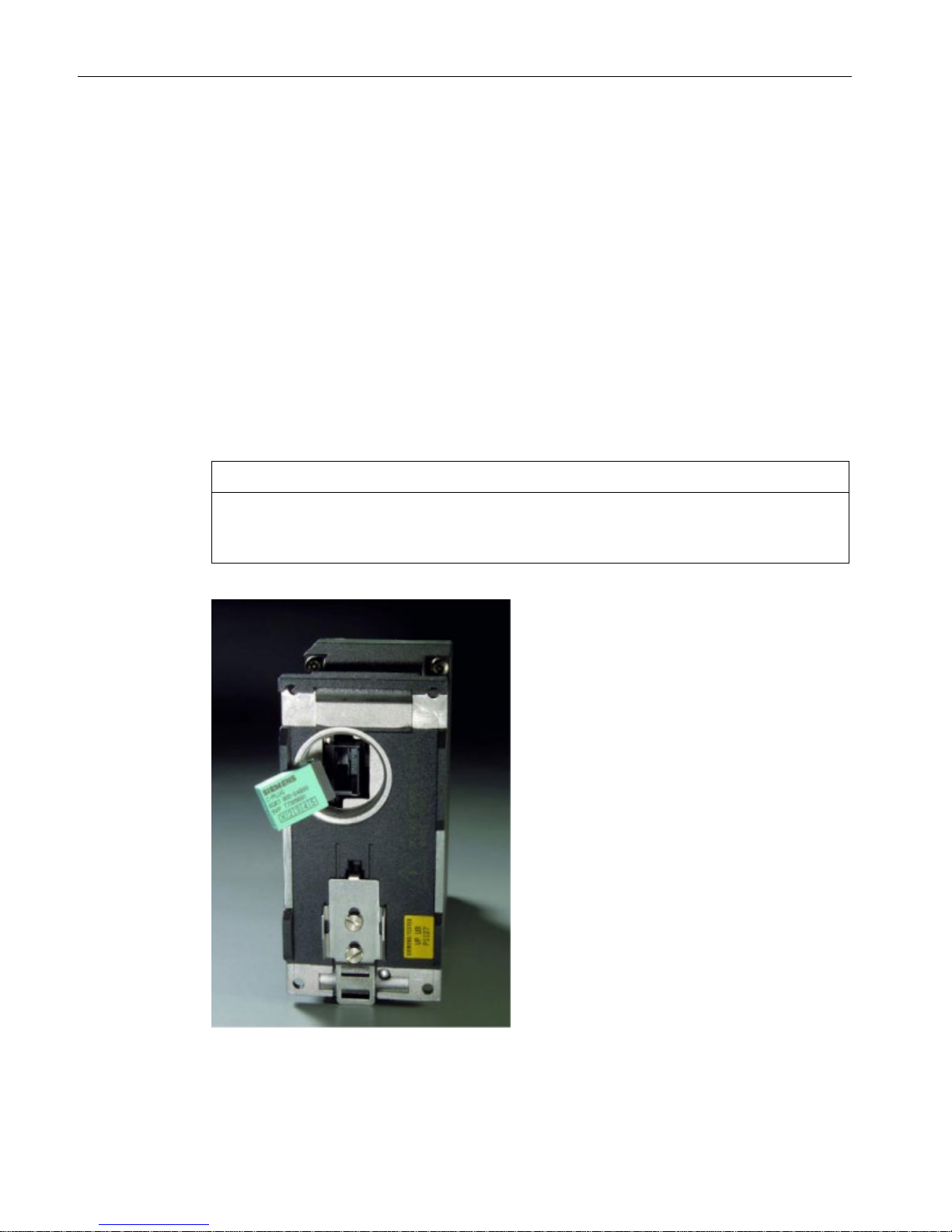
Inserting in the slot
NOTICE
•
Insert and remove the C-PLUG only when power is off.
•
In a device with a varnished printed circuit board, you may only use a C-PLUG with a
varnished board.
Figure 2-2 C-PLUG and slot

Description of the device
2.4 The C-PLUG
SCALANCE X-200
Operating Instructions, 03/2015, C79000-G8976-C284-06
25
The slot for the C-PLUG is located as follows:
● On the IE Switch X-200 on the back of the device.
● On the IE Switch XF-200 on the left hand side of the device.
Follow the steps below to insert the C-PLUG:
1. Remove the screw cover.
2. Insert the C-PLUG in the slot.
3. Close the slot with the screw cover.
Removing the C-PLUG
It is only necessary to remove the C-PLUG if the IE Switch X-200 develops a fault.
You can lever the C-PLUG out of the slot carefully using flat pliers, tweezers, or a small
screwdriver.
If no C-PLUG is inserted in the device, when the device restarts, an error message is output
in Web Based Management and in the Command Line Interface. In this case, you will need
to set the device to operation without C-PLUG. For further information, refer to the section
"System C-PLUG" in the section on the WBM menu in the configuration manual.

Description of the device
2.4 The C-PLUG
SCALANCE X-200
26 Operating Instructions, 03/2015, C79000-G8976-C284-06

SCALANCE X-200
Operating Instructions, 03/2015, C79000-G8976-C284-06
27
3
3.1
Safety notices in general
Note the following safety notices. These relate to the entire working life of the device.
WARNING
Do not use any parts that show evidence of damage
If you use damaged parts, there is no guarantee that the device will function according to
the specification.
If you use damaged parts, this can lead to the following problems:
• Injury to persons
• Loss of the approvals
• Violation of the EMC regulations
• Damage to the device and other components
Use only undamaged parts.
Installation guidelines
The product meets the requirements if you adhere to the installation and safety notices
contained in this documentation and in the following documentation when installing and
operating the product.
Current documentation on the Internet
The current descriptions of the currently available products can be found on the Product
Support pages under the entry IDs below:
● Configuration manual SIMATIC NET PH SCALANCE X-200
63203259 (http://support.automation.siemens.com/WW/view/en/63203259
)
● System manual SIMATIC NET Industrial Ethernet Network Manual
27069465 (http://support.automation.siemens.com/WW/view/en/27069465
)
● Configuration manual EMC Installation Guidelines
60612658 (http://support.automation.siemens.com/WW/view/en/60612658
)
Electrostatic discharge
To protect the product process from electrostatic discharge, personnel must first discharge
any electrostatic charge from their body before touching the product.
 Loading...