

Siemens SCALANCE X101-1, SCALANCE X101-1POF, SCALANCE X101-1FL, SCALANCE X101-1LD Commissioning Manual

SIMATIC NET
Industrial Ethernet
SCALANCE X101-1
Preface
Introduction
Network Topologies
Product Characteristics
Installation and Maintenance
1
2
3
4
5
SCALANCE X101-1FL
SCALANCE X101-1LD
SCALANCE X101-1POF
Commissioning Manual
Notes on the CE Mark
References
Dimension Drawings
6
7
8
07/2008
A2B00051521A

Safety Guidelines
This manual contains notices which you should observe to ensure your own personal safety as well as to avoid
property damage. The notices referring to your personal safety are highlighted in the manual by a safety alert
symbol, notices referring to property damage only have no safety alert symbol. Depending on the danger level,
the notices are displayed in descending order as follows.
Danger
indicates that death or severe personal injury
Warning
indicates that death or severe personal injury
Caution
with safety alert symbol indicates that minor personal injury can result if proper precautions are not taken.
will result if proper precautions are not taken.
may result if proper precautions are not taken.
Caution
without safety alert symbol indicates that property damage can result if proper precautions are not taken.
Notice
indicates that an unintended result or situation can occur if the corresponding information is not taken into
account.
When several danger levels apply, the notices of the highest level (lower number) are always displayed. If a
notice refers to personal damages with the safety alert symbol, then another notice may be added warning of
property damage.
Qualified Personnel
The device/system may only be set up and operated in conjunction with this documentation. Only qualified
personnel should be allowed to install and work on the equipment. Only qualified personnel should be allowed to
install and work on the equipment. Qualified persons are defined as persons who are authorized to commission,
to earth, and to tag circuits, equipment and systems in accordance with established safety practices and
standards.
Intended Use
Please note the following:
Warning
This device and its components may only be used for the applications described in the catalog or technical
description, and only in connection with devices or components from other manufacturers approved or
recommended by Siemens. This product can only function correctly and safely if it is transported, stored, set up
and installed correctly, and operated and maintained as recommended.
Trademarks
All designations marked with ® are registered trademarks of Siemens AG. Other designations in this
documentation might be trademarks which, if used by third parties for their purposes, might infringe upon the
rights of the proprietors.
Copyright Siemens AG 2008. All rights reserved.
Reproduction, transmission or use of this document or its contents is not permitted without
express written authority. Offenders will be liable for damages. All rights, including rights
created by patent grant or registration of a utility model or design, are reserved.
Siemens AG
Automation and Drives Group
P.O. Box 4848, D-90327 Nuremberg (Germany)
Siemens Aktiengesellschaft A2B00051521A
Disclaimer of Liability
We have checked the contents of this manual for agreement with the hardware and
software described. Since deviations cannot be precluded entirely, we cannot guarantee
full agreement. However, the data in the manual are reviewed regularly, and any
necessary corrections will be included in subsequent editions.
Siemens AG 2008
Technical data subject to change

Table of Contents
1 Preface ................................................................................................................................................... 1-1
1.1 Preface....................................................................................................................................... 1-1
2 Introduction............................................................................................................................................. 2-1
2.1 Introduction ................................................................................................................................ 2-1
3 Network Topologies ................................................................................................................................ 3-1
3.1 Network Topologies ................................................................................................................... 3-1
3.2 Coupling of Network Segments ................................................................................................. 3-4
4 Product Characteristics........................................................................................................................... 4-1
4.1 Overview .................................................................................................................................... 4-1
4.2 SCALANCE X101-1 ................................................................................................................... 4-2
4.2.1 SCALANCE X101-1 Components Supplied .............................................................................. 4-2
4.2.2 SCALANCE X101-1 Unpacking and Checking.......................................................................... 4-2
4.2.3 SCALANCE X101-1 Product Characteristics............................................................................. 4-3
4.2.4 SCALANCE X101-1 TP Port...................................................................................................... 4-4
4.2.5 SCALANCE X101-1 FO Port ..................................................................................................... 4-5
4.2.6 SCALANCE X101-1 Power Supply and Signaling Contact ....................................................... 4-6
4.2.7 SCALANCE X101-1 Button........................................................................................................ 4-7
4.2.8 Cascade Connection of two Media Converters ......................................................................... 4-8
4.2.9 SCALANCE X101-1 Displays .................................................................................................... 4-9
4.2.10 SCALANCE X101-1 Technical Specifications ......................................................................... 4-11
4.3 SCALANCE X101-1FL............................................................................................................. 4-14
4.3.1 SCALANCE X101-1FL Components Supplied ........................................................................ 4-14
4.3.2 SCALANCE X101-1FL Unpacking and Checking.................................................................... 4-14
4.3.3 SCALANCE X101-1FL Product Characteristics ...................................................................... 4-15
4.3.4 SCALANCE X101-1FL TP Port................................................................................................ 4-16
4.3.5 SCALANCE X101-1FL FO Port ............................................................................................... 4-17
4.3.6 SCALANCE X101-1FL Power Supply and Signaling Contact................................................. 4-18
4.3.7 SCALANCE X101-1FL Button ................................................................................................. 4-20
4.3.8 Cascade Connection of two Media Converters ....................................................................... 4-20
4.3.9 SCALANCE X101-1FL Displays .............................................................................................. 4-21
4.3.10 SCALANCE X101-1FL Technical Specifications..................................................................... 4-23
4.4 SCALANCE X101-1LD ............................................................................................................ 4-26
4.4.1 SCALANCE X101-1LD Components Supplied........................................................................ 4-26
4.4.2 SCALANCE X101-1LD Unpacking and Checking ................................................................... 4-26
4.4.3 SCALANCE X101-1LD Product Characteristics...................................................................... 4-27
4.4.4 SCALANCE X101-1LD TP Port ............................................................................................... 4-28
4.4.5 SCALANCE X101-1LD FO Port............................................................................................... 4-29
4.4.6 SCALANCE X101-1LD Power Supply and Signaling Contact................................................. 4-30
4.4.7 SCALANCE X101-1LD Button ................................................................................................. 4-32
4.4.8 Cascade Connection of two Media Converters ....................................................................... 4-32
4.4.9 SCALANCE X101-1LD Displays.............................................................................................. 4-33
4.4.10 SCALANCE X101-1LD Technical Specifications..................................................................... 4-35
Industrial Ethernet Media Converters SCALANCE X-100 Series
Commissioning Manual, 07/2008, A2B00051521A
iii

Table of Contents
4.5 SCALANCE X101-1POF.......................................................................................................... 4-38
4.5.1 SCALANCE X101-1POF Components Supplied ..................................................................... 4-38
4.5.2 SCALANCE X101-1POF Unpacking and Checking ................................................................4-38
4.5.3 SCALANCE X101-1POF Product Characteristics ................................................................... 4-39
4.5.4 SCALANCE X101-1POF TP Port ............................................................................................ 4-40
4.5.5 SCALANCE X101-1POF FO Port ............................................................................................ 4-41
4.5.6 SCALANCE X101-1POF Power Supply and Signaling Contact.............................................. 4-42
4.5.7 SCALANCE X101-1POF Button .............................................................................................. 4-44
4.5.8 Cascade Connection of two Media Converters ....................................................................... 4-44
4.5.9 SCALANCE X101-1POF Displays ........................................................................................... 4-45
4.5.10 SCALANCE X101-1POF Technical Specifications.................................................................. 4-47
5 Installation and Maintenance .................................................................................................................. 5-1
5.1 Installation .................................................................................................................................. 5-1
5.1.1 Installation on a DIN Rail............................................................................................................ 5-2
5.1.2 Installation on a SIMATIC S7 DIN Rail ...................................................................................... 5-4
5.1.3 Wall Mounting ............................................................................................................................ 5-5
5.2 Grounding .................................................................................................................................. 5-5
5.3 Assembling the IE FC Standard Cable ...................................................................................... 5-6
5.4 Maintenance...............................................................................................................................5-8
6 Notes on the CE Mark ............................................................................................................................ 6-1
6.1 Notes on the CE Mark................................................................................................................ 6-1
7 References ............................................................................................................................................. 7-1
7.1 References ................................................................................................................................. 7-1
8 Dimension Drawings...............................................................................................................................8-1
8.1 Dimension Drawing .................................................................................................................... 8-1
Tables
Table 4-1 Overview of the product characteristics..................................................................................... 4-1
Table 4-2 Overview of the possible attachments ....................................................................................... 4-1
Figures
Figure 3-1 Electrical/optical bus topology with SCALANCE X101-1........................................................... 3-1
Figure 3-2 Optical Ring, Example with SCALANCE X-400 as Redundancy Manager, X204-2 and a
extension for Optical Lines with SCALANCE X101-1LD Media converter
................................ 3-2
Figure 3-3 Electrical Ring, Example with SCALANCE X204IRT as Redundancy Manager, X208 and
conversion to a Optical Line with SCALANCE X101-1 or X101-1LD Media converter
Figure 3-4 Optical Ring, Example with SCALANCE X-400 as Redundancy Manager, X204-2 and a
extension for Optical Lines with SCALANCE X101-1LD Media converter
Industrial Ethernet Media Converters SCALANCE X-100 Series
iv Commissioning Manual, 07/2008, A2B00051521A
................................ 3-3
............. 3-2

Table of Contents
Figure 3-5 Stand-By Coupling of two Redundant Rings via Master / Slave Concept of SCALANCE X-400.
Coupling is realized with SCALANCE X101-1 or X101-1LD Media converter
.......................... 3-4
Figure 4-1 SCALANCE X101-1 ................................................................................................................... 4-3
Figure 4-2 RJ-45 connector pinout.............................................................................................................. 4-4
Figure 4-3 Power supply SCALANCE X101-1 ............................................................................................ 4-6
Figure 4-4 Connector pinout........................................................................................................................ 4-6
Figure 4-5 Signaling contact SCALANCE X101-1 ...................................................................................... 4-7
Figure 4-6 Connector pinout........................................................................................................................ 4-7
Figure 4-7 SCALANCE X101-1FL............................................................................................................. 4-15
Figure 4-8 RJ-45 connector pinout............................................................................................................ 4-16
Figure 4-9 Power supply SCALANCE X101-1FL ...................................................................................... 4-18
Figure 4-10 Connector pinout...................................................................................................................... 4-18
Figure 4-11 Signaling contact SCALANCE X101-1FL ................................................................................ 4-19
Figure 4-12 Connector pinout...................................................................................................................... 4-19
Figure 4-13 SCALANCE X101-1LD ............................................................................................................ 4-27
Figure 4-14 RJ-45 connector pinout............................................................................................................ 4-28
Figure 4-15 Power supply SCALANCE X101-1LD...................................................................................... 4-30
Figure 4-16 Connector pinout...................................................................................................................... 4-30
Figure 4-17 Signaling contact SCALANCE X101-1LD............................................................................... 4-31
Figure 4-18 Connector pinout...................................................................................................................... 4-31
Figure 4-19 SCALANCE X101-1POF.......................................................................................................... 4-39
Figure 4-20 RJ-45 connector pinout............................................................................................................ 4-40
Figure 4-21 Power supply SCALANCE X101-1POF................................................................................... 4-42
Figure 4-22 Connector pinout...................................................................................................................... 4-42
Figure 4-23 Signaling contact SCALANCE X101-1POF ............................................................................. 4-43
Figure 4-24 Connector pinout...................................................................................................................... 4-43
Figure 5-1 Installation on a DIN rail (35 mm) .............................................................................................. 5-2
Figure 5-2 Removing from a DIN rail (35 mm) ............................................................................................ 5-3
Figure 5-3 Installation on a SIMATIC S7-300 DIN rail ................................................................................ 5-4
Figure 5-4 IE FC RJ-45 plug 180 ................................................................................................................ 5-6
Figure 5-5 Inserting the IE FC RJ-45 plug 180 ........................................................................................... 5-7
Figure 5-6 Unlatching the RJ-45 plug.......................................................................................................... 5-8
Figure 8-1 Dimension drawing .................................................................................................................... 8-1
Figure 8-2 Dimension drawing / Side view .................................................................................................. 8-2
Figure 8-3 Bending radii .............................................................................................................................. 8-3
Industrial Ethernet Media Converters SCALANCE X-100 Series
Commissioning Manual, 07/2008, A2B00051521A
v


Preface
1.1 Preface
Purpose of the Commissioning Manual
This commissioning manual supports you when commissioning networks with the media
converters of the SCALANCE X-100 series.
Validity of this Commissioning Manual
This commissioning manual is valid for the following devices:
SIMATIC NET SCALANCE X101-1 6GK5101-1BB00-2AA3
SIMATIC NET SCALANCE X101-1FL 6GK5101-1BY00-2AA3
SIMATIC NET SCALANCE X101-1LD 6GK5101-1BC00-2AA3
SIMATIC NET SCALANCE X101-1POF 6GK5101-1BH00-2AA3
Further Documentation
The “SIMATIC NET Industrial Ethernet Twisted Pair and Fiber Optic Networks” manual
contains additional information on other SIMATIC NET products that you can operate along
with the media converters of the SCALANCE X-100 series in an Industrial Ethernet network.
1
Finding information
To help you to find the information you require more quickly, the manual includes not only
the table of contents but also the following sections in the Appendix:
•
Glossary
Index
•
Audience
This commissioning manual is intended for persons involved in the commissioning of
networks with the media converters of the SCALANCE X-100 series.
Industrial Ethernet Media Converters SCALANCE X-100 Series
Commissioning Manual, 07/2008, A2B00051521A
1-1

Preface
1.1 Preface
Standards and Approvals
The media converters of the SCALANCE X-100 series meet the requirements for the CE
mark. For detailed information please refer to the chapter “
commissioning manual.
The media converters of the SCALANCE X-100 series meet the requirements for the UL , CTick , FM and ATEX marks . For detailed information please refer to the technical
specifications of the respective media converter in the “Approvals” heading of this
commissioning manual.
Notes on the CE Mark” of this
Industrial Ethernet Media Converters SCALANCE X-100 Series
1-2 Commissioning Manual, 07/2008, A2B00051521A

Introduction
2.1 Introduction
This chapter provides you with an overview of the functions of the unmanaged Industrial
Ethernet media converters of the SCALANCE X-100 series.
What Is Possible?
The media converters of the SCALANCE X-100 series enable the cost-effective installation
of Industrial Ethernet bus and star structures with media transitions.
Note
The passive use of two identical SCALANCE X-100 media converters
tion (series connection) within a redundant ring is possible. The media converters act as a
“ line section” .
A simple, passive coupling of two rings is also possible. Compare
chapter
3.2 Coupling of Network Segments.
2
1
in cascade connec-
Note
The requirements of EN61000-4-5, surge test on power supply lines, are met only when a
Blitzductor VT AD 24V type no. 918 402 is used
Manufacturer:
DEHN+SÖHNE GmbH + Co. KG Hans Dehn Str.1 Postfach 1640 D-92306 Neumarkt,
Germany
1
Only SCALANCE X101-1 or SCALANCE X101-1LD or SCALANCE X101-1POF
Industrial Ethernet Media Converters SCALANCE X-100 Series
Commissioning Manual, 07/2008, A2B00051521A
2-1

Introduction
2.1 Introduction
Warning
When used under hazardous conditions (zone 2), the media converter of the SCALANCE X100 series must be installed in an enclosure.
In the scope of ATEX100a (EN 60079-15), this enclosure must at least comply with IP54
according to EN 60529.
WARNING – EXPLOSION HAZARD: DO NOT DISCONNECT EQUIPMENT WHEN A
FLAMMABLE OR COMBUSTIBLE ATMOSPHERE IS PRESENT.
:
Note
The specified approvals apply only when the corresponding mark is printed on the product.
Industrial Ethernet Media Converters SCALANCE X-100 Series
2-2 Commissioning Manual, 07/2008, A2B00051521A
Network Topologies
3.1 Network Topologies
Which network topologies can be implemented?
With an Industrial Ethernet media converter of the SCALANCE X-100 series, bus and star
topologies can be implemented. In addition, it is possible to couple rings and the usage of
two identical media converters
Characteristics, subsection Cascade, of the concerning media converter.
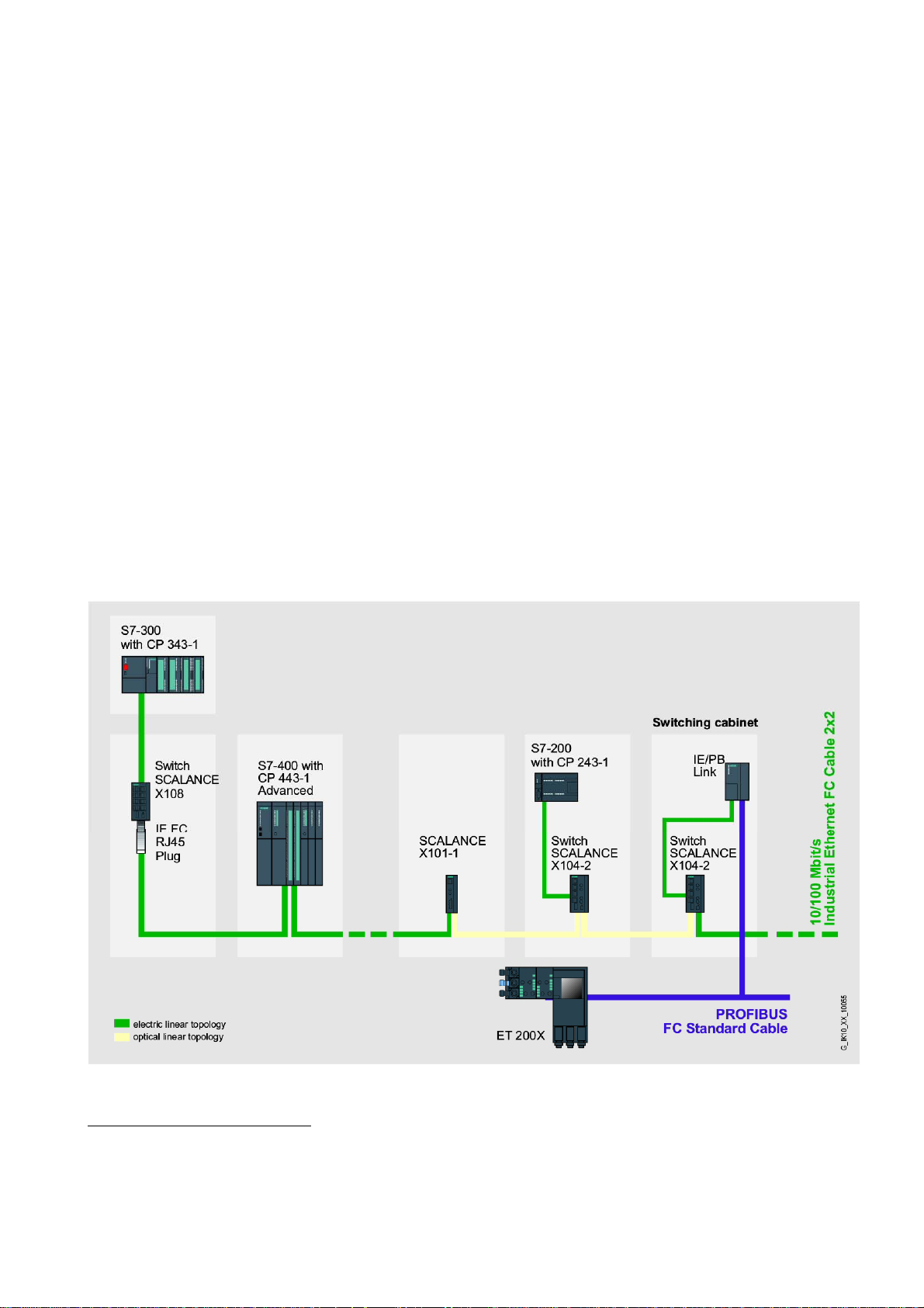
Bus Topology
2
in a ring network. Please compare in chapter 4 Product
3
Figure 3-1 Electrical/optical bus topology with SCALANCE X101-1
2
Only SCALANCE X101-1 or SCALANCE X101-1LD or SCALANCE X101-1POF
Industrial Ethernet Media Converters SCALANCE X-100 Series
Commissioning Manual, 07/2008, A2B00051521A
3-1
Network Topologies
3.1 Network Topologies
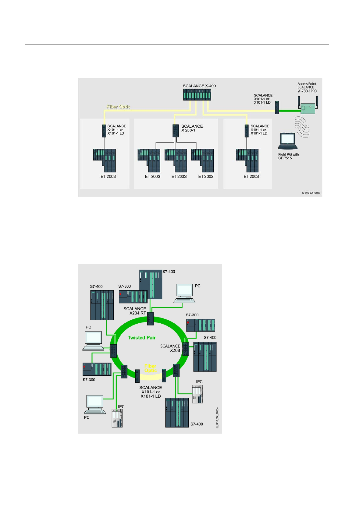
Star Topology
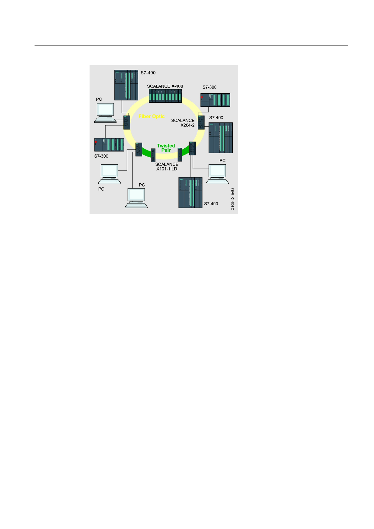
Figure 3-2 Optical Ring, Example with SCALANCE X-400 as Redundancy Manager, X204-2 and a
extension for Optical Lines with SCALANCE X101-1LD Media converter
Ring Topology
See in chapter 4 Product Characteristics, subsection Cascade, of the concerning media
converter.
Figure 3-3 Electrical Ring, Example with SCALANCE X204IRT as Redundancy Manager, X208 and
conversion to a Optical Line with SCALANCE X101-1 or X101-1LD Media converter
Industrial Ethernet Media Converters SCALANCE X-100 Series
3-2 Commissioning Manual, 07/2008, A2B00051521A
Network Topologies
3.1 Network Topologies
Figure 3-4 Optical Ring, Example with SCALANCE X-400 as Redundancy Manager, X204-2 and a
extension for Optical Lines with SCALANCE X101-1LD Media converter
Industrial Ethernet Media Converters SCALANCE X-100 Series
Commissioning Manual, 07/2008, A2B00051521A
3-3
Network Topologies
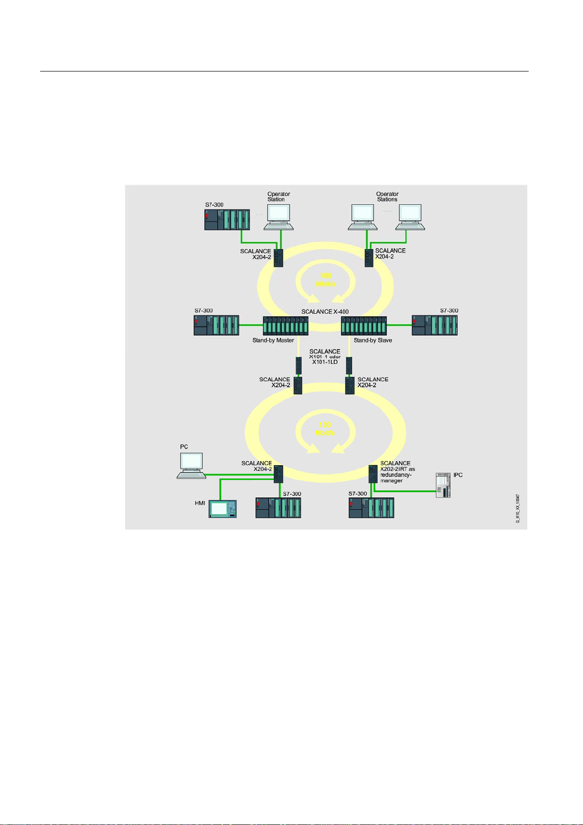
3.2 Coupling of Network Segments
3.2 Coupling of Network Segments
The coupling of two ring network topologies using two SCALANCE X101-1 media converters
shown here as an example is only possible indirectly via nodes with redundancy capability
(e.g. SCALANCE X-400). This applies to all media converters of the SCALANCE X-100
series.
Figure 3-5 Stand-By Coupling of two Redundant Rings via Master / Slave Concept of SCALANCE
X-400. Coupling is realized with SCALANCE X101-1 or X101-1LD Media converter
Industrial Ethernet Media Converters SCALANCE X-100 Series
3-4 Commissioning Manual, 07/2008, A2B00051521A

Product Characteristics
4
4.1 Overview
Table 4-1 Overview of the product characteristics
Characteristics Device type
X101-1 X101-1FL X101-1LD X101-1POF
SIMATIC environment
Diagnostics LED
24V DC + + + +
Compact housing 40mm
(securing collar, etc.)
2x 24 V DC + + + +
Signaling contact + on-site operation
Diagnostics: Web, SNMP,
PROFINET
C-PLUG
Ring redundancy with RM
Ring redundancy passive
Standby redundancy
IRT capability
Fast learning
Passive listening
Log table
SNTP + SICLOCK - - - -
Cut through
+ + + +
+ + + +
+ + + +
+ + + +
- - - -
- - - -
- - - -
+ + + +
- - - -
- - - -
- - - -
- - - -
- - - -
+ + + +
Table 4-2 Overview of the possible attachments
Cable type/transceiver wavelength Device type, interface
X101-1 X101-1FL X101-1LD X101-1POF
TP(RJ-45)
Fiber multimode (BFOC) / 1300nm
Fiber multimode (BFOC) / 820nm
Fiber long distance monomode
(BFOC) /1310nm
Plastic optical fiber (SC-RJ) / 650nm
Industrial Ethernet Media Converters SCALANCE X-100 Series
Commissioning Manual, 07/2008, A2B00051521A
1 1 1 1
1
1
1
1
4-1

Product Characteristics
4.2 SCALANCE X101-1
4.2 SCALANCE X101-1
4.2.1 SCALANCE X101-1 Components Supplied
What ships with the media converter?
• SCALANCE X101-1 device
• 2-pin plug-in terminal block
• 4-pin plug-in terminal block
• Product information
• CD
– Commissioning manual (this document)
– PST tool (only for devices of the SCALANCE X-200 product line)
– GSD file (only for devices of the SCALANCE X-200 product line)
– SNMP OPC profile (only for devices of the SCALANCE X-200 product line)
4.2.2 SCALANCE X101-1 Unpacking and Checking
Unpacking, Checking
1. Make sure that the package is complete.
2. Check all parts for transport damage.
Warning
Do not use any parts that show evidence of damage!
Warning
If the SCALANCE X101-1 device is operated in ambient temperatures between 55°C60°C, the temperature of the device housing may be higher than 70°C.
The subject unit must be located in a Restricted Access Location where access can only
be gained by SERVICE PERSONNEL or by USERS who have been instructed about the
reasons for the restrictions applied to the location and about any precautions that shall be
taken when operated in an ambient temperature of 55°C-60°C.
Industrial Ethernet Media Converters SCALANCE X-100 Series
4-2 Commissioning Manual, 07/2008, A2B00051521A
Product Characteristics
4.2 SCALANCE X101-1
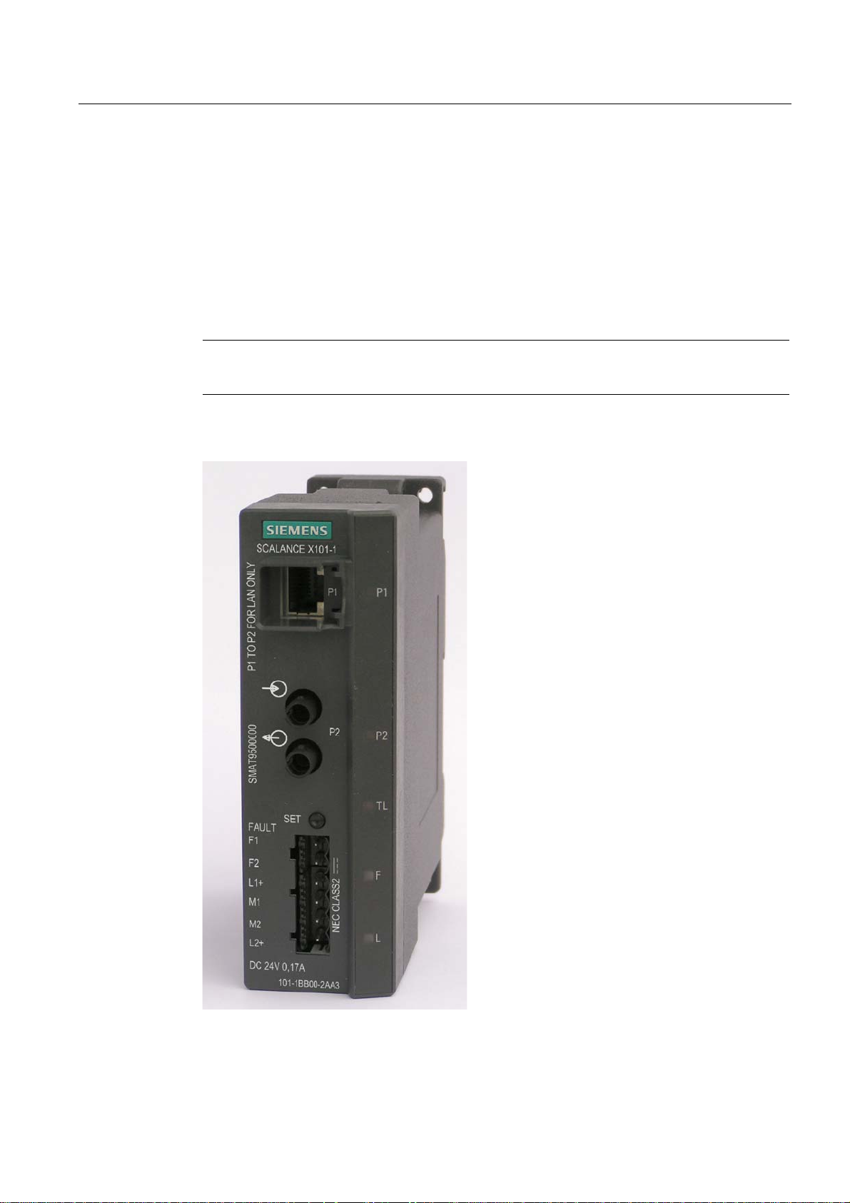
4.2.3 SCALANCE X101-1 Product Characteristics
Possible Attachments
The SCALANCE X101-1 media converter features an RJ-45 jack and a BFOC port for the
connection of DTEs or other network segments.
Note
The BFOC socket (Bayonet Fiber Optic Connector) corresponds to the ST socket
Figure 4-1 SCALANCE X101-1
Industrial Ethernet Media Converters SCALANCE X-100 Series
Commissioning Manual, 07/2008, A2B00051521A
4-3
Product Characteristics
4.2 SCALANCE X101-1
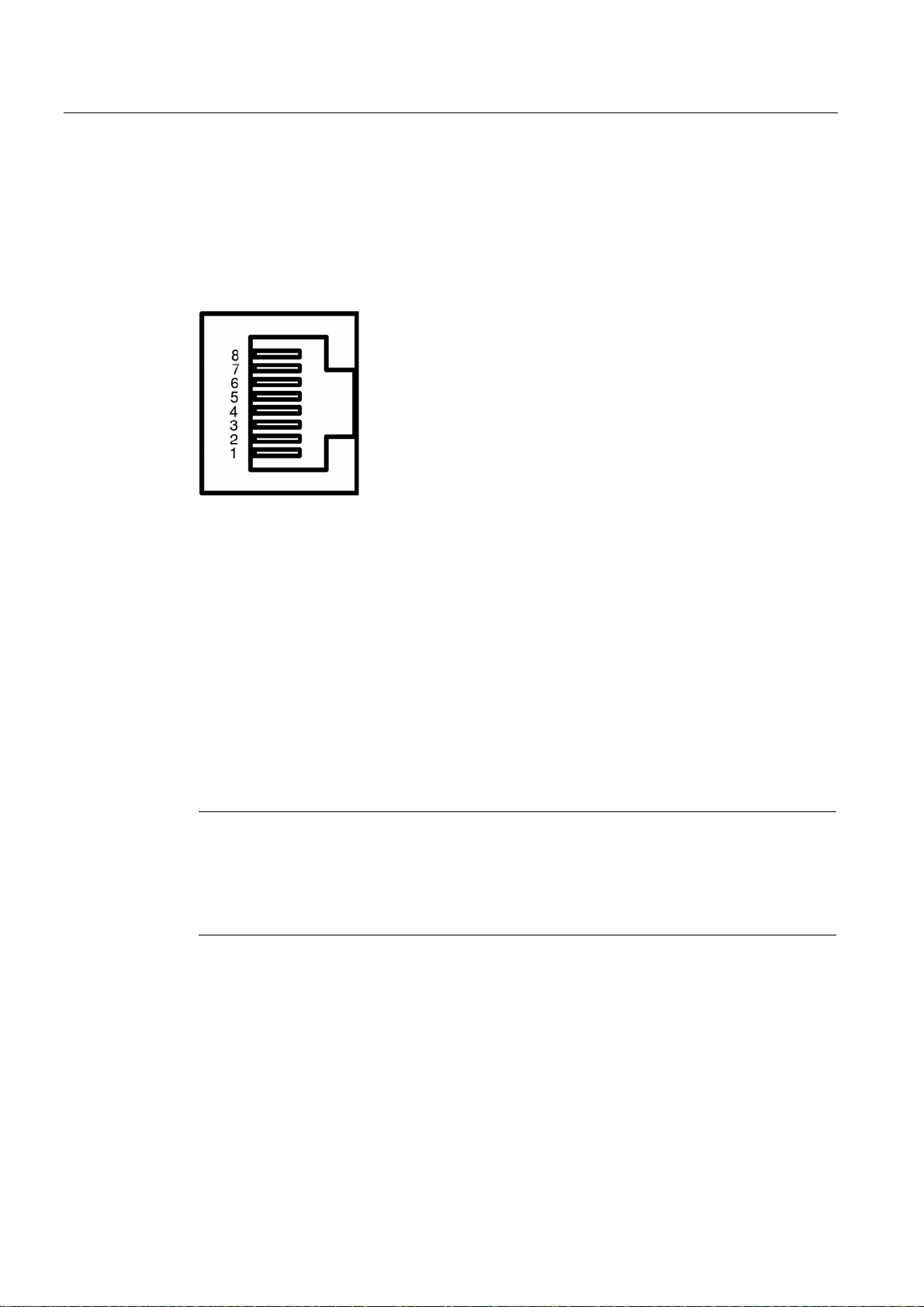
4.2.4 SCALANCE X101-1 TP Port
Connector Pinout
RJ-45 jack
Figure 4-2 RJ-45 connector pinout
Pin number Pinout
Pin 8 NC
Pin 7 NC
Pin 6 TDPin 5 NC
Pin 4 NC
Pin 3 TD+
Pin 2 RDPin 1 RD+
On SCALANCE X101-1, the twisted pair port is implemented as RJ-45 jack with MDI-X
assignment (Medium Dependent Interface–Autocrossover) of a network component.
Notice
TP cords or TP-XP cords with a maximum length of 10 m can be connected to the RJ-45 TP
port.
Depending on the cable type, a total cable length of up to 100 m is permitted between two
devices with the IE FC cables and IE FC RJ-45 plug 180.
Autonegotiation
Autonegotiation means the automatic detection of the functionality of the port at the opposite
end. Using autonegotiation, repeaters or DTEs can detect the functionality available at the
port of a partner device allowing automatic configuration of different types of device. With
autonegotiation, two components connected to a link segment can exchange parameters
and set themselves to match the supported communication functionality.
Industrial Ethernet Media Converters SCALANCE X-100 Series
4-4 Commissioning Manual, 07/2008, A2B00051521A

Product Characteristics
4.2 SCALANCE X101-1
Note
Devices not supporting autonegotiation must be set to 100 Mbps / half duplex.
MDI /MDIX Autocrossover Function
The advantage of the MDI /MDIX autocrossover function is that straight-through cables can
be used throughout and crossover Ethernet cables are unnecessary. This prevents
malfunctions resulting from mismatching send and receive wires. This makes installation
much easier for the user.
All media converters of the SCALANCE X-100 series support the MDI / MDIX autocrossover
function.
4.2.5 SCALANCE X101-1 FO Port
Transmission Speed
The transmission rate of the optical Fast Ethernet port is 100 Mbps.
Transmission Mode
The transmission mode for 100Base-FX is specified in the IEEE 802.3 standard.
Since the full duplex mode and the transmission rate cannot be modified for optical
transmission, autonegotiation cannot be selected.
Transmission Medium
The data are transferred over multimode fiber-optic cable (FOC). The transceiver wavelength
is 1300 nm.
Multimode fiber-optic cables are used with a core diameter of 50 or 62.5 µm, the light source
is an LED.
The outer diameter of the FOC is 125 µm.
Range
The maximum transmission range (segment length) is 3 km if the signal attenuation of the
FOC is ≤ 1 dB/km at 1300 nm.
Connectors
The cables are connected to BFOC sockets.
Industrial Ethernet Media Converters SCALANCE X-100 Series
Commissioning Manual, 07/2008, A2B00051521A
4-5
Product Characteristics
4.2 SCALANCE X101-1
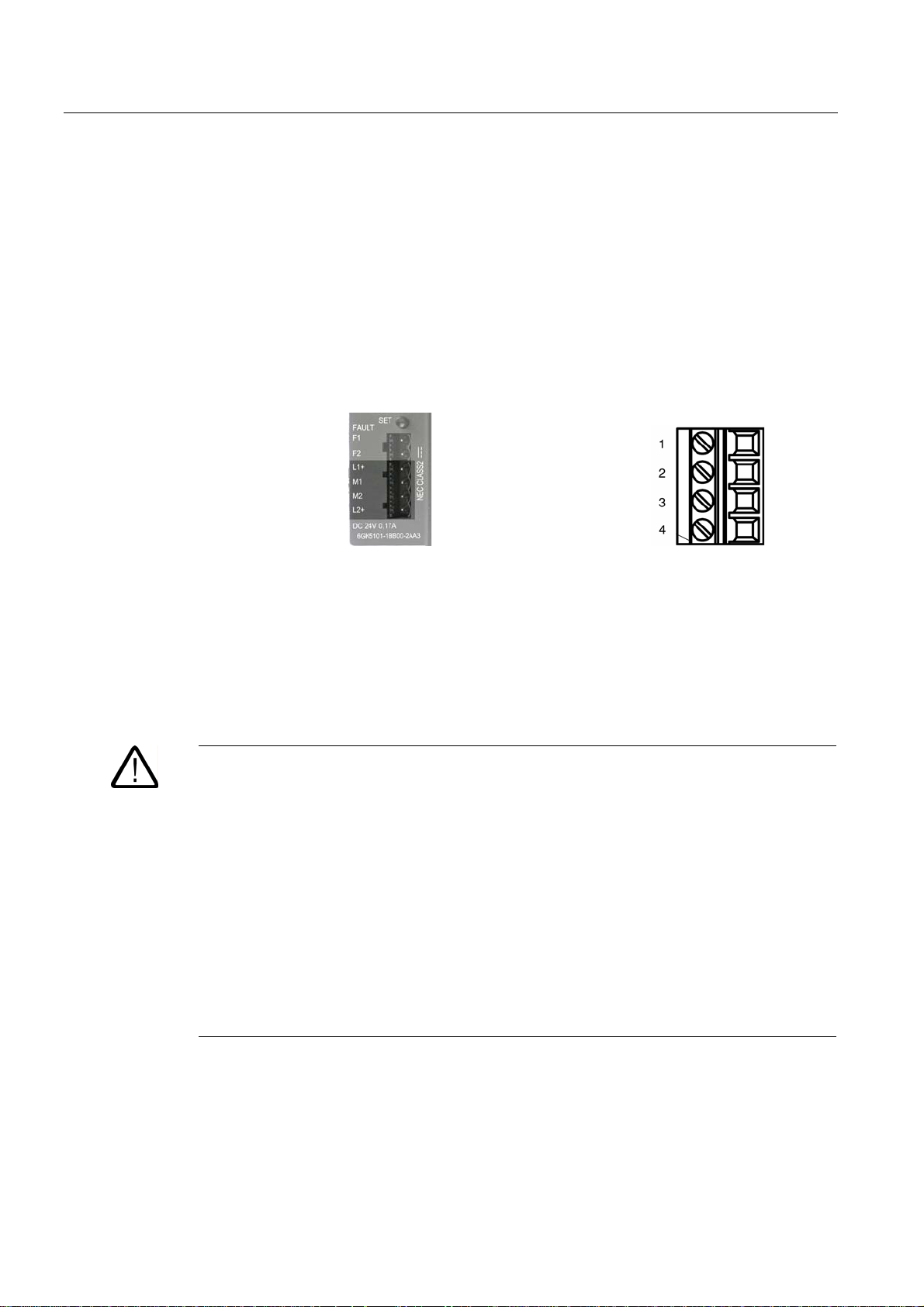
4.2.6 SCALANCE X101-1 Power Supply and Signaling Contact
Power Supply
The power supply is connected using a 4-pin plug-in terminal block. The power supply can
be connected redundantly. Both inputs are isolated. There is no distribution of load. When
using a redundant power supply, the power supply unit with the higher output voltage
supplies SCALANCE X101-1 alone. The power supply is connected over a high resistance
with the enclosure to allow an ungrounded setup.
Figure 4-3 Power supply SCALANCE X101-1 Figure 4-4 Connector pinout
Pin number Pinout
Pin 1 L1+ (+18 - 32V DC)
Pin 2 M1 (ground)
Pin 1 M2 (ground)
Pin 2 L2+ (+18 - 32V DC)
Warning
The SCALANCE X101-1 device is designed for operation with safety extra-low voltage. This
means that only safety extra-low voltages (SELV) complying with IEC950/EN60950/
VDE0805 can be connected to the power supply terminals.
The power supply unit to supply SCALANCE X101-1 must comply with NEC Class 2 (voltage
range 18-32 V, current requirement 200 mA).
If the device is connected to a redundant power supply (two separate power supplies), both
must meet these requirements.
The signaling contact can be subjected to a maximum load of 100 mA (safety extra-low
voltage (SELV), DC 24 V).
Never connect SCALANCE X101-1 to AC voltage.
Never operate SCALANCE X101-1 with DC voltage higher than 32 V DC.
Industrial Ethernet Media Converters SCALANCE X-100 Series
4-6 Commissioning Manual, 07/2008, A2B00051521A

Product Characteristics
4.2 SCALANCE X101-1
Signaling Contact
The signaling contact is connected to a 2-pin plug-in terminal block. The signaling contact
(optical relay contact) is a floating switch with which error/fault states are signaled by contact
separation.
Figure 4-5 Signaling contact SCALANCE X101-1 Figure 4-6 Connector pinout
The following errors/faults can be signaled by the signaling contact:
• The failure of a link at one of the two monitored ports.
• The failure of one of the two redundant power supply units.
Connecting or disconnecting a communication node at an unmonitored port does not cause
an error message.
The signaling contact remains activated until the error/fault is eliminated or until the current
status is applied as new desired status by the button.
When turning off the device, the signaling contact is always activated (open).
4.2.7 SCALANCE X101-1 Button
What is the function of the button?
Using the button, you can display and modify the set fault mask and set the transparent link
mode (see chapter
4.2.8).
Pin number Pinout
Pin 1 F1
Pin 2 F2
After continuously pressing the button, the currently valid fault mask is displayed for
approximately 3 seconds. The LED of the monitored port flashes at a frequency of 5 Hz.
Keep the button pressed to modify the fault mask. After another 3 seconds,
of the ports and the indicator of the power supply LEDs are displayed at a flashing
status
frequency of 2.5 Hz. Keep the button pressed. After another 3 seconds,
as new fault mask and saved. The now monitored ports are indicated by the permanently lit
LEDs until the button is released. As long as the LEDs are still flashing, the saving can be
canceled by releasing the button.
Industrial Ethernet Media Converters SCALANCE X-100 Series
Commissioning Manual, 07/2008, A2B00051521A
the current link
this status is applied
4-7

Product Characteristics
4.2 SCALANCE X101-1
If an empty fault mask (no port is monitored) is set or is to be set, the 2 port LEDs flash
alternatingly.
Simultaneously with the fault mask, the monitoring of the connected power supply is set. The
existence of
connected during saving the fault mask.
The failure of the link on a monitored port or of one of the monitored power supplies is
indicated by the illuminated red error LED. The signaling contact is opened simultaneously.
the two power supply units is only monitored if both power supplies are
Note
The factory default is no port monitoring but monitoring of the power supply L1+/M1. If
necessary, error LED and signaling contact have to be cleared by pressing the button for an
appropriate period or the feeding point has to be changed when connecting
supply to L2+/M2.
The setting remains after turning off/on.
4.2.8 Cascade Connection of two Media Converters
If you cascade two media converters, i.e. connect the converters via the FO port, it is
mandatory to previously activate this operating mode using the button. Keep the button
pressed for 1-2 seconds. After releasing, the acceptance of the operating mode is indicated
by the illuminated “TL” (transparent link) LED. Again press the button for 1-2 seconds to exit
this operating mode. The “TL” LED is extinguished.
Important notes:
• Max. two media converters can be cascaded
• mixed cascading with SCALANCE X-100 Media converter and OMC-Media
converter is not possible
only one power
• The cascade connection is only permitted via the connection of the FO ports!
• It is mandatory that a cascade connection is set at both (!) media converters using
the button (“ TL” LED must be illuminated). If this is not done, malfunctions can
occur.
• The setting remains after turning on/off.
• The factory setting is “ stand-alone mode” , i.e. no cascade is set
Industrial Ethernet Media Converters SCALANCE X-100 Series
4-8 Commissioning Manual, 07/2008, A2B00051521A

Product Characteristics
4.2 SCALANCE X101-1
4.2.9 SCALANCE X101-1 Displays
Fault indicator (red LED) )
Status Meaning
Lit red SCALANCE X101-1 detects an error. Simultaneously the
Not lit No error was detected by SCALANCE X101-1.
Power indicator (green LED)
The status of the power supply is indicated by a green LED:
Status Meaning
Lit green Power supply L1 or L2 are connected.
Not lit Power supply L1 and L2 is not connected or L1 and L2 <14 V
signaling contact opens.
The following errors are detected:
1. Link down event at a monitored port.
2. Failure of the supply voltage or supply voltage less than
14 V of one of the two redundant power supplies. See also
note in chapter 4.2.7
Comment: If the green LED is not lit, no other signal LED is lit.
Port status indicator (green/yellow LEDs) )
The status of the ports is indicated by 2 LEDs:
Status Meaning
Port 1: LED lit green link exists, no data reception at TP port
Port 2: LED lit green
Port 1: LED lit yellow link exists, data received at TP port
Port 2: LED lit yellow
Port 1 and 2: LEDs flash yellow
Note
The link state of port P1 and port P2 (LED lit green) in stand-alone-mode is only indicated if
both ports have link at the same time.
In transparent link mode the link state is also recognized and indicated by the optical
port(P2) without a link at the port P1 (see chapter 4.2.8).
link exists, no data reception at FOC
link exists, data received at FOC port
Setting or display of the fault mask
Industrial Ethernet Media Converters SCALANCE X-100 Series
Commissioning Manual, 07/2008, A2B00051521A
4-9

Product Characteristics
4.2 SCALANCE X101-1
Transparent link display (green LED)
“TL” (transparent link) LED:
Status Meaning
Lit green Transparent link parameterized.
Not lit Stand-alone mode. DTEs are connected to both ports of the
media converter (no cascading)
See chapter 4.2.8 "Important notes"!
Industrial Ethernet Media Converters SCALANCE X-100 Series
4-10 Commissioning Manual, 07/2008, A2B00051521A

Product Characteristics
4.2 SCALANCE X101-1
4.2.10 SCALANCE X101-1 Technical Specifications
Technical Specifications of SCALANCE X101-1
Ports
Attachment of DTEs or network components over
twisted pair
Connection of further network components over
FOC
Connector for power supply 1x4-pin plug-in terminal block
Connector for signaling contact 1x2-pin plug-in terminal block
Electrical Data
Power supply 2 x DC 24 V
Power loss at DC 24 V (typ.) 3 W
Current consumption at rated voltage (typ.) 120 mA
Minimum rated current of the power supply 170 mA
Overvoltage protection at input PTC resettable fuse (0.5 A / 60 V)
Permitted Cable Lengths
Network span parameter/TP cable length
0 – 100 m
0 – 85 m
Network span parameter/FO cable length
0 - 3000 m
1xRJ-45 socket with MDI-X pinning 100 Mbps
full duplex
2 BFOC sockets
(100 Mbps, full duplex to 100 BaseFX)
(DC 18 - 32 V)
safety extra-low voltage (SELV)
IE FC TP standard cable with IE FC RJ-45
plug 180
or
IE FC outlet RJ-45 with IE FC TP standard cable
(0 - 90 m) + 10 m TP cord
IE FC TP marine/trailing/flexible with IE FC RJ-45
plug 180
or
IE FC TP marine/trailing/flexible (0 – 75 m) + 10
m TP cord over IE FC outlet RJ-45
Glass FOC
62.5/125 µm or 50/125 µm glass fiber;
≤ 1 dB/km at 1300 nm;
1200 MHz x km at 1300 nm;
6 dB max. permitted FO cable attenuation with 3
dB link power margin
Bending radius once without tensile force:
100 mm
bending radius repeatedly with tensile force:
150 mm
Industrial Ethernet Media Converters SCALANCE X-100 Series
Commissioning Manual, 07/2008, A2B00051521A
4-11

Product Characteristics
4.2 SCALANCE X101-1
Permitted Environmental Conditions / EMC
Operating temperature -10°C to +60°C
Storage/transport temperature -40°C to +80°C
Relative humidity in operation ‹ 95% (no condensation)
Operating altitude 2000 m at max 56 °C ambient temperature
3000 m at max. 50 °C ambient temperature
RF interference level EN 61000-6-3
Noise immunity EN 61000-6-2
Degree of protection IP30
Approvals
c-UL-us
c-Ul-us for hazardous locations
3
FM
3
C-Tick
CE
ATEX Zone 2
3
MTBF
MTBF
Construction
Dimensions (W x H x D) in mm
Weight in g
Installation options DIN rail
UL 60950
CSA C22.2 No. 60950
UL 1604, UL 2279Pt.15
CL. 1, Div. 2 GP. A.B.C.D T..
CL. 1, Zone 2, GP. IIC, T..
CL. 1, Zone2, AEx nC IIC T..
FM 3611
CL. 1, Div. 2 GP. A.B.C.D T..
CL. 1, Zone 2, GP. IIC, T..
Ta: ..
AS/NZS 2064 (Class A).
EN 61000-6-2, EN 61000-6-4
EN60079-15:2005
EN60079-0:2006
II 3 G Ex nA II T..
KEMA 08 ATEX 0003 X
134 years
40 x 125 x 124
550
S7-300 DIN rail
Wall mounting
3
Temperature code "T.." and maximum ambient temperature "Ta: .." as indicated on marking plate
Industrial Ethernet Media Converters SCALANCE X-100 Series
4-12 Commissioning Manual, 07/2008, A2B00051521A
 Loading...