

Siemens SCALANCE X101-1AUI Commissioning Manual

SIMATIC NET
SIMATIC NET
Industrial Ethernet
SCALANCE X101-1AUI
Commissioning Manual
Introduction
Network Topologies
Product Characteristics
Installation and Maintenance
Notes on the CE Mark
References
Dimension Drawings
1
2
3
4
5
6
7
06/2006
A2B00051526A, Product Version 03
Safety Guidelines
This manual contains notices which you should observe to ensure your own personal safety as well as to avoid
property damage. The notices referring to your personal safety are highlighted in the manual by a safety alert
symbol, notices referring to property damage only have no safety alert symbol. Depending on the danger level,
the notices are displayed in descending order as follows.
Danger
indicates that death or severe personal injury will result if proper precautions are not taken.
Warning
indicates that death or severe personal injury may result if proper precautions are not taken.
Caution
with safety alert symbol indicates that minor personal injury can result if proper precautions are not taken.
Caution
without safety alert symbol indicates that property damage can result if proper precautions are not taken.
Notice
used without safety alert symbol indicates a potential situation which, if not avoided, may result in an undesirable
result or state.
When several danger levels apply, the notices of the highest level (lower number) are always displayed. If a
notice refers to personal damages with the safety alert symbol, then another notice may be added warning of
property damage.
Qualified Personnel
The device/system may only be set up and operated in conjunction with this documentation. Only qualified
personnel should be allowed to install and work on the equipment. Only qualified personnel should be allowed to
install and work on the equipment. Qualified persons are defined as persons who are authorized to commission,
to earth, and to tag circuits, equipment and systems in accordance with established safety practices and
standards.
Intended Use
Please note the following:
Warning
This device and its components may only be used for the applications described in the catalog or technical
description, and only in connection with devices or components from other manufacturers approved or
recommended by Siemens. This product can only function correctly and safely if it is transported, stored, set up
and installed correctly, and operated and maintained as recommended.
Trademarks
All designations marked with ® are registered trademarks of Siemens AG. Other designations in this
documentation might be trademarks which, if used by third parties for their purposes, might infringe upon the
rights of the proprietors.
Copyright Siemens AG 2006. All rights reserved.
Reproduction, transmission or use of this document or its contents is not permitted without
express written authority. Offenders will be liable for damages. All rights, including rights
created by patent grant or registration of a utility model or design, are reserved.
Siemens AG
Automation and Drives Group
P.O. Box 4848, D-90327 Nuremberg (Germany)
Siemens Aktiengesellschaft A2B00051526A, Product Version 03
Disclaimer of Liability
We have checked the contents of this manual for agreement with the hardware and
software described. Since deviations cannot be precluded entirely, we cannot guarantee
full agreement. However, the data in the manual are reviewed regularly, and any
necessary corrections will be included in subsequent editions.
Siemens AG 2006
Technical data subject to change

Table of Contents
1 Introduction............................................................................................................................................. 1-1
1.1 Introduction ................................................................................................................................ 1-1
2 Network Topologies................................................................................................................................ 2-1
2.1 Network Topologies ................................................................................................................... 2-1
2.2 Coupling of Network Segments ................................................................................................. 2-1
3 Product Characteristics........................................................................................................................... 3-1
3.1 Overview .................................................................................................................................... 3-1
3.2 SCALANCE X101-1AUI Components Supplied ....................................................................... 3-2
3.3 SCALANCE X101-1AUI Unpacking and Checking................................................................... 3-2
3.4 SCALANCE X101-1AUI Product Characteristics...................................................................... 3-3
3.5 SCALANCE X101-1AUI TP-RJ-45 Interface ............................................................................ 3-4
3.6 SCALANCE X101-1AUI AUI Interface...................................................................................... 3-5
3.7 SCALANCE X101-1AUI Power Supply and Signaling Contact ................................................ 3-7
3.8 SCALANCE X101-1AUI Button................................................................................................. 3-8
3.9 SCALANCE X101-1AUI LEDs ................................................................................................ 3-10
3.10 SCALANCE X101-1AUI Technical Specifications .................................................................. 3-11
4 Installation and Maintenance .................................................................................................................. 4-1
4.1 Installation.................................................................................................................................. 4-1
4.1.1 Installation on a DIN Rail ........................................................................................................... 4-2
4.1.2 Installation on a DIN Rail ........................................................................................................... 4-4
4.1.3 Wall Mounting ............................................................................................................................ 4-5
4.2 Grounding .................................................................................................................................. 4-5
4.3 Assembling the IE FC Standard Cable ...................................................................................... 4-6
4.4 Assembling the AUI Cable......................................................................................................... 4-9
4.5 Maintenance............................................................................................................................. 4-10
5 Notes on the CE Mark ............................................................................................................................ 5-1
5.1 Notes on the CE Mark................................................................................................................ 5-1
6 References ............................................................................................................................................. 6-1
6.1 References................................................................................................................................. 6-1
7 Dimension Drawings...............................................................................................................................7-1
7.1 Dimension Drawing.................................................................................................................... 7-1
Industrial Ethernet Media Converters SCALANCE X-100 Series
Commissioning Manual, 06/2006, A2B00051526A, Product Version 03
iii

Table of Contents
Tables
Table 3-1 Overview of the product characteristics ..................................................................................... 3-1
Table 3-2 Overview of the possible attachments ....................................................................................... 3-1
Figures
Figure 2-1 Connection of a SCALANCE X108 to an AUI segment (e.g. 10Base5 ) via
SCALANCE X101-1AUI
Figure 3-1 SCALANCE X101-1AUI ............................................................................................................. 3-3
Figure 3-2 RJ-45 connector pinout.............................................................................................................. 3-4
Figure 3-3 15-pin SUB-D connector pinout ................................................................................................. 3-6
Figure 3-4 SCALANCE X101-1AUI power supply....................................................................................... 3-7
Figure 3-5 Connector pinout........................................................................................................................ 3-7
Figure 3-6 SCALANCE X101-1AUI signaling contact ................................................................................. 3-8
Figure 3-7 Connector pinout........................................................................................................................ 3-8
............................................................................................................. 2-1
Figure 4-1 Installation on a DIN rail (35 mm) .............................................................................................. 4-2
Figure 4-2 Removing from a DIN rail (35 mm) ............................................................................................ 4-3
Figure 4-3 Installation on a SIMATIC S7-300 DIN rail................................................................................. 4-4
Figure 4-4 IE FC RJ-45 plug 180................................................................................................................. 4-6
Figure 4-5 Inserting the IE FC RJ-45 plug 180............................................................................................ 4-7
Figure 4-6 Unlatching the RJ-45 plug.......................................................................................................... 4-8
Figure 4-7 Locking in open position............................................................................................................. 4-9
Figure 4-8 Locking or unlocking the SUB-D connector ............................................................................... 4-9
Figure 7-1 Dimension drawing..................................................................................................................... 7-1
Figure 7-2 SCALANCE X101-1AUI side view ............................................................................................. 7-2
Industrial Ethernet Media Converters SCALANCE X-100 Series
iv Commissioning Manual, 06/2006, A2B00051526A, Product Version 03

Introduction
1.1 Introduction
This chapter provides you with an overview of the functions of the unmanaged Industrial
Ethernet media converter SCALANCE X101-1AUI.
Purpose of the Commissioning Manual
This commissioning manual supports you when commissioning networks with the
SCALANCE X101-1AUI media converter.
Validity of this Commissioning Manual
This commissioning manual is valid for the following device:
SIMATIC NET SCALANCE X101-1AUI 6GK5101-1BX00-2AA3
Further Documentation
The “SIMATIC NET Industrial Ethernet Twisted Pair and Fiber Optic Networks” manual
contains additional information on other SIMATIC NET products that you can operate along
with SCALANCE X101-1AUI in an Industrial Ethernet network.
1
Finding information
To help you find the information you require more quickly, the manual includes not only the
table of contents but also the following sections in the Appendix:
Glossary
•
•
Index
Audience
This commissioning manual is intended for persons involved in the commissioning of
networks with SCALANCE X101-1AUI.
Industrial Ethernet Media Converters SCALANCE X-100 Series
Commissioning Manual, 06/2006, A2B00051526A, Product Version 03
1-1

Introduction
1.1 Introduction
Standards and Approvals
SCALANCE X101-1AUI meets the requirements for the CE mark. For detailed information
please refer to the chapter "Notes on the CE Mark" of this commissioning manual.
The SCALANCE X101-1AUI media converter meets the requirements for the UL , C-Tick ,
FM and ATEX marks . For detailed information please refer to the technical specifications in
the “Approvals” heading of this commissioning manual.
What Is Possible?
The SCALANCE X-101-1AUI device enables the cost-effective installation of Industrial
Ethernet bus and star structures with a media transition.
Note
It is not possible to use a SCALANCE X101-1AUI media converter in a redundant ring since
it does not support the redundancy function.
Note
The requirements of EN61000-4-5, surge test on power supply lines, are met only when a
Blitzductor VT AD 24V type no. 918 402 is used
Manufacturer:
DEHN+SÖHNE GmbH+Co.KG Hans Dehn Str.1 Postfach 1640 D-92306 Neumarkt,
Germany
Warning
When used under hazardous conditions (zone 2), the SCALANCE X101-1AUI media
converter must be installed in an enclosure.
In the scope of ATEX100a (EN 60079-15), this enclosure must at least comply with IP54
according to EN 60529.
WARNING – EXPLOSION HAZARD: THE DEVICE MUST ONLY BE CONNECTED TO OR
DISCONNECTED FROM THE POWER SUPPLY IF AN EXPLOSION HAZARD CAN BE
DEFINITELY EXCLUDED.
Industrial Ethernet Media Converters SCALANCE X-100 Series
1-2 Commissioning Manual, 06/2006, A2B00051526A, Product Version 03
Note
The specified approvals apply only when the corresponding mark is printed on the product.
Network Topologies
2.1 Network Topologies
Which network topologies can be implemented?
Using the SCALANCE X101-1AUI Industrial Ethernet media converter, a transition between
TP and AUI technology can be implemented in bus or star topologies.
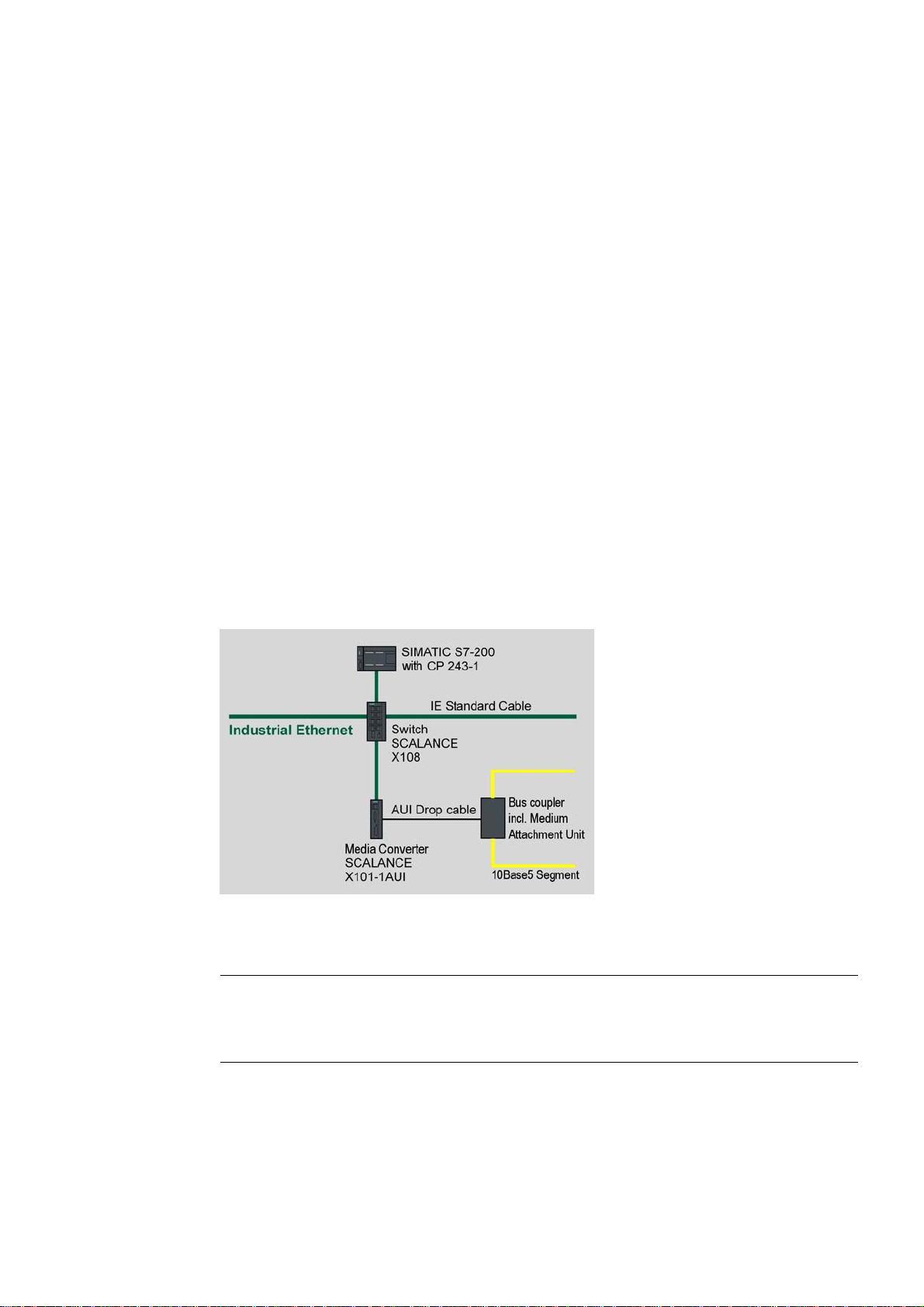
2.2 Coupling of Network Segments
The coupling shown here as an example illustrates the connection of an Industrial Ethernet
switch to an existing 10Base5 segment.
2
Figure 2-1 Connection of a SCALANCE X108 to a 10Base5 segment via SCALANCE X101-1AUI
Industrial Ethernet Media Converters SCALANCE X-100 Series
Commissioning Manual, 06/2006, A2B00051526A, Product Version 03
Note
SCALANCE X101-1AUI is a repeater. This has to be considered when connecting and
designing the network topology (repeater rule).
2-1


Product Characteristics
3.1 Overview
Table 3-1 Overview of the product characteristics
Characteristics Device type
X101-1AUI
SIMATIC environment
Diagnostics LED
24V DC +
Compact housing 40mm
(securing collar, etc.)
2x 24 V DC +
Medium Attachment Unit (MAU) –
supply with 12 V
Signaling contact + on-site operation
Diagnostics: Web, SNMP,
PROFINET
C-PLUG
Ring redundancy with RM
Standby redundancy
IRT capability
Fast learning
+
+
+
+
+
-
-
-
-
-
-
3
Table 3-2 Overview of the possible attachments
Characteristics Device type
X101-1AUI
TP(RJ45) 1
Attachment Unit Interface (AUI)
for connecting a
Medium Attachment Unit (MAU)
1
Industrial Ethernet Media Converters SCALANCE X-100 Series
Commissioning Manual, 06/2006, A2B00051526A, Product Version 03
3-1
Product Characteristics
3.2 SCALANCE X101-1AUI Components Supplied
3.2 SCALANCE X101-1AUI Components Supplied
What ships with the SCALANCE X101-1AUI?
• SCALANCE X101-1AUI device
• 2-pin plug-in terminal block
• 4-pin plug-in terminal block
• Product information
• CD
– Commissioning manual (this document)
– PST tool (only for devices of the SCALANCE X-200 product line)
– GSD file (only for devices of the SCALANCE X-200 product line)
– SNMP OPC profile (only for devices of the SCALANCE X-200 product line)
3.3 SCALANCE X101-1AUI Unpacking and Checking
Unpacking, Checking
1. Make sure that the package is complete.
2. Check all parts for transport damage.
Warning
Do not use any parts that show evidence of damage!
Warning
If the SCALANCE X101-1AUI device is operated in ambient temperatures between 55°C60°C, the temperature of the device housing may be higher than 70°C.
The subject unit must be located in a Restricted Access Location where access can only
be gained by SERVICE PERSONNEL or by USERS who have been instructed about the
reasons for the restrictions applied to the location and about any precautions that shall be
taken when operated in an ambient temperature of 55°C -60°C.
Industrial Ethernet Media Converters SCALANCE X-100 Series
3-2 Commissioning Manual, 06/2006, A2B00051526A, Product Version 03
3.4 SCALANCE X101-1AUI Product Characteristics
3.4 SCALANCE X101-1AUI Product Characteristics
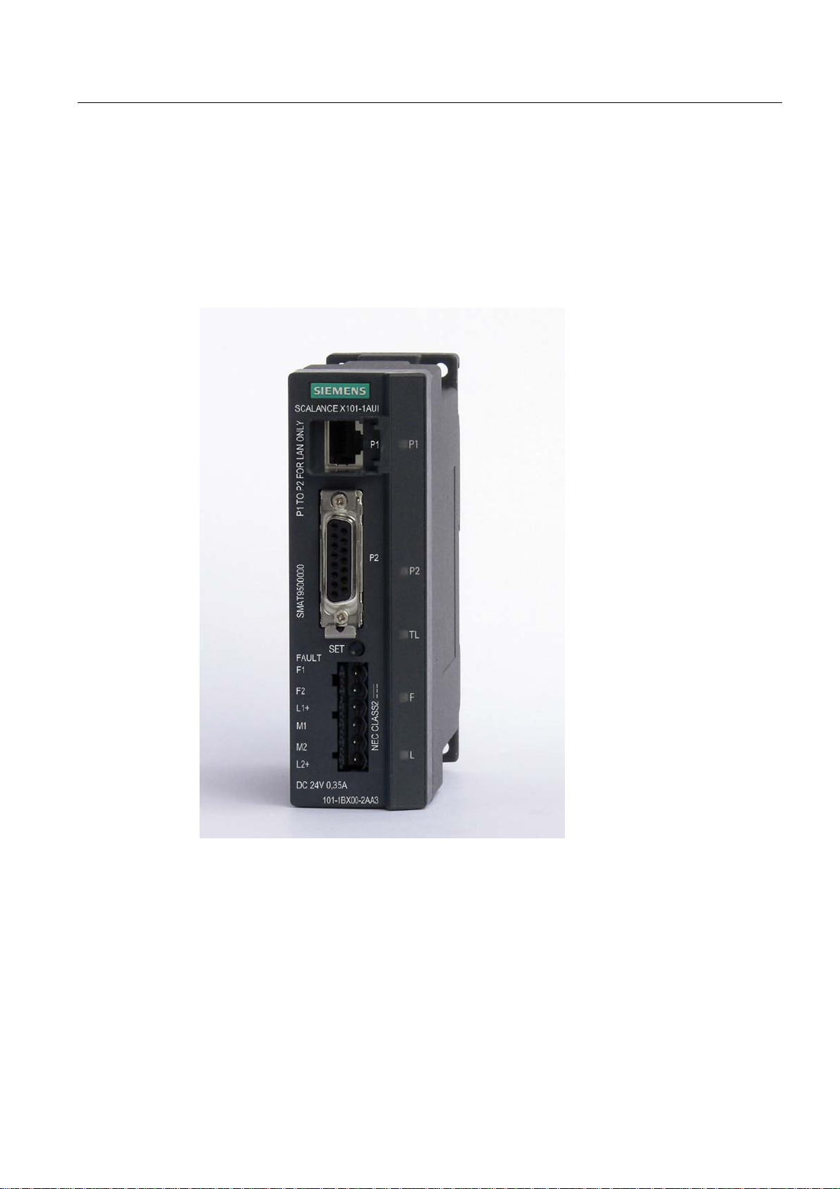
Possible Attachments
SCALANCE X101-1AUI features an RJ-45 jack and a 15-pin SUB D socket for the
connection to AUI transceivers (MAU, Medium Attachment Unit).
Product Characteristics
Figure 3-1 SCALANCE X101-1AUI
Industrial Ethernet Media Converters SCALANCE X-100 Series
Commissioning Manual, 06/2006, A2B00051526A, Product Version 03
3-3
Product Characteristics
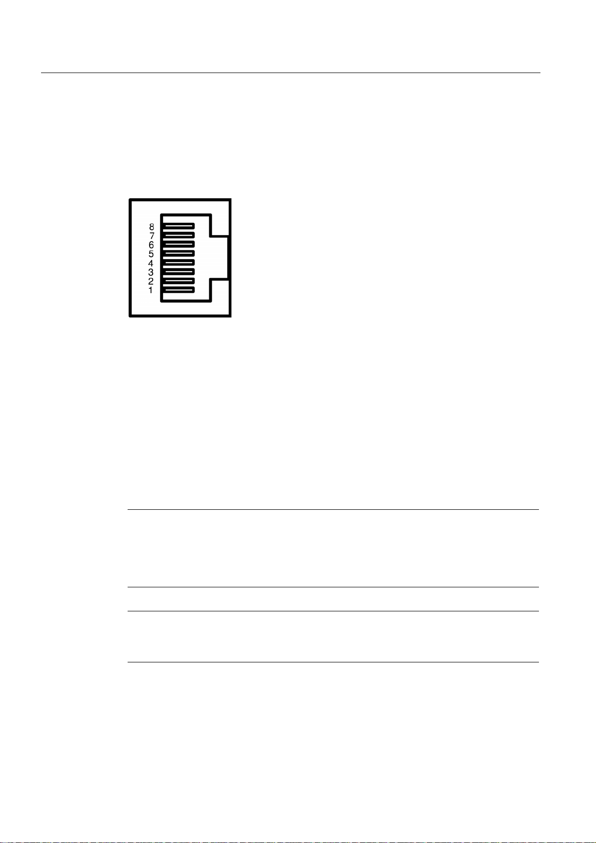
3.5 SCALANCE X101-1AUI TP-RJ-45 Interface
3.5 SCALANCE X101-1AUI TP-RJ-45 Interface
Connector pinout
RJ-45 jack
Figure 3-2 RJ-45 connector pinout
Pin number Pinout
Pin 8 NC
Pin 7 NC
Pin 6 TDPin 5 NC
Pin 4 NC
Pin 3 TD+
Pin 2 RDPin 1 RD+
On SCALANCE X101-1AUI, the twisted pair port is implemented as RJ-45 jack.
Notice
TP cords or TP-XP cords with a maximum length of 10 m can be connected to the RJ-45 TP
port.
Depending on the cable type, a total cable length of up to 100 m is permitted between two
devices with the IE FC cables and IE FC RJ-45 plug 180.
Note
The transmission mode of Scalance X101-1AUI is set to 10 Mbps half duplex.
Devices not supporting autonegotiation must be set to 10 Mbps / half duplex.
Industrial Ethernet Media Converters SCALANCE X-100 Series
3-4 Commissioning Manual, 06/2006, A2B00051526A, Product Version 03

MDI /MDIX Autocrossover Function
The advantage of the MDI /MDIX autocrossover function is that straight-through cables can
be used throughout and crossover Ethernet cables are unnecessary. This prevents
malfunctions resulting from mismatching send and receive wires. This makes installation
much easier for the user.
All devices of the SCALANCE X-101 product line support the MDI / MDIX autocrossover
function.
Product Characteristics
3.6 SCALANCE X101-1AUI AUI Interface
Note
Autopolarity is not supported.
3.6 SCALANCE X101-1AUI AUI Interface
Transmission Rate
The transmission rate is 10 Mbps.
Transmission Mode
The AUI transmission mode is specified in the IEEE 802.3 standard.
Since half duplex mode and the transmission rate of 10Mbps are specified, autonegotiation
cannot be selected on the TP port.
Transmission Medium
AUI cable (drop cable / EFB Ethernet transceiver cable)
Range
The maximum transmission range (segment length) is 50 m.
Medium Attachment Unit – Supply
At 12 V, maximally 500 mA are provided to a Medium Attachment Unit.
Connectors
Interlocking 15-pin SUB-D connectors are used for the connection.
Industrial Ethernet Media Converters SCALANCE X-100 Series
Commissioning Manual, 06/2006, A2B00051526A, Product Version 03
3-5
 Loading...