

Siemens SCALANCE W788-1PRO, SCALANCE W788-1RR, SCALANCE W788-2RR, SCALANCE W788-2PRO Operating Instructions Manual
Page 1

SIMATIC NET
perating Instructions O
SCALANCE W788-1PRO
(Access Point)
SCALANCE W788-2PRO
(Dual Access Point)
Preface, Contents
Basic Information on
Wireless LAN
Communication
Description of the
SCALANCE W78x
1
2
SCALANCE W788-1RR
(Access Point iPCF)
SCALANCE W788-2RR
Dual Access Point iPCF) (
Commissioning
Configuring the IP Address
with the Primary Setup Tool
Configuration Using the
Wizards of
Web Based Management
Configuration Using Web
Based Management and the
Command Line Interface
Technical Specifications
3
4
5
6
7
C79000-G8976-C184-07
Release 10/2006
Approvals, Appendix, Glossary,
Index
Page 2

Classification of Safety-Related Notices
This document contains notices which you should observe to ensure your own
personal safety, as well as to protect the product and connected equipment. These
notices are highlighted in the manual by a warning triangle and are marked as follows
according to the level of danger:
!
Danger
indicates that death or severe personal injury will result if proper precautions are not
taken.
!
Warning
indicates that death or severe personal injury can result if proper precautions are not
taken.
!
Caution
with warning triangle indicates that minor personal injury can result if proper
precautions are not taken.
Caution
without warning triangle indicates that damage to property can result if proper
precautions are not taken.
Notice
indicates that an undesirable result or status can occur if the relevant notice is
ignored.
Note
highlights important information on the product, using the product, or part of the
documentation that is of particular importance and that will be of benefit to the user.
© Copyright Siemens AG, 1998 to 2006 - All rights reserved
The reproduction, transmission or use of this document or its contents is
not permitted without express written authority. Offenders will be liable fo
damages. All rights, including rights created by patent grant or registration
of a utility model or design, are reserved.
Siemens AG
Automation and Drives
Industrial Communication
Postfach 4848, D-90327 Nürnberg
Siemens Aktiengesellschaft Printed in the Federal Republic of Germany
Disclaimer
We have checked the contents of this manual for agreement with the
hardware and software described. Since deviations cannot be preclude
r
entirely, we cannot guarantee full agreement. However, the data in this
manual are reviewed regularly and any necessary corrections included in
subsequent editions. Suggestions for improvement are welcome.
C79000-G8976-C184-07
Technical data subject to change.
d
Page 3

Trademarks
SIMATIC®, SIMATIC NET®, SINEC®, SIMATIC NET Networking for Industry® and
SCALANCE® are registered trademarks of Siemens AG.
Third parties using for their own purposes any other names in this document which
refer to trademarks might infringe upon the rights of the trademark owners.
Safety Instructions Regarding your Product
Before you use the product described here, read the safety instructions below
thoroughly.
Personnel Qualification Requirements
Only qualified personnel should be allowed to install and work on this equipment.
Qualified personnel as referred to in this manual or in the warning notes are defined
as persons who are familiar with the installation, assembly, startup and operation of
this product and who possess the relevant qualifications for their work, e.g.:
● Training in or authorization for connecting up, grounding or labeling circuits and
devices or systems in accordance with current standards in safety technology
● Training in or authorization for the maintenance and use of suitable safety
equipment in accordance with current standards in safety technology
● First aid qualification
Correct Usage of Hardware Products
Please note the following regarding the correct usage of hardware products:
Caution
This device may only be used for the applications described in the catalog or the
technical description, and only in connection with devices or components from other
manufacturers which have been approved or recommended by Siemens.
This product can only function correctly and safely if it is transported, stored, set up,
and installed correctly, and operated and maintained as recommended.
Before you use the supplied sample programs or programs you have written yourself,
make certain that no injury to persons nor damage to equipment can result in your
plant or process.
Operating Instructions SCALANCE W78x
C79000-G8976-C184-07
3
Page 4

Prior to Startup
Before putting the product into operation, note the following warning:
Caution
Prior to startup you must observe the instructions in the relevant documentation. For
ordering data of the documentation please refer to the catalogs or contact your local
SIEMENS representative.
Operating Instructions SCALANCE W78x
C79000-G8976-C184-07
4
Page 5

Preface
Validity of the Operating Instructions
These Operating Instructions cover the following products:
● SCALANCE W788-1PRO
● SCALANCE W788-2PRO
● SCALANCE W788-1RR
● SCALANCE W788-2RR
Where the description applies to all products, the name SCALANCE W78x is used.
Where the description applies to a specific product, the full name of the product is
used.
These operating instructions apply to the following software versions:
● SCALANCE W78x firmware as of Version 3.1
● Primary Setup Tool as of Version 3.1
Purpose of the Operating Instructions
These operating instructions are intended to provide you with the information you
require to install, commission and operate the SCALANCE W78x correctly. It
explains how to configure the SCALANCE W78x and how to integrate the
SCALANCE W78x in a WLAN network.
Operating Instructions SCALANCE W78x
C79000-G8976-C184-07
5
Page 6

Orientation in the Documentation
Apart from the operating instructions you are currently reading, the following
documentation is also available from SIMATIC NET on the topic of Industrial
Wireless LANs:
● Operating Instructions (compact) SCALANCE W7xx
This document is supplied with the device on paper and contains a concise
summary of the most important information required to use the following
products:
SCALANCE W788-1PRO
SCALANCE W788-2PRO
SCALANCE W788-1RR
SCALANCE W788-2RR
SCALANCE W744-1PRO
SCALANCE W746-1PRO
SCALANCE W747-1RR
Preface
● Operating Instructions SCALANCE W74x
The comprehensive documentation for the following products:
SCALANCE W744-1PRO
SCALANCE W746-1PRO
SCALANCE W747-1RR
The document contains all the information for the setup, commissioning and
operation of these devices. The SCALANCE W74x is connected to a PC / PLC
by an Ethernet cable and allows the attachment of these devices to a wireless
network; in other words, it is a gateway from a wired to a wireless network.
● System Manual Wireless LAN Basics
This includes not only the description of the physical basics and an outline of
the most important IEEE standards but also information on data security and a
description of industrial uses of wireless LAN.
You should read this manual if you want to set up WLAN networks with a more
complex structure (not only connections between two devices).
● System Manual RCoax
This system manual contains both an explanation of the technical basis of
leaky feeder cables as well as a description of the SIMATIC NET RCoax
components and their functionality. The installation / commissioning and
connection of RCoax components is explained.
● Manual IWLAN/PB Link PNIO Gateway for Industrial Ethernet
The user documentation for the IWLAN/PB Link. This device is a gateway
between IWLAN and PROFIBUS.
● Operating Instructions CP 7515
The comprehensive user documentation for the CP 7515 communications
processor with all the information required to operate this device.
The CP 7515 is inserted in a CardBus / PC-card (32-bit) slot and allows
attachment of the PC/PG to a wireless network.
Operating Instructions SCALANCE W78x
C79000-G8976-C184-07
6
Page 7

● Operating Instructions (compact) CP 7515
This document is supplied with the device on paper and contains a concise
summary of the most important information required to use the CP 7515.
● Manual CP 1515
The comprehensive user documentation for the CP 1515 communications
processor with all the information required to operate this device.
The CP 1515 is inserted in a PC-card slot (Type II) and allows attachment of
the PC/PG to a wireless network.
Preface
Operating Instructions SCALANCE W78x
C79000-G8976-C184-07
7
Page 8

Biological Compatibility
With regard to the question of whether electromagnetic fields (for example in
association with industrial wireless LANs) can put human health at risk, we refer to
a publication of BITKOM (German Association for information Technology,
Telecommunication and New Media e. V.), dated December 2003:
"The same regulations for the protection of health for all other radio
applications also apply to WLAN devices. These regulations are based on
the protection concept of ICNIRP2 or the corresponding recommendation of
the European Council.
The independent German radiation protection commission (SSK) was
commissioned by the federal German ministry of the environment to
investigate the possible dangers - thermal and non-thermal - resulting from
electromagnetic fields and came to the following conclusions3:
"The SSK comes to the conclusion that even after evaluation of the latest
scientific literature, there is no new scientific evidence regarding proven
adverse effects on health that causes any doubt regarding the scientific
evaluation on which the protection concept of the ICNIRP or the European
Council recommendation."
Preface
The SSK also concludes that below the current limit values, these is also no
scientific suspicion of health risks.
This assessment agrees with those of other national and international
scientific commissions and of the WHO (
www.who.int/emf).
Accordingly and in view of the fact that WLAN devices are significantly below
the scientifically established limit values, there are no health risks from the
electromagnetic fields of WLAN products.
2
International Council on Non-Ionizing Radiation Protection
3
'Limit Values and Precautionary Measures to Protect the General Public from Electromagnetic
Fields' Recommendation of the Radiation Protection Commission (SSK) with scientific
justification, Issue 29, 2001.
"
You will find further information on this topic under the following URL:
www.bitkom.org
Operating Instructions SCALANCE W78x
C79000-G8976-C184-07
8
Page 9

Contents
1 Basic Information on Wireless LAN Communication ............................................... 13
1.1 Network Structure .............................................................................................. 13
1.2 WLAN Communication ...................................................................................... 19
1.2.1 MAC-based Communication.............................................................................. 19
1.2.2 IP-based Communication .................................................................................. 20
2 Description of the SCALANCE W78x ......................................................................... 21
3 Commissioning............................................................................................................. 31
3.1 Lightning Protection, Power Supply, and Grounding......................................... 31
3.2 Assembly and Connectors................................................................................. 33
3.3 Cabling for Power Supply and Ethernet ............................................................ 35
3.3.1 General Notes.................................................................................................... 35
3.3.2 Assembling an IE Hybrid Cable 2 x 2 + 4 x 0.34 with an IE IP 67 Hybrid
Connector .......................................................................................................... 36
3.3.3 Assembling an IE FC TP Standard Cable 4 x 2 GP or
IE FC TP Flexible Cable 4 x 2 GP with an IE IP 67 Hybrid Connector ............. 40
3.3.4 Pinout of the M12 Connector............................................................................. 43
3.4 Commissioning with the PRESET PLUG .......................................................... 44
4 Configuring the IP Address with the Primary Setup Tool ........................................ 47
4.1 Introduction ........................................................................................................ 47
4.2 Installation of the DLC Protocol in Windows XP Professional........................... 49
4.3 Installation of the DLC Protocol in Windows 2000 Professional SP2................ 50
4.4 Installing the Primary Setup Tool....................................................................... 51
4.5 Working with the Primary Setup Tool ................................................................ 52
4.5.1 Primary Setup Tool via the Command Line....................................................... 56
5 Configuration Using the Wizards of Web Based Management................................ 57
5.1 Introduction ........................................................................................................ 57
5.2 Starting Web Based Management and Logging On.......................................... 59
5.2.1 Connection over HTTPS.................................................................................... 60
5.3 Selecting the Wizards........................................................................................ 61
5.4 Basic Wizard...................................................................................................... 63
5.4.1 IP Settings ......................................................................................................... 63
5.4.2 System name..................................................................................................... 65
5.4.3 Country Code..................................................................................................... 66
5.4.4 Wireless Settings in Access Point Mode ........................................................... 67
5.4.5 Wireless Settings in Client Mode....................................................................... 68
5.4.6 Adopt MAC Address Settings (Client Mode only).............................................. 69
Operating Instructions SCALANCE W78x
C79000-G8976-C184-07
9
Page 10

Contents
5.4.7 Channel Settings (only in access point mode) .................................................. 72
5.4.8 Finish ................................................................................................................. 74
5.5 Security Wizard.................................................................................................. 75
5.5.1 Security Settings................................................................................................ 76
5.5.2 Security Settings for Management Interfaces ................................................... 77
5.5.3 Security Settings for SNMP Protocol................................................................. 78
5.5.4 Security Settings for WLAN (Page 1, only in access point mode) .................... 79
5.5.5 Security Settings for WLAN (Page 2) ................................................................ 83
5.5.6 Settings for the Security Level Low ................................................................... 87
5.5.7 Settings for the Security Level Medium in Access Point Mode ......................... 88
5.5.8 Settings for Security Level Medium in Client Mode........................................... 89
5.5.9 Settings for the Security Level High .................................................................. 90
5.5.10 Settings for the Security Level Highest.............................................................. 91
5.5.11 The Following Settings Were Made................................................................... 91
5.5.12 Finish ................................................................................................................. 92
5.6 iPCF Wizard....................................................................................................... 93
5.6.1 i Point Coordination Function Settings .............................................................. 93
5.6.2 Security Settings for WLAN ............................................................................... 96
5.6.3 Public Security Key for WLAN ........................................................................... 97
5.6.4 Finish ................................................................................................................. 98
6 Configuration Using Web Based Management and the Command Line Interface 99
6.1 General Information on Web Based Management and the
Command Line Interface ................................................................................... 99
6.1.1 Introduction ........................................................................................................ 99
6.1.2 The LED Simulation of Web Based Management........................................... 100
6.1.3 Working with Web Based Management .......................................................... 101
6.1.4 Command Line Interface (CLI) ........................................................................ 102
6.2 The System Menu............................................................................................ 104
6.2.1 System Information Menu Command .............................................................. 104
6.2.2 IP Settings Menu Command............................................................................ 112
6.2.3 Services Menu Command ............................................................................... 114
6.2.4 Restart Menu Command.................................................................................. 116
6.2.5 Event Config Menu Command ........................................................................ 118
6.2.6 E-mail Config Menu Command ....................................................................... 121
6.2.7 SNMP Config Menu Command ....................................................................... 122
6.2.8 Syslog Menu Command .................................................................................. 127
6.2.9 SNTP Config Menu Command ........................................................................ 130
6.2.10 Fault State Menu Command............................................................................ 131
6.2.11 Load & Save Menu Command ........................................................................ 132
6.2.12 C-PLUG Menu Command................................................................................ 136
6.3 Interfaces Menu ............................................................................................... 141
6.3.1 Ethernet Menu Command ............................................................................... 141
6.3.2 WLAN Menu Command................................................................................... 143
Operating Instructions SCALANCE W78x
C79000-G8976-C184-07
10
Page 11

Contents
6.3.3 Advanced Submenu ........................................................................................ 149
6.3.4 SSID List Submenu (client mode only)............................................................ 156
6.3.5 Advanced G Submenu..................................................................................... 157
6.3.6 Data Rates Submenu Command (access point mode only) ........................... 160
6.3.7 VAP Submenu Command ............................................................................... 162
6.4 The Security Menu........................................................................................... 163
6.4.1 Basic Wireless Menu Command ..................................................................... 163
6.4.2 Keys Menu Command ..................................................................................... 173
6.4.3 ACL Menu Command ...................................................................................... 174
6.4.4 RADIUS Server Menu Command.................................................................... 178
6.4.5 Access Menu Command.................................................................................. 179
6.5 The Bridge Menu ............................................................................................. 180
6.5.1 WDS Menu Command..................................................................................... 181
6.5.2 VLAN Menu Command.................................................................................... 183
6.5.3 Learning Table Menu Command..................................................................... 192
6.5.4 ARP Table Menu Command............................................................................ 192
6.5.5 Spanning Tree Menu Command ..................................................................... 192
6.5.6 Storm Threshold Menu Command .................................................................. 202
6.5.7 NAT Menu Command...................................................................................... 203
6.5.8 IP Mapping Table Menu Command................................................................. 208
6.6 The Filters Menu.............................................................................................. 210
6.6.1 MAC Filter Menu Command ............................................................................ 210
6.6.2 MAC Dir Filter Menu Command ...................................................................... 211
6.6.3 Protocol Filter Menu Command....................................................................... 212
6.7 The I-Features Menu ....................................................................................... 213
6.7.1 iQoS Menu Command ..................................................................................... 213
6.7.2 iPCF Menu Command ..................................................................................... 215
6.7.3 Forced Roaming on IP Down .......................................................................... 219
6.7.4 Link Check Menu Command ........................................................................... 220
6.7.5 Redundancy Menu Command......................................................................... 222
6.7.6 IP-Alive Menu Command................................................................................. 224
6.8 The Information Menu...................................................................................... 226
6.8.1 Log Table Menu Command ............................................................................. 227
6.8.2 Auth Log Menu Command............................................................................... 228
6.8.3 Versions Menu Command ............................................................................... 229
6.8.4 Client List Menu Command ............................................................................. 230
6.8.5 Ethernet Menu Command ............................................................................... 232
6.8.6 WLAN Menu Command................................................................................... 232
6.8.7 iQoS Menu Command ..................................................................................... 238
6.8.8 Spanning Tree Menu Command ..................................................................... 240
6.8.9 IP, TCP/IP, ICMP, SNMP Menu Command..................................................... 242
6.8.10 Signal Recorder Menu Command ................................................................... 242
7 Technical Specifications / Approvals....................................................................... 248
Operating Instructions SCALANCE W78x
C79000-G8976-C184-07
11
Page 12

Contents
Approvals ................................................................................................................................. 252
Appendix .................................................................................................................................. 257
Private MIB Variables of the SCALANCE W78x .......................................................... 257
Designing and Calculating Wireless Systems Based on the Example of RCoax ........ 261
Calculating in Decibels ................................................................................................. 261
Power Specifications .................................................................................................... 262
Losses Based on the Example of a 2.4 GHz RCoax Cable ......................................... 264
Receiver Sensitivity ...................................................................................................... 266
System Calculation Based on the Example of RCoax ................................................. 267
Glossary ................................................................................................................................... 269
Index ...................................................................................................................................... 273
Operating Instructions SCALANCE W78x
C79000-G8976-C184-07
12
Page 13
Basic Information on Wireless LAN
Communication
1.1 Network Structure
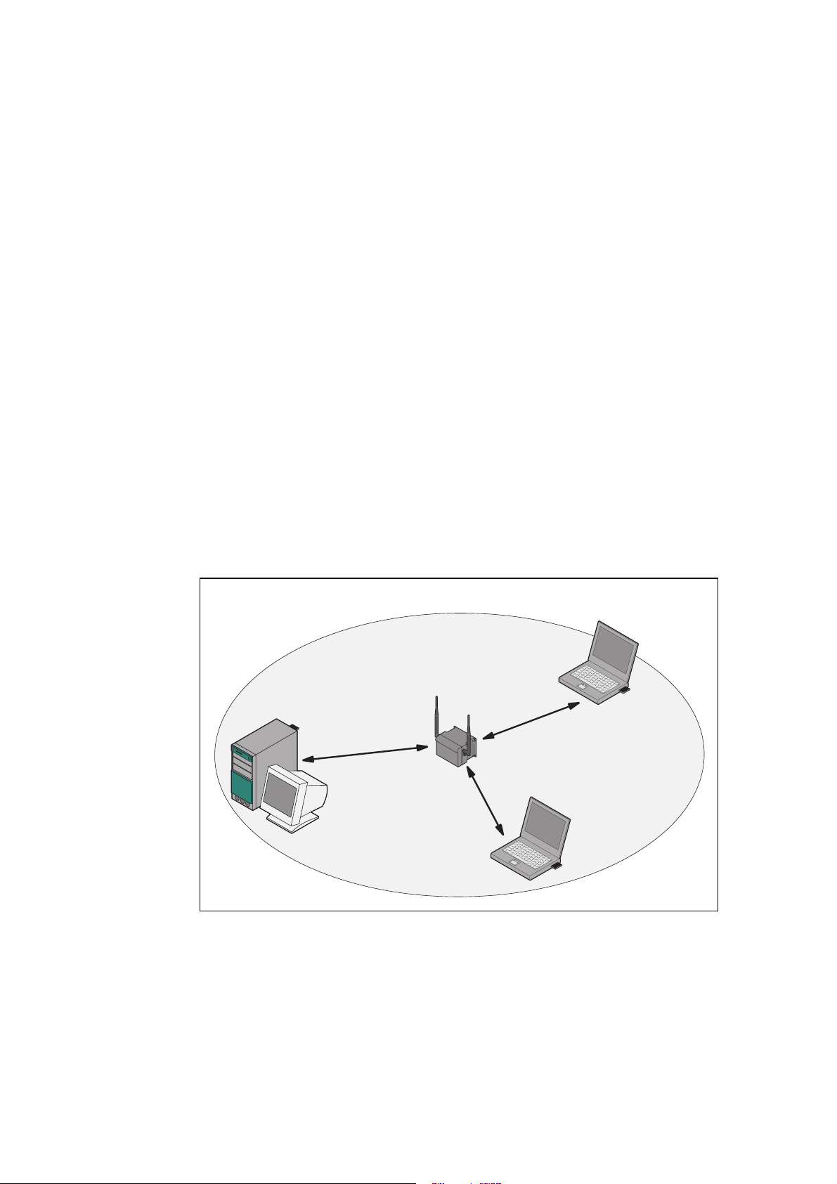
Standalone Configuration with the SCALANCE W78x
This configuration does not require a server and the SCALANCE W78x does not
have a connection to a wired Ethernet. Within its transmission range, the
SCALANCE W78x forwards data from one WLAN node to another.
The wireless network has a unique name. All the devices exchanging data within
this network must be configured with this name.
1
Figure 1-1 Standalone Configuration of a SCALANCE W78x. The gray area indicates
Operating Instructions SCALANCE W78x
C79000-G8976-C184-07
the wireless transmission range of the SCALANCE W78x.
13
Page 14
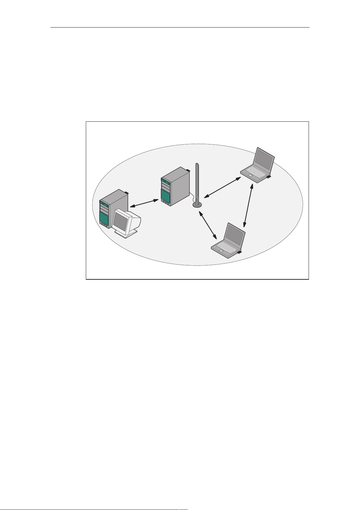
d Hoc Networks
A
In the ad hoc mode, nodes communicate directly (connections 1 through 3 in
Figure 1-2) without involving a SCALANCE W78x with each other (connection 4).
The nodes access common resources (files or even devices, for example a printer)
of the server. This is, of course, only possible when the nodes are within the
wireless range of the server or within each other's range.
Basic Information on Wireless LAN Communication
2
1
3
Figure 1-2 Ad Hoc Network without SCALANCE W 78x
4
Operating Instructions SCALANCE W78x
C79000-G8976-C184-07
14
Page 15
Basic Information on Wireless LAN Communication
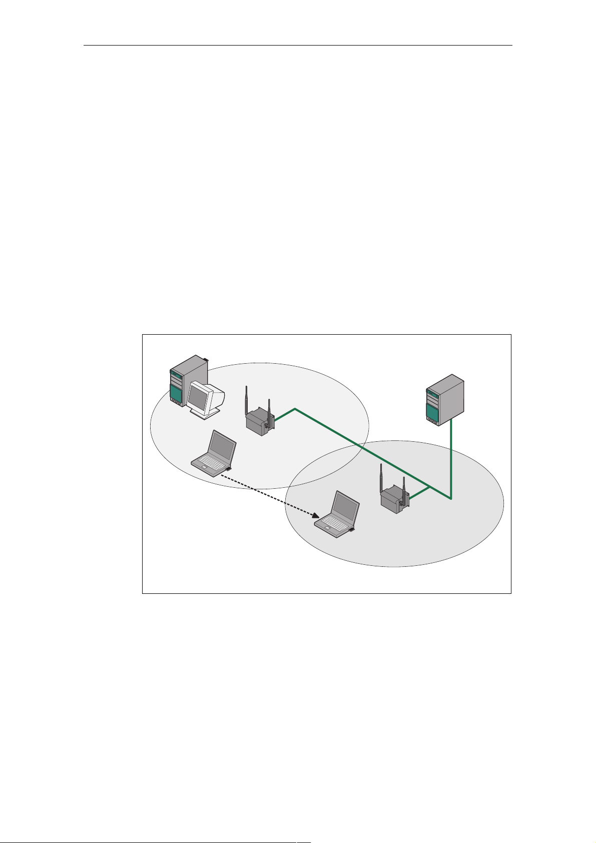
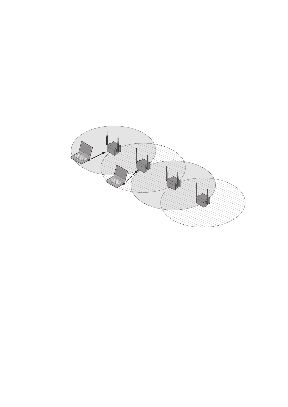
Wireless Access to a Wired E
If one (or more) SCALANCE W78x access points have access to wired Ethernet,
the following applications are possible:
● A single SCALANCE W78x as gateway:
A wireless
network can be connected with a wired network over a SCALANCE
W78x.
● Span of wireless coverage for the wireless network with several
SCALANCE W78x access points:
The SCALANCE W78x acc
SSID (network name). All nodes that want to communicate over this network
must also be configured with this SSID.
If a mobile station moves from the coverage r
SCALANCE W78x to the coverage range (cell) of another SCALANCE W78x,
the wireless connection is maintained (this is called roaming).
thernet Network
ess points are all configured with the same unique
ange (cell) of one
Figure 1-3 Wireless Connection of a Mobile Station over two Cells (Roaming)
Operating Instructions SCALANCE W78x
C79000-G8976-C184-07
15
Page 16
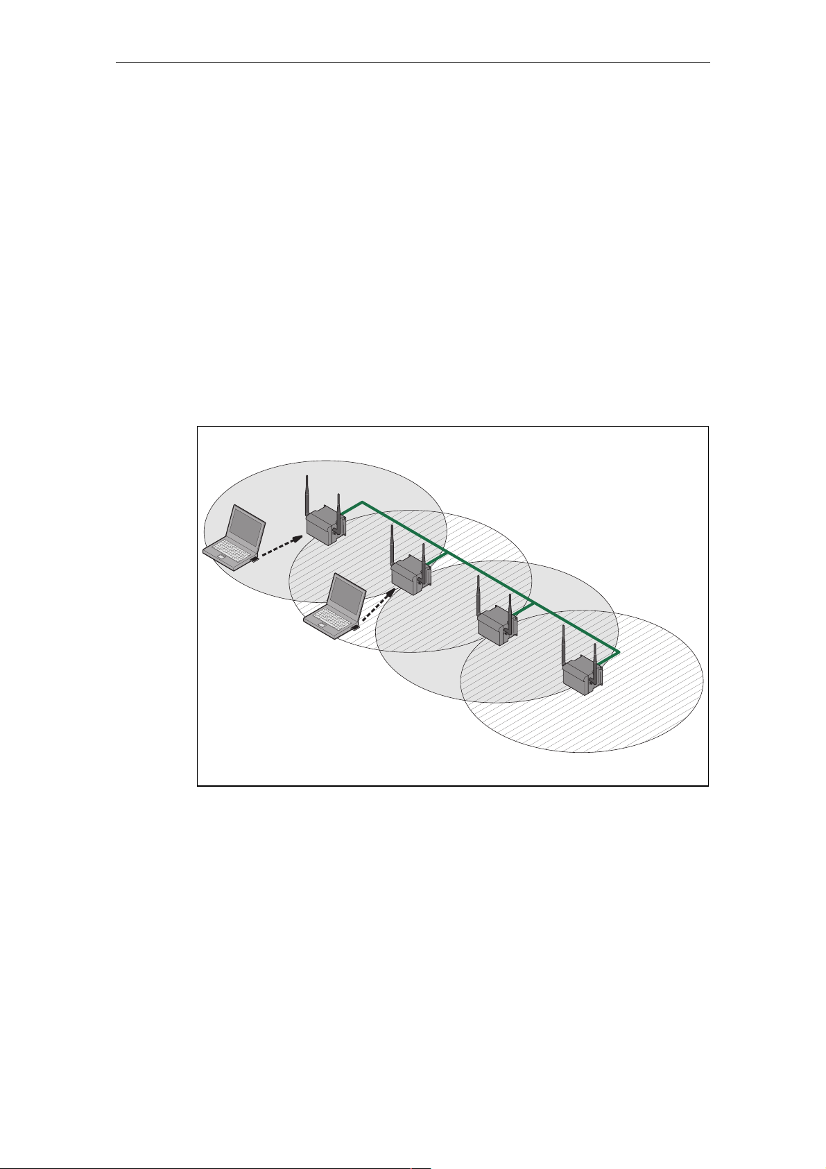
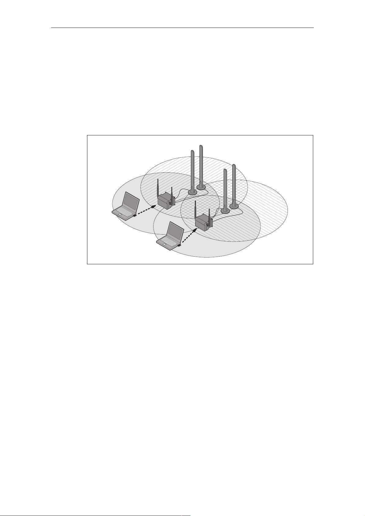
Multichannel Configuration
Basic Information on Wireless LAN Communication
If neighboring SCALANCE W78x access points use the same frequency cha
the response times are longer due to the collisions that occur. If the configuration
shown in Figure 1-4 is implemented as a single-channel system, computers A a
B cannot communicate at the same time with the SCALANCE W78x access po
in their ce
If neighboring SCALANCE W78x access points are set up for different frequencies,
this leads to a considerable improvement in
cells each have their own medium and the delays resulting from time-offset
transmission no longer occur.
Channel spacing should be as large as possible; a practical value would be 25
MHz. Even in a multichannel configuration, all SCALANCE W78x access points
can be configured with the same network name.
lls.
performance. As a result, neighboring
nnel,
nd
ints
1
A
7
1
B
7
Figure 1-4 Multichannel Configuration on Channels 1 and 7 with four
SCALANCE W78x Access Points
Operating Instructions SCALANCE W78x
C79000-G8976-C184-07
16
Page 17
Basic Information on Wireless LAN Communication
Wireless Distribution System (WDS
WDS allows direct connections between SCALANCE W78x devices and or
between SCALANCE W78x and other WDS-compliant devices. These are use
create a wireless backbone or to connect an individual SCALANCE W78x to a
network that cannot be connected directly to the cable infrastructure
location.
Two alternative configurations are possible
both using its name and its MAC address.
1
A
B
)
d to
due to its
. The WDS partner can be configured
1
1
1
Figure 1-5 Implementation of WDS with four SCALANCE W78x Access Points
Operating Instructions SCALANCE W78x
C79000-G8976-C184-07
17
Page 18
Redundant Wireless LAN (RWlan)
RWlan allows a redundant, wireless connection between two SCALANCE W7882xx devices (W788-2PRO or W788
wireless backbone that cannot be
location but nevertheless has high demands in terms of availability.
Basic Information on Wireless LAN Communication
-2RR). This is used to set up a redundant
implemented as a wired network due to its
Two alternative configurations are possible. The RWl
both using its name and its MAC address.
an partner can be configured
B
A
Figu x.
re 1-6 Implementation of RWlan with two SCALANCE W788-2x
As an alternative, data transfer is possible over one of the two wireless
adapters.
Operating Instructions SCALANCE W78x
C79000-G8976-C184-07
18
Page 19

1.2 W
1.2.1 MA
LAN Communication
C-based Communication
Auto Find Adopt MAC / Adopt MAC manually
Frames in the direction from the client to the access point always have th
address of the WLAN interface as the source MAC address. As a result, the
learning table at the access point end always has only the MAC address of the
WLAN interface of the client.
If the MAC address of a device conn
both the MAC-based and the IP-based frames find their destination in precisely thi
device.
Other node
checks whether the destination MAC matches the MAC addresses of the
connected clients. Since a client can only adopt one MAC address, the acc
point does not find a match and discards the packets to other nodes.
Maximum possible number of MA
s located downstream from the client cannot be reached. The AP
ected to the client over Ethernet is adopted,
C nodes downstream from the client: 1
e MAC
s
ess
Notes on setting Auto Find Adopt MAC:
● As long as there is no link on the Ethernet interface, t
address of the Ethernet interface so that it can be reached in this status. In this
status, the device can be found using the Primary Setup Tool.
● As soon as there is a link on the Ethernet interface, the device adopts the
source MAC address o
Note
From the moment that the device adopts another MAC address (whether manually
or automatically), the device no longer responds to queries of the Primary Setup
Tool when the query is received over the WLAN interface. Queries of the PST over
the Ethernet interface continue to be replied to.
f the first received frame.
he device uses the MAC
Adopt Own MAC (only W746/W747 and W788 in client mode)
If IP-based frames need to be sent to a device connected downstream from the
client, the default setting Adopt Own Mac can be retained. The client registers with
the MAC address of its Ethernet adapter. The IP packets are broken down
according to an internal table and forwarded to the connected devices (IP
mapping).
Operating Instructions SCALANCE W78x
C79000-G8976-C184-07
19
Page 20

Basic Information on Wireless LAN Communication
Communication at the MAC address level (ISO/OSI layer 2) is then only possible
with a component downstream from the client if its MAC address was adopted by
the client.
Maximum possible number of MAC nodes downstream from the
Layer 2 Tunneling (only W746/W747 and W788 in client mode)
With layer 2 tunneling, the client provides information about the devices
downstream from it when it registers with an access point. This makes it possible to
enter the MAC addresses of these devices in the learning table of the access point.
The access point can forward MAC-based frames for the devices downstream from
the client to the appro
In much the same way as with WDS, a separate port is created for th
over which the Ethernet frames are sent without changing the destination MAC
address.
Maximum possible num
priate client.
ber of MAC nodes downstream from the client: 8
1.2.2 IP-based Communication
IP Mapping
(only W746/747 and W788 in client mode)
If there is more than one device connected downstream from the client and these
o
sh uld only be addressed with IP frames, you can implement WLAN access for
sev With IP mapping, the client maintains a table with
eral devices with one client.
the assignment of MAC address and IP address to forward incoming IP frame
the correct MAC address.
client: 0
e L2T client
s to
Maximum possible number of IP nodes downstream from the client: 8
Operating Instructions SCALANCE W78x
C79000-G8976-C184-07
20
Page 21

Description of the SCALANCE W78x
2
Componen o
Requirements for Installation and Operation
ts f the Product
The ponents are supplied with the SCALANCE W78x:
following com
● SCALANCE W78x
● 2 OMNI antennas
1 IE IP 67 hybrid plug-in connection
●
● 1 protective cap for the M12 socket
● 2 (or 4 with SCALANCE W788-2PRO or SCALANCE W788-2RR) protective
caps for the R-SMA sockets
● 1 SIMATIC NET Industrial Wireless LAN CD with these Operating Instructions
for the SCALANCE W78x
Please check that the consignment you have received is complete. If it is not
complete, please contact your supplier or your local Siemens office.
A PG/PC with a network attachment must be available to configure the
SCALANCE W78x. If no DHCP server is available, a PC on which the Primary
Setup Tool (PST) is installed is necessary for the initial assignment of an IP
address to the SCALANCE W78x. For the other configuration settings, a computer
with Telnet or an Internet browser is necessary.
Operating Instructions SCALANCE W78x
C79000-G8976-C184-07
21
Page 22

Description of the SCALANCE W78x
Possible Applications of the SCALA
The SCALANCE W78x is equipped with an Ethernet interface and a wireless LAN
inte 88-2RR: two WLAN
rface (SCALANCE W788-2PRO and SCALANCE W7
interfaces). This makes the device suitable for the following applications:
● The SCALANCE W78x forwards data within its transmission range from
node to another without a connection to wired Ethernet being necessary.
●
The SCALANCE W78x can be used as a gateway from a wired to a wireless
network.
The SCALANCE W78x can be used as a wireless bridge between two
●
tworks.
ne
● The SCALANCE W78x can be used as a bridge between two different
frequencies.
Over and above this, due to the second interface of the SCALANCE W788-2PR
and the SCALANCE W788-2RR, a redundant w
implemented between two SCALANCE W788-2xx modules.
NCE W78x
one
O
ireless link can also be
Operating Instructions SCALANCE W78x
C79000-G8976-C184-07
22
Page 23

Description of the SCALANCE W78x
roperties SCALANCE W78x
P of the
● The Ethernet interface supports 10 Mbps and 100 Mbps, both in full and half
duplex as well as autocrossing and autonegotiation.
Operating the wireless interface in the frequency bands 2.4 GHz and 5 GHz.
●
● Th
e wireless interface is compatible with the standards IEEE 802.11a ,
IEEE 802.11b and IEEE 802.11g. In the 802.11a- and 802.11g mode, the
gross transmission rate is up to 54 Mbps. In turbo mode, the Transmission rate
is up to 108 Mbps (not permitted in all countries and modes).
N
ote
If NCE ate (A rbo), remember
the SCALA
that the channels o the set transmission channel are also used for
communic rb n therefo on these channels when there
ation. Distu ances ca re occur
W78x is oper
adjacent t
are neighboring wireless systems. The da hput can also be reduced if
there is com etition for use these hannel
p of c s.
d in turbo mode , G or H tu
ta throug
● As an expansion of the 802.11a mode, it is also possible to op g
erated accordin
to the IEEE 802.11h standard. In 802.11h mode, the procedures Transmit
Powe nd uen n ) are used in
r Control (TPC) a Dynamic Freq cy Selectio (DFS the
range 5.25 - 5.35 and 5.47 - 5.75 GHz. This means that in som the
frequency sub-band 5.47 - 5.725 GHz can also be used outdo er
e countries,
ors with high
transmit power.
TP
C is a method of co ling the transmit power tha redu
c
urrently required level. With dynamic fre ency selec n (DF
point searches for primary users (for example radar) on a rand cted
channel before starting communication. If signals are found on
this ch
annel is disabled and the availability check is repeated on
a
r c
nothe hannel.
The gross transmission rate is up to 54 Mbps in 802.11h mod
● Support of the authentication standards WPA, WPA-PSK, WP
ntrol t is
qu
tio
for 30 minutes
ced to the
S), the access
omly sele
the channel,
e.
A2, WPA2-PSK
and IEEE 802.1x and the encryption methods WEP, AES and TKIP.
● Suitable for
inclusion of a RADIUS server for authentication.
● Device-related and application-related monitoring of the wireless connection.
● The interoperability of SCALANCE W78x dev
ices with Wi-Fi devices of other
vendors was tested thoroughly.
● Only for W78x-1RR/2RR: The iPCF mode provides an optimized data
throughput and minimum handover times.
Operating Instructions SCALANCE W78x
C79000-G8976-C184-07
23
Page 24

Description of the SCALANCE W78x
Note
In the client mode, you can use a SCALANCE W
1RR and a SCALANCE W788-xPRO as SCALANCE
Not
e
For that you enable the iPCF mode.
PNIO communication, we always recommend
The following table illustrates the differences between the various variants of the
SCALANCE W78x:
Type No. of WLAN
interfaces
1 2 1 several
W7881PRO
W7882PRO
W788-1RR
W788-2RR
●
●
●
●
●
No. of
supported IP
nodes
No. of supported
MAC nodes
(3)
1 several
●
● ●
●
●
788-xRR as SCALANCE W747-
W746-1PRO.
iPCF
(3)
mode
●
● ●
●
(1)
Order no.
6GK57881ST00-2AA6
6GK57881ST00-2AB6
6GK57882ST00-2AA6
6GK57882ST00-2AB6
6GK57
1SR00-2AA6
6GK57881SR00-2AB6
6GK57882SR00-2AA6
6GK5788
2SR00-2AB6
88-
(2)
(2)
(2)
-
(2)
(1) The iPCF rovides an ut and minimum handover times.
(2) US varia
(3) In client mode.
mode p
nt
In the SCALANCE HELP
configurat o
Operating Instructions SCALANCE W78x
C79000-G8976-C184-07
ion parameters
W78x
optimized data throughp
function, you will find further inform
f the relevant device.
ation on the
24
Page 25
Description of the SCALANCE W78x
Ports
The SCAL 78x ha
● RJ-45 cto isting of an RJ-
● s optio
● Two R-SMA plugs (fou PRO and
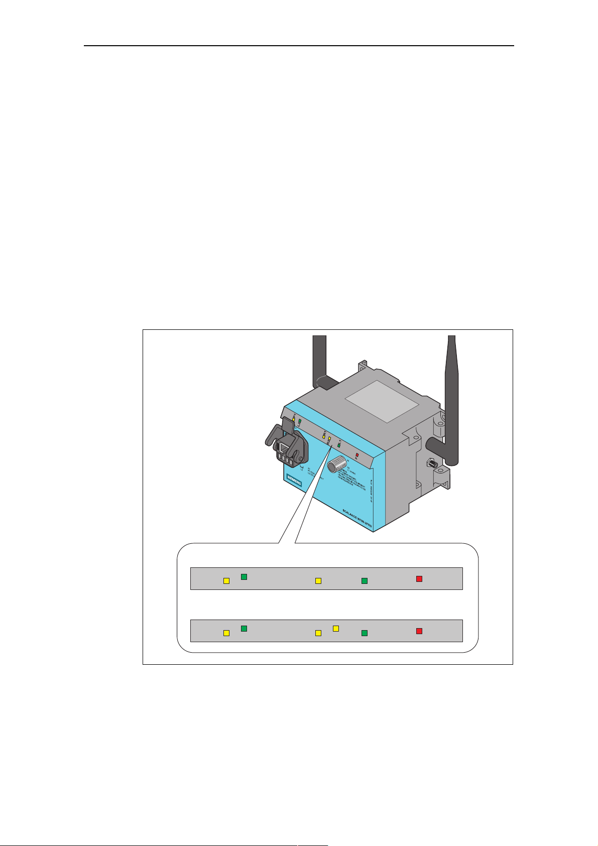
LED Display
On the front of the housing g
status of the SCALANCE W
ANCE W s the following ports:
hybrid conne
45 jack an we s the use of
d 4-pin po
r on the front panel of the housing cons
r socket. The RJ-45 connector support
switches capable of power-over-Ethernet according to 802.3af. The 4-pin
power socket allows power of 18 - 32 V DC.
An M12 connector a nal power supply (18 - 3
2 V DC).
r R-SMA plugs on the SCALANCE W788-2
SCALANCE W788-2R chment of antennas on the sides of the
R) for the atta
device.
, several LEDs provide information on the operatin
78x:
S C A L A N C E W 7 8 8 - 1 x x
S C A L A N C E W 7 8 8 - 2 x x
Figure 2-1 The LEDs of the SCALANCE W78x
Operating Instructions SCALANCE W78x
C79000-G8976-C184-07
P 1
L 2
P 1
L 2
R 1
R 1
L 1
F
L 1
R 2
F
25
Page 26

Description of the SCALANCE W78x
The LEDs have the following significa
LED Color Meaning
P1
L2 Green
R1
Yellow Data transfer over the Ethernet interface (traffic).
Green There is a connection over the Ethernet interface. (Link)
Yellow flashing PRESET-PLUG detected.
Yellow/green PRESET function completed successfully.
Green flashing "Flashing“ enabled over PST.
Power supply over the hybrid connector X1 (PoE or
energy contacts).
Yellow Data transfer over the first WLAN interface.
Green Access Point Mode:
The WLAN interface is initialized and ready for operation.
Client Mode:
There is a connection over the first WLAN interface.
Green flashing Access Point Mode:
The channels are scanned.
Client Mode:
The client is searching for a connection to an access point or
ad hoc network.
Green flashing
quickly
Yellow flashing PRESET-PLUG detected.
Access Point
With 802.11h
primary users before the channel can be used for data traffic
Client Mode:
The client waits for the adopt MAC addr
<Aut
nce:
Mode:
the channel is scanned for one minute for
o Find Adopt MAC> and is connected to no access point.
.
ess due to the setting
Green
3x fast,
1x long
flashing
Yellow/green PRESET function completed successfully.
Clie
nt Mode:
The client waits for the adopt
<Auto Find Adopt MAC> a
nd is connected to an access point.
MAC address due to the setting
LED Color Meaning
R2
Yellow Access Point Mode:
Data transfer over the second WLAN interface.
Client Mode:
The LED is always off because the 2nd interface is not
available in client mode.
Green Access Point Mode:
The WLAN interface is initialized and ready for operation.
Client Mode:
The LED is al
available in client mode.
Green flashing Access Point Mode:
The channels are scanned.
Client Mode:
The LED is always off because the 2nd interface is not
available in client mode.
ways off because the 2nd interface is not
Operating Instructions SCALANCE W78x
C79000-G8976-C184-07
26
Page 27

Description of the SCALANCE W78x
ED Color Meaning
L
Green flashing
quickly
Yellow flashing PRESET-PLUG detected.
Yellow/green PRESET function completed successfully.
L1 Green Power supply over the M12 connector (X2).
F
Red
Access Point Mode:
With 802.11h the channel is scanned for one minute for
primary users before the channel can be used for data traffic.
nt Mode:
Clie
e LED is always off because the 2nd interface is not
Th
available in client mode.
An error occurred during oper
SCALANCE W78x.
ation with the
Not
e
e LED for the WLAN interface is not green when the device starts up, although
If th
tivated, the interface is no
it is ac t ready for operation (interface not initialized).
e main reason for this is usually that during commissioning of the
Th
ANCE W78x products, a wa
SCAL iting time of up to 15 minutes can occur when the
ambient temperature is below zero. The device is ready for operation at the
cified ambient temperature as soon as the LED for the WLAN interface is lit
spe
.
green
Operating Instructions SCALANCE W78x
C79000-G8976-C184-07
27
Page 28

Description of the SCALANCE W78x
Configuration Information on the C-PLUG
The
C-PLUG is used to transfer the configuration of the old device to the new
dev rts up with the C-
ice when a device is replaced. When the new device sta
PLUG, it then continues automatically with exactly the same configuration as the
old device. One exception to this can be the IP configuration if it is set over DHCP
and the DHCP server has not been reconfigured accordingly.
Reconfiguration is necessary if you use WDS or redundancy and use the MAC
addresses and not the sysNames. These functions are then based on the MAC
address that inevitably changes if a device is replaced.
Note
As soon as the device is started with a C-PLUG inserted, the SCALANCE W starts
up with the configuration data on the C-PLUG.
Replacing the C-PLUG
Follow the steps below to replace a C-PLUG in a SCALANCE W78x:
1 Turn off the power to the device.
2 Remove the old SCALANCE W78x from its mounting and open the sealing
screw on the rear with a coin or broad screwdriver.
3 Remove the C-PLUG.
4 Open the sealing screw of the new device in the same way and insert the C-
PLUG of the old device.
5 Replace the sealing screws of both devices.
If a new C-PLUG is inserted in a SCALANCE W78x, the configuration stored locally
on the SCALANCE W78x is saved to the C-PLUG. If an incorrect C-PLUG (for
example from another device or a damaged plug) is inserted, the
SCALANCE W78x signals an error with the red LED. The user then has the choice
of either removing the C-PLUG again or selecting the option to reformat the CPLUG and use it.
Note
It is necessary that the configuration on the C-PLUG was generated with a
firmware version ≤ the firmware version on the destination device.
Example: A C-PLUG with version V3.0 cannot be used for a SCALANCE W78x
with firmware version V2.4.
Operating Instructions SCALANCE W78x
C79000-G8976-C184-07
28
Page 29

Description of the SCALANCE W78x
eset Button
R
The reset button is on the rear of the device directly beside the C-PLUG receptacle
and has several functions:
● Restarting the dev
To restart the device
ice.
, press the Reset button.
● Loading new firmware
(Only if the normal procedure for loading firmware with Load & Save (see
Section. 6.2.10) does not work). This can, for example, occur if there was a
power down during the normal firmware update.
Follow the steps below to load new firmware:
1. Turn off the powe
r to the device.
2. Now press the Reset button and reconnect the power to the device while
hold
ing down the button.
3. Hold down the button until the red fault LED (F) starts to flash after
approximately 2 seconds.
4. Now release the button. The bootloader waits in this state for a new
file that you can download by FTP.
5. Assign an IP address with the Primary Setup Tool.
6. Connect a PC to the SCALANCE W78x over the Ethernet interface.
7. Then enter the co
FTP client. The new firmware should be located in the same fol
mmand "ftp <ip address>“ in a DOS box or use a different
der as the
DOS box.
firmware
8. For the login and password, enter "siemens“. You can now transfer the new
firm
ware with the "put <firmware>“ command.
9. Once the firmware has been transferred completely to the device, the device
is restarted automatically.
● Restoring the default parameters (factory default)
Caution:
All previously made settings are lost!
First, turn off the power to the device. Now press the Reset button and
reconnect the power to the device while holding down the button. Hold down
the
button until the red fault LED (F) stops flashing after approximately 10
seconds and is permanently lit. Now release the button and wait until the
fault LED (F) goes off again. The device then starts automatically with the
default parameters.
Operating Instructions SCALANCE W78x
C79000-G8976-C184-07
29
Page 30

Description of the SCALANCE W78x
● Adopting the configuration data from the PRESET PLUG.
If the d
briefly
evice restarts with a valid PRESET PLUG, by pressing the button
, the configuration data is adopted by the device.
Operating Instructions SCALANCE W78x
C79000-G8976-C184-07
30
Page 31

Commissioning
Com
3.1 Ligh
Notes on Lightning Protection
!
missioning
tning Protection, Power Supply, and Grounding
Warning
Antennas installed outdoors must be within the area covered by a lightning
protection system. Make sure that all conducting systems entering from outdoors
can be protected by a lightning protection potential equalization system.
When implementing your lightning protection concept, make sure you adhere to the
r IEC 62305 standard. VDE 0182 o
A suitable lightning conductor is available in the range of accessories of SI
NET Industrial WLAN:
Lightning Protector LP798-1
3
MATIC
PRO (order no. 6GK5798-1LP00-0AA6)
!
Warning
Installing this lightning protector between an antenna and a SCALANCE W788 is
not adequate protection against a lightning strike. The LP798-1PRO lightening
protector only works within the framework of a comprehensive lightning protection
concept. If you have questions, ask a qualified specialist company.
Note
The requirements of EN61000-4-5, surge test on power supply lines are met only
when a Blitzductor VT AD 24V type no. 918 402 is used
Manufacture
2306 Neumarkt, Germany
9
r: DEHN+SÖHNE GmbH+Co.KG Hans Dehn Str.1 Postfach 1640 D-
Operating Instructions SCALANCE W78x
C79000-G8976-C184-07
31
Page 32

Description of the SCALANCE W78x
Safety extra-low voltage (SELV)
!
Grounding
Warning
The SCALANCE W78x devices are designed for operation with safety extra-low
voltage (SELV). Therefore only safety extra-low voltage (SELV) with limited power
source (LPS) complying with IEC950/EN60950/VDE0805 may be connected to the
power supply terminals.
The power supply unit to supply the SCALANCE W78x must comply with NEC
Class 2 (voltage range 18 - 32 V, current requirement 1 A)
The device may only be supplied by a power supply unit that meets the
requirements of class 2 power sources of the "National Electrical Code, table 11
)". If the power supply is designed redundantly (two separate power supplies),
(b
both m
Exceptions:
• Power supply with PE
• Power supply by a SELV power source (according to IEC 60950) or PELV
ust meet these requirements.
LV (according to VDE 0100-410) is also possible if the
generated rated voltage does not exceed the voltage limits 25 V AC or 60 V DC.
power source (according to VDE 0100-410) without limited power is also
permitted if suitable fire protection measures are taken by:
- Installation in a cabinet or suitable enclosure
- Installation is a suitably equipped, closed room
Caution
There must be no potential difference between the following parts otherwise there
is a risk that the device will be destroyed:
• Ground potential of the power supply and ground potential of the antenna
ground.
• Ground potential of the power supply and a grounded housing.
• Ground potential of the power supply and the ground potential of the device
connected to Industrial Ethernet (for example PC, AS-300, AS-400 etc.)
Connect both grounds to the same foundation earth or use an equipotential
bonding cable.
Power over Ethernet
Connecting several SCALANCE W7xx devices with PoE supply from a common
PoE switch (acting as power supply) is not possible.
Operating Instructions SCALANCE W78x
C79000-G8976-C184-07
32
Page 33

Description of the SCALANCE W78x
3.2 Assembly and Connectors
Securing the Housing
There are two ways of securing the housing:
e the holes in the housing to screw the device to the wall or on a horizontal
● Us
surface.
● Install the SCALANCE W78x on a 90 mm long, vertically mounted piece of
standard rail (S7-300). In this ca
between the wall and SCALANCE W78x. If you want to in
W78x along with a PS791-1PRO, a 150 mm long standard rail is necessary.
Make sure that there is suitable strain relief for the conne
● cting cable.
se, the standard rail serves as an adapter
stall the SCALANCE
t
No e
We recomme
ade. This avoids unwanted heating of the device and prevents premature ageing
sh
the device and ca
of bling. When operating the SCALANCE W outdoors, make sure
that it is installed so that it is protected from UV and that the device is not
to ain (installed under a roof).
r
Note
The minimum distance to fluorescent lamps should be 0.5 m. For cabinet
installation, we recommend that you do not install relays on the same or on directly
neighboring mounting rails.
nd that you protect the device from direct sunlight with a suitable
Connectors for the Power Supply and for Ethernet
The SCALANCE W78x is attached to Ethernet via a hybrid socket on the front of
the housing (position A in Figure 3.1). This port also has contacts for the operating
voltage.
Note
If you do not use the hybrid socket, this must be covered with a protective cap,
otherwise IP 65 protection is lost. A suitable protective cap is available as an
accessory (order no. 6ES7194-1JB10-0XA0). If you do not use the M12 connector,
the supplied protective cap must also be fitted to retain the IP65 degree of
protection.
exposed
Operating Instructions SCALANCE W78x
C79000-G8976-C184-07
33
Page 34

Description of the SCALANCE W78x
D
A
B
Figure 3-1 Connectors of the SCAL
As an alternative or in addition to this, u er
supply (position B in Figure 3.1).
You can fit additional antennas to the
SCALANCE W788-2RR with an anten C in Figure 3.1). If you
install the SCALANCE W78x in a cab
must be unscrewed due to the restric
connection is over detached antenna
panel, there is also an identifier for th
on the right-hand side and B connect
SIMATIC NET offers the IWLAN FRNC antenna extension cable for the connection
between the SCALANCE W78x and detached antenna. To avoid violating the
approvals, only antennas released for this product can be used.
Note
T a pair of antennas for the first and se
he distance between
m
ust be at least 0.5 m.
ANCE W78x
yo can also use the M12 plug for the pow
sides of the SCALANCE W788-2PRO and
na cable (position
inet, the antenna (position D in Figure 3.1)
ted communication. In this case, the
s in store outside the cabinet. On the front
e antenna connectors. The A connectors are
ors B on the left-hand side.
C
cond WLAN interface
Operating Instructions SCALANCE W78x
C79000-G8976-C184-07
34
Page 35

Description of the SCALANCE W78x
3.3 Cabling for Power Supply a
3.3.1 General Notes
Suitable Cables
The following cable variants are available to connect a SCALANCE W78x to the
power supply and to Ethernet:
● IE hybrid cable 2 x 2 + 4 x 0.34 (o
The two data wire pairs are separa
suitable for assembly with the IE IP 67 hybrid co
● IE FC TP standard cable 4 x 2 GP
IE FC TP flexible cable 4 x 2 GP ( -2H)
In these cable types, two wires are twisted. All four pairs of wires are inside a
common shield.
● 2 x 2 IE cable, the optional power supply (18 - 32 V DC) is over M12
connectors.
nd Ethernet
rder no. 6XV1870-2J)
tely shielded. This cable is particularly
nnector.
(order no. 6XV1870-2E)
order no. 6XV1870
Cable Selection and Interference Exposure
A decisive factor in the selection of a e
to which the current lines between the dular
outlet are subjected. Due to the separ
interference has less effect on the dat
standard cable or TP flexible cable.
A B C
Figure 3-2 Cabling a SCALANCE W Interference between
the Power Supply and M
A Power supply
B FC RJ-45 modular outlet with power insert
C SCALANCE W78x
cable type is the electromagnetic interferenc
power supply and the FC RJ-45 mo
ate shielding of the data wires, such
a transmission on a hybrid cable than on TP
7xx with Electromagnetic
odular Outlet
Operating Instructions SCALANCE W78x
C79000-G8976-C184-07
35
Page 36

Description of the SCALANCE W78x
3.3.2 Assembling an IE Hybrid Cable
Hybrid Connector
2 x 2 + 4 x 0.34 with an IE IP 67
Remove the two inner shells of the
universal sealing ring to adapt it to
the diameter of the hybrid cable.
Push the bushing, washer, adapted
universal sealing ring and the
housing over the cable jacket.
Remove the following lengths of
ble jacket and shield braid:
ca
• 25 mm for the power lea
• 30 mm jacket for the data lead
(shorten the braid by 11 m
ds.
s
m).
Cut off the filler at the height of the
cable jacket.
Arrange the data leads according to
the color codes on the splice
hows element. The following table s
the assignment of the data leads.
Contact and color assignment of the
splice element.
Operating Instructions SCALANCE W78x
C79000-G8976-C184-07
36
Page 37

Description of the SCALANCE W78x
Wire color code
(standard)
Connector color
code (Siemens IE)
Siemens IE FC RJ45 socket
(reference)
White Blue Yellow Orange
White Blue Yellow Orange
3 6 1 2
Insert the all the data leads at the
same time into the splice element is
far as they will go.
Cl se the splice element o and RJ-45
data module until they lock together.
Insert the data module and the
splice element into the supplied IDC
assembly tool.
Press the data module and the IDC
assembly tool together to establish
the installation piercing connection.
Operating Instructions SCALANCE W78x
C79000-G8976-C184-07
37
Page 38

Description of the SCALANCE W78x
Remove the assembled data
module from the IDC assembly tool.
Position the top shield plate and
press it over the cable shield.
Position the lower shield plate and
press it and the upper shield plate
together until they lock together with
an audible "click".
Wire color code
(standard)
Power supply insert
module
Arrange the power leads and insert
them as far as they will go into the
hinge elements of the isolation body.
The following table shows the
assignment of the power leads.
Brown Brown Black Black
24 V 24 V Ground Ground
1 2 3 4
Operating Instructions SCALANCE W78x
C79000-G8976-C184-07
38
Page 39

Description of the SCALANCE W78x
Press each individual hinge element
together with the integrated IDC
contact.
Recommendation: Use a small
slotted screwdriver (max. 3.5 mm
)
as a lever.
Push the housing over the
assembled data module and the
ulator body until they lock
ins
together (there should be an audible
click).
Tighten the cable gland. We
recommend an open ring key with a
size of 21 mm.
Operating Instructions SCALANCE W78x
C79000-G8976-C184-07
39
Page 40

Description of the SCALANCE W78x
3.3.3 Assembling an IE FC TP Standard Cable 4 x 2 GP or IE FC TP Flexible Cable 4 x 2 GP with an IE IP 67 Hybrid Connector
Remove the two inner shells of the
universal sealing ring to adapt it to
the diameter of the hybrid cable.
Push the bushing, washer, adapted
universal sealing ring and the
housing over the cable jacket.
Remove the following lengths of
cable jacket and shield braid:
• 25 mm for the power leads.
• 30 mm for the data leads.
To achieve good shielding, the shield
braid must be alt least 30 mm long.
Arrange the data leads according to
the color codes on the splice
element. The following table shows
the assignment of the data leads.
Wind the shield braid around the data
leads. As a result, the shielding of the
cable has contact to the shield plate
of the splice element that will be fitted
later.
Contact and color assignment of the
splice element.
Operating Instructions SCALANCE W78x
C79000-G8976-C184-07
40
Page 41

Description of the SCALANCE W78x
Color Coding of the White /
Standard Cable
Connector color
code (Siemens IE)
Siemens IE FC RJ45 socket (reference)
Orange *
White
3 6 1 2
* White wire of the particular pair.
Insert the all the data leads at the
same time into the splice element is
far as they will go.
Close the splice element and RJ-45
Orange
Blue
White /
Green *
Yellow
Green
Orange
data module until they lock together.
Insert the data module and the splice
element into the supplied IDC
assembly tool.
Press the data module and the IDC
assembly tool together to establish
the installation piercing connection.
Operating Instructions SCALANCE W78x
C79000-G8976-C184-07
41
Page 42

Description of the SCALANCE W78x
Remove the assembled data module
from the IDC assembly tool.
Position the top shield plate and
press it over the cable shield.
Position the lower shield plate and
press it and the upper shield plate
together until they lock together with
an audible "click".
Arrange the power leads and insert
them as far as they will go into the
hinge elements of the isolation body.
The following table shows the
assignment of the power leads.
Wire color code
(standard)
Power supply insert
module
White /
Blue *
24 V 24 V Ground Ground
1 2 3 4
* White wire of the particular pair.
Blue
White
brown *
Brown
Operating Instructions SCALANCE W78x
C79000-G8976-C184-07
42
Page 43

Description of the SCALANCE W78x
Press each individual hinge element
together with the integrated IDC
contact.
mmendation: Use a small
Reco
slotted screwdriver (max. 3.5 mm) as
a lever.
Push the housing over the
assemb
led data module and the
insulator body until they lock together
(there should be an audible click).
Tighten the cable gland. We
ith a recommend an open ring key w
size of 21 mm.
.3.4 Pinout of the M12 Connector 3
X2 Socket
PIN 1 24 V DC
PIN 2 -PIN 3 Ground
PIN 4 --
Operating Instructions SCALANCE W78x
C79000-G8976-C184-07
43
Page 44

Description of the SCALANCE W78x
.4 Commissioning with the PRESET PLUG
3
How
It Works
Creating a
With the PRESET PLUG, it is simple to assign a configuration
such as access points, EC
configuration to any numbe
procedure is particularly useful when commissioning a lot of WLAN clients with the
same parameter settings because you do not need to set parameters for each
client manually.
Note
To avoid duplicating IP addresses, the IP parameters are not changed but are
retained when you use the PRESET PLUG.
If the PRESET PLUG is inserted, the W
WLAN operation with a PRESET PLUG
Note
With a version V3.0 AP or older, it is not possible to create a PRESET-PLUG for
the IWLAN/PB-Link versio
update the IWLAN/PB Link to firmware V1.2, the configuration is available aga
a PRESET PLUG (created with V3.1).
Ms or IWLAN/PB links. You transfer an existing
r of other devices using the PRESET PLUG. This
LAN interface of the device is deactivated.
insert it is not possible.
n V1.1. Please use a version V2.4 AP or older. If you
to WLAN devic
es
in on
Configuration with a new PRESET-PLUG
Follow the steps below to save a configuration on a PRESET PLUG:
1. Insert the PRESET PLUG in the C-PLUG slot of a powered-down device with
the required configuration and then turn on the device.
2. Start Web Based M
3. In the Modify C-PLUG list box, select the Create PRESET-PLUG entry.
anagement and select the System > C-PLUG menu.
Operating Instructions SCALANCE W78x
C79000-G8976-C184-07
44
Page 45

Description of the SCALANCE W78x Description of the SCALANCE W78x
4. In the PRESET PLUG for box, specify the device for which you want to create
the PRESET PLUG.
Note
A PRESET PLUG for configuring a SCALANCE W78x in Access Point mode
must be created with a SCALANCE W78x because a SCALANCE W74x does
not have all the configuration settings required for the W78x.
5. Click on the Modify button to transfer the configuration of the device to the
PRESET PLUG.
6. Turn the device off and remove the PRESET PLUG.
Operating Instructions SCALANCE W78x
Operating Instructions SCALANCE W78x
C79000-G8976-C184-07 C79000-G8976-C184-07
45
45
Page 46

Description of the SCALANCE W78x
Changing a used PRESET PLUG
1. Insert the PR
W7xx and then turn on the device. The P1 and R1 LEDs flash yellow to signal
that the PRESET PLUG was
2. Start Web Based Management, there you will see the current settings of the
PRESET PLUG. Make the required changes to the configuration.
3. In the Modify C-PLUG list box, s RESET-PLUG entry.
In the PRESET PLUG for box, specify the device for which you
4. want to create
the PRESET PLUG.
Click on the Modify button to transfer the configuration o
5. f the device to the
PRESET PLUG.
6.
Turn the device off and remove the PRESET PLUG.
Using the vice
PRESET PLUG to commission a de
Note
To work correctly, the PRESET PLUG must have a content that matches the target
device.
ESET PLUG in the C-PLUG slot of a powered-down SCALANCE
detected.
elect the Create P
1. Insert the PRESET PLUG in the C-PLUG slot of the device to which you wan
to assign a configuration.
2. Turn on the power to the device. The LEDs P1 and R1 (and R2 on a
SCALAN
PRESET PLUG was detected.
3. Press the reset button beside the C-PLUG briefly to save the settings of the
PRESET PLUG on the device.
4. When all the data has been transferred from the PRESET PLUG to the
device, the LEDs stop flashing and are permanently lit.
5. Turn the device off and remove the PRESET PLUG.
Note
The next time the device starts up, it uses the settings from the PRESET PLUG
and the previous IP configuration.
CE W7xx with two wireless interfaces) flash yellow to signal that the
t
Operating Instructions SCALANCE W78x
C79000-G8976-C184-07
46
Page 47

Configuring the IP Address with the
Primary S
etup Tool
4.1 Introduct
Primary Se
tup Tool on CD and the Internet
The ool is on the CD that ships with the SCALANCE W78x.
Primary Setup T
The Primary Setup Tool is also available from Siemens Aut
Service & Support on the Internet under entry ID 19440762. You will find this entry
under the following URL:
http://support.automation.siemens.com/WW/view/en/19440762
Note
On the CD and on the Internet, you will find the latest version of the Primary Setup
Tool (at the time of release of this document, Version 3.1). Make sure that you use
the version V3.1 or higher for the SCALANCE W78x.
4
ion
omation and Drives
Operating Systems Supported
The Primary Setup Tool can be installed and used with the following operating
systems:
● Windows XP Professional
● Windows 2000 Professional SP2
Operating Instructions SCALANCE W78x
C79000-G8976-C184-07
47
Page 48

DLC Protocol
The Primary Setup Tool uses the DLC protocol for communication with the
module
throug
● Windows XP Professional
● Windows 2000 Professional SP2
Configuring the IP Address with the Primary Setup Tool
s. Depending on the operating system you are using, you must work
h the following steps before you can use the DLC protocol:
The DLC protocol is not supplied with Windows XP and must be installed and
activated separately.
The DLC protocol is supplied with Windows 2000 but must be added to the
active protocols.
Note
The sections on installing the DLC protocol are relevant only for older firmware
ions < V2.3.
vers
Operating Instructions SCALANCE W78x
C79000-G8976-C184-07
48
Page 49

Configuring the IP Address with the Primary Setup Tool
4.2 Installation of the DLC Protocol in Win
Professional
Extracting the Archive File
The files for installing the DLC protocol are in the self-extracting ZIP archive
pst_install.exe. Fo
1. Double-click on the file name pst_install.exe in the Windows Explorer or start
the program using t
2. In the dialog box of the extraction program, select the folder into which you
want to extract the files and click on the Extract button.
Installation
Follow the step
1. Double-click on the setup.exe file.
2. In the Choose Setup Language dialog, select the language you want to use.
3. Click on the Next button in the first dialog.
llow the steps below to extract the files from the archive:
he Windows menu command Start > Run.
s below to install the DLC protocol on your computer:
dows XP
4 In the next dialog, select the folder in which you want to install the program
and click on the Next button to confirm your selection.
5. Close the last dialog of the installation program by clicking on the Finish
button.
Operating Instructions SCALANCE W78x
C79000-G8976-C184-07
49
Page 50

Configuring the IP Address with the Primary Setup Tool
4.3 Installation of the DLC Protocol in Windows 2000 Professional SP2
Follow the steps below to install the DLC protocol on your computer:
1. Select the menu command Start > S
Dial-Up Connections.
2. Select the connection to your Ethernet communications module.
Right-click to open the context menu and select Prop
3. erties.
4. Click on the Install... button in the General tab.
In the Select Network Component Type dialog, select the entry Protocol an
5. d
click the Add... button.
In the Network Protocols window, select the entry DLC Protocol and con
6. firm
by clicking OK.
7. Close the properties dialog by clicking the OK button.
ettings > Control Panel >Network and
Operating Instructions SCALANCE W78x
C79000-G8976-C184-07
50
Page 51

Configuring the IP Address with the Primary Setup Tool
4.4 In
Procedure
stalling the Primary Setup Tool
Follow the r:
1. ws Explorer or start the
Double-click on the file name setup.exe in the Windo
program using the Windows menu command Start > Run.
2. In th
wan
3. The first dialog box of the Installation Wizard opens. Click on the Next button.
4. The dialog box for selecting the installat
button if you want to accept the default C:\Program Files\Siemens\P
Setup Tool\. If you want to use a different folder, you can open a dia
sele
S
5. If the DLC protocol is not installed on your computer, the Information dialog
open OK and install
t
steps below to install the Primary Setup Tool on your compute
e Choose Setup Language dialog box, select the language in which you
t to run the installation.
ion folder opens. Click on the Next
rimary
log box to
ct the folder by clicking the Browse button.
tart the installation by clicking the Next button.
s referring you to the ReadMe file. Confirm the dialog with
he DLC protocol later as described in the ReadMe file.
A final dialog box informs you that the installation was succe
6. ssful. Click on the
Finish button to close this dialog box.
After installation of PST V3.1, start the tool with Start > SIMATIC > Primary Setup
Tool.
Operating Instructions SCALANCE W78x
C79000-G8976-C184-07
51
Page 52

Configuring the IP Address with the Primary Setup Tool
4.5 Working with the Prim
Selecting t
Selecting the Network Adapter
Browsing the Network
he Language
After a elect the
st rting the Primary Setup Tool, a dialog opens in which you s
langu >
age for the program. You can also set the language in the Settings
uage menu.
Lang
If there is more than one network adapter in your computer, you can open the
Settings > Network Adapter menu and specify which adapter is used by the
Primary Setup Tool. This menu displays a maximum of four network adapters.
Before you assign IP addresses with the PST, you must first locate the
configurable devices in the network. Start this search with the steps outlined belo
● Select the Network > Browse menu command.
ary Setup Tool
w:
● Press th
● Click on the magnifier icon in the toolbar below the menu bar.
While the Primary Setup Tool browses the network, the Browse Network dialog is
displayed with a progress bar. On completion of the search, the Primary Setup Tool
displays a list with all the devices it has found in the left-hand pa
e F5 key.
ne.
Operating Instructions SCALANCE W78x
C79000-G8976-C184-07
52
Page 53
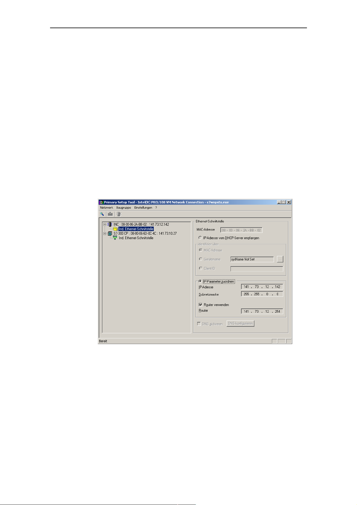
Configuring the IP Address with the Primary Setup Tool
Configu
ring a Module
If you click an entry in the list, the Primary Setup Tool displays information on the
selected device in the right-hand pane.
Follow the steps below to configure a device:
1. Click on the plus symbol in front of the device symbol or doub
device symbol to display all interfaces of the device.
2. Click on the interface you want to configu
re. The Primary Setup Tool displays
the input dialog for the configuration data in the right-hand pane of the
m window. Depending ed settings, some or
progra
check boxe
because this addre t cannot be modified.
Moreover, the Client-I re not supported by the
SCALANCE W7xx
s may x s alwa
ss is a property of the device tha
D and DNS parameters a
.
on the select text boxes
i
le-click on the
ys disabled be disabled. The MAC address bo
3. Decide how the device will obtain its IP address:
● Dynamically from a DHCP server:
Select the Obtain IP address from DHCP server option button.
● Manual assignment by the user:
Select the Assign IP parameters option button.
Operating Instructions SCALANCE W78x
C79000-G8976-C184-07
53
Page 54

Configuring the IP Address with the Primary Setup Tool
4. Make the following entries if you have decided to assign the IP address
manually:
● Enter the IP address for the device in the IP Address box. In each pa
and 255; the program does not accept any other num
● Enter the subnet mask in the
Subnet Mask box.
● If necessary, select the Use router check box and enter the IP address of
the router in the text box. Router information is necessary if the computer
on which you are creating the configuration is not in the same subnet as
the device to be configured.
Downloading Configuration Data to the Module
Follow the steps below to transfe
1. Select the module you want to configure in the left pane of the program
window. As long as an interface is selected and the input dialog for the
configuration data is displayed, no download of the configuration
possible.
2. Start the download by following the steps outlined below:
● Select the Module > Download menu command.
r the configuration data to the device:
a number betwe
bers.
data is
rt of
en 0 the address separated by the periods, you can enter
● Click on the second button
from the left in the toolbar.
Operating Instructions SCALANCE W78x
C79000-G8976-C184-07
54
Page 55

tarting W sed Management
S eb Ba
INCs (Industrial Network Components) such as a SCALANCE W7xx include Web
Based Management. Select the device you want to configure with Web Based
Management and follow the step
● Select the menu command Module -> Start INC Browser.
● Click on the third icon from the left in the toolbar (module with four blue
wires).
Configuring the IP Address with the Primary Setup Tool
s below to start Web Based Management:
If the Module > Start INC Browser and the module icon are disabled, there is no
Web Based Management for the selected module.
Removing a Module
You can remove a module from the list in the left-hand pane of the program
window by selecting the Module > Remove Module menu command. Using this
menu command has no effect on the existence of a module in the network; if you
browse the network again, all modules are displayed again.
Operating Instructions SCALANCE W78x
C79000-G8976-C184-07
55
Page 56

Configuring the IP Address with the Primary Setup Tool
4.5.1 Primary Setup Tool via the Command Line
Syntax
You can al
The syntax is as follows; optional parameters are shown in square brackets:
wnpstx MAC address -DHCP[=client ID]
s7
wnpstx MAC address -RESET
s7
s
7wnpstx MAC address IP address subnet mask [router address]
s
7wnpstx -NAME=station name [index network adapter][INC]
The following table explains the parameters:
Co
MAC address
-DHCP
client ID
-RESET
IP add ss
re
subnet mask
Router address
-NAME
station nam
Index netw
e
ork adapter
INC
so use the Primary Setup Tool from the command line of a DOS prompt.
mmand Description Comment
The MAC address of the module to
be configured.
Specifies that the IP address is
obtained from a DHCP server.
nique identifier for the device. If
A u
this parameter is not specified, the
Primary Setup Tool uses the M
address as the ID.
Sets the IP address to 0.0.0.0 .
The ne
w IP address of the module to
be con
figured.
The new subnet mask of the module
to be configured.
The new IP address of the default
router.
Parameter for setting the station
name.
The station name assigned to the
module. Maximum length 255
characters (letters, numbers, slash,
hyphen, and underscore).
The index of the network ada
The default is "0".
Identifier for a network component. Optional.
AC
pter.
Optional.
Optional.
Optional.
Operating Instructions SCALANCE W78x
C79000-G8976-C184-07
56
Page 57

Configuration Using the Wizards of
Web B
5.1 In
Principle of We
ased Management
troduction
The SCALANCE W78x has an integrated HTTP server for Web Based
Management. If the SCALANCE W78x is accessed by an Internet browser, it
returns HTML pages to the client computer depending on user input.
Users enter the configuration data in the HTML pages sent by the
SCALANCE W78x. The SCALANCE W78x evaluates this information and
generates response pages dynamically.
The great advantage of this method is that apart from a Web browser, no special
software is required on the client.
5
b Based Management
Requirements for Web Based Management
Once you have assigned an IP address with the Primary Setup Tool, you can
continue to configure the device with Web Based Management.
To use Web Based Management, you should ideally have a wired network
connection between the SCALANCE W78x and the client computer. In principle, it
is possible to use Web Based Management over a wireless network, however the
SCALANCE W78x can be set so that access over a wireless network is disabled.
We recommend that you use the Microsoft Internet Explorer Version 5.5 or higher
or Mozilla Firefox Version 1.5 or higher.
All the pages of Web Based Management require JavaScript. Make sure that your
browser settings allow this.
Since Web Based Management is HTTP-based on, you must allow access to Port
80 or Port 443 for HTTPS if you have a firewall installed.
Operating Instructions SCALANCE W78x
C79000-G8976-C184-07
57
Page 58

Configuration Using the Wizards of Web Based Management
Note
The screenshots in this section were created using the Microsoft Internet Explor
version 6.0. If you use a different browser (for example Mozilla), the appearan
ce of
er
the menus may differ.
Operating Instructions SCALANCE W78x
C79000-G8976-C184-07
58
Page 59

Configuration Using the Wizards of Web Based Management
5.2 Starting Web Bas
Procedure
1. In the address box of the Web browser, enter the IP address or the URL of the
SCALANCE W78x. If there is a problem-free connection to the
SCALANCE W78x, the Logon dialog of Web Based Management is displayed:
ed Management and Logging On
2. In the "User Name" list box, select the "Admin" entry if you want to change
settings of the SCALANCE W78x (read and write access). If you select the
"User" entry, you only have read access to the configuration data of the
SCALANCE W78x.
3. Enter your password. If you have not yet set a password, the default passwords
as shipped apply: Enter admin if you selected "admin" as the user name or user
if you selected "user".
4. Click on the "Log On" button to start the logon.
Operating Instructions SCALANCE W78x
C79000-G8976-C184-07
59
Page 60

Configuration Using the Wizards of Web Based Management
5.2.1 Co
Descriptio
nnection over HTTPS
n
Web Based Management also allows you to connect to the device over the secure
connection of the HTTPS protocol.
Enter https:// in the address field of the Internet browser and the IP address o
SCALANC
and asks you whether you want to continue the action. Confirm with YES. The
Login dialog of Web Based Management opens.
E W7xx and confirm with Enter. The warning Security Alert is displayed
f the
Operating Instructions SCALANCE W78x
C79000-G8976-C184-07
60
Page 61

Configuration Using the Wizards of Web Based Management
5.3 Selecting the W
Basic Wizard
Wizard Status
, Security Wizard and iPCF-Wizard
Web Based Management provides several wizards that allow straightforward
commissioning w
consists of a series of dialogs in which you enter the basic configuration data.
There is a wizard for general settings to ensure the basic functionality of the
SCALANCE W78x. The wizard for the security settings supports you when setting
security-related parameters. A further wizard is available in client mode to
configure the iPCF mechanism (industrial Point Coordination Function).
After selecting the "Wizards" menu on the left-hand side of the dialog, the status of
the wizards is displayed. If you have worked through a wizard completely, Done is
displayed as the status. If you have worked through all wizards, the Wizards entry
moves to the bottom end of the menu.
ithout detailed knowledge of wireless technology. A wizard
izards
Operating Instructions SCALANCE W78x
C79000-G8976-C184-07
61
Page 62

Configuration Using the Wizards of Web Based Management
Note
Some pages of the Wizards have a different content in access point mode and
client mode. In this
case, there is a separate description for the alternatives.
You can specify the mode in the System menu.
Operating Instructions SCALANCE W78x
C79000-G8976-C184-07
62
Page 63

5.4 Basic Wizard
Configuration Using the Wizards of Web Based Management
5.4.1 IP
Descriptio
Settings
n
One of the basic steps in configuration of an Ethernet device is setting the IP
address. The IP address identifies a device in the network uniquely. On this page,
you enter the information for IP configuration of the SCALANCE W78x.
Specified I
IP Address
Operating Instructions SCALANCE W78x
C79000-G8976-C184-07
P Address / DHCP Server Option buttons
There are two methods of assigning IP addresses to
be set as a fixed permanent address or can be obtained dynamically from a DHCP
server. Select "
Specified IP Address" if you do not use a DHCP server.
input box
The IP address of the SCALANCE W78x. Here, you enter an address that is
unique within the network.
devices: The IP address can
63
Page 64

Subnet Mask input box
The subnet mask specifies the range of addresses within which communication
ca
n take place.
The four numbers of an IP address separated by periods are interpreted as a bit
pattern. If a one is set at a bit position within the subnet mask, this means that onl
devices with an IP address the matches the IP address
Management Agent at this bit position can communicate with the
SCALANCE W78x.
Example
Let us assume that the IP address of the SCALANCE W78x is set to
192.168.147.189 and the subnet mask is set to 255.255.255.0. The bit pattern for
255 is 1111 1111. This means that the bit pattern of the first number of the IP
address of a comm
W78x exactly at this point. The same applies to the second and third parts of the IP
address. The IP address of a communication partner must therefore start with
192.168.147. The bit pattern of 0 is 0000 0000. This means that the bit pattern of
the last part of the IP address of the partner device does not need to match the
address of the SCALANCE W78x at any point; in other words, it can be any
number.
Configuration Using the Wizards of Web Based Management
y
of the SCALANCE W78x
unication partner must match the bit pattern of the SCALANCE
Operating Instructions SCALANCE W78x
C79000-G8976-C184-07
64
Page 65

5.4.2 System name
Description
The device name also identifies a network node but means more to the user than
the IP address.
Configuration Using the Wizards of Web Based Management
System Nam
In this box, you enter the device name for your SCALANCE W78x. This parameter
corresponds to the sysName SNMP parameter. The device name can be up to
maximum of 255 characters long. If you also want to use this parameter for WDS
or redundancy, the maximum length is 32 characters.
e text box
a
Operating Instructions SCALANCE W78x
C79000-G8976-C184-07
65
Page 66

Configuration Using the Wizards of Web Based Management
5.4.3 Country Co
Descriptio
Note
The correct country setting
approvals. Selecting a co
prosec
ution!
n
Some divisions for WLAN communication.
countries have different frequency band
The regulations for maximum output power also differ from country to country.
When you configure the SCALANCE W78x, you must s
regula
tions are relevant for your location. You do this with the Country code
param
eter.
de
is mandatory for operation complying with the
untry different from the country of use can lead to legal
pecify which local
Country code list box
In this list box, you select the country in which the SCALANCE W78x will be
operated. You do not need to know the data for the specific country, the channel
division and output power are set by the SCALANCE W78x according to the
country you select.
Operating Instructions SCALANCE W78x
C79000-G8976-C184-07
66
Page 67

Configuration Using the Wizards of Web Based Management
5.4.4 Wireless Settings in Access Point Mode
Description
On this page, you specify the configuration of the wireless network. This includes
the network name and the transmission mode. If you are configuring the
SCALANCE W788-2PRO and SCALANCE W788-2RR models, this page ap
a second time t
make different settings for "WLAN1" and "WLAN2".
o allow you to configure the second wireless adapter. You can
pears
SSID text box
Enter the name of your network in this box. The SCALANCE W78x allows all
characters except the percent character for the SSID. To ensure compatibility with
partner devices, you should, however, not use any characters that are peculiar to a
particular language (for example special German characters ä, ö etc.). The string
for SSID can be a maximum of 32 characters long.
Wireless Mode list box
Select a wireless mode that is supported by all partner devices. On the
SCALANCE W788-2PRO and SCALANCE W788-2RR, it may be a practical to set
a different transmission mode for each wireless adapter to allow optimum support
of different clients. The effect of the 802.11.b + g setting is that all the settings in
the Advanced G menu are taken into account as far as possible but that
compatibility with devices conforming to IEEE 802.11 b guaranteed.
Operating Instructions SCALANCE W78x
C79000-G8976-C184-07
67
Page 68

Configuration Using the Wizards of Web Based Management
5.4.5 Wireless Settings in Client Mode
Description
In the Client mode, there is also the check box Connect to ANY SSID. The ot
settings correspond to those of the access point mode.
her
Connect to ANY SSID Check Box
When this check box is selected, the client connects to the access point that allows
the best possible data transfer and to which a connection is permitted based on the
security settings.
Operating Instructions SCALANCE W78x
C79000-G8976-C184-07
68
Page 69

Configuration Using the Wizards of Web Based Management
5.4.6 Adopt MAC Ad
Assigning
the MAC Address
A MAC address must be specified for the device connected to the Eth
the SCALANCE W78x client before it can be reached. This MAC address is used
by the
client for wireless communication with the access point.
● If there is precisely one MAC address to be served downstream from the clie
there are two ways of doing this:
– Automatically, the client adopts the source MAC address of the first frame
that it receives over the Ethernet interface.
– Manual entry by the user.
These settings have no effect on communication with standard Wi-Fi device
● If up to eight M
the following setting is available for SCALANCE W746-1PRO and SCALANCE
W747-1RR:
– Layer 2 Tunneling
This setting meets the requirements of industrial applications in which MAC
address-based communication with several devices downstream from the client
is required. Clients with this setting cannot connect to standard Wi-Fi devices
and SCALANCE W access points with firmware V3.0 or older.
dress Settings (Client Mode only)
ernet port of
nt,
s.
AC addresses need to be served downstream from the client,
Note
The layer 2 tunneling setting is available only with the following model variants:
• SCALANCE W78x in client mode
• SCALANCE W746-1PRO
• SCALANCE W747-1RR
The SCALANCE W746-1PRO and SCALANCE W747-1RR devices can also
provide access to a wireless network for several Ethernet devices (IP mapping).
For an access point with MAC filtering, only one MAC address is visible to the
SCALANCE W78x client, there can be no filtering according to the MAC addresses
of the Ethernet devices.
Operating Instructions SCALANCE W78x
C79000-G8976-C184-07
69
Page 70

Configuration Using the Wizards of Web Based Management
MAC mode list box
re, select how the SCALANCE W78x client obtains a MAC address. The
He
llowing are possible:
fo
Auto find 'Adopt MAC'
The SCALANCE W78x client automatically adopts t
of the first frame that it receives over the Ethernet interface.
Set 'Adopt MAC' manually
You enter the M
Adopt own MAC (not for SCALANCE W744-1PRO)
The SCALANCE W74x uses the MAC address of the Ethernet interface for
the WLAN interface.
Layer 2 Tunneling (not for SCALANCE W744-1PRO)
SCALANCE W74x uses the MAC address of the Ethernet interface for the
WL
connected downstream from the SCALANCE W746-1PRO or
SCALANCE W747-RR.
he source MAC address
AC address manually.
AN interface. The network is also informed of the MAC addresses
Operating Instructions SCALANCE W78x
C79000-G8976-C184-07
70
Page 71

Configuration Using the Wizards of Web Based Management
Adopt MAC text box
If the Set 'Adopt MAC' manually check box is selected, you will need to enter the
MAC address of the device connected to the SCALANCE W78x client over
Ethernet here.
If you do not want layer 2 communication to be handled over the SCALANCE
W78x client, but only send higher IP-based frames to one or more connected
devices, you can also leave the default setting Adopt Own Mac. In this mode, the
client registers with the MAC address of its Ethernet adapter. The IP packets are
broken down according to an internal table and forwarded to the connected
devices.
The Adopt MAC box is hidden in the "Auto find 'Adopt MAC' " and "Layer 2
Tunneling" modes.
Operating Instructions SCALANCE W78x
C79000-G8976-C184-07
71
Page 72

Configuration Using the Wizards of Web Based Management
5.4.7 Channel Settings (on
Description
The SCALANCE W78x uses a specific channel within the frequency band for
communication. You can either set this channel specifically or configure the
SCALANCE W78x so that the channel is selected automatically. A sp
must be set, for example, in the following situations:
● Communication suffers from interference from another device (for example
microwaves) o
● Use of the redundancy function. In this case, two well spaced channels or two
different frequency bands must be selected.
● Use of WDS. In this case, select a problem-free channel that is also used by
the WDS partner.
r another wireless network.
ly in access point mode)
ecific channel
Auto Channel Select Check Box
Select this check box if you do not have any particular requirements regarding
channel selection.
Operating Instructions SCALANCE W78x
C79000-G8976-C184-07
72
Page 73

Radio Channel list box
Here, you select a channel suitable for your application. You can only select from
this list if the Auto Ch
box depend on the pr
mode (IEEE 802.11a, IEEE 802.11b, IEEE 802.11g, IEEE 802.11h).
Configuration Using the Wizards of Web Based Management
annel Select check box is not selected. The entries in the list
evious selection made in the Country code box and on the
Note
If your SCALANCE W78x has a second wireless adapter (SCALANCE W7882PRO, SCALANCE W788-2RR), this adapter is deactivated when the devic
shipped. You can use the second wireless adapter after you have selected the
channels.
Notice
When operating a second wireless adapter, make sure that there is adequate
channel spacing.
e is
Operating Instructions SCALANCE W78x
C79000-G8976-C184-07
73
Page 74

5.4.8 Finish
Description
This page displays the parameters you have selected when you have completed all
the entries for the basic configuration. The setting Adopt MAC Address and the
note on the iPCF Wizard is displayed only in client mode.
Configuration Using the Wizards of Web Based Management
If you use a SCALANCE W788-1RR or SCALANCE W788-2RR in client mo
want to operate it in a iPCF network, you can enter the nec
essary settings using
the iPCF Wizard link.
de and
Finish button
Click this button to close the Basic Wizard and to log on again with the modified IP
settings.
Operating Instructions SCALANCE W78x
C79000-G8976-C184-07
address. Alternatively, click on the Security Wizard link to change to the security
74
Page 75

Configuration Using the Wizards of Web Based Management
5.5 Security Wizard
Introduction
With the Security Wizard, you can specify security-related parameters without
detailed knowledge of security technology in wireless networks.
Note
The SCALANCE W78x can be
parameters. Depending on the
an increased risk of unauthorized access. You should therefore work through all
the pages of the Security Wizard, so that you have at least basic security functions.
operated even if you do not set the security
properties of your network, there is then, however,
Operating Instructions SCALANCE W78x
C79000-G8976-C184-07
75
Page 76

.5.1 Security Settings
5
Password
Configuration Using the Wizards of Web Based Management
First, set a new admin password. Enter the string twice in the text boxes of th
page. The password can be up to a maximum of 31 characters long.
Until you set a password, the defaults set in the factory apply: The default
password for the admin user is admin. You can use the wizards only if you log on
as administrator.
is
Operating Instructions SCALANCE W78x
C79000-G8976-C184-07
76
Page 77

Configuration Using the Wizards of Web Based Management
5.5.2 Security Settings for Ma
Protocols for
Configuration
In this page, you specify the protocols with which you can access the configuration
of th
e SCALANCE W78x. All protocols with a selected check box can be used for
con d only select protocols that you actually use.
figuration. You shoul
The protocol settings only take effect after exiting the Security Wizard and
rest
arting. Even after selecting the Web Based Management entry, you still have
the
option of returning to earlier pages or exiting the wizard.
nagement Interfaces
Specifying the Network Type for Configuration
It is easier to re ess to a wired network t Web
B gement cess to th ANCE x for co
ased Mana
r ut C W78x with a cabl
estricted to comp
this, check the box at the bottom of the page.
strict acc han to a wireless network.
allows ac
ers linked to the S
e SCAL
ALANCE
W78 nfiguration to be
e. If you require
Operating Instructions SCALANCE W78x
C79000-G8976-C184-07
77
Page 78

Configuration Using the Wizards of Web Based Management
5.5.3 Security Settings for SNMP Protocol
Access Permissions using the SNMP Protocol
When using the SNMP protocol, you specify access permissions by means of the
community string. A community string effectively combines the function of user
name and password in one string; different community strings are defined for read
and write permissions. More complex and more secure authentications are
possible only in some SNMPv2 variants and in SNMPv3.
To preserve security, you should not use the default values public or private.
Write Community String text box
Here, you enter the write community string (maximum of 63 characters) for the
SNMP protocol.
SNMP Read Only Check Box
If you select this check box, only read access is possible with the SNMP protocol
V1 or V2c.
Operating Instructions SCALANCE W78x
C79000-G8976-C184-07
78
Page 79

Configuration Using the Wizards of Web Based Management
5.5.4 Security Settings for WLAN (Page 1, only in access point mode)
Description
On this page, yo make the securi settings, incl , for example, the
authentication and encryption. If you are configuring the E W78
or SCALA s appear a se nd time to allow you
to configu se ada can make different settings
WLAN1 and WLAN2.
NCE W788
re the
Network-Specific Security
On t e firs e o ty settin elect set ply reg ss
h t pag f the securi
of protocol-specific c measures for securing a network against
unauthorized acce
allowing on ertain clients (th that have enter the network n
● ly c ose ame (SSID) of
the ) to communicate with th SCALAN x.
AP e CE W78
ex ing c ts that communi
● clud lien ca ireless c rom the wired
part of the netw
u ty uding
-2RR models, the
cond wireless
se page
pter. You
Settings
gs, you s tings that ap ardle
restrictions. The basi
ss involve
te over w onnections f
ork.
SCALANC
co
8-2PRO
for
Operating Instructions SCALANCE W78x
C79000-G8976-C184-07
79
Page 80

Configuration Using the Wizards of Web Based Management
SSID text box
Enter the name of your network in this box (maximum of 255 characters, 32
characters if you use the red
sett
ings for a specific locale on the computer, the name should not include any
spe
cial German characters (ö, ä etc.).
undancy function). To avoid any possible conflicts with
Suppress SSID broadcasting check box
An entry in this check box means that the SSID is not visible for other device. As a
result, only stations for which the same network name was configured as for the
SCALANCE W78x can connect to the SCALANCE W78x.
Operating Instructions SCALANCE W78x
C79000-G8976-C184-07
80
Page 81

Configuration Using the Wizards of Web Based Management
ote
N
Since no encryption is used for the SSID transfer, this function can only provide
basic protection against unauthorized access. The use of an authentication method
(for example WPA (RADIUS) or WPA-PSK if this is not possible) provides higher
security. You must also expect that certain end devices may have problems with
access to a hidden SSID.
Inter SSID Com
Selecting this check box allows communication between WLAN clients registered
at different SSIDs of an access point.
E
Example 2: A SCALANCE W788-1xx is used with multiple SSIDs.
Note
On a SCALANC
enabled on both
the clients with different SSIDs.
Note
If VLANs are configured for the SSIDs, this setting can prevent communication
between the SSIDs accord
munication check box
xample 1:
A SCALANCE W788-2xx was defined with differ
each of the wireless cards.
E W788-2xx, the Inter SSID communication function must be
WLAN interfaces or on all VAPs to allow communication between
ing to the VLAN rules.
ent SSIDs for
Intracell Communication list box
● Intracell blocking
This setting prevents WLAN client communication within an SSID.
● Ethernet blocking
This setting prevents WLAN client communication over the Ethernet interface
of the access point.
● Disabled
This setting enables both WLAN client communication within an SSID as well
as WLAN client communication over the Ethernet interface.
To illustrate the situation, there is an overview of the effects of the Inter SSID
Communication and Intracell Communication settings below.
Operating Instructions SCALANCE W78x
C79000-G8976-C184-07
81
Page 82

Configuration Using the Wizards of Web Based Management
Settings
Inter SSID
mmunication
co
Enabled Disabled x x x
Enabled
Enabled
Disabled Disabled x x
Disabled
Disabled
Intracell
Communication
Intracell
blocking
Ethernet
blocking
Intracell
blocking
Ethernet
blocking
within
an SSID
Possible Communication
with
another
SSID
x x
x
x
x x
to the Ethernet
network
Operating Instructions SCALANCE W78x
C79000-G8976-C184-07
82
Page 83

Configuration Using the Wizards of Web Based Management
5.5.5 Security Settings for WLAN (Page 2)
Predefined Security Levels
Authentication and encryption are tried and tested methods for increasing security
in networks. Web Based Management provides five predefined security levels that
specify suitable methods.
Operating Instructions SCALANCE W78x
C79000-G8976-C184-07
83
Page 84

Configuration Using the Wizards of Web Based Management
The following table indicates what the various security levels involve.
Visible in
Wizard
Level Authentication Encryption
x None Open System disabled without
None Open System enabled as option WEP / AES local
x Low Shared Key enabled WEP / AES local
x Medium IEEE 802.1x enabled WEP Server
High
Highest WPA (Radius) enabled TKIP / AES Server
x High
x Highest WPA2 (Radius) enabled TKIP / AES Server
High
Highest
WPA-PSK
(preshared
WPA2-PSK
(preshared Key)
WPA-Auto-PSK
(preshared Key)
WPA-Auto
(Radius)
Key)
enabled TKIP / AES local
enabled TKIP / AES local
enabled TKIP / AES local
enabled TKIP / AES Server
Type of
Encryption
Encryptio
n key
source
not
applic
e
abl
Authentication
Authentication basically means that some form of identification is required.
Authentication therefore protects the network from unwanted access. In the
Security Level box, you can choose between the following types of authentication:
● None (Open System)
● Low (Shared Key)
There is no authentication. Encryption with a fixed (unchanging) key can be
selected as an option. Based are the key length, you can choose between
WEP and AES. To do this, define a key in the Keys menu. 5 or 13 ASCII or 10
or 26 hexadecimal characters specify a weak WEP key (40/104 bits). 16 ASCII
or 32 hexadecimal characters, on the other hand, define a strong AES key (128
bits). Then select Encryption in the Basic WLAN menu.
In Shared Key authentication, a fixed key is stored on the client and access
point. This is then used for authentication and encryption. In this case, you will
have to store a WEP or AES key after selecting Low (Shared Key).
Operating Instructions SCALANCE W78x
C79000-G8976-C184-07
84
Page 85

Configuration Using the Wizards of Web Based Management
● Medium (IEEE 802.1x)
Port-related access check over an external RADIUS server (IEEE 802.1x). With
this method, the client logs on at a RAD
IUS server based on a certificate (EAPTLS) or a combination of user name and password (EAP-PEAP or EAP-TTLS /
internal authentication method MSCHAPv2). As an option, the RADIUS server
the
n identifies itself to the client using a certificate. Following successful
authentication, the client and RADIUS server generate key material that is
used for data encryption. WEP is used as a weak encryption method.
● High (WPA2-PSK)
WPA2-PSK is based on the WPA2 standard, WPA authentication, however,
operates without a RADIUS server. Instead of this,
a key (pass phrase) is
stored on every client and access point and this is used for authentication and
further encryption. AES or TKIP is used as the encryption method, AES
represents the standard method.
● Highest (WPA2)
WPA2 (Wi-Fi Protected Access 2) is a further development of WPA and
implements the functions of the IEEE 802.11i security standard. WPA2 uses
the additional encryption protocol CCMP that allows fast roaming in mobile ad
hoc networks with its preauthentication. A client can log on in advance and
several access points so that the normal authentication can be omitted.
A RADIUS server is used to authenticate the client with an access point. The
client logs on at a RADIUS server based on a certificate (EAP-TLS) or a
combination of user name and password (EAP-PEAP or EAP-TTLS / internal
authentication method MSCHAPv2). As an option, the RADIUS server then
identifies itself to the client using a certificate. Following successful
authentication, the client and RADIUS server generate key material that is
used for data encryption. AES or TKIP is used as the encryption method, AES
represents the standard method.
● High (WPA-Auto-PSK)
Setting with which an access point can process both the WPA-PSK as well as
WPA2-PSK type of authentication. This is necessary when the access point
communicates with different clients, some using WPA-PSK and others WPA2-
PSK. The same encryption method must be set on the clients.
● Highest (WPA-Auto)
Setting with which an access point can process both the WPA and WPA2 type
of authentication. This is necessary when the access point communicates with
different clients, some using WPA and others WPA2. The same encryption
method must be set on the clients.
Operating Instructions SCALANCE W78x
C79000-G8976-C184-07
85
Page 86

Encryption
Configuration Using the Wizards of Web Based Management
Encryption protects the transferred data from eavesdropping and corruption
can only disable encryption in the Encryption check box if you have selected Open
System for authentication in the Basic WLAN menu. All other security methods
include both authentication and encryption. Various schemes are used for
encryption:
● WEP (Wired Equivalent Privacy)
A weak, symmetrical stre
keys based on the RC4 a
● TKIP (Temporal Key Integrity Protocol)
A symmetrical stream encryption method with the RC4 algorithm (Ron’s Code
4). In contrast to the weak WEP encryption, TKIP uses changing keys derived
from a main key. TKIP can also r
●
AES (Advanced Encryption Standard)
Strong symmetrical block encryption method based on the Rijndael algorithm
that further improves the functions of TKIP.
Encryption key source
The encryption key source indicates whether the key is configured locally and fixed
(local) or whether it is negotiated by a higher protocol and an authentication server
(server).
. You
am encryption method with only 40- or 104-bit long
lgorithm (Ron’s Code 4).
ecognize corrupted packets.
Security Level for WLAN list box
Select a security level that is supported by all clients. The content of the next page
depends on the selected security level. If you select the security level None, there
is no following page since neither encryption nor authentication will be used.
Operating Instructions SCALANCE W78x
C79000-G8976-C184-07
86
Page 87

Configuration Using the Wizards of Web Based Management
for the Security Level Low 5.5.6 Settings
Default Key list box
Select the WEP key or AES key you want to define.
Key text box
Enter the character string for the key here. The key can be entered as ASCII
characters or alternatively as hexadecimal digits (0 – F). If the key was entered in
ASCII format, this is later displayed in quotes.
Length list box
Select the key length you want to use here. If the length of the string in the Key text
box is longer or shorter than the selected key length, an error message is
layed. The following key lengths are possible:
disp
● 40 bits WEP (5 ASCII characters or 10 hexadecimal numbers)
● 104 bits WEP (13 ASCII characters or 26 hexadecimal numbers)
● 128 bits AES (16 ASCII characters or 32 hexadecimal numbers)
Operating Instructions SCALANCE W78x
C79000-G8976-C184-07
87
Page 88

Configuration Using the Wizards of Web Based Management
With the Auto setting
.5.7 Settings for the Security Level Medium in Access Point Mode
5
, the maximum key length is also 128 bits.
Authorization Lifetime text box
Enter the period of validity of the a
minute (enter 60), the maximum tim
hour (3,600 seconds).
RADIUS Se
rver Table
You can enter the data for two RADIUS servers; the information in the Backup
column is used if the server defined in the Primary column is not available.
In addition to the IP address and the port, you must also specify a password
(maximum 128 characters) and confirm it in a second box. In the Maximum
Retransmissions text box, you enter the maximum number of transmission
attempts. The maximum possible value is 5, the default is 2.
uthentication in seconds. The minimum time is 1
e is 12 hours (enter 43200). The default is 1
Operating Instructions SCALANCE W78x
C79000-G8976-C184-07
88
Page 89

Configuration Using the Wizards of Web Based Management
Medium in Client Mode 5.5.8 Settings for Security Level
Dot1x user name text box
enter the user name with which you want to register over the RADIUS server.
Here,
Dot1x user password text box
Here, enter the password for the above user name. The client logs on with the
RADIUS server using this combination when a logon with a certificate was not
possible.
Password confirmation text box
Confirm the password here.
Operating Instructions SCALANCE W78x
C79000-G8976-C184-07
89
Page 90

Configuration Using the Wizards of Web Based Management
el High 5.5.9 Settings for the Security Lev
Pass phrase text box
Here, you enter a WPA2 key. The key can be 8 to 63 ASCII characters or exactly
64 hexadecimal characters long. This initialization key must be known on both the
client and the SCALANCE W78x and is entered by the user at both ends.
Pass phrase confirmation text box
Here, you confirm the entered WPA2 key.
Note
The key can be 8 to 63 ASCII characters
long plex for example consisting of random
. It should be selected so that is com
numbers, letters (upper
Do not use known names, words or terms that could be guessed. If a device is los
or if
the key becomes known, the key should be changed on all devices to maintain
sec
urity.
-/lowercase), have few repetitions and special characters).
or exactly 64 hexadecimal characters
t
Operating Instructions SCALANCE W78x
C79000-G8976-C184-07
90
Page 91

Configuration Using the Wizards of Web Based Management
5.5.10 Settings for the Security Level
Highest
The option
s you can set correspond to those of the Medium security level.
5.5.11 The Following Settings Were Made
Overview of the Sele
This page contains an overview of the selected security s
change a setting, you can click on the Back button to return to a previous page
re you can enter a different value or make a different selection. In client mode,
whe
page contains less information.
this
cted Settings
ettings. If you want to
Operating Instructions SCALANCE W78x
C79000-G8976-C184-07
91
Page 92

5.5.12 Finish
Exiting the Wizard
The last page of the wizard indicates other security measures that you can take. If
you still want to make final modifications, you can open the relevant pages by
clicking on the texts highlighted in blue:
● IP Filter
opens the Security > Access page.
● Access Control List for WLAN 1 (WLAN 2)
opens the Security > ACL page for wireless adapter 1 or 2.
This link is available only in access point mode.
● To apply changes perform restart
opens the System > Restart page.
Configuration Using the Wizards of Web Based Management
Finish button
Click the Finish button to exit the Wizard. Your settings only take effect after you
have restarted (System > Restart menu).
Operating Instructions SCALANCE W78x
C79000-G8976-C184-07
92
Page 93

Configuration Using the Wizards of Web Based Management
.6 iPCF Wizard
5
Note
The iPCF Wizard is available only in client mode of the
SCALANCE W788-2RR.
Note
The iPCF wizard also includes pages for specifying security settings. If you use
iPCF, you do not therefore need to work through the Security Wizard.
5.6.1 i Point Coordination Function Settings
Channel Selection and Transmit Power
SCALANCE W788-1R
R or
On this page, you
suitable settings
affecting other systems or segments.
make the setting is necessary for iPCF. The main advantage of
is that you can improve roaming times and reduce the interference
Operating Instructions SCALANCE W78x
C79000-G8976-C184-07
93
Page 94

Configuration Using the Wizards of Web Based Management
Note
When using iPCF, the following maximum data rates must be taken into accoun
when setting the access point:
Wireless standard
IEEE 802.11a/h 12 Mbps
IEEE 802.11b 11 Mbps
IEEE 802.11g 12 Mbps
Max. data rate
Background scan ch. select check box
Select this check box to restrict the number of channels on which the client
searches for an access point. This results in a reduction of handover times.
Restricting the channels on which a client searches f
factor in the reduction of handover times. To use this function, activate the
Background scan
operating in iPCF m
box.
ch. select list box and enter the channels on which access points
ode can actually be reached in the Background scan channels
Background scan channels text box
t
or an access point is a major
Here, enter the channels on which access points operating in iPCF mode can be
reached by the client. If you enter more than one channel, each channel must be
separated by a blank.
Transmit power list box
When using antennas, it may be necessary to reduce the transmit power to avoid
exceeding the legal maximum transmit power or to restrict the visibility of the radio
link. If necessary, select the required reduction in transmit power here.
A reduction of transmit power may also necessary to avoid interfering with other
cells because a reduced transmit power means a reduction in the span of the cell.
Antenna Mode list box
This list box specifies the use of the antennas.
If Diversity is set, the SCALANCE W78x uses the only antenna that allows the best
possible data transmission. For each WLAN interface, both antennas must be
connected. Both antennas should also be of the same type and they should also
illuminate approximately the same space. If an access point is operated with the
diversity setting and the two antennas span different cells, this can have negative
effects.
Otherwise, you must select the connected antenna. For the IWLAN-PB LINK,
select Antenna A (see 6.3.3 section Antennas).
Operating Instructions SCALANCE W78x
C79000-G8976-C184-07
94
Page 95

Configuration Using the Wizards of Web Based Management
Note
If only one antenna is connected, the connected antenna must be set permanently.
The se
cond antenna socket must also have a 50 Ω terminator fitted.
Operating Instructions SCALANCE W78x
C79000-G8976-C184-07
95
Page 96

Configuration Using the Wizards of Web Based Management
5.6.2 Security Settings for WLAN
Security Settings with iPCF
On this page, you specify the security level for the client. iPCF is a proprietary
standard
current security mechanisms 802.1x and WPA, keys are negotiated using relatively
time-consuming mechanisms, and they are therefore not available with iPCF.
optimized for fast roaming and deterministic data transfer. With the
Security le
Operating Instructions SCALANCE W78x
C79000-G8976-C184-07
vel list box
Select the security level you require for your wireless network in this box. The
following are possible:
● None (no encryption)
An open system without encryption.
● Med (encryption)
Static keys are used. This is the recommended setting and you should use a
128-bit AES key.
96
Page 97

Configuration Using the Wizards of Web Based Management
5.6.3 Public Security Key for WLAN
Specifying
the Key
If you have selected the security level Med, you must specify the key on this p
age.
Default Key list box
Select the WEP key or AES k
Key text box
Enter the character string for the key here. The key can be en
characters or alternatively as hexadecimal digits (0 – F). If the key was entered in
ASCII format, this is lat
Length list box
Select the key length you want to use here. If the length of the string in the Key text
box is longer than the selected key length, an error message is displayed. The
following key lengths are possible:
● 40 bits (5 ASCII characters or 10 hexadecimal numbers)
ey you want to define.
tered as ASCII
er displayed in quotes.
Operating Instructions SCALANCE W78x
C79000-G8976-C184-07
97
Page 98

Configuration Using the Wizards of Web Based Management
5.6.4 Fi
Exiting the
● 104 bits (13 ASCII ch
● 128 bits (16 ASCII characters or 32 hexadecimal numbers)
With the Auto setting, the maximum key length is also 128 bits.
aracters or 26 hexadecimal numbers)
nish
Wizard
The last page of the iPCF Wizard shows you all the settings you have made so that
you can make a final check.
Finish butt
Operating Instructions SCALANCE W78x
C79000-G8976-C184-07
on
Click the Finish button to exit the iPCF Wizard. Your settings only take effect after
you have restarted (System > Restart menu).
98
Page 99

Con
Management and the Command Line
figuration Using Web Based
6
Interface
6.1 General Information on Web Based Management and the
Co
mmand Line Interface
6.1.1 In
ontents o Chapter
C f This
troduction
This chapter explains the possible settings for th
Web Based Management provides you with configuration options way beyond
those described in the previous chapter. You will also find a detailed description of
the individual elements of a page in the online help.
e SCALANCE W78x.
As an alternative, you can also configure the device using the Command Line
Interface (CLI). This allows remote configuration over Telnet.
This chapter describes both configuration methods together because the menu
structure of Web Based Management is the same as the structure of the CLI
commands.
Note on Login User
Note
You should only use the command line interface if you are an experienced user.
Even commands that bring about fundamental changes to the configuration are
normally executed without a prompt for confirmation.
If you log on as user, you will only have restricted use of WEB and Telnet. Since
you only have read access, some commands do not exist in Telnet and some
areas cannot be selected.
Operating Instructions SCALANCE W78x
C79000-G8976-C184-07
99
Page 100

Configuration Using Web Based Management and the Command Line Interface
Required Experience
6.1.2 Th
Display of t
Activating
To be able to use the info
thorough knowledge of n
rmation in this chapter effectively, you should have a
etwork technology and WLANs.
e LED Simulation of Web Based Management
he Operating State
T
he SCALANCE W78x has one or more LEDs that provide information on the
ope
rating state of the device (see Chapter 2). Depending on its location, direct
acc Based
ess to the SCALANCE W78x may not always be possible. Web
Management therefore displays simulated LEDs.
the Simulation
There is an HTML-based simulation of the LED status. Click on the green icon
below the Console link to activate the simulation:
Operating Instructions SCALANCE W78x
C79000-G8976-C184-07
100
 Loading...