

Siemens SCALANCE W778-1, SCALANCE W738-1 Operating Instructions Manual
___________________
___________________
___________________
___________________
___________________
___________________
___________________
SIMATIC NET
Industrial Wireless LAN
SCALANCE W778-1 /W738-1
Operating Instructions
01/2107
C79000
-G8976-C450-01
Introduction
1
Security recommendations
2
Description of the device
3
Mounting
4
Connection
5
Upkeep and maintenance
6
Technical specifications
7
Dimension drawings
8
Approvals
9
Siemens AG
Division Process Industries and Drives
Postfach 48 48
90026 NÜRNBERG
GERMANY
C79000-G8976-C450-01
Ⓟ
01/2017 Subject to change
Copyright © Siemens AG 2017.
All rights reserved
Legal information
Warning notice system
This manual contains notices you have to observe in order to ensure your personal safety, as well as to prevent
damage to property. The notices referring to your personal safety are highlighted in the manual by a safety alert
symbol, notices referring only to property damage have no safety alert symbol. These notices shown below are
graded according to the degree of danger.
DANGER
indicates that death or severe personal injury will result if proper precautions are not taken.
WARNING
indicates that death or severe personal injury may result if proper precautions are not taken.
CAUTION
indicates that minor personal injury can result if proper precautions are not taken.
NOTICE
indicates that property damage can result if proper precautions are not taken.
If more than one degree of danger is present, the warning notice representing the highest degree of danger will
be used. A notice warning of injury to persons with a safety alert symbol may also include a warning relating to
property damage.
Qualified Personnel
The product/system described in this documentation may be operated only by
personnel qualified
for the specific
task in accordance with the relevant documentation, in particular its warning notices and safety instructions.
Qualified personnel are those who, based on their training and experience, are capable of identifying risks and
avoiding potential hazards when working with these products/systems.
Proper use of Siemens products
Note the following:
WARNING
Siemens products may only be used for the applications described in the catalog and in the relevant technical
documentation. If products and components from other manufacturers are used, these must be recommended
or approved by Siemens. Proper transport, storage, installation, assembly, commissioning, operation and
maintenance are required t
o ensure that the products operate safely and without any problems. The permissible
ambient conditions must be complied with. The information in the relevant documentation must be observed.
Trademarks
All names identified by ® are registered trademarks of Siemens AG. The remaining trademarks in this publication
may be trademarks whose use by third parties for their own purposes could violate the rights of the owner.
Disclaimer of Liability
We have reviewed the contents of this publication to ensure consistency with the hardware and software
described. Since variance cannot be precluded entirely, we cannot guarantee full consistency. However, the
information in this publication is reviewed regularly and any necessary corrections are included in subsequent
editions.

SCALANCE W778-1 /W738-1
Operating Instructions, 01/2107, C79000-G8976-C450-01
3
Table of contents
1 Introduction ............................................................................................................................................. 5
2 Security recommendations ...................................................................................................................... 7
3 Description of the device ....................................................................................................................... 11
3.1 Description of the device ........................................................................................................ 11
3.2 Accessories ............................................................................................................................. 13
3.2.1 Flexible connecting cables and antennas ............................................................................... 16
3.2.1.1 Flexible connecting cables ...................................................................................................... 16
3.2.1.2 Antennas ................................................................................................................................. 17
3.3 LED display ............................................................................................................................. 20
3.4 Reset button ............................................................................................................................ 22
4 Mounting ............................................................................................................................................... 25
4.1 Types of installation ................................................................................................................ 26
4.2 Wall mounting ......................................................................................................................... 27
4.3 Installation on a DIN rail .......................................................................................................... 28
4.3.1 Installation with the DIN rail mounting adapter ....................................................................... 28
4.3.2 Mounting with bracket support ................................................................................................ 30
5 Connection ........................................................................................................................................... 35
5.1 Safety when connecting up ..................................................................................................... 35
5.2 Power supply .......................................................................................................................... 39
5.3 Ethernet .................................................................................................................................. 42
5.4 Antenna connector .................................................................................................................. 43
5.5 Replacing the PLUG (C-PLUG or KEY-PLUG) ...................................................................... 45
5.6 Grounding ............................................................................................................................... 48
6 Upkeep and maintenance ..................................................................................................................... 49
6.1 Downloading new firmware using TFTP without WBM and CLI ............................................. 49
6.2 Restoring the factory settings ................................................................................................. 50
7 Technical specifications ........................................................................................................................ 51
8 Dimension drawings .............................................................................................................................. 53
9 Approvals .............................................................................................................................................. 55
Index..................................................................................................................................................... 57

Table of contents
SCALANCE W778-1 /W738-1
4 Operating Instructions, 01/2107, C79000-G8976-C450-01

SCALANCE W778-1 /W738-1
Operating Instructions, 01/2107, C79000-G8976-C450-01
5
1
Validity of the Operating Instructions
These operating instructions cover the following products:
Article number
Article number of the US version
Access points
SCALANCE W778-1 M12
6GK5778-1GY00-0AA0
6GK5778-1GY00-0AB0
Client module
SCALANCE W738-1 M12
6GK5738-1GY00-0AA0
6GK5738-1GY00-0AB0
These operating instructions apply to the following software version:
● SCALANCE W778/W738 with firmware as of version 6.1
Purpose of the Operating Instructions
Based on the operating instructions, you will be able to install and connect up the
SCALANCE W778/W738 correctly. The configuration and the integration of the device in a
WLAN are not described in these instructions.
Documentation on the accompanying CD
You will find detailed information about configuration in the SCALANCE W700 configuration
manuals on the accompanying SIMATIC NET IWLAN CD under the file name:
PH_SCALANCE-W770-W730-WBM_76.pdf and PH_SCALANCE-W770-W730-CLI_76.pdf
Note
Make sure that you read the explanations and instructions in the readme.htm file

Introduction
SCALANCE W778-1 /W738-1
6 Operating Instructions, 01/2107, C79000-G8976-C450-01
Security information
Siemens provides products and solutions with industrial security functions that support the
secure operation of plants, systems, machines and networks.
In order to protect plants, systems, machines and networks against cyber threats, it is
necessary to implement – and continuously maintain – a holistic, state-of-the-art industrial
security concept. Siemens’ products and solutions only form one element of such a concept.
Customer is responsible to prevent unauthorized access to its plants, systems, machines
and networks. Systems, machines and components should only be connected to the
enterprise network or the internet if and to the extent necessary and with appropriate security
measures (e.g. use of firewalls and network segmentation) in place.
Additionally, Siemens’ guidance on appropriate security measures should be taken into
account. For more information about industrial security, please visit
http://www.siemens.com/industrialsecurity (http://www.siemens.com/industrialsecurity)
Siemens’ products and solutions undergo continuous development to make them more
secure. Siemens strongly recommends to apply product updates as soon as available and to
always use the latest product versions. Use of product versions that are no longer supported,
and failure to apply latest updates may increase customer’s exposure to cyber threats.
To stay informed about product updates, subscribe to the Siemens Industrial Security RSS
Feed under
http://www.siemens.com/industrialsecurity (http://www.siemens.com/industrialsecurity).
See also
https://support.industry.siemens.com/cs/ww/en/ps/15247/pm
(https://support.industry.siemens.com/cs/ww/de/ps/15247/pm)
Recycling and disposal
The products are low in pollutants, can be recycled and meet the requirements of the WEEE
directive 2012/19/EU for the disposal of electrical and electronic equipment.
Do not dispose of the products at public disposal sites.
For environmentally friendly recycling and the disposal of your old device contact a certified
disposal company for electronic scrap or your Siemens contact (Product return
(https://support.industry.siemens.com/cs/ww/en/view/109479891)).
Note the different national regulations.
Trademarks
The following and possibly other names not identified by the registered trademark sign ® are
registered trademarks of Siemens AG:
SIMATIC NET, SCALANCE, C-PLUG, RCOAX

SCALANCE W778-1 /W738-1
Operating Instructions, 01/2107, C79000-G8976-C450-01
7
2
To prevent unauthorized access, note the following security recommendations.
General
● You should make regular checks to make sure that the device meets these
recommendations and/or other security guidelines.
● Evaluate your plant as a whole in terms of security. Use a cell protection concept with
suitable products.
● When the internal and external network are disconnected, an attacker cannot access
internal data from the outside. Therefore operate the device only within a protected
network area.
● For communication via non-secure networks use additional devices with VPN functionality
to encrypt and authenticate the communication.
● Terminate management connections correctly (WBM. Telnet, SSH etc.).
Physical access
● Restrict physical access to the device to qualified personnel.
● The memory card or the PLUG (C-PLUG, KEY-PLUG, security PLUG) contains sensitive
data such as certificates, keys etc. that can be read out and modified.
Software (security functions)
● Keep the software up to date. Check regularly for security updates of the product.
You will find information on this on the Internet pages "Industrial Security
(http://www.siemens.com/industrialsecurity)"
● Inform yourself regularly about security advisories and bulletins published by Siemens
ProductCERT (http://www.siemens.com/cert/en/cert-security-advisories.htm).
● Only activate protocols that you really require to use the device.
● Use the security functions such as address translation with NAT (Network Address
Translation) or NAPT (Network Address Port Translation) to protect receiving ports from
access by third parties.
● Restrict access to the device with a firewall or rules in an access control list (ACL -
Access Control List).
● If RADIUS authentication is via remote access, make sure that the communication is
within the secured network area or is via a secure channel.
● The option of VLAN structuring provides good protection against DoS attacks and
unauthorized access. Check whether this is practical or useful in your environment.

Security recommendations
SCALANCE W778-1 /W738-1
8 Operating Instructions, 01/2107, C79000-G8976-C450-01
● Enable logging functions. Use the central logging function to log changes and access
attempts centrally. Check the logging information regularly.
● Configure a Syslog server to forward all logs to a central location.
● Use WPA2/ WPA2-PSK with AES to protect the WLAN. If iPCF or iPCF-MC is used, use
the AES encryption.
Passwords
● Define rules for the use of devices and assignment of passwords.
● Regularly update passwords and keys to increase security.
● Change all default passwords for users before you operate the device.
● Only use passwords with a high password strength. Avoid weak passwords for example
password1, 123456789, abcdefgh.
● Make sure that all passwords are protected and inaccessible to unauthorized personnel.
● Do not use the same password for different users and systems or after it has expired.
Keys and certificates
This section deals with the security keys and certificates you require to set up HTTPS (
HyperText Transfer Protocol Secured Socket Layer).
● We strongly recommend that you create your own HTTPS certificates and make them
available.
There are preset certificates and keys on the device. The preset and automatically
created HTTPS certificates are self-signed.
We recommend that you use HTTPS certificates signed either by a reliable external or by
an internal certification authority. The HTTPS certificate checks the identity of the device
and controls the encrypted data exchange. You can install the HTTPS certificate via the
WBM (System > Load and Save).
● Handle user-defined private keys with great caution if you use user-defined SSH or SSL
keys.
● Use the certification authority including key revocation and management to sign the
certificates.
● Verify certificates and fingerprints on the server and client to avoid "man in the middle"
attacks.
● We recommend that you use certificates with a key length of 2048 bits.
● Change keys and certificates immediately, if there is a suspicion of compromise.
Secure/non-secure protocols
● For the DCP function, enable the "DCP read-only" mode after commissioning.
● Avoid and disable non-secure protocols, for example Telnet and TFTP. For historical
reasons, these protocols are still available, however not intended for secure applications.
Use non-secure protocols on the device with caution.

Security recommendations
SCALANCE W778-1 /W738-1
Operating Instructions, 01/2107, C79000-G8976-C450-01
9
● The following protocols provide secure alternatives:
– SNMPv1/v2 → SNMPv3
Check whether use of SNMPv1 is necessary. SNMPv1 is classified as non-secure.
Use the option of preventing write access. The product provides you with suitable
setting options.
If SNMP is enabled, change the community names. If no unrestricted access is
necessary, restrict access with SNMP.
Use SNMPv3 in conjunction with passwords.
– HTTP → HTTPS
– Telnet → SSH
– SNTP → NTP
● Use secure protocols when access to the device is not prevented by physical protection
measures.
● To prevent unauthorized access to the device or network, take suitable protective
measures against non-secure protocols.
● If you require non-secure protocols and services, operate the device only within a
protected network area.
● Restrict the services and protocols available to the outside to a minimum.
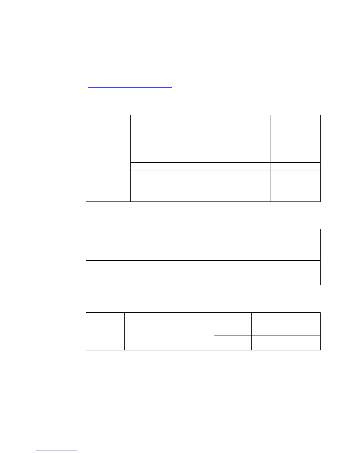
Available protocols per port
The following list provides you with an overview of the open ports on this device.
The table includes the following columns:
●
Protocol
All protocols that the device supports
●
Port number
Port number assigned to the protocol
●
Port status
– Open
The port is always open and cannot be closed.
– Open (when configured)
The port is open if it has been configured.

Security recommendations
SCALANCE W778-1 /W738-1
10 Operating Instructions, 01/2107, C79000-G8976-C450-01
●
Factory setting
– Open
The factory setting of the port is "Open".
– Closed
The factory setting of the port is "Closed".
●
Authentication
Specifies whether or not the protocol is authenticated.
Protocol
Port number
Port status
Factory setting of
the port
Authentication
SSH
TCP/22 Open
(when configured)
Open Yes
TELNET
TCP/23 Open
(when configured)
Open Yes
HTTP
TCP/80 Open
(when configured)
Open Yes
HTTPS
TCP/443 Open
(when configured)
Open Yes
SNTP
NTP
UDP/123 Open
(when configured)
Closed No
SNMP
UDP/161 Open
(when configured)
Open Yes
PROFINET
UDP/34964,
UDP/49154,
49155
Open Open No
Syslog
UDP/514 Open
(when configured)
Open No
EtherNet/IP
TCP/44818,
UDP/2222,44818
Open
(when configured)
Open No
DHCP
UDP/67,68 Open
(when configured)
Closed No
RADIUS
UDP/1812,1813 Open
(when configured)
Closed No
TFTP
UDP/69 Open
(when configured)
Closed No
.
SCALANCE W778-1 /W738-1
Operating Instructions, 01/2107, C79000-G8976-C450-01
11
3
3.1
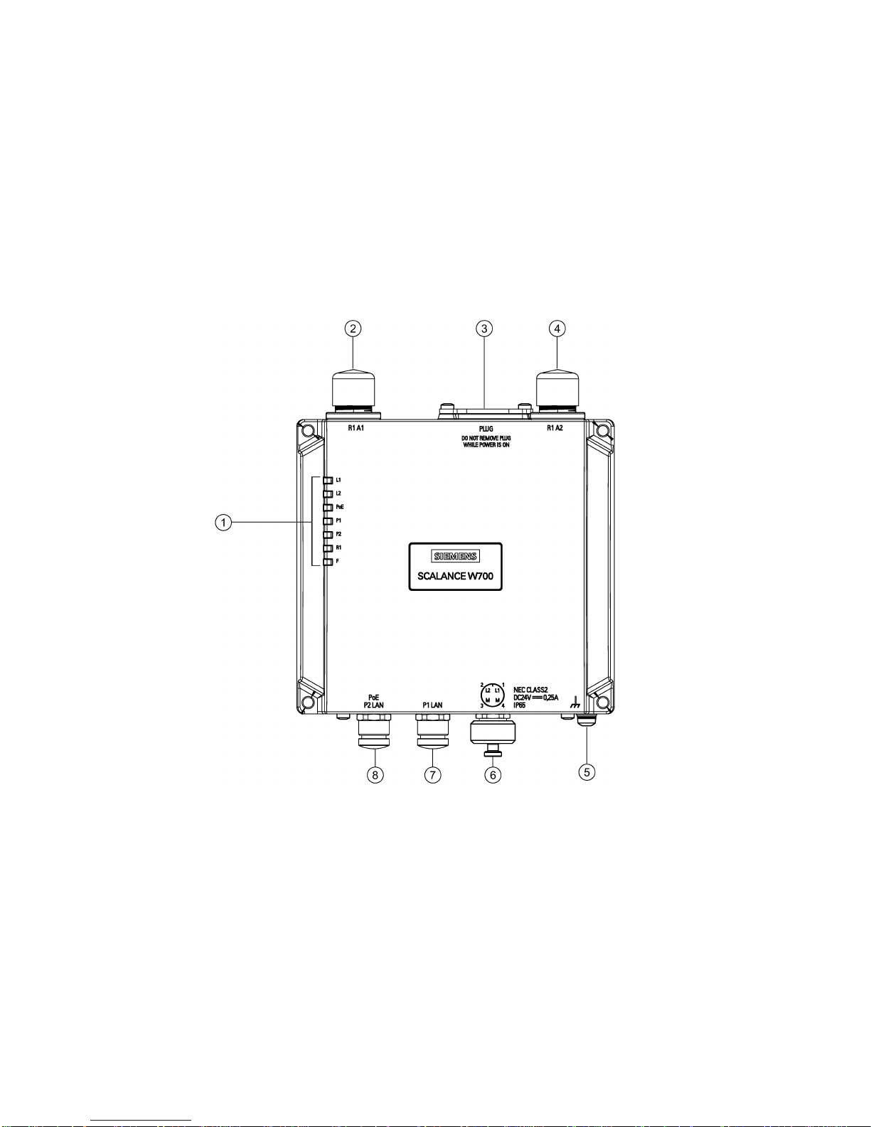
Description of the device
W774-1 /W734-1 M12
①
LED display
②
Antenna connector R1A1
③
PLUG slot / RESET button
④
Antenna connector R1A2
⑤
Grounding
⑥
Connector for power supply (L1, L2)
⑦
Ethernet connector P1
⑧
Ethernet connector P2 (PoE capability)
Description of the device
3.1 Description of the device
SCALANCE W778-1 /W738-1
12 Operating Instructions, 01/2107, C79000-G8976-C450-01
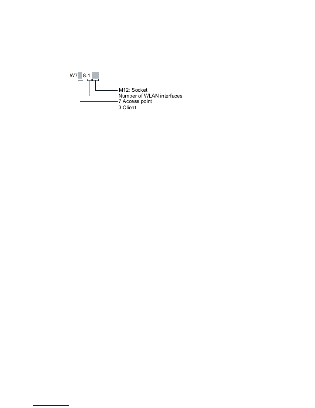
Structure of the type designation
The type designation of the device is made up of several parts that have the following
meaning:
Components of the product
The following components are supplied with the product:
● SCALANCE W778 or SCALANCE W738
● 3 protective caps for the M12 sockets
– 2 x Ethernet
– 1 x power supply
● 2 protective caps for the antenna sockets
● SIMATIC NET Industrial Wireless LAN CD
Please check that the consignment you have received is complete. If the consignment is
incomplete, contact your supplier or your local Siemens office.
Note
The mounting adapter and the bracket for installation on a DIN rail does not ship with the
product, see
Accessories (Page 13).
Description of the device
3.2 Accessories
SCALANCE W778-1 /W738-1
Operating Instructions, 01/2107, C79000-G8976-C450-01
13
3.2
Accessories
Technical data subject to change.
You will find further information on the accessories program in the Industry Mall.
(https://mall.industry.siemens.com)
PLUG
Component
Description
Article number
C-PLUG Configuration PLUG,
Exchangeable storage medium (32 MB) for the configura-
tion data
6GK1 900-0AB00
KEY-PLUG features
Enabling of iFeatures and exchangeable storage medium
for storage of configuration data
KEY-PLUG W780 iFeatures AP
6GK5 907-8PA00
KEY-PLUG W740 iFeatures Client 6GK5 907-4PA00
KEY-PLUG
W700 Security
W700 Security
Enabling of “Inter AP Blocking” and exchangeable storage
medium for storage of configuration data
6GK5907-0PA00
Installation
Component
Description
Article number
Mounting
adapter
DIN rail
Adapter for mounting the W778/W38 on a 35 mm DIN rail
according to DIN EN 50 022
6GK5798-8MF0-0AA1
Bracket
support
Bracket support to install the device rotated through 90°
For optimized cabinet installation.
The mounting adapter is included.
6GK5798-8MA0-0AA1
M12 data plug-in connector
Component
Description
Article number
IE FC M12
PLUG PRO
2x2
M12 data plug-in connector for IE FC
TP cables 2x2, IP65/67, D-coded,
axial cable outlet
1 connector
per package
6GK1 901-0DB20-6AA0
8 connectors
per package
6GK1 901-0DB20-6AA8

Description of the device
3.2 Accessories
SCALANCE W778-1 /W738-1
14 Operating Instructions, 01/2107, C79000-G8976-C450-01
Data line
Component
Description
Article number
IE FC TP STANDARD
CABLE GP2X2
(PROFINET type A)
Standard bus cable, TP installation cable for connection to FC OUTLET RJ-45, for universal use, 4wire, shielded, CAT 5E
Sold by the meter
6XV1 840-2AH10
IE FC TP ROBUST
STANDARD CABLE GP
2X2
(PROFINET type A)
Standard bus cable, ATPE outer jacket for connection to FC RJ-45 PLUG and FC OUTLET RJ45, fixed installation, for universal use, 4-wire,
shielded, CAT 5
Sold by the meter
6XV1 841-2A
IE FC TP ROBUST
FLEXIBLE CABLE GP
2X2
(PROFINET type B)
Flexible bus cable, TPE outer jacket for connection to FC RJ-45 PLUG and FC OUTLET RJ-45,
flexible wires, 4-wire, shielded, CAT 5
Sold by the meter
6XV1 841-2B
IE FC TP FLEXIBLE
CABLE GP 2X2
(PROFINET type B)
Flexible bus cable, TP installation cable, flexible
wires, shielded, CAT 5
Sold by the meter
6XV1 870-2B
IE FC TP TRAILING
CABLE 2X2
(PROFINET type C)
Highly flexible bus cable, TP installation cable for
connection to FC OUTLET RJ-45, for use in drag
chains, 4-wire, shielded, CAT 5
Sold by the meter
6XV1 840-3AH10
IE TP TORSION CABLE
2X2
(PROFINET type C)
Highly flexible bus cable, TP installation cable for
use in highly flexible applications (torsion), 4-wire
Sold by the meter
6XV1 870-2F
IE CONNECTING CABLE
M12-180/IE RJ45
Flexible IE connecting cable, 4-wire, preassembled with a 4-pin M12 plug (D-coded) and an IE
FC RJ-45 plug 145
6XV1 871-5T*
IE CONNECTING CABLE
M12-180/M12-180
Flexible IE connecting cable, 4-wire, preassem-
bled with two 4-pin M12 plugs (D-coded)
6XV1 870-8A*
* Available in different lengths
Cabinet feedthrough
Component
Description
Article number
IE M12 PANEL
FEEDTHROUGH
Cabinet feedthrough for conversion from M12 connector technology (D-coded, IP65) to RJ-45 connector technology (IP20)
pack of 5
6GK1 901-0DM20-2AA5
IE M12 PANEL
FEEDTHROUGH
PRO
Cabinet feedthrough for conversion from M12 connector technology (D-coded, IP65) to M12 connector technology (D-coded, IP65)
pack of 5
6GK1 901-0DM30-2AA5
IE M12 PANEL
FEEDTHROUGH
4X2
Cabinet feedthrough for conversion from M12 connector technology (X-coded, IP65/67) to RJ-45
connector technology (X-coded, IP20)
pack of 5
6GK1 901-0DM40-2AA5

Description of the device
3.2 Accessories
SCALANCE W778-1 /W738-1
Operating Instructions, 01/2107, C79000-G8976-C450-01
15
Component
Description
Article number
N-Connect/NConnect female/female Panel
Feedthrough
Panel feedthrough for wall thicknesses up to a maximum of 4.5 mm, two N-Connect female connectors.
6GK5 798-2PP00-2AA6
N-Connect/SMAConnect female/female Panel
Feedthrough
Panel feedthrough for wall thicknesses up to a maximum of 5.5 mm, two N-Connect/SMA female connectors.
6GK5 798-0PT00-2AA6
See also
Safety when connecting up (Page 35)
Energy cable
Component
Description
Article number
Energy cable 2
x 0.75
Energy cable for connection of signaling contact and power
supply 24 VDC, stranded wire 2 x 0.75 mm
2
, capable of trail-
ing, not assembled
Sold by the meter
6XV1 812-8A
Robust Energy
Cable 4 x 0.75
Energy cable for connection of power supply 24 VDC, 4-wire
stranded 4 x 0.75 mm
2
, robust, flexible, not assembled
Sold by the meter
6XV1 801-2A
M12 PLUG-IN
CABLE
Flexible plug-in power cable to connect the power supply 24
VDC, 4-wire, preassembled with a 4-pin M12 plug and an
M12 socket (A-coded)
6XV1 801-5D*
* Available in different lengths
Socket
Component
Description
Article number
IE POWER M12
CABLE CONNECTOR
PRO
Socket for the 24 VDC power supply. 4-pin,
A-coded
pack of 3
6GK1 907-0DC10-6AA3
Lightning protection
Component
Description
Article number
LP798-1N Lighting protector with N/N female/female connector with
gas discharge technology
6GK5798-2LP00-2AA6
LP798-2N Lighting protector with N/N female/female connector with
quarter wave technology
6GK5798-2LP10-2AA6

Description of the device
3.2 Accessories
SCALANCE W778-1 /W738-1
16 Operating Instructions, 01/2107, C79000-G8976-C450-01
Terminating resistor
Component
Description
Article number
TI795-1N Electrical connection
N-Connect, male
6GK5795-1TN00-1AA0
3.2.1
Flexible connecting cables and antennas
3.2.1.1
Flexible connecting cables
N-Connect/R-SMA flexible connecting cable for RJ-45
Flexible connecting cable for connecting an antenna to a SCALANCE W700. Preassembled
with two connectors N male and R-SMA male
Length
Article number
0.3 m
6XV1875-5CE30
1 m
6XV1875-5CH10
2 m
6XV1875-5CH20
5 m
6XV1875-5CH50
10 m
6XV1875-5CN10
For railway applications, the following connecting cable are available:
Length
Article number
1 m
6XV1875-5TH10
2 m
6XV1875-5TH20
5 m
6XV1875-5TH50
Flexible connecting cable N-Connect/N-Connect
Flexible connecting cable for connecting an antenna to a SCALANCE W700 with N-Connect
connectors.
Preassembled with two N male connectors:
Length
Article number
1 m
6XV1875-5AH10
2 m
6XV1875-5AH20
5 m
6XV1875-5AH50
10 m
6XV1875-5AN10

Description of the device
3.2 Accessories
SCALANCE W778-1 /W738-1
Operating Instructions, 01/2107, C79000-G8976-C450-01
17
For railway applications, the following connecting cable are available:
Length
Article number
1 m
6XV1875-5SH10
2 m 6XV1875-5SH20
5 m
6XV1875-5SH50
Flexible connecting cable IWLAN QMA/N-Connect male/female
Adapter cable for connecting a MIMO antenna with QMA connectors with the flexible
connecting cables. Preassembled with two connectors QMA male and N-Connect female.
pack of 3
Length
Article number
1 m 6XV1875-5JH10
For railway applications, the following connecting cable is available Note: Scope of delivery:
Pack of 1
Length
Article number
1 m
6XV1875-5VH10
3.2.1.2
Antennas
Note
When you select an antenna, keep in mind the national approvals for your device.
You will find more information in the following Link (
http://www.siemens.com/wireless-
approvals
)
Type
Properties
Article number
ANT792-4DN RCoax helical antenna, circular
polarization, 4 dBi, 2.4 GHz, N-
Connect female.
6GK5 792-4DN00-0AA6
ANT792-6MN Omni antenna, mast/wall mounting,
6 dBi 2.4 GHz, N-Connect female
6GK5 792-6MN00-0AA6
ANT792-8DN Directional antenna, mast/wall
mounting, 14 dBi 2.4 GHz, N-
Connect female
6GK5 792-8DN00-0AA6
ANT793-4MN RCoax λ5/8 antenna with vertical
polarization, 6 dBi, 5 GHz, N-
Connect female.
6GK5 793-4MN00-0AA6
ANT793-6DG Wide angle antenna, mast/wall
mounting, 9 dBi 5 GHz, 2 x N-
Connect female
6GK5 793-6DG00-0AA0

Description of the device
3.2 Accessories
SCALANCE W778-1 /W738-1
18 Operating Instructions, 01/2107, C79000-G8976-C450-01
Type
Properties
Article number
ANT793-6DT Wide angle antenna (MIMO),
mast/wall mounting, 8 dBi 5 GHz, 3
x QMA connector female
6GK5 793-6DT00-0AA0
ANT793-6MN Omni antenna, mast/wall mounting,
5 dBi 5 GHz, N-Connect female
6GK5 793-6MN00-0AA6
ANT793-8DJ Directional antenna, mast/wall
mounting, 18 dBi 5 GHz, 2 x N-
Connect female
6GK5 793-8DJ00-0AA0
ANT793-8DK Directional antenna, mast/wall
mounting, 23 dBi 5 GHz, 2 x N-
Connect female
6GK5 793-8DK00-0AA0
ANT795-4MA Omni antenna, directly on the de-
vice, 3/5 dBi 2.4 GHz and 5 GHz,
IP30, R-SMA connector male for
direct mounting on the device,
connector angle adjustable 0° to
180°.
6GK5 795-4MA00-0AA3
ANT795-4MC Omnidirectional antenna, 3/5 dBi,
2.4 GHz and 5 GHz, IP65, NConnect male for direct installation
on the device, straight connector.
6GK5 795-4MC00-0AA3
ANT795-4MD Omnidirectional antenna, 3/5 dBi,
2.4 GHz and 5 GHz, IP65, NConnect male for direct installation
on the device, 90° connector.
6GK5 795-4MD00-0AA3
ANT795-6DC Wide angle antenna, mast/wall
mounting, 9 dBi 2.4 GHz and 5
GHz, N-Connect female
6GK5 795-6DC00-0AA0
ANT795-6MN Omni antenna, mounted on
roof/vehicle, 6/8 dBi 2.4 GHz and 5
GHz, N-Connect female
6GK5 795-6MN10-0AA6
ANT795-6MT
Omni antenna (MIMO), mounted on
roof/vehicle/ceiling, 5/7 dBi 2.4
GHz and 5 GHz, 3 x QMA con-
nector female
6GK5 795-6MT00-0AA0
ANT793-8DL Directional antenna vertical-
horizontal polarized, 5 GHz, 14dBi,
IP66, 2xN-Connect female
6GK5 793-8DL00-0AA0
ANT793-8DP Directional antenna, mast/wall
mounting, 13 / 13.5 dBi 4.9 GHz
and 5 GHz, N-Connect female
6GK5 793-8DP00-0AA0
ANT795-4MX Omnidirectional antenna, 2/2,5 dBi,
2.4 GHz and 5 GHz, IP69K, N-
Connect male
6GK5 795-4MX00-0AA0
ANT795-6MP Omnidirectional antenna, 5/7 dBi,
2.4 GHz and 5 GHz, IP65/67, N-
Connect female
6GK5 795-6MP00-0AA0
 Loading...