

Page 1

RVD240
District Heating and Domestic Hot Water Controller
Basic Documentation
Edition 3.0
Controller series D
CE1P2384en
27.05.2004
Siemens Building Technologies
HVAC Products
Page 2

Siemens Building Technologies AG
HVAC Products
Gubelstrasse 22
CH 6301 Zug
Tel. +41 41 724 24 24
Fax +41 41 724 35 22
www.landisstaefa.com
2/126
Siemens Building Technologies Basic documentation RVD240 CE1P2384en
HVAC Products 27.05.2004
© 1999 Siemens Building Technologies AG
Subject to change
Page 3

Contents
1 Summary ....................................................................................................... 13
1.1 Brief description and key features ................................................................. 13
1.2 Type summary............................................................................................... 13
1.3 Equipment combinations ............................................................................... 13
1.3.1 Suitable sensors ............................................................................................ 13
1.3.2 Suitable room units........................................................................................ 14
1.3.3 Suitable valve actuators ................................................................................14
1.3.4 Communication.............................................................................................. 14
1.3.5 Documentation ..............................................................................................14
2 Use ................................................................................................................ 15
2.1 Types of plant ................................................................................................ 15
2.2 Types of houses and buildings ...................................................................... 15
2.3 Types of heating systems.............................................................................. 15
2.4 Heating circuit functions ................................................................................15
2.5 D.h.w. functions ............................................................................................. 16
2.6 Auxiliary functions.......................................................................................... 16
3 Fundamentals................................................................................................ 18
3.1 Key technical features ................................................................................... 18
3.1.1 Function blocks.............................................................................................. 18
3.1.2 Plant types..................................................................................................... 18
3.2 Operating modes ........................................................................................... 22
3.2.1 Heating circuit control .................................................................................... 22
3.2.2 D.h.w. heating................................................................................................ 23
3.2.3 Manual operation........................................................................................... 23
4 Acquisition of measured values..................................................................... 24
4.1 General.......................................................................................................... 24
4.2 Flow temperature heating circuit ...................................................................24
4.2.1 Types of sensors ........................................................................................... 24
4.2.2 Handling faults............................................................................................... 24
4.3 Outside temperature (B9) .............................................................................. 24
4.3.1 Types of sensors ........................................................................................... 24
4.3.2 Handling faults............................................................................................... 24
4.4 Room temperature (A6)................................................................................. 25
4.4.1 Types of sensors ........................................................................................... 25
4.4.2 Handling faults............................................................................................... 25
4.4.3 Room model .................................................................................................. 25
4.5 D.h.w. temperature (B3) ................................................................................ 25
4.5.1 Measured variable ......................................................................................... 25
3/126
Siemens Building Technologies Basic documentation RVD240 CE1P2384en
HVAC Products Contents 27.05.2004
Page 4

4.5.2 Types of sensors............................................................................................25
4.5.3 Handling faults ...............................................................................................26
4.6 D.h.w. storage tank temperature (B31)..........................................................26
4.6.1 Measured variable .........................................................................................26
4.6.2 Types of sensors............................................................................................26
4.6.3 Handling faults ...............................................................................................26
4.7 D.h.w. storage tank or return temperature (B32) ...........................................26
4.7.1 Measured variable .........................................................................................26
4.7.2 Types of sensors............................................................................................26
4.7.3 Handling faults ...............................................................................................27
4.8 Return temperature (B7, B71 and B72) .........................................................27
4.8.1 Measurement .................................................................................................27
4.8.2 Types of sensors............................................................................................27
4.8.3 Handling faults ...............................................................................................27
5 Function block Space heating........................................................................28
5.1 Operating lines...............................................................................................28
5.2 Settings and displays .....................................................................................28
5.3 Heating program ............................................................................................29
6 Function block Clock settings ........................................................................30
6.1 Operating lines...............................................................................................30
6.2 Entries............................................................................................................30
7 Function block End-user d.h.w.......................................................................31
7.1 Operating lines...............................................................................................31
7.2 D.h.w. heating program..................................................................................31
7.3 Adjustment of setpoints..................................................................................31
8 Function block Display of actual sensor values .............................................32
8.1 Operating lines...............................................................................................32
8.2 Displays .........................................................................................................32
9 Function block Holiday settings .....................................................................33
9.1 Operating lines...............................................................................................33
9.2 Holiday program.............................................................................................33
10 Function block Indication of errors .................................................................34
10.1 Operating line.................................................................................................34
10.2 Indication of errors .........................................................................................34
11 Function block Plant configuration .................................................................35
11.1 Operating lines...............................................................................................35
11.2 Parameters to be set......................................................................................35
11.2.1 Plant type .......................................................................................................35
11.2.2 Input B71 / U1 ................................................................................................35
4/126
Siemens Building Technologies Basic documentation RVD240 CE1P2384en
HVAC Products Contents 27.05.2004
Page 5

11.2.3 Circulating pump............................................................................................ 36
11.2.4 Input H5 ......................................................................................................... 36
11.2.5 Control of variable speed pump..................................................................... 36
12 Function block Space heating .......................................................................40
12.1 Operating lines ..............................................................................................40
12.2 Compensating variables ................................................................................40
12.2.1 Outside temperature...................................................................................... 40
12.2.2 Room temperature......................................................................................... 41
12.3 Heating curve ................................................................................................42
12.4 Generation of setpoint ...................................................................................43
12.4.1 Display of setpoint ......................................................................................... 43
12.4.2 Setpoint of weather-compensated control ..................................................... 43
12.4.3 Setpoint of room-compensated control.......................................................... 44
12.4.4 Setpoint of weather-compensated control with room influence ..................... 44
12.5 Heating circuit control ....................................................................................45
12.5.1 Weather-compensated control ......................................................................45
12.5.2 Room-compensated control ..........................................................................45
12.5.3 Weather-compensated control with room influence ......................................45
12.6 Automatic ECO function ................................................................................46
12.6.1 Fundamentals................................................................................................ 46
12.6.2 Compensating variables and auxiliary variables ...........................................46
12.6.3 Heating limit................................................................................................... 47
12.6.4 Mode of operation of ECO function 1 ............................................................ 47
12.6.5 Mode of operation of ECO function 2 ............................................................ 47
12.7 Pump overrun ................................................................................................47
12.8 Maximum limitation of the room temperature ................................................47
12.9 Optimization................................................................................................... 48
12.9.1 Definition and purpose................................................................................... 48
12.9.2 Fundamentals................................................................................................ 48
12.9.3 Process.......................................................................................................... 49
12.9.4 Room model temperature.............................................................................. 49
12.9.5 Optimum stop control ....................................................................................50
12.9.6 Quick setback ................................................................................................ 50
12.9.7 Optimum start control .................................................................................... 50
12.9.8 Maximum rate of flow temperature increase .................................................51
12.10 Frost protection for the building ..................................................................... 51
12.10.1 General.......................................................................................................... 51
12.10.2 Mode of operation with room sensor ............................................................. 51
12.10.3 Mode of operation without room sensor ........................................................ 51
12.11 Protective functions ....................................................................................... 52
12.11.1 Pump kick ...................................................................................................... 52
12.11.2 Valve kick ......................................................................................................52
5/126
Siemens Building Technologies Basic documentation RVD240 CE1P2384en
HVAC Products Contents 27.05.2004
Page 6

12.11.3 Shutdown of pump .........................................................................................52
12.11.4 Pump and mixing valve overrun.....................................................................52
13 Function block Valve actuator of heat converter............................................54
13.1 Operating lines...............................................................................................54
13.2 Mode of operation ..........................................................................................54
13.3 Control process..............................................................................................54
13.4 Maximum limitation of the flow temperature ..................................................54
13.5 Minimum limitation of the flow temperature ...................................................54
13.6 External heat demand at input H5 .................................................................55
13.7 External heat demand at input U1 .................................................................55
14 Function block Valve actuator heating circuit..................................................56
14.1 Operating lines...............................................................................................56
14.2 Mode of operation ..........................................................................................56
14.3 Control process..............................................................................................56
14.4 Maximum limitation of the flow temperature ..................................................56
14.5 Minimum limitation of the flow temperature ...................................................57
15 Function block D.h.w. heating........................................................................58
15.1 Operating lines...............................................................................................58
15.2 Release of d.h.w. heating ..............................................................................58
15.3 Control of the circulating pump ......................................................................59
15.4 Switching differential of d.h.w. control............................................................59
15.5 Legionella function .........................................................................................59
15.6 Priority of d.h.w. heating ................................................................................59
15.6.1 General ..........................................................................................................59
15.6.2 Absolute priority .............................................................................................60
15.6.3 Shifting priority ...............................................................................................60
15.6.4 No priority.......................................................................................................61
15.7 Pump overrun ................................................................................................61
15.7.1 General ..........................................................................................................61
15.7.2 Intermediate circuit pump...............................................................................61
15.7.3 Storage tank charging pump..........................................................................61
15.8 Frost protection for d.h.w. ..............................................................................62
15.9 Switching d.h.w. heating off ...........................................................................62
16 D.h.w. heating ................................................................................................63
16.1 D.h.w. heating with storage tanks ..................................................................63
16.1.1 General ..........................................................................................................63
16.1.2 Maximum charging time.................................................................................63
16.1.3 Manual storage tank heating..........................................................................63
16.1.4 Forced charging .............................................................................................63
16.1.5 Protection against discharging.......................................................................64
16.1.6 Protection against overtemperatures .............................................................64
6/126
Siemens Building Technologies Basic documentation RVD240 CE1P2384en
HVAC Products Contents 27.05.2004
Page 7

16.1.7 Storage tank with electric immersion heater.................................................. 64
16.2 D.h.w. heating with stratification storage tank ...............................................64
16.2.1 General.......................................................................................................... 64
16.2.2 D.h.w. heating................................................................................................ 65
16.2.3 Feeding the circulating water into the heat exchanger .................................. 65
16.3 Direct d.h.w. heating...................................................................................... 65
16.3.1 General.......................................................................................................... 65
16.3.2 D.h.w. heating................................................................................................ 65
16.3.3 Protection against cooling down.................................................................... 66
16.3.4 Siting the sensors .......................................................................................... 66
16.3.5 Flow switch .................................................................................................... 67
16.3.6 Compensation of heat losses through control ............................................... 67
16.3.7 Cold water sensor.......................................................................................... 68
17 Function block Extra legionella functions ......................................................69
17.1 Operating lines ..............................................................................................69
17.1.1 Legionella function......................................................................................... 69
17.1.2 Setpoint .........................................................................................................69
17.1.3 Time............................................................................................................... 69
17.1.4 Dwelling time ................................................................................................. 69
17.1.5 Operation of circulating pump........................................................................ 70
17.1.6 Maximum limitation of the return temperature ............................................... 70
17.2 Mode of operation.......................................................................................... 70
18 Function block Valve actuator d.h.w.............................................................. 72
18.1 Operating lines ..............................................................................................72
18.2 Mode of operation.......................................................................................... 72
18.3 Control process .............................................................................................72
18.4 Setpoint boost................................................................................................ 72
18.4.1 Charging boost .............................................................................................. 73
18.4.2 Flow temperature boost................................................................................. 73
18.5 Maximum setpoint of the d.h.w. temperature ................................................73
18.6 D.h.w. charging with two storage tank sensors .............................................73
18.7 Adjustable load limit....................................................................................... 73
18.7.1 Adjustment to the time of year....................................................................... 73
18.7.2 Load limit ....................................................................................................... 74
18.7.3 Child-proofing ................................................................................................ 74
19 Function block Assignment of d.h.w. ............................................................. 75
19.1 Operating line ................................................................................................75
19.2 Assignment of d.h.w. heating ........................................................................ 75
20 Function block LPB parameters ....................................................................76
20.1 Operating lines ..............................................................................................76
20.2 LPB parameters............................................................................................. 76
7/126
Siemens Building Technologies Basic documentation RVD240 CE1P2384en
HVAC Products Contents 27.05.2004
Page 8

20.2.1 Addressing the devices..................................................................................76
20.2.2 Source of time of day .....................................................................................76
20.2.3 Bus power supply...........................................................................................77
20.2.4 Outside temperature source ..........................................................................77
21 Locking signals ..............................................................................................78
21.1 Fundamentals ................................................................................................78
21.2 Critical locking signals....................................................................................78
21.3 Uncritical locking signals................................................................................78
21.3.1 General ..........................................................................................................78
21.3.2 Controller-internal uncritical locking signals...................................................79
21.3.3 Uncritical locking signals from the data bus...................................................79
22 Function block Device functions ....................................................................80
22.1 Operating lines...............................................................................................80
22.2 Actuator pulse lock.........................................................................................80
22.3 Frost protection for the plant ..........................................................................80
22.3.1 Principle .........................................................................................................80
22.3.2 Mode of operation with outside sensor ..........................................................80
22.3.3 Mode of operation without outside sensor .....................................................81
22.3.4 Frost protection for the heating circuit flow ....................................................81
22.4 Flow alarm .....................................................................................................81
22.4.1 Heating circuit and d.h.w. circuit with storage tanks ......................................81
22.4.2 Direct d.h.w. heating via heat exchanger.......................................................82
22.5 Winter- / summertime changeover.................................................................83
23 Function block M-bus parameter ...................................................................84
23.1 Operating lines...............................................................................................84
23.2 General ..........................................................................................................84
23.3 Addressing and identification .........................................................................84
23.4 Baud rate .......................................................................................................84
23.5 Load management .........................................................................................84
23.5.1 Load management of d.h.w. ..........................................................................84
23.5.2 Load management of the heating system......................................................84
23.5.3 Resetting the load control signals ..................................................................85
23.5.4 Use on the LPB..............................................................................................85
23.5.5 Resolution of M-bus signals...........................................................................85
24 Function block PPS parameter ......................................................................86
24.1 Operating lines...............................................................................................86
24.2 Suitable devices.............................................................................................86
24.3 Impacts of a room unit on the heating circuits ...............................................86
25 Function block Test and display.....................................................................87
25.1 Operating lines...............................................................................................87
8/126
Siemens Building Technologies Basic documentation RVD240 CE1P2384en
HVAC Products Contents 27.05.2004
Page 9

25.2 Sensor test ....................................................................................................87
25.3 Setpoint test................................................................................................... 87
25.4 Relay test....................................................................................................... 88
25.5 Display of the pump speed ............................................................................88
25.6 Display of the digital inputs............................................................................ 88
25.7 Limitations .....................................................................................................89
25.8 Software version............................................................................................ 90
26 Function block DRT and maximum limitation of the return temperature .......91
26.1 Operating lines ..............................................................................................91
26.2 Maximum limitation of the primary return temperature ..................................91
26.2.1 General.......................................................................................................... 91
26.2.2 Maximum limitation in heating mode ............................................................. 92
26.2.3 Maximum limitation in d.h.w. mode ...............................................................92
26.3 Maximum limitation of the secondary return temperature .............................93
26.4 Maximum limitation of the temperature differential (DRT function) ............... 94
26.4.1 Mode of operation.......................................................................................... 94
26.4.2 Purpose ......................................................................................................... 94
26.5 Integral action time of the limitation functions................................................ 94
27 Function block Various functions................................................................... 95
27.1 Operating lines ..............................................................................................95
27.2 Limitation function at contact H5 ................................................................... 95
27.3 Suppression of hydraulic creep .....................................................................96
27.3.1 Mode of operation.......................................................................................... 96
27.3.2 Mode of operation.......................................................................................... 96
27.4 Raising the reduced room temperature setpoint ...........................................96
28 Function block Operation locking functions ................................................... 98
28.1 Operating lines ..............................................................................................98
28.2 Locking settings on the software side............................................................ 98
28.3 Locking of setting level "Locking functions" on the hardware side ................98
29 Combination with PPS devices...................................................................... 99
29.1 General.......................................................................................................... 99
29.2 Combination with room unit QAW50... .......................................................... 99
29.2.1 General.......................................................................................................... 99
29.2.2 Overriding the operating mode ...................................................................... 99
29.2.3 Knob for room temperature readjustments.................................................. 100
29.2.4 Controller with operation lock ......................................................................100
29.3 Combination with room unit QAW70 ........................................................... 100
29.3.1 General........................................................................................................ 100
29.3.2 Overriding the operating mode .................................................................... 101
29.3.3 Knob for readjusting the room temperature................................................. 101
29.3.4 Impact of the individual QAW70 operating lines on the RVD240 ................101
9/126
Siemens Building Technologies Basic documentation RVD240 CE1P2384en
HVAC Products Contents 27.05.2004
Page 10

29.3.5 Controller with operation lock.......................................................................102
29.3.6 Entry of holiday periods ...............................................................................102
29.4 Room temperature sensor QAA10...............................................................102
30 Manual operation .........................................................................................103
31 Handling.......................................................................................................104
31.1 Operation .....................................................................................................104
31.1.1 General ........................................................................................................104
31.1.2 Analog operating elements ..........................................................................105
31.1.3 Digital operating elements ...........................................................................105
31.1.4 Controller in "nonoperated state" .................................................................106
31.1.5 Safety concept .............................................................................................106
31.1.6 Setting levels and access rights...................................................................106
31.2 Commissioning ............................................................................................107
31.2.1 Installation instructions.................................................................................107
31.2.2 Operating lines.............................................................................................107
31.3 Installation....................................................................................................107
31.3.1 Mounting location.........................................................................................107
31.3.2 Mounting choices .........................................................................................107
31.3.3 Electrical installation ....................................................................................108
32 Engineering..................................................................................................109
32.1 Connection terminals ...................................................................................109
32.2 Relays ..........................................................................................................110
32.3 PWM output .................................................................................................110
32.4 Lightning protection in M-bus plants ............................................................110
32.5 Connection diagrams ...................................................................................111
32.5.1 Low-voltage side ..........................................................................................111
32.5.2 Mains voltage side .......................................................................................111
33 Mechanical design .......................................................................................112
33.1 Basic design.................................................................................................112
33.2 Dimensions ..................................................................................................112
34 Technical data..............................................................................................113
10/126
Siemens Building Technologies Basic documentation RVD240 CE1P2384en
HVAC Products Contents 27.05.2004
Page 11
Heat source, heat
generation
Pumps
D.h.w. heating
Glossary
In this Basic Documentation, the following key terms are used:
Term Explanation
Heat converter Heat exchanger that, on the primary side, is con-
nected to the district heat network and that, on the
secondary side, delivers the hot water to a common flow. The flow then supplies the hot water to
several consumers that are controlled by zone
controllers, etc.
Heat exchanger Heat exchanger that delivers the heat directly to
the consumers (e.g. space heating, d.h.w. heating, etc.).
Term Explanation
Storage tank charging pump Pump that supplies tap water via the heat ex-
changer into the storage tank where it is made
available as d.h.w.
Intermediate circuit pump Pump that supplies water as a heat carrier. The
water transfers its heat via a coil or storage tank
to the d.h.w. without getting in direct contact with
it.
Term Explanation
Coil type storage tank
2383S3 3
Instantaneous d.h.w. heating (via
heat exchanger)
2383S3 4
Stratification storage tank
2383S3 5
Storage tanks Common term used for coil type and stratification
storage tanks.
11/126
Siemens Building Technologies Basic documentation RVD240 CE1P2384en
HVAC Products Glossary 27.05.2004
Page 12

12/126
Siemens Building Technologies Basic documentation RVD240 CE1P2384en
HVAC Products Glossary 27.05.2004
Page 13

1 Summary
1.1 Brief description and key features
• The RVD240 is a multifunctional heating controller for controlling the flow tempera-
ture of 2 heating circuits and for controlling d.h.w. heating
• The controller’s field of use covers exclusively plants with district heat connections. It
has been designed specifically for small to medium-size residential and nonresidential buildings with 2 heating circuits
• The RVD240 has 4 heating circuit types and 11 d.h.w. plant types preprogrammed.
By combining the different plants, it is possible to configure 14 plant types. The configuration activates all functions and settings required for the respective type of plant
• In terms of control, the RVD240 is designed as a flow temperature controller. Control
can be effected in one of 5 different ways:
− Only weather-compensated control of the heating circuit flow temperatures
− Weather- and room-compensated control of the heating circuit flow temperatures
− Only room-compensated control of the heating circuit flow temperatures
− Demand-dependent control of the common heating circuit flow temperature
• In terms of d.h.w. control, the RVD240 is designed for the following types of applica-
tions:
− D.h.w. heating with coil type storage tanks
− D.h.w. heating with stratification storage tanks
− Direct d.h.w. heating via heat exchanger
− Common or separate heat exchangers for the heating circuit and d.h.w. heating
− Two-stage separation of the d.h.w. from district heating
• The RVD240 is suited for the control of 2-port and 3-port valves and pumps, includ-
ing variable speed pumps
• For the direct adjustment of the nominal room temperature setpoint, there is a setting
knob available. All the other parameters are set digitally based on the operating line
principle
• Key design features: Operating voltage AC 230 V, CE conformity, overall dimensions
to DIN 43700 (96 × 144 mm)
1.2 Type summary
The RVD240 is a compact controller and requires no accessories such as inserts, plugin modules, etc. The controller is supplied complete with base.
1.3 Equipment combinations
1.3.1 Suitable sensors
• For the flow temperatures:
Suitable are all types of temperature sensors that use a sensing element LGNi 1000. The following types are presently available:
− Strap-on temperature sensor QAD22
− Immersion temperature sensors QAE2...
For the control of the d.h.w. flow temperature (B3), it is also possible to use commercially available sensors with Pt 500 sensing elements
• For the return temperatures:
The following types of temperature sensors are presently available:
− Strap-on temperature sensor QAD22
− Immersion temperature sensors QAE2...
13/126
Siemens Building Technologies Basic documentation RVD240 CE1P2384en
HVAC Products 1 Summary 27.05.2004
Page 14

For the control of the primary return temperatures (B7, B71, B72), it is also possible to
use commercially available sensors with Pt 500 sensing elements.
• For the outside temperature:
− Outside sensor QAC22 (sensing element LG-Ni 1000)
− Outside sensor QAC32 (sensing element NTC 575)
• For the room temperature:
PPS-compatible sensors must be used. The following units are available:
− Room temperature sensor QAA10
• For the storage tank temperature:
− Cable temperature sensor QAP21.3
− Immersion temperature sensors QAE2...
1.3.2 Suitable room units
• Room units QAW50...
• Room unit QAW70
1.3.3 Suitable valve actuators
All actuators from Siemens with the following features can be used:
• Electric or electrohydraulic actuators with a running time of 10...900 seconds
• 3-position control
• Operating voltage AC 24 V...AC 230 V
1.3.4 Communication
Communication with other devices, controllers, etc., is possible:
• Via LPB, e.g. assignment of d.h.w., reception of radio signal, master / slave assign-
ments for the time switch, reception of outside temperature signal
• Via M-bus, e.g. reading setpoints and actual values, or output control for space heat-
ing
1.3.5 Documentation
Type of documentation Classification number
Data Sheet RVD240 N2384
Operating Instructions RVD240 B2384
Installation Instructions RVD240 G2384
Data Sheet QAW50... N1635
Data Sheet QAW70 N1637
Installation Instructions QAW70 G1637
Data Sheet QAA10 N1725
Data Sheet "LPB Basic System Data" N2030
Data Sheet "LPB Basic Engineering Data" N2032
Basic Documentation M-Bus P5361
14/126
Siemens Building Technologies Basic documentation RVD240 CE1P2384en
HVAC Products 1 Summary 27.05.2004
Page 15

2 Use
2.1 Types of plant
Basically, the RVD240 is suited for the control of all types of heating plants in houses or
buildings
• that are connected to a district heat network
• that use 2 heating circuits
• in which the flow temperature of the heating circuits is controlled either weather- or
room-compensated
• in which the control of d.h.w. heating can be integrated as an option
2.2 Types of houses and buildings
Basically, the RVD240 is suited for use in all types of houses and buildings in which the
heating is controlled either weather- or room-compensated. It has been designed especially for:
• Single-family homes
• Multifamily houses
• Small to medium-size non-residential buildings
2.3 Types of heating systems
The RVD240 is suited for use with all standard heating systems, such as:
• Radiators
• Convectors
• Underfloor heating systems
• Ceiling heating systems
• Radiant panels
2.4 Heating circuit functions
The RVD240 is used if 1 or several of the following heating circuit functions is / are
required:
• Weather- or room-compensated or weather- and room-compensated flow tempera-
ture control
• Separate flow temperature control of both heating circuits
• Flow temperature control through a modulating seat or slipper valve
• Common or separate heat exchangers for the heating circuits and for d.h.w. heating
• Optimum heating up and setback of the room temperature by learning the switch-on
and switch-off time
• Quick setback with and without room temperature sensor
• ECO function: Demand-dependent switching of the heating system as a function of
the outside temperature
• 7-day program for the heating periods with a maximum of 3 heating periods per day
and varying on times
• Frost protection for the plant and the house or building
• Yearly clock
• Holiday programs
• Independent time programs for space heating and d.h.w.
• Separate time programs for each heating circuit
15/126
Siemens Building Technologies Basic documentation RVD240 CE1P2384en
HVAC Products 2 Use 27.05.2004
Page 16

• Maximum rate of flow temperature increase
• Minimum and maximum limitation of the flow temperature
• Maximum limitation of the room temperature
• Flow alarm
• Heat demand signal can be received
• Differential temperature limitation (DRT function)
• Maximum limitation of the primary return temperature, can be adjusted with 4 vari-
ables
• Limitation of power or volumetric flow by pulses
• Suppression of hydraulic creep in the primary circuit
• Weather-compensated raising of the reduced room temperature setpoint
• Remote operation via room unit
2.5 D.h.w. functions
The RVD240 is used if one or several of the following d.h.w. functions is / are required:
• Common or separate heat exchangers for the heating circuit and for d.h.w. heating
• D.h.w. heating with a coil type storage tank, with charging pump
• Direct d.h.w. heating via heat exchanger
• D.h.w. heating with coil type or stratification storage tanks, with or without mixing
valve in the intermediate circuit
• Continuous d.h.w. heating with mixing valve
• Flow switch with an adjustable load limit, child-proofing and adaptation to the season
• Own time program for the release of d.h.w.
• Optional assignment of the circulating pump to the heating circuit or the d.h.w. circuit
time program
• Protection against cooling down with d.h.w. heating via heat exchanger
• Legionella protection
• Forced d.h.w. charging
• frost protection for d.h.w.
• Selectable priority for d.h.w. heating : Absolute, shifting or parallel
• Manual d.h.w. charging outside the time program
• Maximum limitation of the d.h.w. return temperature
• Flow alarm
2.6 Auxiliary functions
The RVD240 is used if one or several of the following functions is / are required:
• Pump kick, periodic pump run
• Demand-dependent control of the common flow
• Pump overrun
• Valve kick, periodic activation of all actuators on the secondary side
• PWM output, control of a variable speed pump
• Display of parameters, actual values, operating states and fault status signals
• Alarm input
• Analog input DC 0...10 V (display, external heat demand)
• Digital input (heat meter, external heat demand, etc.)
• Flow switch (including child-proofing and adaptation to the season)
• Communication via M-bus
• Communication via LPB (Local Process Bus)
• Service functions
• Pulse lock for actuators
• Sensor test
16/126
Siemens Building Technologies Basic documentation RVD240 CE1P2384en
HVAC Products 2 Use 27.05.2004
Page 17

• Relay test
• Display of setpoint
• Display of all active limitations
• Locking of settings
• Connection of sensors for display only
17/126
Siemens Building Technologies Basic documentation RVD240 CE1P2384en
HVAC Products 2 Use 27.05.2004
Page 18

3 Fundamentals
3.1 Key technical features
The RVD240 offers 2 key technical features:
• The controller has 14 different plant types preprogrammed.
Subsection 3.1.2 shows the relevant plant diagrams.
• The settings are assigned to different setting levels each of which contains a number
of function blocks with the relevant settings
3.1.1 Function blocks
Setting levels Function block
End-user
Heating engineer
Locking functions
Space heating
Clock setting
End-user d.h.w. heating
Display of actual sensor values
Holiday settings
Indication of errors
Plant configuration
Space heating
Actuator heat exchanger
Actuator heating circuit
D.h.w. heating
D.h.w. actuator
Assignment of d.h.w.
Extra legionella functions
LPB parameter
Control functions
M-bus parameter
PPS parameter
Test and display
DRT and limitation of the return temperature
Various functions
Locking functions
For each function block, the required settings are available in the form of operating
lines. On the following pages, a description of the individual functions per block and
line is given.
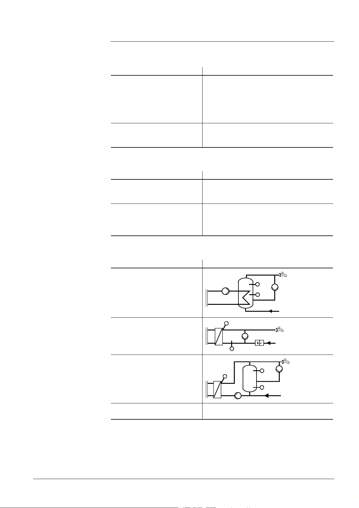
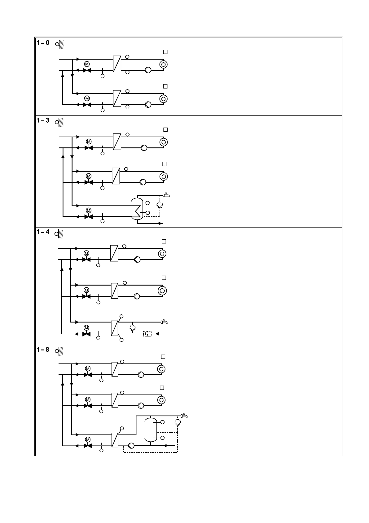
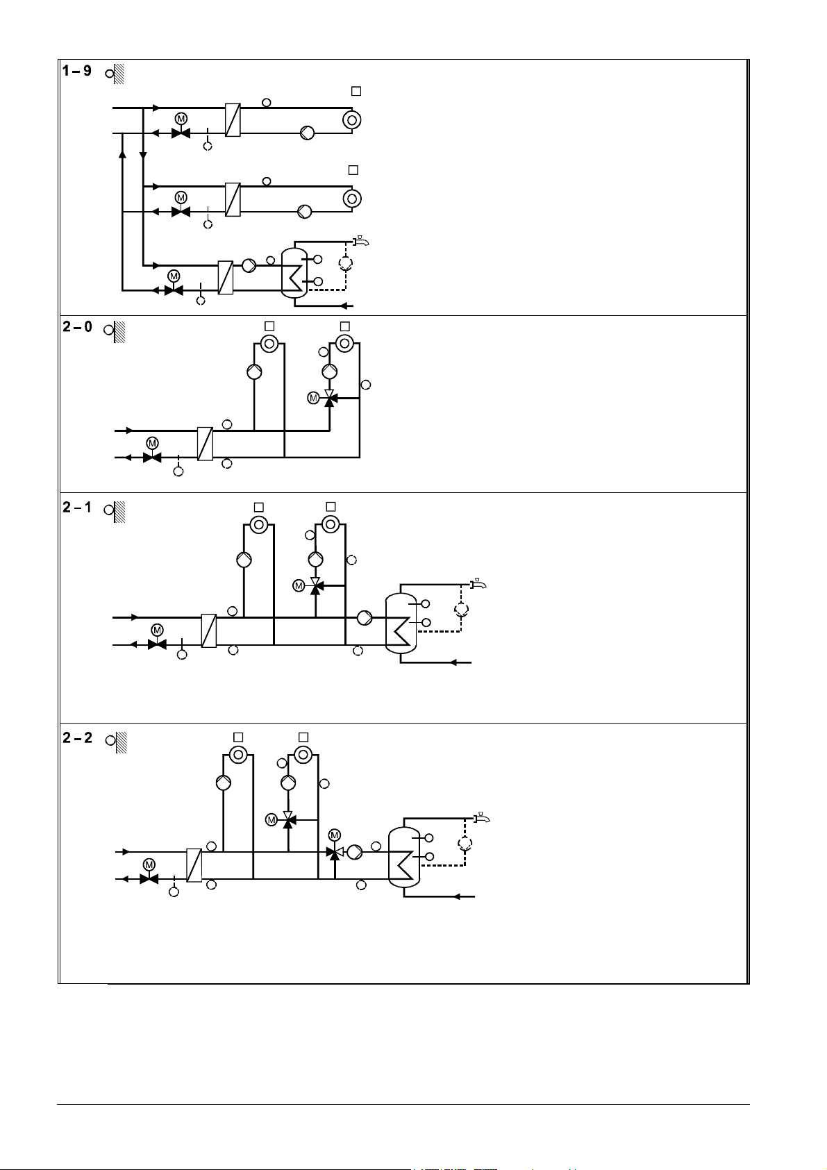
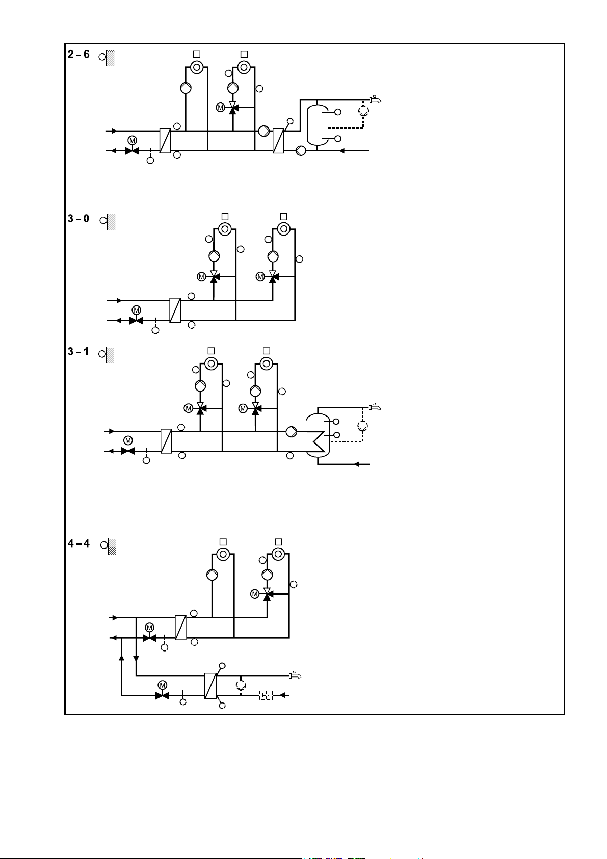
3.1.2 Plant types
The RVD240 has 14 plant types preprogrammed; the functions required for each type
of plant are ready assigned. When commissioning the installation, the relevant plant
type must be selected.
Each plant type is comprised of 2 heating circuits and 1 d.h.w. circuit. When making
use of all possible or practical combinations, the above mentioned total of 14 plant
types are available.
With the number of preprogrammed plant types available, practically all types of heating plants with district heat connection and own d.h.w. heating can be handled and
controlled.
Note on the plant
diagrams
18/126
Siemens Building Technologies Basic documentation RVD240 CE1P2384en
HVAC Products 3 Fundamentals 27.05.2004
Elements shown in broken lines (sensors B7 and B71, circulating pump and flow
switch) are optional components.
Page 19
Type ref. Diagram Legend
B9
Y1
Y7 B72
B9 A6
Y1
Y7 B72
B1
B7 B71
B12
B3
B1
B7
B12
Q1
Q2
Q1
Q2
B31
B32
A6
A6
A6
Q3
A6 Room units
B1 Flow sensor heating circuit 1
B12 Flow sensor heating circuit 2
B3 Secondary return sensor heating circuit 2
B7 Primary return sensor heating circuit 1*
B71 Secondary return sensor heating circuit 1
B72 Primary return sensor heating circuit 2*
B9 Outside sensor
Q1 Pump heating circuit 1
Q2 Pump heating circuit 2
Y1 2-port valve primary return heating circuit 2
2384S01
Y7 2-port valve primary return heating circuit 2
A6 Room units
B1 Flow sensor heating circuit 1
B12 Flow sensor heating circuit 2
B31 Storage tank sensor 1
B32 Storage tank sensor 2
B7 Primary return sensor heating circuit 1*
B71 Return sensor d.h.w. circuit
B72 Primary return sensor heating circuit 2*
B9 Outside sensor
Q1 Pump heating circuit 1
Q2 Pump heating circuit 2
Q3 Circulating pump (optional)
Y1 2-port valve primary return heating circuit 2
Y5 2-port valve d.h.w. primary return
Y7 2-port valve primary return heating circuit 2
B71
B9
Y5
Y1 B7
Y7
B72
B1
Q1
B12
Q2
B3
A6
A6
2384S 02
A6 Room units
B1 Flow sensor heating circuit 1
B12 Flow sensor heating circuit 2
B3 D.h.w. flow sensor
B32 Return sensor d.h.w.
B7 Primary return sensor heating circuit 1*
B71 Primary return sensor d.h.w. circuit
B72 Primary return sensor heating circuit 2*
B9 Outside sensor
H5 Flow switch (optional)
Q1 Pump heating circuit 1
Q2 Pump heating circuit 2
Q3 Circulating pump (optional)
Y1 2-port valve primary return heating circuit 2
Y5 2-port valve d.h.w. primary return
Y7 2-port valve primary return heating circuit 2
Q3
A6
A6
2384S03
A6 Room units
B1 Flow sensor heating circuit 1
B12 Flow sensor heating circuit 2
B3 D.h.w. flow sensor
B31 Storage tank sensor 1
B32 Storage tank sensor 2
B7 Primary return sensor heating circuit 1*
B71 Primary return sensor d.h.w. circuit
B72 Primary return sensor heating circuit 2*
B9 Outside sensor
Q Circulating pump (controlled externally, optional)
Q1 Pump heating circuit 1
B31
b)
Q
B32
a)
2384S04
Q2 Pump heating circuit 2
Q3 Storage tank charging pump
Y1 2-port valve primary return heating circuit 2
Y5 2-port valve d.h.w. primary return
Y7 2-port valve primary return heating circuit 2
* Suppression of hydraulic creep
H5
Q1
B9
Y5
Y1
B71
B7
B32
B1
B12
Y7
B72
Q2
B3
B71
Y5
Q3
19/126
Siemens Building Technologies Basic documentation RVD240 CE1P2384en
HVAC Products 3 Fundamentals 27.05.2004
Page 20
B9
B9
Y1
Y1
Y7 B72
Y5
B71
B7
B7
Q1
B1
B71
Q3
B1
B12
B3
A6
Y5
Q1
Q2
B12
Q2
B31
B32
A6
A6
A6
Q
2384S05
B72
A6 Room units
B1 Flow sensor heating circuit 1
B12 Flow sensor heating circuit 2
B3 D.h.w. flow sensor
B31 Storage tank sensor 1
B32 Storage tank sensor 2
B7 Primary return sensor heating circuit 1*
B71 Primary return sensor d.h.w. circuit
B72 Primary return sensor heating circuit 2*
B9 Outside sensor
Q Circulating pump (controlled externally, op-
tional)
Q1 Pump heating circuit 1
Q2 Pump heating circuit 2
Q3 D.h.w. intermediate circuit pump
Y1 2-port valve primary return heating circuit 2
Y5 2-port valve d.h.w. primary return
Y7 2-port valve primary return heating circuit 2
A6 Room units
B1 Common flow sensor
B12 Flow sensor heating circuit 2
B7 Common primary return sensor*
B71 Common secondary return sensor
B72 Return sensor heating circuit 2
B9 Outside sensor
Q1 Pump heating circuit 1
Q2 Pump heating circuit 2
2384S06
Y1 2-port valve common primary return
Y5 Mixing valve heating circuit 2
A6
B72
B9
Q1
A6
B12
Q2
Y5
Y1
B7
B1
B71
A6
A6
Q3
B71
B12
B9
Q1
Q2
B72
Y7
Y5
B1
B7
Y1
a) Circulating pump feeding water into the heat exchanger’s return
b) Circulating pump feeding water into the storage tank
B71
Q3
B3
B71
B31
B32
B31
B32
A6 Room units
B1 Common flow sensor
2384S07
B12 Flow sensor heating circuit 2
B31 Storage tank sensor 1
B32 Storage tank sensor 2
B7 Common primary return sensor*
B71 Sensor common secondary return or return
sensor d.h.w. circuit (only if Q3 is speed-
K6
2384S08
Q
controlled)
B72 Return sensor heating circuit 2
B9 Outside sensor
K6 Circulating pump (optional)
Q1 Pump heating circuit 1
Q2 Pump heating circuit 2
Q3 D.h.w. intermediate circuit pump
Y1 2-port valve common primary return
Y5 Mixing valve heating circuit 2
A6 Room units
B1 Common flow sensor
B12 Flow sensor heating circuit 2
B3 D.h.w. flow sensor
B31 Storage tank sensor 1
B32 Storage tank sensor 2
B7 Common primary return sensor*
B71 Sensor common secondary return or return
sensor d.h.w. circuit (only if Q3 is speed-
controlled)
B72 Return sensor heating circuit 2
B9 Outside sensor
Q Circulating pump (controlled externally, op-
tional)
Q1 Pump heating circuit 1
Q2 Pump heating circuit 2
Q3 D.h.w. intermediate circuit pump
Y1 2-port valve common primary return
Y5 Mixing valve d.h.w. circuit
Y7 Mixing valve heating circuit 2
* Suppression of hydraulic creep
20/126
Siemens Building Technologies Basic documentation RVD240 CE1P2384en
HVAC Products 3 Fundamentals 27.05.2004
Page 21
A6
A6
B12
B9
Q1
B1
Q2
Y5
B72
Q3
B3
B31
B32
Y1
B7
B71
Q4
A6A6
B9
B12
Q1
Y5
B72
Y7
Q2
B3
B71
B1
Y1
B9
B7
Y5
B12
Q1
B1
B71
A6
A6
B3
B72
Q2
Y7
B71
Q3
2384S10
B31
B32
B7
Y1
B9
B71
Q1
A6
B12
Q2
B71
A6
B71
Y7
B1
Y1
B7
B71
B3
Q3
Y5
B72
B32
H5
2384S12
A6 Room units
B1 Common flow sensor
2384S09
B12 Flow sensor heating circuit 2
B3 D.h.w. flow sensor
B31 Storage tank sensor 1
B32 Storage tank sensor 2
B7 Common primary return sensor*
K6
B71 Common secondary return sensor
B72 Return sensor heating circuit 2
B9 Outside sensor
K6 Circulating pump (optional)
Q1 Pump heating circuit 1
Q2 Pump heating circuit 2
Q3 D.h.w. intermediate circuit pump
Q4 Storage tank charging pump
Y1 2-port valve common primary return
Y5 Mixing valve heating circuit 2
A6 Room units
B1 Common flow sensor
B12 Flow sensor heating circuit 1
B3 Flow sensor heating circuit 2
B7 Common primary return sensor*
B71 Sensor common secondary return or return
sensor heating circuit 2
B72 Return sensor heating circuit 1
B9 Outside sensor
Q1 Pump heating circuit 1
Q2 Pump heating circuit 2
Y1 2-port valve common primary return
Y5 Mixing valve heating circuit 1
Y7 Mixing valve heating circuit 2
A6 Room units
B1 Common flow sensor
2384S1 1
B12 Flow sensor heating circuit 1
B3 Flow sensor heating circuit 2
B31 Storage tank sensor 1
B32 Storage tank sensor 2
B7 Common primary return sensor*
B71 Sensor common secondary return or return
Q
sensor heating circuit 2 or return sensor
d.h.w. circuit (only if Q3 is speed-controlled)
B72 Return sensor heating circuit 1
B9 Outside sensor
Q Circulating pump (controlled externally, op-
tional)
Q1 Pump heating circuit 1
Q2 Pump heating circuit 2
Q3 D.h.w. intermediate circuit pump
Y1 2-port valve common primary return
Y5 Mixing valve heating circuit 1
Y7 Mixing valve heating circuit 2
A6 Room units
B1 Sensor common heating circuit flow
B12 Flow sensor heating circuit 2
B3 Flow sensor d.h.w. circuit
B32 Return sensor d.h.w. circuit
B7 Sensor common primary return heating cir-
cuit*
B71 Sensor common secondary return heating
circuit or return sensor heating circuit 2
B72 Return sensor d.h.w. circuit
B9 Outside sensor
H5 Flow switch (optional)
Q1 Pump heating circuit 1
Q2 Pump heating circuit 2
Q3 Circulating pump (optional)
Y1 2-port valve common heating circuit flow
Y5 2-port valve d.h.w. primary return
Y7 Mixing valve heating circuit 2
* Suppression of hydraulic creep
21/126
Siemens Building Technologies Basic documentation RVD240 CE1P2384en
HVAC Products 3 Fundamentals 27.05.2004
Page 22

A6A6
Q3
B3
Y7
B12
Y7
B12
Q2
Q2
a)
B31
B32
b)
B31
B32
B71
Q
2384S13
A6A6
B71
Q
2384S14
B9
Q1
B1
Y1
B7
B71
B3
Y5
B72
B9
Q1
B1
Y1
Y5
a) Circulating pump feeding water into the heat exchanger’s return
b) Circulating pump feeding water into the storage tank
B7
B71
Q3
B72
A6 Room units
B1 Sensor common heating circuit flow
B12 Flow sensor heating circuit 2
B3 Flow sensor d.h.w. circuit
B31 Storage tank sensor 1
B32 Storage tank sensor 2
B7 Sensor common primary return heating circuit*
B71 Sensor common secondary return heating circuit or
return sensor heating circuit 2
B72 Return sensor primary d.h.w. circuit
B9 Outside sensor
Q Circulating pump (controlled externally, optional)
Q1 Pump heating circuit 1
Q2 Pump heating circuit 2
Q3 Storage tank charging pump
Y1 2-port valve common heating circuit flow
Y5 2-port valve d.h.w. primary return
Y7 Mixing valve heating circuit 2
A6 Room units
B1 Sensor common heating circuit flow
B12 Flow sensor heating circuit 2
B3 Flow sensor d.h.w. circuit
B31 Storage tank sensor 1
B32 Storage tank sensor 2
B7 Sensor common primary return heating circuit*
B71 Sensor common secondary return heating circuit or
return sensor heating circuit 2
B72 Return sensor primary d.h.w. circuit
B9 Outside sensor
Q Circulating pump (controlled externally, optional)
Q1 Pump heating circuit 1
Q2 Pump heating circuit 2
Q3 D.h.w. intermediate circuit pump
Y1 2-port valve common heating circuit flow
Y5 2-port valve d.h.w. primary return
Y7 Mixing valve heating circuit 2
* Suppression of hydraulic creep
3.2 Operating modes
3.2.1 Heating circuit control
The RVD240 offers the following operating modes:
Automatic operation
• Automatic heating operation, changeover between the nominal room
temperature and the reduced room temperature according to the time
program
• Demand-dependent switching of the heating system as a function of the
outside temperature while giving consideration to the building's thermal
inertia (ECO function)
• Remote operation via room unit (optional)
• Frost protection is ensured
Continuous operation
• Heating mode with no time program
• Heating to the temperature adjusted with the setting knob
• Automatic ECO function inactive
• Frost protection is ensured
Standby
• Heating operation at the frost level
• Frost protection is ensured
22/126
Siemens Building Technologies Basic documentation RVD240 CE1P2384en
HVAC Products 3 Fundamentals 27.05.2004
Page 23

3.2.2 D.h.w. heating
• ON (button is lit): d.h.w. heating takes place independent of the heating
circuit’s operating mode and control (no d.h.w. heating during holiday periods)
• OFF (button dark): no d.h.w. The circulating pump switches off. Frost
protection is ensured
3.2.3 Manual operation
• No control
• All pumps are in operation
• The 2-port valve in the primary circuit can be manually adjusted with set-
ting buttons
For more detailed information, refer to chapter 30 "Manual operation".
23/126
Siemens Building Technologies Basic documentation RVD240 CE1P2384en
HVAC Products 3 Fundamentals 27.05.2004
Page 24

4 Acquisition of measured values
4.1 General
In the event of a faulty sensor, the RVD240 always attempts to maintain the required
comfort level, if necessary at the expense of certain heat losses. But this will not cause
any damage.
In the case of severe faults, which do not allow the RVD240 to perform its control functions, an error message will be generated. The controller displays this as Er (Error).
4.2 Flow temperature heating circuit
4.2.1 Types of sensors
Suitable are all types of temperature sensors that use a sensing element LG-Ni 1000.
The following types are presently available:
• Strap-on temperature sensor QAD22
• Immersion temperature sensors QAE2...
4.2.2 Handling faults
A flow temperature sensor with a short-circuit or open-circuit always triggers an error
message, irrespective of the type of plant. If that occurs, the heating circuit pump will be
activated and the primary mixing valve driven to the fully closed position in the case of
a mixing circuit, and the heating circuit pump will be deactivated in the case of a pump
circuit.
In all cases, a fault status signal will be generated. This means:
• The controller’s LCD displays Er
• When querying the flow temperature on the QAW70 room unit (if present), its display
shows --- if there is a short-circuit or open-circuit
Note
4.3 Outside temperature (B9)
4.3.1 Types of sensors
The following types of sensors can be used:
• Outside sensor QAC22 with a sensing element LG-Ni 1000
• Outside sensor QAC32 with a sensing element NTC 575, for connection to terminal
B9
The controller automatically identifies the type of sensor used.
The range of use is –50...+50 °C.
The outside temperature can also be acquired via LPB (refer to subsection 20.2.4).
4.3.2 Handling faults
If there is a short-circuit or open-circuit in the measuring circuit of outside sensor
QAC22 or QAC32, the controller will respond as follows:
• Plants with a room temperature sensor:
The controller switches over to room-compensated control
• Plants without a room temperature sensor:
The controller operates with a fixed outside temperature of 0 °C
24/126
Siemens Building Technologies Basic documentation RVD240 CE1P2384en
HVAC Products 4 Acquisition of measured values 27.05.2004
Page 25

An error message will be generated only when there is no actual room temperature
value available. This is the case when no room unit is used or when the room temperature measuring circuit is faulty.
The error message means:
• The controller’s LCD displays Er
• When querying the outside temperature on the QAW70 room unit (if present), its
display shows --- if there is a short-circuit or open-circuit
4.4 Room temperature (A6)
4.4.1 Types of sensors
The room temperature is acquired via PPS (point-to-point interface); only a unit with an
appropriate output signal can be connected to it. The following types of units can be
used:
• Room unit QAW50...
• Room unit QAW70
• Room temperature sensor QAA10
Its sensing range is 0...32 °C
If a room unit or room sensor is used in both heating circuits, one of the 2 devices must
be addressable. This means:
• The first room unit can be a QAA10, QAW50, QAW50.03 or QAW70
• The second room unit must then be a QAW50.03 or QAW70, addressed with 2
4.4.2 Handling faults
A short-circuit in the measuring circuit leads to an error message.
An open-circuit in the measuring circuit does not lead to an error message since it is
not possible to have a room unit connected.
If the room unit detects a fault in the room temperature measurement (short-circuit or
open-circuit), an appropriate signal will be passed to the RVD240.
4.4.3 Room model
The RVD240 uses a room model for each heating circuit that is ready integrated in the
controller. It simulates the room temperature based on the progression of the outside
temperature and the type of building construction, using a defined attenuation. In plants
with no room temperature measurement, the room model ensures optimum start control.
4.5 D.h.w. temperature (B3)
4.5.1 Measured variable
With all types of d.h.w. plants, the temperature of the d.h.w. flow is acquired at input
B3.
4.5.2 Types of sensors
The following types of sensors can be used:
• All types of sensors from HVAC Products with a sensing element LG-Ni 1000. Suited
for d.h.w. applications is the immersion temperature sensor QAE2... . Its range of
use is 0...130 °C
25/126
Siemens Building Technologies Basic documentation RVD240 CE1P2384en
HVAC Products 4 Acquisition of measured values 27.05.2004
Page 26

• Commercially available sensors using a sensing element Pt 500. Its range of use is
0...180 °C
The controller automatically identifies the type of sensor used.
4.5.3 Handling faults
If there is a malfunction (short-circuit or open-circuit), an error message will be delivered.
In the event of fault, the plant responds as follows, depending on the type of d.h.w.
actuating device used:
• The d.h.w. intermediate circuit pump will be deactivated
• The mixing valve will be fully closed
• If pump charging is in progress, it will be stopped by deactivating the storage tank
charging pump
When querying the d.h.w. temperature on the QAW70 room unit (if present), its display
shows --- in both cases, if there is a short-circuit or open-circuit.
4.6 D.h.w. storage tank temperature (B31)
4.6.1 Measured variable
The storage tank temperature is always acquired at input B31. Depending on the type
of plant, it is possible to use a second storage tank sensor (B32).
4.6.2 Types of sensors
The type of sensor is the QAE22... immersion sensor with a sensing element LGNi 1000.
Thermostats cannot be used.
4.6.3 Handling faults
In the event of a short-circuit or open-circuit, the controller first attempts to use the second sensor. If no second sensor is available, an error message will be delivered
4.7 D.h.w. storage tank or return temperature
(B32)
4.7.1 Measured variable
Depending on the type of plant, input B32 is used for acquiring the
• secondary return temperature in the d.h.w. circuit (plant types x–4)
• storage tank temperature (other plant types)
4.7.2 Types of sensors
The type of sensor is the QAE22... immersion sensor with a sensing element LGNi 1000.
Thermostats cannot be used.
26/126
Siemens Building Technologies Basic documentation RVD240 CE1P2384en
HVAC Products 4 Acquisition of measured values 27.05.2004
Page 27

4.7.3 Handling faults
• When used as a storage tank temperature sensor:
In the event of a short-circuit or open-circuit, the controller first attempts to use the
second sensor. If no second sensor is available, an error message will be delivered
• When used as a secondary return temperature sensor:
If there is a short-circuit in the measuring circuit, an appropriate error message will
be delivered
4.8 Return temperature (B7, B71 and B72)
4.8.1 Measurement
Depending on the type of plant, the return temperature (both primary and secondary) is
fed to input B7, B71 or B72.
With plant types no. 2–x and 3–x, the primary return temperature at input B7 is passed
on via LPB; with plant types no. 0–x, it is input B72.
4.8.2 Types of sensors
The following types of sensors can be used:
• All types of sensors from HVAC Products with a sensing element LG-Ni 1000. Suited
for d.h.w. applications is the immersion temperature sensor QAE2... . Its sensing
range is 0...130 °C
• Commercially available immersion temperature sensors with a sensing element
Pt 500
The sensing range of all types is 0...180 °C.
The controller automatically identifies the type of sensor used.
Primary return temperature sensor
Secondary return temperature sensor
4.8.3 Handling faults
In the event of a faulty primary return temperature sensor (short-circuit or open-circuit),
an error message will be delivered when the maximum limitation of the primary return
temperature or the differential temperature limitation function has been activated.
• In that case, the controller’s LCD shows Er
• If maximum limitation of the secondary return temperature is activated (by making an
entry on operating line 177; lowering to the primary limit value), no error message
will be delivered on purpose
In the event of a faulty secondary return temperature sensor (short-circuit or opencircuit), an error message will be delivered when the maximum limitation of the primary
and secondary return temperature or the differential temperature limitation function has
been activated.
In that case, the controller’s LCD shows Er.
27/126
Siemens Building Technologies Basic documentation RVD240 CE1P2384en
HVAC Products 4 Acquisition of measured values 27.05.2004
Page 28
5 Function block Space heating
This function block contains settings and readouts that are intended for the end-user.
5.1 Operating lines
The buttons for selecting the operating lines and for changing settings are described in
section 31.1 "Operation ".
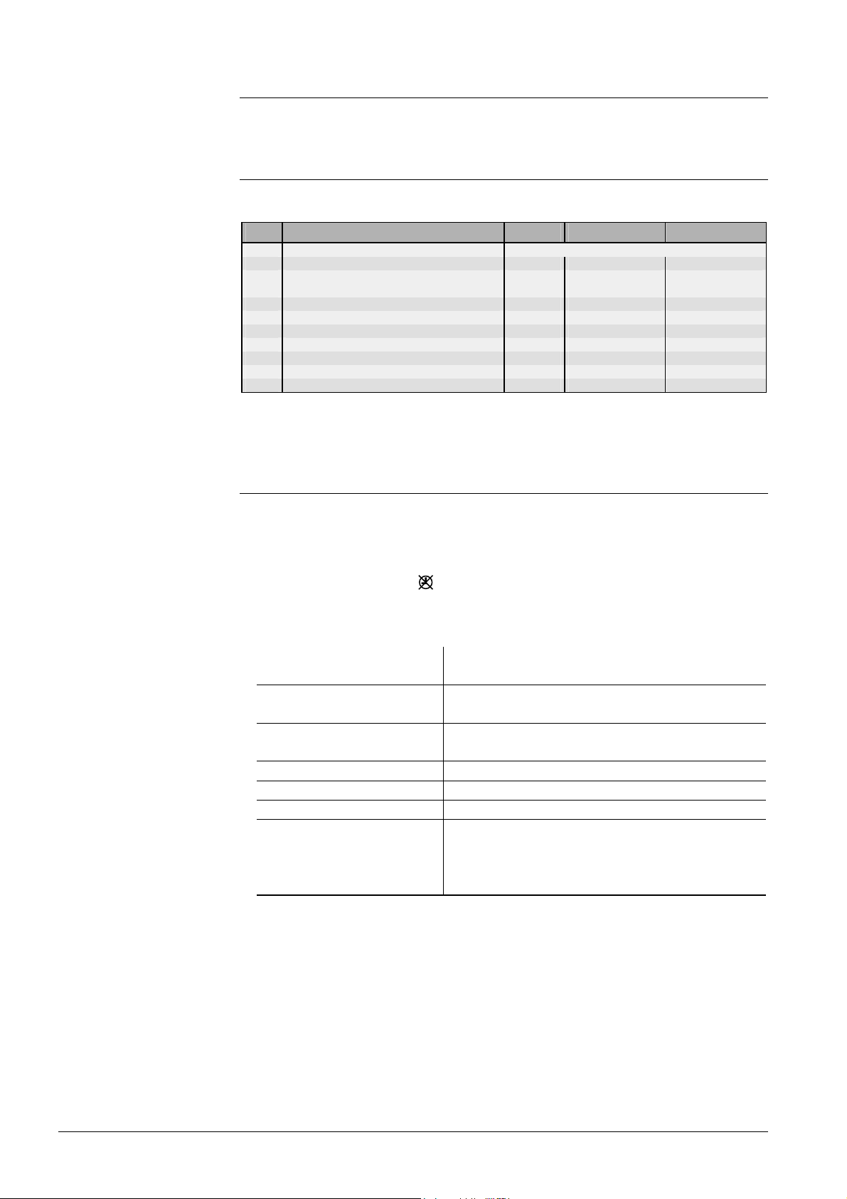
Line Function, parameter Unit Factory setting Range
1 Current room temperature setpoint Display function
2 Reduced room temperature setpoint °C 14 variable
3 Setpoint for frost protection / holiday mode °C 8 8...variable
5 Heating curve slope 15 2.5...40
6 Weekday for entering the heating program Current weekday 1…7, 1-7
7 Start of heating period 1 hh:min 06:00 --:-- / 00:00…24:00
8 End of heating period 1 hh:min 22:00 --:-- / 00:00…24:00
9 Start of heating period 2 hh:min --:-- --:-- / 00:00…24:00
10 End of heating period 2 hh:min --:-- --:-- / 00:00…24:00
11 Start of heating period 3 hh:min --:-- --:-- / 00:00…24:00
12 End of heating period 3 hh:min --:-- --:-- / 00:00…24:00
Notes on settings and explanations on every function block are given in the descriptions of the individual functions.
5.2 Settings and displays
• The nominal room temperature setpoint is adjusted with the setpoint knob. Its scale
is calibrated in °C room temperature. The room temperature will be maintained at the
adjusted setpoint:
− In automatic operation during the heating periods
− In continuous operation always
• On operating line 1, the LCD shows the current room temperature setpoint of each
heating circuit Depending on the operating mode and the operating state, the room
temperature setpoint can be:
Operating mode and operating state
Heating to the nominal setpoint
Heating to the reduced setpoint
Continuous operation Adjustment made with the setpoint knob
Quick setback Reduced setpoint (setting operating line 2)
Frost protection Setpoint for frost protection (setting operating line 3)
OFF by ECO • During heating periods: adjustment made with
• The reduced room temperature setpoint of each heating circuit is to be set sepa-
rately on operating line 2; at the top, the setting range is limited by the nominal set-
point; at the bottom, by the setpoint for frost protection. This is the setpoint main-
tained outside the heating periods
• The setpoint for frost protection of each heating circuit is to be set separately on
operating line 3; the setting range is from 8 °C (fixed value) to the adjusted reduced
setpoint. Hence, this frost protection acts as frost protection for the house or building.
At the same time, this setting represents the setpoint for the holiday mode. A holiday
program can be entered either on the controller or on the QAW70 room unit. For
Displayed setpoint
Adjustment made with the setting knob (incl. the
readjustment made on the room unit)
Reduced setpoint (setting operating line 2)
the setting knob (incl. the readjustment made on
the room unit)
• Outside heating periods: Reduced setpoint
28/126
Siemens Building Technologies Basic documentation RVD240 CE1P2384en
HVAC Products 5 Function block Space heating 27.05.2004
Page 29

more information, refer to chapter 9 (operating lines 31...33) and section 29.3
"Combination with room unit QAW70"
• The d.h.w. setpoint is to be set on operating line 4. Its setting range depends on the
type of plant (for detailed information, refer to chapter 15 "Function block D.h.w.
heating"
• The slope of the heating curve of each heating circuit to be set separately on operat-
ing line 5. The setting range is 2.5...40; the effective slope is 10 times smaller
For more detailed information, refer to section 12.3 "Heating curve "
The setpoints of the nominal temperature and of the reduced temperature as well as
that for frost protection operation are to be entered directly in °C room temperature.
They are independent of whether or not the control uses a room sensor. When using no
room temperature sensor, the heating curve or the room model will be considered.
5.3 Heating program
The heating program of the RVD240 provides a maximum of 3 heating periods per day;
also, every weekday can have different heating periods. Every heating period is defined
by a start and an end time.
Using "1-7" on operating line 6, it is possible to enter a heating program that applies to
all days of the week. This simplifies the settings: If the weekend times are different, first
enter the times for the entire week, then change days 6 and 7 as required.
The settings are sorted and overlapping heating periods combined.
By setting --:-- at the start or at the end, the heating period will be canceled.
With the QAW70 room unit, the heating program can be changed from a remote location.
29/126
Siemens Building Technologies Basic documentation RVD240 CE1P2384en
HVAC Products 5 Function block Space heating 27.05.2004
Page 30

6 Function block Clock settings
6.1 Operating lines
Line Function, parameter Unit Factory setting Range
13 Time of day hh:mm Undefined 00:00...23:59
14 Weekday d 1 1...7
15 Date dd.MM 01.01 01.01. ... 31.12.
16 Year yyyy 1995 1995...2094
6.2 Entries
The RVD240 has a yearly clock with the time of day, the weekday and the date.
The changeover from summer- to wintertime, and vice versa, takes place automatically.
Should the respective regulations change, the changeover dates can be adjusted (refer
to operating lines 144 and 145).
30/126
Siemens Building Technologies Basic documentation RVD240 CE1P2384en
HVAC Products 6 Function block Clock settings 27.05.2004
Page 31

7 Function block End-user d.h.w.
7.1 Operating lines
Line Function, parameter Unit Factory setting Range
17 Weekday for entering the d.h.w. program Current weekday 1...7, 1-7
18 Start of release period 1 hh:min 06:00 --:-- / 00:00...24:00
19 End of release period 1 hh:min 22:00 --:-- / 00:00...24:00
20 Start of release period 2 hh:min --:-- --:-- / 00:00...24:00
21 End of release period 2 hh:min --:-- --:-- / 00:00...24:00
22 Start of release period 3 hh:min --:-- --:-- / 00:00...24:00
23 End of release period 3 hh:min --:-- --:-- / 00:00...24:00
41 Setpoint d.h.w. temperature Normal °C 55 variable
42 Setpoint d.h.w. temperature Reduced °C 40 8…Normal setpoint
7.2 D.h.w. heating program
The d.h.w. heating program of the RVD240 provides a maximum of 3 release periods
per day; also, every weekday can have different release periods. Every release period
is defined by a start and an end.
Using "1-7" on operating line 17, it is possible to enter a d.h.w. heating program that
applies to all weekdays. This simplifies the settings: if the weekend times are different,
first enter the times for the entire week, then change days 6 and 7 as required.
The settings are sorted and overlapping release periods combined.
By setting --:-- at the start or at the end, the release period will be canceled.
However, d.h.w. heating can also be released according to other programs. The selection is to be made on operating line 101.
7.3 Adjustment of setpoints
• The nominal d.h.w. temperature setpoint is to be adjusted on operating line 41. Its
setting range depends on the type of plant (for details, refer to section 18.5).
• The reduced d.h.w. temperature setpoint can be adjusted on operating line 42 be-
tween 8 °C and the nominal setpoint. It is used with the d.h.w. program between the
release periods (refer to above section 7.3).
w
BW
Nom
Red
06:00 08:00 11:30 13:30 16:00
Nom Nominal setpoint
Red Reduced setpoint
t Time
wBW D.h.w. setpoint
2381D06
t
31/126
Siemens Building Technologies Basic documentation RVD240 CE1P2384en
HVAC Products 7 Function block End-user d.h.w. 27.05.2004
Page 32

8 Function block Display of actual sen-
sor values
8.1 Operating lines
Line Function, parameter Unit Factory setting Range
24 Room temperature (terminal A6) °C Display function
25 Outside temperature °C Display function
26 D.h.w. temperature °C Display function
27 Flow temperature heating circuit °C Display function
8.2 Displays
• Room temperature:
If a room sensor or room unit is connected to the PPS interface (A6), the acquired
temperature will be displayed separately for each heating circuit
• Outside temperature:
The displayed temperature is delivered by the analog outside sensor (connected to
B9) or via data bus (refer to subsection 20.2.4 "Outside temperature source".
If buttons
will be adopted as the composite and the attenuated outside temperature (outside
temperature reset)
• D.h.w. temperature:
The temperature displayed is that measured with the d.h.w. sensor. Depending on
the plant configuration, this can be d.h.w. flow sensor B3 (plant types x–4) or storage
tank sensor B31 (other plant types with the exception of x–0).
If button
• Flow temperature heating circuit:
The temperature displayed separately for each heating circuit is the temperature
measured with the relevant sensor.
If button
and are pressed for 3 seconds, the displayed outside temperature
or is pressed, the controller will display the current setpoint
or is pressed, the controller will display the current setpoint
32/126
Siemens Building Technologies Basic documentation RVD240 CE1P2384en
HVAC Products 8 Function block Display of actual sensor values 27.05.2004
Page 33

9 Function block Holiday settings
9.1 Operating lines
Line Function, parameter Unit Factory setting Range
31 Holiday period 1 1...8
32 Date of first day of holiday --:-- 01.01 ... 31.12.
33 Date of last day of holiday --:-- 01.01 ... 31.12.
9.2 Holiday program
A maximum of 8 holiday periods per year can be programmed. At 00:00 of the first day
of the holiday period, changeover to the setpoint for frost protection / holiday mode
takes place. At 24:00 of the last day of the holiday period, the controller will change to
normal or reduced heating in accordance with the time switch settings.
The settings of each holiday period will be cleared as soon as the respective period has
elapsed.
Holiday periods may overlap. It is not necessary to observe a certain order. Depending
on the entry made on operating line 125 (assignment of d.h.w.), the holiday function will
switch off d.h.w. heating and the circulating pump.
The holiday program is only active in AUTO mode and applies to both heating circuits.
33/126
Siemens Building Technologies Basic documentation RVD240 CE1P2384en
HVAC Products 9 Function block Holiday settings 27.05.2004
Page 34

10 Function block Indication of errors
10.1 Operating line
Line Function, parameter Unit Factory setting Range
50 Indication of errors Display function
10.2 Indication of errors
Faults in the measuring circuits that are detected by the controller are indicated on the
display as
Error code Cause
* If maximum limitation of the secondary return temperature is activated (by making an entry on operating line
177; lowering against the primary limit value), no error message will be delivered
Er (error) and appear on operating line 50 with an error code:
10 Error outside sensor B9
30 Error flow sensor heating circuit 1 (B1)
32 Error flow sensor B12
40 Error primary return sensor B7*
42 Error return sensor B71
43 Error return sensor B72
50 Error d.h.w. sensor B31
52 Error d.h.w. sensor B32
54 Error d.h.w. flow sensor B3
61 Error room unit heating circuit 1
62 Unit with wrong PPS identification connected heating circuit 1
66 Error room unit heating circuit 2
67 Unit with wrong PPS identification connected heating circuit 2
81 Short-circuit on data bus (LPB)
82 2 units with the same bus address (LPB)
86 Short-circuit PPS
100 2 clock time masters
120 Flow alarm common flow temperature
121 Flow alarm heating circuit flow heating circuit 1
122 Flow alarm heating circuit flow heating circuit 2
123 Flow alarm d.h.w. flow
140 Inadmissible bus address (LPB)
171 Alarm at input H5
180 Connection to heat meter at input H5 interrupted
181 Wrong configuration between operating lines 52 and 57
182 Wrong configuration between operating lines 52, 176 and 177 or
between 52 and 179
183 Wrong configuration between operating lines 171 and 177 or 176
34/126
Siemens Building Technologies Basic documentation RVD240 CE1P2384en
HVAC Products 10 Function block Indication of errors 27.05.2004
Page 35

11 Function block Plant configuration
11.1 Operating lines
Line Function, parameter Unit
51 Plant type 1–0 1–0...4–9
52 Function of input at terminal B71 / U1 1 0...3
54 Function of circulating pump 0 0...3
55 Function of the contact connected to terminal H5 0 0...4
56 Action of pulse input on the heating circuits 1 1...3
57 Assignment of variable speed pump control 0 0...4
58 Minimum speed of the speed-controlled pump % 50 0...variable
59 Maximum speed of the speed-controlled pump % 100 Variable ...100
60 Power factor at reduced pump speed % 85 0...100
Factory
setting
Range
11.2 Parameters to be set
By selecting the required plant type and by making entries regarding the
• circulating pump
• functions at terminals B71 / U1 and H5
• speed-controlled pump
all functions and settings required for the configured type of plant or the assigned operating lines will be activated. All the other operating lines will be deactivated and hidden.
11.2.1 Plant type
The type of plant is to be entered on operating line 51.
The plant types have the following features:
• The RVD240 has a total of 14 plant types preprogrammed. For detailed information,
refer to subsection 3.1.2 "Plant types"
• Plant types x–0 only provide flow temperature control in the heating circuits; d.h.w.
heating is not possible
• In terms of space heating, it is possible to have mixing or pump heating circuits
• The d.h.w. can be heated by a
− coil type storage heater
− heat exchanger
− stratification storage tank
• Actuating device can be an intermediate circuit pump, charging pump, circulating
pump or mixing valve
11.2.2 Input B71 / U1
The function of input (terminal) B71 / U1 must be selected on operating line 52. The
following choices exist:
• Setting 0:
The RVD240 interprets the connected sensor as a differential temperature sensor
• Setting 1:
The connected sensor is used in a heating or d.h.w. circuit as a return temperature
sensor. It is to be noted that when using a speed-controlled pump, sensor B71 must
always be present in the return of the respective control loop
• Setting 2:
The RVD240 can receive DC 0...10 V signals from a plant element and then pass
them on via M-bus. Plant element can be a differential pressure sensor, for instance.
The signals have no impact on the control functions of the RVD240
35/126
Siemens Building Technologies Basic documentation RVD240 CE1P2384en
HVAC Products 11 Function block Plant configuration 27.05.2004
Page 36

• Setting 3:
B71 / U1 acts as a scalable DC 0…10 V input to receive the heat demand signals
from other devices
11.2.3 Circulating pump
The circulating pump is to be configured on operating line 54.
0 = no circulating pump present
1 = the circulating pump feeds water into the storage tank; this takes place only when
d.h.w. heating is activated
2 = the circulating pump feeds water into the heat exchanger’s secondary return,
whereby 80 % of the heat losses will be compensated for
3 = the circulating pump feeds water into the heat exchanger’s secondary return,
whereby 100 % of the heat losses will be compensated for
When using setting 2 or 3, the circulating pump runs during the whole period of time
d.h.w heating is released. (also refer to subsection 16.3.6 "Compensation of heat losses through control ".
11.2.4 Input H5
Terminal H5 of the RVD240 is a digital input. It offers the following choices (settings on
operating line 55):
0 = No function
1 = reception of pulses
with plant type 1–x, the mode of operation of the pulse input must be defined on
operating line 56:
1 = acting only on heating circuit 1
2 = acting only on heating circuit 2
3 = acting on both heating circuits
With the other plant types, the function always acts on 2-port valve Y1 in the pri-
mary return.
For more detailed information, refer to chapter 27 "Function block Various func-
tions " (operating lines 181 through 183).
2 = reception of heat demand signals
for more information, refer to chapter 13 "Function block Valve actuator of heat
converter"
3 = input for alarm signals:
it is possible to receive error messages in the form of pulses. Operating line 50
displays them with error code 171; they can be passed on via LPB or M-bus
4 = input for flow switch:
to improve the control performance, it is possible to fit an optional flow switch in the
d.h.w. circuit of several types of plant.
The unit connected to H5 must have gold-plated contacts; if AC 230 V has passed
through such contacts, they cannot be used again.
11.2.5 Control of variable speed pump
Use
The RVD240 features a pulse-width-modulated output that is used for the control of a
variable speed pump. Based on the temperature conditions, the controller calculates
the ideal speed of the pump. The speed-controlled pump is to be selected on operating
line 57. This can be:
Setting Terminal Used as:
0 – None
1 Q1 Heating circuit pump in heating circuit 1
2 Q2 Heating circuit pump in heating circuit 2
36/126
Siemens Building Technologies Basic documentation RVD240 CE1P2384en
HVAC Products 11 Function block Plant configuration 27.05.2004
Page 37

Minimum and maximum
pump speed
Control of the heating
circuit pump
3 Q3
Intermediate circuit pump in connection with coil type storage
tanks
4 Q4
Storage tank charging pump in connection with stratification
storage tanks
In manual operation, the speed-controlled pump runs at the nominal speed.
The intermediate circuit pump used in connection with stratification storage tanks and
circulating pump K6 are not speed-controlled.
If the pulse-width-modulated output is assigned to a pump that is not used by the respective plant type, it remains at 0 %.
• The minimum pump speed in % of the nominal speed is to be set on operating line
58. It should be as low as possible, but high enough to ensure that all consumers receive sufficient amounts of heat. The relay assigned to the pump is still connected in
parallel and can be used to fully deactivate the pump when not in use.
The setting range reaches from 0 to the value set on operating line 59
• The maximum pump speed in % of the nominal speed is to be set on operating
line 59.
If, due to the hydraulic layout, the maximum pump head must be reduced, this
should be done via a reduction of the maximum pump speed since this saves pumping power.
If the pump may operate at nominal capacity, the maximum speed is to be maintained at 100 %.
The setting range reaches from the value set on operating line 58 to 100 %
The following illustration shows the control of the heating circuit pump. It shows the
pump speed and the flow and return temperatures as a function of the outside temperature.
In the upper outside temperature range (range 1; in the example T
= 20...–5 °C), the
A
pump speed is maintained at its minimum until the flow temperature – according to the
heating curve – would exceed the flow temperature setpoint T
In the lower outside temperature range (range 2; in the example T
flow temperature is then maintained at a constant level of T
(operating point C).
Vmax
= –5...–10 °C), the
A
. But the pump speed is
Vmax
continuously increased until the selected maximum speed is reached (operating point
A; T
= –10 °C).
A
The heating output at operating point A is the same as the heating output that would
result at operating point B (flow temperature according to the heating curve, minimum
pump speed).
37/126
Siemens Building Technologies Basic documentation RVD240 CE1P2384en
HVAC Products 11 Function block Plant configuration 27.05.2004
Page 38

T
V
100
Maximum flow temperature
Power factor
90
80
70
60
50
40
30
20
10
0
20
A Operating point A (maximum pump speed reached) T
B Operating point B (theoretical heat output) T
C Operating point C (effective heat output) T
n
Maximum pump speed
max
Reduced pump speed
n
red
15
T
HKm
10 5
TV for n
Range 1 Range 2
TV for n
max
red
TR for n
max
n
red
T
= 70 °C
Vmax
C
TR for n
red
0
HKm
Return temperature
RL
Flow temperature
V
T
Vmax
-5 -10
Mean radiator temperature
Maximum limit value of flow tempera-
ture
B
A
n
max
2383D08e
T
AM
Notes on the example given in the illustration:
• The heating plant is designed such that it reaches its maximum capacity at an outside
temperature of –10 °C (no more spare capacity for heating up processes). At this
outside temperature, both the pump speed and the flow temperature are at their
maximum
• With this kind of plant design, it can be assumed that the outside temperature hardly
ever drops below –5 °C. But the pump speed will also be increased above its minimum
in the case of heating up processes, when the outside temperature is above –5 °C
Lower pump speeds mean:
• Energy savings due to reduced pumping power
• Greater differential between heating flow and return temperature
• Lower return temperatures
The heating circuit is controlled based on the signal received from the heating circuit
flow sensor.
Setting of the maximum flow temperature (operating line 95) defines the maximum flow
temperature setpoint on the one hand. On the other, the same setting defines the range
from what flow temperature the pump speed shall be increased.
The maximum flow temperature should always be selected as high as this is permitted
by the heating system. The higher the flow temperature setting, the longer the pump
runs at minimum speed. Also, the heating circuit’s maximum output will not be restricted unnecessarily.
The illustration shows that at outside temperatures below operating point C, the pump
speed will be increased from minimum to maximum. To define the rate at which the pump
speed shall be increased, the radiators’ power factor is to be set. The power factor is the
ratio of radiator output at minimum pump speed and that at maximum pump speed:
Power factor =
Radiator output at maximum speed
The factory setting is 85 %. If the plant is correctly sized, this setting ensures a satisfactory performance and, for this reason, necessitates readjustments only in exceptional
38/126
Siemens Building Technologies Basic documentation RVD240 CE1P2384en
HVAC Products 11 Function block Plant configuration 27.05.2004
Radiator output at minimum speed
Page 39

Control of the intermediate circuit pump
Control of the storage
tank charging pump
cases. Incorrect settings only have an impact at extremely low outside temperatures;
these are small however.
The power factor of the variable speed pump at minimum speed is to be set on operating line 60.
If, with plant types 2–x, 3–x and 4–x, the common flow temperature is not reached, the
speed of the heating circuit pump will not change because speed control only acts on
the heating circuit pump.
The intermediate circuit pump operates at maximum speed until the limit of maximum
return temperature limitation is exceeded. Then, the pump speed is continuously reduced, giving the heating water more time to transfer its heat to the storage tank.
The intermediate circuit pump is controlled according to the signal received from the
closest return sensor. The following setpoints and actual values are used:
Plant type Actual value
Setpoint
(sensor)
2–1, 3–1,
2–2
B71
[Maximum setpoint of the return temperature during d.h.w.
heating*] minus [differential to the primary limit value with
maximum limitation of the secondary return temperature**]
1–3, 1–9 B71
4–9 B72
* Setting value operating line 176
** Setting value operating line 177
Maximum setpoint of the return temperature with d.h.w.
heating
The d.h.w. flow temperature setpoint should be maintained as accurately as possible,
allowing the storage tank can be fully charged in one go. At the beginning of d.h.w.
heating, the storage tank charging pump starts at minimum speed until the d.h.w. flow
temperature setpoint is reached. Then, the pump speed is continuously increased. During the charging process, the storage tank charging pump reduces its speed only if
there is not sufficient heat available.
The storage tank charging pump is controlled according to the d.h.w. flow temperature
acquired with sensor B3; setpoint is the current d.h.w. temperature setpoint.
39/126
Siemens Building Technologies Basic documentation RVD240 CE1P2384en
HVAC Products 11 Function block Plant configuration 27.05.2004
Page 40

12 Function block Space heating
12.1 Operating lines
Tip
Line Function, parameter Unit
61 Heating limit (ECO) K –3 --- / –10...+10
62 Building time constant h 20 0...50
70 Effect of the room temperature (gain factor) 10 0...20
71 Parallel displacement of the heating curve K 0.0 –15.0...+15.0
72 Pump overrun time heating circuit pump min 4 0...40
73 Maximum limitation of room temperature K --- --- / 0.5...4
74 Optimization with / without room temperature sensor 0 0 / 1
75 Maximum heating up time h 0:00 0:00...42:00
76 Maximum early shutdown h 0:00 0:00...6:00
77 Maximum rate of flow temperature increase °C/h --- --- / 1...600
78 Quick setback 1 0 / 1
Factory
setting
Range
12.2 Compensating variables
12.2.1 Outside temperature
The RVD240 makes use of 3 types of outside temperatures:
• The actual outside temperature (T
• The composite outside temperature (T
side temperature by the building time constant. The proportion of the actual outside
temperature is 50 %.
The composite outside temperature suppresses unnecessary reactions of the control
system if the outside temperature changes for short periods of time.
In the case of the weather-compensated control (without or with room influence), the
RVD240 uses the composite outside temperature.
The building time constant is a measure of the type of building construction and indicates how quickly the room temperature would change if the outside temperature
suddenly changed. The building time constant is adjustable and applies to both heating circuits:
Type of building construction Recommended building time constant
Light 10 h
Medium 20 h
Heavy 50 h
• The attenuated outside temperature (TAD). It is generated by filtering twice the actual
outside temperature by the building time constant. This means that, compared with
the actual outside temperature, the attenuated outside temperature is considerably
dampened. This ensures that no heating will take place in the summer when, under
normal circumstances, the heating would be switched on because the outside temperature drops for a few days
If operating line 25 is selected (display of the actual room temperature) and the two
buttons
and are pressed simultaneously for about 3 seconds, the attenuated and
the composite outside temperature will generate the current measured value; the generation of these two variables will then start anew (outside temperature reset).
)
A
). It is generated by filtering the actual out-
AM
40/126
Siemens Building Technologies Basic documentation RVD240 CE1P2384en
HVAC Products 12 Function block Space heating 27.05.2004
Page 41

T
A
25
20
15
10
5
0
T
AD
T
A
T
AM
2522D17
t
Progression of the actual, composite and attenuated outside temperature
TA Actual outside temperature
TAD Attenuated outside temperature
TAM Composite outside temperature
t Time
12.2.2 Room temperature
The room temperature is included in the control process as follows:
• With room temperature-compensated flow temperature control, the deviation of the
actual room temperature from the room temperature setpoint is the only compensating variable
• With weather-compensated flow temperature control with room temperature influ-
ence, it is an additional compensating variable
The gain factor for the room temperature influence can be adjusted (operating line 70).
This factor indicates to what extent a deviation in the room changes the room temperature setpoint, thus having an indirect impact (via the slope) on the flow temperature
control:
0 = room temperature deviations have no impact on the generation of the setpoint
20 = room temperature deviations have a maximum impact on the generation of the
setpoint
A room temperature sensor is mandatory (room unit).
E
wR - x
2462D05
R
Gain factor of room temperature deviation
–∆w
Decrease of room temperature setpoint
R
+∆w
Increase of room temperature setpoint
R
E Effect
w
Setpoint minus actual value (room temperature)
R–xR
The setpoint change ∆w
is calculated in the static state according to the following for-
R
mula:
∆w
Factor of room influence E
=
R
2
× ( wR - xR )
41/126
Siemens Building Technologies Basic documentation RVD240 CE1P2384en
HVAC Products 12 Function block Space heating 27.05.2004
Page 42

S
2462D06
Impact of the room temperature setpoint change on the flow temperature setpoint
∆w
Change of room temperature setpoint
R
s Heating curve slope
∆w
Change of flow temperature setpoint
VT
The flow temperature setpoint change ∆w
is calculated according to the following
VT
formula:
∆w
= ∆w
VT
× ( s × 0.1 + 1 )
R
12.3 Heating curve
With both types of weather-compensated flow temperature control (with / without room
temperature influence), the heating curve ensures the assignment of the flow temperature setpoint to the outside temperature. Its slope for each heating circuit is to be set
separately on operating line 5.
T
V
110
100
90
80
70
60
50
40
s
=
40 35 32,5 30
27,5
25 22,5
20
17,5
15
12,5
10
7,5
5
30
20
20
15 10
0
5
-10
-5
-15
-20
-25 -30 -35
2,5
2381D05
T
AM
Heating curve
s Slope
TAM the composite outside temperature
TV Flow temperature
The heating curve has a fixed tilting point at an outside temperature of 22 °C and a flow
temperature of 20 °C. It can be set around this tilting point in the range from 2.5 to 40 in
increments of 0.5.
Each heating curve has a substitute line which intersects the tilting point and ”its” heating curve at an outside temperature of 0 °C. Its slope is set on the controller and is calculated as follows:
10 ×
∆T
s =
∆T
AM
V
The use of a substitute line is required because the heating curve is slightly deflected.
This is necessary to compensate for the nonlinear radiation characteristics of the different types of radiators.
42/126
Siemens Building Technologies Basic documentation RVD240 CE1P2384en
HVAC Products 12 Function block Space heating 27.05.2004
Page 43

The basic setting is made according to the planning documentation or in compliance
with local practices.
The heating curve is valid for a room temperature setpoint of 20 °C.
If operation is not satisfactory with the basic setting, it is possible to manually enter a
permanent parallel displacement of the heating curve on operating line 71.
12.4 Generation of setpoint
The setpoint is always generated as a function of the demand for heat. It is generated
based on the heat demand of the heating circuits and of the d.h.w. circuit.
The heat demand of the heating circuits is determined either by weather-compensation,
weather-compensation with room influence or room-compensation.
12.4.1 Display of setpoint
The effective setpoint generated by the controller as a result of the different influencing
factors can be displayed on operating line 27 by keeping button
12.4.2 Setpoint of weather-compensated control
The setpoint is generated via the heating curve as a function of the outside temperature.
The temperature used is the composite outside temperature.
or depressed.
2383B01
T
AM
H
/ /
T
Rw
ss
T
Vw
Generation of setpoint with weather-compensated control without a room unit
*
H Heating curve
s
Composite outside temperature
T
AM
T
Room temperature setpoint
Rw
TVw Flow temperature setpoint
Operating line 5 Setting of heating curve slope
Operating line 71 Setting the parallel displacement of the heating curve
Multiplier
Heating curve slope
43/126
Siemens Building Technologies Basic documentation RVD240 CE1P2384en
HVAC Products 12 Function block Space heating 27.05.2004
Page 44
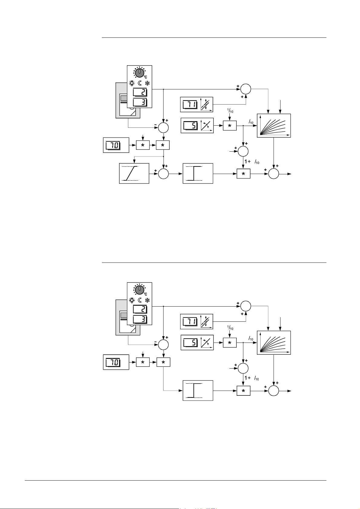
12.4.3 Setpoint of room-compensated control
The setpoint is generated based on the deviation of the actual room temperature from
the setpoint. In addition, the heating curve at a fixed outside temperature of 0 °C is
taken into consideration.
2383B02
/ /
T
Rw
0 °C
T
Rx
1
/
2
ss
H
E
1
+10 K
I
-10 K
+50 K
L
-50 K
s
T
Vw
Generation of setpoint with room-compensated control
* Multiplier TRw Room temperature setpoint
E Room influence TRx Actual value of the room temperature
H Heating curve TVw Flow temperature setpoint
I Integrator with limiter Operating line 5 Setting the heating curve slope
L Limiter Operating line 70 Setting the gain factor for room influence
s Heating curve slope Operating line 71 Setting the parallel displacement of the heating curve
12.4.4 Setpoint of weather-compensated control with room
Here, in addition to the outside temperature and the room temperature setpoint, the
heating curve and the room influence act on the flow temperature setpoint.
influence
2381B03
/ /
T
Rx
1
T
Rw
T
AM
ss
/
2
H
E
1
+50 K
L
-50 K
s
T
Vw
Generation of setpoint with weather-compensated control with room influence
* Multiplier TRw Room temperature setpoint
E Room influence TRx Actual value of the room temperature
H Heating curve TVw Flow temperature setpoint
L Limiter Operating line 5 Setting the heating curve slope
s Heating curve slope Operating line 70 Setting the gain factor for room influence
TAM Composite outside temperature Operating line 71 Setting the parallel displacement of the
heating curve
44/126
Siemens Building Technologies Basic documentation RVD240 CE1P2384en
HVAC Products 12 Function block Space heating 27.05.2004
Page 45

12.5 Heating circuit control
Both heating circuits are controlled separately.
12.5.1 Weather-compensated control
Prerequisites for this type of control:
• Outside sensor connected
• No room unit connected or, if connected, room influence set to 0 (minimum)
The compensating variable for weather-compensated control is the composite outside
temperature. The assignment of the flow temperature setpoint to the compensating
variable is made via the set heating curve. The room temperature will not be taken into
consideration.
Main application of this type of control are plants or buildings in which
• several rooms are occupied at the same time
• none of the rooms is suited as a reference room for the room temperature
12.5.2 Room-compensated control
Prerequisites for this type of control:
• Room unit connected
• No outside sensor connected
If no outside sensor is connected, the setting on operating line 70 (room influence) is
inactive.
The compensating variable for room-compensated control is the deviation of the actual
room temperature from the setpoint from which the room influence is generated. In addition, an assumed outside temperature of 0 °C is included in the setpoint generation.
• When there is no room temperature deviation, the controller maintains the flow tem-
perature setpoint generated by the heating curve slope at an outside temperature of
0 °C
• Any room temperature deviation produces an instant parallel displacement of the set
heating curve. The correlation between the amount of the deviation and the extent of
the displacement is defined by the room influence. The room temperature is de-
pendent on the
− deviation of the actual room temperature from the setpoint
− set heating curve slope
− set room authority
The purpose of the room influence is to exactly reach the required setpoint during the
control process and to maintain it.
This type of control operates as PI control. The I-part ensures that any deviations from
the room temperature setpoint will be compensated with no offset.
Main application of this type of control are plants or buildings where one of the rooms is
suited as a reference room for the room temperature.
12.5.3 Weather-compensated control with room influence
Prerequisites for this type of control:
• Outside sensor connected
• Room unit connected
• Room influence set in the range 1...20
Compensating variables for weather-compensated control with room influence are
• the composite outside temperature
• the setpoint / actual value deviation of the room temperature
The flow temperature setpoint is continuously shifted via the heating curve by the composite outside temperature. In addition, any deviation of the room temperature pro-
45/126
Siemens Building Technologies Basic documentation RVD240 CE1P2384en
HVAC Products 12 Function block Space heating 27.05.2004
Page 46

duces an instant parallel displacement of the heating curve. The correlation between
the amount of the deviation and the extent of the displacement is defined by the room
influence. The room temperature is dependent on the
• set room authority
• deviation of the actual room temperature from the setpoint
• set heating curve slope
These 3 factors are used to generate the correcting variable for the flow temperature
setpoint.
Main application of this type of control are well insulated buildings or buildings with
considerable heat gains where
• several rooms are occupied at the same time
• 1 of the rooms is suited as a reference room for the room temperature
12.6 Automatic ECO function
12.6.1 Fundamentals
The automatic ECO function is active with all plant types. It controls the heating system
depending on demand. This function gives consideration to the development of the
room temperature depending on the type of building construction and as a function of
the outside temperature. If the amount of heat stored in the house or building is sufficient to maintain the room temperature setpoint currently required, the ECO function
will switch the heating off (valve fully closed, heating circuit pump off).
The automatic ECO function acts separately on both heating circuits.
Action of the automatic ECO function means:
• Heating circuit pump OFF; it can only be activated by frost protection for the plant
• Heating circuit mixing valve CLOSED
In the individual operating modes, the automatic ECO function behaves as follows:
Operating mode Automatic ECO function is …
Automatic operation active
Continuous operation inactive
Standby active
manual operation inactive
In the case of the RVD240, the automatic ECO function is subdivided into 2 part functions. ECO function 1 is used primarily in the summer, ECO function 2 responds mainly to
short-term temperature changes and, therefore, is active during intermediate seasons.
When using the automatic ECO function, the heating system operates only, or consumes energy only, if needed.
If required, the automatic ECO function can be deactivated.
12.6.2 Compensating variables and auxiliary variables
Note
Also refer to subsection 12.6.2.
The automatic ECO function necessitates outside sensor. As a compensating and auxiliary variable, the ECO function takes into account the development of the outside
temperature. The following variables are taken into consideration:
• Type of building construction
• The actual outside temperature (T
)
A
• The attenuated outside temperature. Compared to the actual outside temperature,
the attenuated outside temperature is significantly damped. This ensures that no
heating will take place in the summer when, under normal circumstances, the heating would be switched on because the outside temperature drops for a few days
46/126
Siemens Building Technologies Basic documentation RVD240 CE1P2384en
HVAC Products 12 Function block Space heating 27.05.2004
Page 47

• The composite outside temperature (T
). Since the composite outside temperature
AM
is attenuated compared to the actual outside temperature, it represents the effects of
short-time outside temperature variations on the room temperature as they often oc-
cur during intermediate seasons (spring time and autumn)
The thermal inertia of the house or building in the case of outside temperature variations is taken into account by including the composite outside temperature in the automatic ECO function.
12.6.3 Heating limit
The automatic ECO function necessitates a heating limit. An ECO temperature can be set
separately for each heating circuit in the range –10 K...+10 K (operating line 61). From
this setting value and the room temperature setpoint, the heating limit will be calculated.
The switching differential of 1 K for switching on / off is entered as a fixed value.
12.6.4 Mode of operation of ECO function 1
ECO function 1 operates as an automatic summer / winter function. The heating will be
switched off (mixing valve closed and heating circuit pump off) when the attenuated
outside temperature exceeds the heating limit.
The heating will be switched on again when all 3 outside temperatures have dropped
below the heating limit by the amount of the switching differential.
The heating limit is determined as follows:
Heating limit = T
RwN
+ T
(nominal room temperature setpoint plus ECO temperature).
ECO
Example
Example
A nominal room temperature setpoint w
of +20 °C and an ECO temperature T
N
ECO
of
–5 K result in a heating limit of +15 °C.
12.6.5 Mode of operation of ECO function 2
ECO function 2 operates as an automatic 24-hour heating limit. The heating will be
switched off (mixing valve closed and heating circuit pump off) when the actual or the
composite outside temperature exceeds the heating limit.
The heating will be switched on again when all 3 outside temperatures have dropped
below the heating limit by the amount of the switching differential.
The heating limit is determined as follows:
Heating limit = T
Rw akt
+ T
(current room temperature setpoint plus ECO tempera-
ECO
ture).
In contrast to ECO function 1, function 2 also considers when reduced heating is used.
A current room temperature setpoint T
of +18 °C and an ECO temperature of T
Rw akt
ECO
of –5 K result in a heating limit of +13 °C.
The heating limit has a minimum limitation; it cannot be lower than 2 °C.
12.7 Pump overrun
Pump overrun for the heating circuit pump can be set in the range 0...40 minutes (operating line 72). Setting 0 deactivates pump overrun.
12.8 Maximum limitation of the room temperature
The room temperature for each heating circuit can be separately limited to a maximum
value. For that purpose, a room sensor is required (sensor or room unit).
The limit value is generated from the nominal room temperature setpoint plus the value
entered on operating line 73.
47/126
Siemens Building Technologies Basic documentation RVD240 CE1P2384en
HVAC Products 12 Function block Space heating 27.05.2004
Page 48

Settings
With room sensor
Without room sensor
When the limit value is reached, the heating circuit pump will be deactivated until the
room temperature has again dropped below the setpoint.
Maximum limitation of the room temperature is independent of the setting used for the
room influence.
12.9 Optimization
12.9.1 Definition and purpose
Operation of the heating system is optimized. According to EN 12098, optimization is
the "automatic shifting of the switch-on and switch-off points aimed at saving energy".
This means that:
• Switching on and heating up as well as switching off are controlled such that during
building occupancy times the required room temperature level will always be ensured
• The smallest possible amounts of energy will be used to achieve this objective
Optimization acts separately on each heating circuit; all settings are made separately
per heating circuit.
12.9.2 Fundamentals
It is possible to select or set:
• Operating line 74: Type of optimization
0 = according to the room model with no room temperature sensor
1 = with room temperature sensor or room unit
• Operating line 75: Maximum limit value for the heating up time
• Operating line 76: The maximum limit value for optimum shutdown
• Operating line 78: Quick setback: yes or no
To perform the optimization function, the controller makes use of the actual room temperature – acquired by a room temperature sensor or room unit – or the room model.
An outside sensor is always required.
Using a room sensor or room unit, it is possible to have optimum start and optimum
stop control.
To be able to optimally determine the switch-on and switch-off points, optimization
needs to "know" the building's heating up and cooling down characteristics, always as a
function of the prevailing outside temperature. For this purpose, optimization continually
acquires the room temperature and the respective outside temperature. It captures
these variables via the room temperature sensor and the outside sensor and continually adjusts the forward shift of the switching points. In this ways, optimization can also
detect changes made to the house or building and to take them into consideration.
The learning process always concentrates on the first heating period per day.
Without a room temperature sensor, the following functions can be provided:
• Optimum start control. Optimum start control operates with fixed values (no learning
process), based on the set maximum heating up time and the room model
• Quick setback. Quick setback operates with fixed values (no learning process),
based on the set maximum heating up time and the room model
48/126
Siemens Building Technologies Basic documentation RVD240 CE1P2384en
HVAC Products 12 Function block Space heating 27.05.2004
Page 49

12.9.3 Process
HP Heating program t3 Quick setback
TR Room temperature TRw Room temperature setpoint
t Time T
t
Forward shift for early shutdown T
1
t2 Forward shift for the start of heating up TRx Actual value of the room temperature
12.9.4 Room model temperature
Setpoint of normal room temperature
Rw
Setpoint of reduced room temperature
Rw
To ascertain the room temperature generated by the room model, a distinction must be
made between two cases:
• The RVD240 is not in quick setback mode:
The room temperature generated by the room model is identical to the current room
temperature setpoint
• The RVD240 is in setback mode:
The room temperature generated by the room model is determined according to the
following formula:
Room model temperature TRM = ( TRw - TAM ) × e
t
3
× kt
+ TAM
T
Rw
T
T
Rw
T
Rw
RM
2522D18
t
1
Development of the room temperature generated by the room model
e 2.71828 (basis of natural logarithms) TR Room temperature
k
Building time constant TRM Room model temperature
t
t Time in hours T
Quick setback T
t
1
T
Composite outside temperature
AM
Setpoint of normal room temperature
Rw
Setpoint of reduced room temperature
Rw
49/126
Siemens Building Technologies Basic documentation RVD240 CE1P2384en
HVAC Products 12 Function block Space heating 27.05.2004
Page 50

12.9.5 Optimum stop control
During the building's occupancy time, the RVD240 maintains the setpoint of normal
heating. Towards the end of the occupancy time, the control switches to the reduced
setpoint. Optimization calculates the changeover time such that, at the end of occupancy, the room temperature will be 0.5 °C below the setpoint of normal heating (optimum shut-down).
By entering 0 hours as the maximum optimum shutdown, optimum stop control can be
deactivated.
12.9.6 Quick setback
When changing from the normal temperature to a lower temperature level (reduced or
holidays / frost), the heating will be shut down. And it will remain shut down until the
setpoint of the lower temperature level is reached.
• When using a room sensor, the effective actual value of the room temperature is
taken into account
• When using no room sensor, the actual value is simulated by the room model
The duration is determined according to the following formula
TRw - TAM
t = 3 × k
ln Natural logarithm
kt Building time constant [h]
t Duration of quick setback [h]
TAM Composite outside temperature
TRw Setpoint of normal room temperature
TRw Setpoint of reduced room temperature
× (– ln
t
- TAM
T
Rw
)
12.9.7 Optimum start control
During the building's non-occupancy times, the RVD240 maintains the setpoint of reduced heating. Towards the end of the nonoccupancy time, optimization switches the
control to the normal setpoint. Optimization calculates the changeover time such that,
at the start of occupancy, the room temperature will have reached the setpoint of normal heating.
When the room temperature is simulated by the room model, that is, when using no
room temperature sensor, the forward shift in time is calculated as follows:
t = ( T
kt Building time constant [h]
t Forward shift [min]
T
Rw
T
RM
– TRM ) × 3 × kt
Rw
Setpoint of normal room temperature
Room model temperature
Optimum start control with the room model takes place only if, previously, quick setback
took place.
Optimum start control can be deactivated by entering 0 hours as the maximum heating
up period.
50/126
Siemens Building Technologies Basic documentation RVD240 CE1P2384en
HVAC Products 12 Function block Space heating 27.05.2004
Page 51

Function
Effect on d.h.w. heating
12.9.8 Maximum rate of flow temperature increase
T
Vw
∆T
T
Vw
Maximum rise: =
Vw
––––––––
∆t
t
t Time
∆t Unit of time
TVw Flow temperature setpoint
∆T
Rate of setpoint increase per unit of time
Vw
2522D07
t
For each heating circuit, the rate of increase of the flow temperature setpoint can be
separately limited to a maximum. In that case, the maximum rate of increase of the flow
temperature setpoint is the selected temperature per unit of time (°C per hour). This
function
• prevents cracking noises in the piping
• protects objects and construction materials that are sensitive to quick temperature
increases (e.g. antiquities)
• prevents excessive loads on heat generating equipment
The limit value is to be set on operating line 77.
This function can be deactivated (setting ---).
Limitation of the rate of increase does not act on the d.h.w. circuit.
12.10 Frost protection for the building
12.10.1 General
Frost protection for the building acts separately on both heating circuits. It makes certain that the room temperature will not fall below a certain level. If the room temperature
falls below the setpoint for frost protection, the controller will maintain a room temperature equivalent to that setpoint plus the switching differential of 1 K.
For this purpose, both the controller and the heat source must be ready to operate
(mains voltage present).
The setpoint for frost protection is to be set on the end-user level, operating line 3.
This function cannot be deactivated.
12.10.2 Mode of operation with room sensor
The controller compares the room temperature with the adjusted setpoint for frost protection. If the room temperature falls below that setpoint, the controller will activate the
heating circuit pump to maintain the flow temperature at that setpoint plus the switching
differential of 1 K.
With the room temperature sensor, frost protection for the building has priority over the
ECO function.
12.10.3 Mode of operation without room sensor
The controller continually determines the room temperature as a function of the flow
temperature.
51/126
Siemens Building Technologies Basic documentation RVD240 CE1P2384en
HVAC Products 12 Function block Space heating 27.05.2004
Page 52

If the room temperature falls below the adjusted setpoint for frost protection, the controller will activate the heating circuit pump and control the flow temperature such that
the relevant room temperature will lie above that setpoint by the amount of the switching differential of 1 K. This is ensured provided the heating curve slope is correctly set.
Without the room temperature sensor, frost protection for the building has no priority
over the ECO function.
12.11 Protective functions
This subsection covers functions that act on several function blocks.
12.11.1 Pump kick
The pump kick prevents the pumps from seizing.
The pump kick can be deactivated on operating line 146. If activated, it acts in every
operating mode. It is also performed when the heating circuit is in standby.
The pump kick function is activated for 30 seconds every Friday morning at 10:00.
If several pumps must be kicked, they are activated one after the other in the order Q1,
Q2, Q3, Q4 and K6. The kicks are separated by pauses of 30 seconds. If, with the selected plant type, a certain pump is not present, the relevant kick will be omitted.
The pump kick can also be interrupted by heat source- or consumer-dependent signals.
In the case of plant types with a common flow and a pump heating circuit, pump Q1 will
not be kicked when d.h.w. is heated or when the respective pump overrun is still in progress. The pump kick will not be carried out later.
12.11.2 Valve kick
The valve kick function is activated every Friday after the pump kick.
The control outputs for the mixing valve actuators in the secondary circuits (heating
circuits, d.h.w. circuit) are activated for 30 seconds one after the other, that is, the mixing valve will open. The control system will then deliver the closing command. The kicks
are separated by pauses of 30 seconds.
When there is a demand for heat and the mixing valve is ”busy”, there will be no valve
kick.
2-port valves in the primary circuits are not kicked.
12.11.3 Shutdown of pump
Pump shut-down serves as overtemperature protection and acts separately on both heating circuits. The function is activated when, for the heating circuit, a maximum limit value
for the flow temperature has been entered (operating line 95).
If the flow temperature exceeds the maximum limit value for the flow temperature by
7.5 °C, the pump in the heating circuit flow will be shut down. It starts running again
after the flow temperature has dropped below the limit value.
Shutdown of the pump is not a safety function!
12.11.4 Pump and mixing valve overrun
If, during overrun, there is a sudden reduction of the demand for heat, the heat converter generates a forced signal to avoid the accumulation of heat. In segment 0, it is
passed to all devices in all segments; in segments 1...14, to all devices in the own
segment.
Consumers (heating circuits, d.h.w. circuits) and heat converters respond to forced
signals during overrun (bus or / and internally) as follows:
52/126
Siemens Building Technologies Basic documentation RVD240 CE1P2384en
HVAC Products 12 Function block Space heating 27.05.2004
Page 53

• If there is no forced signal, the consumers / heat converters perform normal pump
overrun in agreement with the set overrun time (also refer to sections 12.7 for the
heating circuit pump and 15.7 for the d.h.w. pump)
• If a forced signal is received, the loads continue to draw heat from the heat source in
the following manner:
− In mixing circuits, the previous setpoint is maintained; during overrun, that setpoint
appears on the display
− In pump circuits, the pump continues to run. If, at the same time, an internal pump
overrun is called for, a maximum selection of the 2 overrun times is made; in that
case, the longer overrun time applies
Y
ON
OFF
ON
OFF
ON
OFF
w
0
ON
OFF
w
0
t
72
ON Activation
OFF Deactivation
t Time
t72 Overrun time (operating line 72)
w Setpoint
Y Manipulated variable
Heat demand consumers
Heat demand heat converter
Forced signal heat converter
Flow setpoint heat converter
Pump consumer
Setpoint consumer
t
Plant types 1–4 and 4–4 do not respond to forced signals since heat is drawn from the
heat source only when d.h.w. is consumed.
If there is no forced signal, the loads and heat converters that have responded to the
forced signal react as follows:
• They close their mixing valves
• Their pumps continue to run for the set overrun time and then stop
D.h.w. discharging protection has priority over the pump and mixing valve overrun.
53/126
Siemens Building Technologies Basic documentation RVD240 CE1P2384en
HVAC Products 12 Function block Space heating 27.05.2004
Page 54

13 Function block Valve actuator of heat
converter
13.1 Operating lines
Line Function, parameter Unit
81 Running time actuator heat converter s 120 10...873
82 P-band of heat exchanger control K 35 1...100
83 Integral action time of heat exchanger control s 120 10...873
84 Setpoint boost heat converter K 10 0...50
85 Maximum limitation of flow temperature °C --- Variable...140
86 Minimum limitation of flow temperature °C --- 8...variable
87 External heat demand °C 60 0...100
88 Priority external heat demand 0 0 / 1
89 Heat demand input DC 0…10 V °C 100 5…130
Factory
setting
Range
13.2 Mode of operation
With plant types 2–x through 4–x, this function block controls the secondary flow temperature of the heat converter according to the temperature acquired by flow sensor B1.
• With plant types 2–x and 3–x, it is the heat converter that supplies heat to the heat-
ing circuits and the d.h.w. circuit via the common flow
• With plant types 4–x, it is the heat converter that supplies heat to the heating circuits
With all types of plant, it is 2-port valve Y1 in the heat converter’s primary return that is
controlled.
This function block also provides minimum and maximum limitation of the flow temperature acquired with sensor B1.
Note
13.3 Control process
If the actual flow temperature deviates from the setpoint, 2-port valve Y1 offsets the
deviation in a stepwise fashion. The controller drives an electric or electrohydraulic
actuator. The ideal running time of the actuator is 2...3 minutes.
The actuator’s running time, the P-band and the integral action time are to be set on
operating lines 81...83, depending on the type of plant. In addition, the heat converter’s
setpoint boost can be adjusted.
13.4 Maximum limitation of the flow temperature
The maximum limit value is to be set on operating line 85. The setting range for the
maximum limit value lies between the minimum limit value (setting on operating line 86)
and 140 °C.
At the limit value, the heating curve runs horizontally. This means that the flow temperature setpoint cannot exceed the maximum value.
This function can be deactivated (entry of --- on operating line 85).
Maximum limitation is not a safety function; for that purpose, a thermostat, thermal reset limit thermostat or similar must be used.
13.5 Minimum limitation of the flow temperature
The minimum limit value is to be set on operating line 86. The setting range for the
minimum limit value lies between 8 °C and the maximum limit value (setting on operating line 85).
54/126
Siemens Building Technologies Basic documentation RVD240 CE1P2384en
HVAC Products 13 Function block Valve actuator of heat converter 27.05.2004
Page 55

At the limit value, the heating curve runs horizontally. This means that the flow temperature setpoint cannot fall below the minimum value.
This function can be deactivated (entry of --- on operating line 86).
13.6 External heat demand at input H5
Heat demand signals can be fed to the RVD240 via digital input H5. When there is a
demand for heat, the contact closes.
For the extent of the external heat demand, a fixed value is used. This value is to be
entered on operating line 97 as the setpoint in °C. Control is performed according to the
temperature acquired with flow sensor B1.
• Plant types 1–x: control of heating circuit pump of heating circuit 1. It is thus possible
to provide manual remote control of the controller setpoint for heating circuit 1, for
example
• Plant types 2–x, 3–x and 4–x: Control of the heat converter’s 2-port valve
The function can be deactivated by entering --- .
On operating line 88, it is possible to select whether the external heat demand has absolute priority (setting 0) or whether a maximum selection is to be made between the
external and the internal heat demand (setting 1).
13.7 External heat demand at input U1
Heat demand signals can be fed to the controller via the DC 0…10 V voltage input U1.
The temperature value of the heat demand signal, which corresponds to DC 10 V, is to
be set on operating line 89. This request always acts on the flow temperature setpoint
(B1).
On operating line 88, it is possible to select whether the external heat demand has absolute priority (setting 0) or whether a maximum selection is to be made between the
external and the internal heat demand (setting 1).
Voltage signal:
Voltage Temperature when operat-
ing line 89 = 80 °C
Temperature when operating line 89 = 130 °C
DC 0 V 0 °C 0 °C
DC 5 V 40 °C 65 °C
DC 10 V 80 °C 130 °C
The controller considers signals below DC 0.4 V as no heat demand signals.
55/126
Siemens Building Technologies Basic documentation RVD240 CE1P2384en
HVAC Products 13 Function block Valve actuator of heat converter 27.05.2004
Page 56

14 Function block Valve actuator heating
circuit
14.1 Operating lines
Line Function, parameter Unit
91 Running time actuator, heat exchanger heating circuit s 120 10...873
92 P-band of heat exchanger control heating circuit K 35 1...100
93 Integral action time of heat exchanger control heating circuit s 120 10...873
94 Setpoint boost heat exchanger heating circuit K 10 0...50
95 Maximum limitation of flow temperature °C --- Variable...140
96 Minimum limitation of flow temperature °C --- 8...variable
Factory
setting
Range
14.2 Mode of operation
This function block controls the secondary flow temperature of the heating circuits
equipped with a mixing valve. Depending on the type of plant, this is:
Plant type Impact on heating circuit 1 Impact on heating circuit 2
All 1–x Control of valve Y1 according to
sensor B1
2–0, 2–1, 2–6 No valve present Control of valve Y5 according to
2–2, all 4–x No valve present Control of valve Y7 according to
All 3–x Control of valve Y5 according to
sensor B12
The function block also provides minimum and maximum limitation of the flow temperature in the controlled heating circuit.
Control of valve Y7 according to
sensor B12
sensor B12
sensor B12
Control of valve Y7 according to
sensor B3
Note
14.3 Control process
If the actual flow temperature deviates from the setpoint, the mixing valve offsets the
deviation in a stepwise fashion. The controller drives an electric or electrohydraulic
actuator. The ideal running time of the actuator is 2...3 minutes.
The actuator’s running time, the P-band and the integral action time are to be set on
operating lines 91...93, depending on the type of plant. In addition, the heat exchanger’s or mixing valve’s setpoint boost can be adjusted.
14.4 Maximum limitation of the flow temperature
The maximum limit value is to be set on operating line 95. The setting range for the
maximum limit value lies between the minimum limit value (setting on operating line 96)
and 140 °C.
At the limit value, the heating curve runs horizontally. This means that the flow temperature setpoint cannot exceed the maximum value.
This function can be deactivated (entry of --- on operating line 95).
Setting the maximum limit value activates the protection against overtemperatures (also
refer to subsection 12.11.3 "Shutdown of pump"
Maximum limitation is not a safety function; for that purpose, a thermostat, thermal reset limit thermostat or similar must be used.
56/126
Siemens Building Technologies Basic documentation RVD240 CE1P2384en
HVAC Products 14 Function block Valve actuator heating circuit 27.05.2004
Page 57

14.5 Minimum limitation of the flow temperature
The minimum limit value is to be set on operating line 96. The setting range for the
minimum limit value lies between 8 °C and the maximum limit value (setting on operating line 95).
At the limit value, the heating curve runs horizontally. This means that the flow temperature setpoint cannot fall below the minimum value.
This function can be deactivated (entry of --- on operating line 96).
57/126
Siemens Building Technologies Basic documentation RVD240 CE1P2384en
HVAC Products 14 Function block Valve actuator heating circuit 27.05.2004
Page 58

15 Function block D.h.w. heating
This function block contains all settings for the general d.h.w. functions. Not included
are the following parameters:
• The setpoints of the d.h.w. temperature. These setpoints can be adjusted by the
end-user on operating lines 41 and 42
• The parameters for the control of the actuators
• The parameters on the locking function level
These parameters are contained in separate function blocks.
The details of the different types of d.h.w. heating (with coil type storage tank, directly
via heat exchanger or with stratification storage tank) are described in the following
sections.
15.1 Operating lines
Line Function, parameter Unit
101 Release of d.h.w. heating 0 0...2
102 Release of circulating pump 1 0...2
103 Switching differential of the d.h.w. temperature K 5 1...20
104 Legionella function 6 --- / 1...7, 1-7
105 Setpoint of legionella function °C 65 60…95
106 D.h.w. priority 4 0...4
107 Overrun time of intermediate circuit pump min 4 0...40
108 Extra overrun time of charging pump min 1‘00 0’10...40‘00
109 Maximum time of d.h.w. heating min 150 --- / 5...250
110 Protection against discharging during d.h.w. pump overrun 0 0 / 1
Factory
setting
Range
15.2 Release of d.h.w. heating
The release of d.h.w. heating can be selected on operating line 101, depending on the
type of plant:
• For the release of d.h.w. heating, there are 3 choices available:
Setting Release
0 D.h.w. heating is always released (24-hour program)
1 The release is made according to the time program of the own heating
circuits entered on operating lines 6 through 12 and the controllers defined on operating line 125 (refer to chapter 19 “Function block Assignment of d.h.w.”.
A "maximum selection” is made; the d.h.w. is released as long as one of
the 2 heating circuits provides heating. In any case, the start of the first
release period is always shifted forward by the time set on operating line
109 (maximum time)
2 The release takes place according to the d.h.w. program entered on
operating lines 17 through 23
Release means that d.h.w. heating takes place at the nominal setpoint (operating line
41).
At the end of a release phase, the reduced d.h.w. temperature setpoint applies (operating line 42).
• In the case of direct d.h.w. heating via heat exchanger, operating line 109 is inactive.
The release of d.h.w. heating is not connected to the operational level of space heating.
58/126
Siemens Building Technologies Basic documentation RVD240 CE1P2384en
HVAC Products 15 Function block D.h.w. heating 27.05.2004
Page 59

15.3 Control of the circulating pump
Depending on the type of plant, the function block can control a circulating pump, if present. The pump is always optional. Exceptions are plant types 2–2, 3–1, x–8 and x–9,
where the pump is controlled externally.
The circulating pump prevents the d.h.w. piping system from cooling down.
For the release of the circulating pump, the following settings can be made on operating line 102:
Setting Release
0 The circulating pump is always released (24 hours a day)
1 The release takes place according to the heating circuit programs for both
heating circuits entered on operating lines 6 through 12. A "maximum
selection" is made; the pump is released as long as one of the 2 heating
circuits provides heating.
There is no forward shift
2 The release takes place according to the d.h.w. program entered on op-
erating lines 17 through 23.
On operating line 120, it is possible to select whether or not during d.h.w. heating the
control output shall be inactive:
Setting Release
0 OFF during d.h.w. heating
1 ON during d.h.w. heating
If the circulating pump is assigned to one or several heating programs, it immediately
starts running when the heating period begins. When, according to the d.h.w. assignment, all heat consumers are in holiday mode, the circulating pump will be deactivated.
For more detailed information, refer to chapter 19 "Function block Assignment of
d.h.w.".
Speed control of the circulating pump is not possible.
15.4 Switching differential of d.h.w. control
D.h.w. heating is switched off when the d.h.w. temperature has reached its setpoint. It
is switched on again when the d.h.w. temperature has fallen below the setpoint by the
amount of the switching differential.
The switching differential is to be set on operating line 103. It only acts with the plant
types that use a storage tank.
15.5 Legionella function
The legionella function is described in chapter 17 “Function block Extra legionella functions“.
15.6 Priority of d.h.w. heating
15.6.1 General
Depending on the amount of heat available, it may be practical to restrict the quantity of
heat delivered to the heating circuits during d.h.w. heating. That means that in this
case, d.h.w. heating is given priority over space heating. On operating line 106, the
controller offers 3 types of priority:
• Absolute priority
• Shifting priority
59/126
Siemens Building Technologies Basic documentation RVD240 CE1P2384en
HVAC Products 15 Function block D.h.w. heating 27.05.2004
Page 60

Introduction
Controllers without LPB
link
Controllers with LPB link
• No priority (parallel operation)
The priority (absolute or shifting) is made possible through generation of an uncritical
locking signal. It is generated during d.h.w. heating. Since there is no storage tank with
plant types x–4, the flow switch detects when d.h.w. is heated.
If no flow switch is installed, a locking signal is generated as soon as a valid demand
for d.h.w. is present
The impact of the locking signals on the heating circuits / heat converters is described
in chapter "21 Locking signals".
15.6.2 Absolute priority
During d.h.w. heating, the heating circuits are locked, that is, they receive no heat.
Setting on operating line 106 = 0
During d.h.w. heating, the controller generates an internal uncritical locking signal of
100 % (fixed value) and sends it to its own consumers.
In addition to the behavior described above without LPB link, the controller signals its
primary controller or heat source (consumer master from which it receives heat) via bus
that it currently provides d.h.w. heating with absolute priority. In that case, the consumer master sends an uncritical locking signal of 100 % (fixed value) via bus to all
controllers in the same segment. If the consumer master is in segment 0, the locking
signal will be delivered to all controllers in the interconnected system.
The RVD240 has no consumer master functionality.
If there is no consumer master, absolute priority is the same as that with a controller
without LPB link.
General
Controllers without LPB
link
Controllers with LPB link
15.6.3 Shifting priority
During d.h.w. heating, the amount of heat supplied to the heating circuits will be throttled should d.h.w. heating produce a shortage of heat. Generation of the valid flow temperature setpoint can be selected by making a setting on operating line 106:
1 = the flow temperature setpoint will be determined by the demand for d.h.w.
2 = the flow temperature setpoint will be determined by a maximum selection of the
valid demands for heat
In the case of shifting priority, the controller is able to generate and send a controllerinternal uncritical locking signal in the range of 0…100 % to its own consumers if the
capacity for d.h.w. heating is no longer sufficient.
• With plant types x–3, x–8 and x–9, the differential of flow temperature setpoint and
actual flow temperature is integrated for generating a locking signal corresponding to
the integral value.
• With plant type x–4, the maximum return temperature and actual value of the return
temperature from the return sensor are used, since there is neither a flow temperature setpoint nor an actual value of the flow temperature. If there is no return sensor,
it is not possible to have shifting priority and no locking signal will be generated.
• With plant types x–1, x–2 and x–6, the differential of flow temperature setpoint and
actual flow temperature of the internal heat converter is integrated for generating a
locking signal corresponding to the integral value.
In addition to the behavior described above and with all plant types, the controller signals
its primary controller or heat source (consumer master from which it receives heat) via
bus that is currently provides d.h.w. heating with shifting priority. If, now, the boiler is not
able to maintain its setpoint, the differential between setpoint and actual value will be
60/126
Siemens Building Technologies Basic documentation RVD240 CE1P2384en
HVAC Products 15 Function block D.h.w. heating 27.05.2004
Page 61

integrated and an integral-dependent uncritical locking signal in the range 0…100 % generated.
• If the consumer master is in segment 0, the locking signal will be sent to all control-
lers in the interconnected system.
• If the consumer master is not in segment 0, the locking signal will only be sent to all
controllers in the same segment and to the controller that demands d.h.w.
The RVD240 has no consumer master functionality.
If there is no consumer master, shifting priority only works the same as with a controller
without LPB link.
15.6.4 No priority
No priority means parallel operation. D.h.w. charging has no impact on the heating circuits. The heat consumers will not be restricted.
In a pump heating circuit, it can occur that too hot water is fed to the heating circuit;
caution must be exercised especially in the case of underfloor heating systems (refer to
subsection 16.1.6 "Protection against overtemperatures". By contrast, a mixing heating
circuit is able to reduce the flow temperature by adding colder return water to the flow.
The generation of the valid flow temperature setpoint can be selected by making a setting on operating line 106:
3 = the flow temperature setpoint will be determined by the demand for d.h.w.
4 = the flow temperature setpoint will be determined by maximum selection of the valid
demands for heat. With plant types no. 1–x and 4–x, setting "Maximum selection" is
inactive
15.7 Pump overrun
15.7.1 General
To prevent heat from accumulating, it is possible to select overrun of the intermediate
circuit pump and of the storage tank charging pump, depending on the type of plant.
The type of priority has no impact on the overrun function. By contrast, pump overrun
can be interrupted by the d.h.w. discharging protection, or extended by locking signals.
The simultaneous overrun of heating circuit pumps and d.h.w. pumps is permitted.
15.7.2 Intermediate circuit pump
The overrun time can be set on operating line 107. When setting 0 minutes, the function will be deactivated.
The d.h.w. intermediate circuit pump overruns for an adjustable period of time if, previously, d.h.w. charging has taken place.
15.7.3 Storage tank charging pump
For the storage tank charging pump, an additional overrun time can be set on operating
line. This overrun time is added to the overrun time of the intermediate circuit pump.
When setting 0 seconds, the pump overrun times are the same.
In applications with an intermediate or mixing circuit, the storage tank charging pump
stops with no overrun if the d.h.w. flow temperature B1 or B3 falls below the actual
storage tank temperature.
61/126
Siemens Building Technologies Basic documentation RVD240 CE1P2384en
HVAC Products 15 Function block D.h.w. heating 27.05.2004
Page 62

15.8 Frost protection for d.h.w.
The d.h.w. circuit is protected against frost. Frost protection for the d.h.w. is activated
when the d.h.w. temperature drops below 5 °C, independent of the operating mode.
The charging pump will be activated and a d.h.w. temperature of at least 5 °C maintained.
Frost protection is ensured
• when d.h.w. heating is ON (operating mode button
• when d.h.w. heating is OFF (operating mode button
lit)
dark)
• when the holiday function is active in one of the heating circuits (operating mode
button
flashes)
With all plant types x–4, frost protection for the d.h.w. is not possible.
15.9 Switching d.h.w. heating off
The d.h.w. functions can be deactivated by pressing button ”D.h.w. heating ON / OFF”
(LED in the button not lit). Frost protection for the d.h.w. remains active; the d.h.w.
pump(s) will be deactivated.
Manual d.h.w. heating will be terminated, however.
62/126
Siemens Building Technologies Basic documentation RVD240 CE1P2384en
HVAC Products 15 Function block D.h.w. heating 27.05.2004
Page 63

16 D.h.w. heating
16.1 D.h.w. heating with storage tanks
16.1.1 General
The RVD240 supports the following types of plant:
• Plants with coil type storage tanks where the heating circuit and d.h.w. heating use a
common heat exchanger
• Plants with stratification storage tanks where the heating circuit and d.h.w. heating
use 2 separate heat exchangers
Space heating and d.h.w. heating use a pump or mixing heating circuit.
The heat for storage tank charging is delivered by an intermediate circuit pump. Exceptions are plant types 1–3 and x–8.
16.1.2 Maximum charging time
The duration of d.h.w. charging can be limited to ensure the heating circuit will receive
sufficient heat also when d.h.w. heating cannot be terminated. The setting is to be
made on operating line 109. (setting ---).
On completion of the maximum duration of d.h.w. charging, d.h.w. heating will be
locked for the same period of time.
With the parallel priority, the maximum duration of d.h.w. charging will be inactive.
16.1.3 Manual storage tank heating
Manual storage tank heating (also called d.h.w. push) is triggered by pressing the operating mode button
when
• d.h.w. heating is not released
• the d.h.w. temperature lies inside the switching differential (also refer to forced
charging)
• the d.h.w. operating mode is on standby (holidays, d.h.w. heating OFF)
Operating mode ”D.h.w. heating ON” is switched on by activating manual d.h.w. charging; as an acknowledgement, the LED in the operating mode button flashes for 3 seconds. Manual storage tank charging cannot be interrupted. It is terminated when the
required d.h.w. temperature is reached or when the maximum d.h.w. heating time has
elapsed.
If, after manual storage tank charging, d.h.w. heating shall return to standby, operating
mode button
Manual storage tank charging can be triggered via M-bus or LPB and passed on via
LPB (also refer to section 23.5 "Load management"
16.1.4 Forced charging
In the case of forced charging, the storage tank will be charged also when the d.h.w.
temperature does not drop below the d.h.w. switching differential.
This will take place depending on the program selected on operating line 101:
• Every day at the beginning of the first release period (release according to the d.h.w.
program or according to the heating program), or
• Every day at midnight if d.h.w. heating is continuously released (24-hour program)
Forced charging will be switched off when the d.h.w. setpoint is reached.
must be pressed again.
for d.h.w. heating for 3 seconds. It also triggers d.h.w. heating
63/126
Siemens Building Technologies Basic documentation RVD240 CE1P2384en
HVAC Products 16 D.h.w. heating 27.05.2004
Page 64

This function can be activated or deactivated on operating line 191 (function block
"Miscellaneous"):
0 = function deactivated
1 = function activated
16.1.5 Protection against discharging
With the types of plant having a storage tank connected on the secondary side (coil
type or stratification storage tank, plant types 2–x and 3–1), protection against d.h.w.
discharging is provided during pump overrun.
If the common flow temperature or the flow temperature in the intermediate circuit is
lower than the d.h.w. temperature (in the case of two storage tank sensors, the lower
actual value applies), overrun of the d.h.w. pump in the intermediate circuit will be
stopped prematurely. This prevents the d.h.w. from cooling down unnecessarily.
On operating line 110, protection against discharging during overrun of the d.h.w. pump
can be activated (0 = no protection, 1 = protection against discharging active).
With the plant types using a coil type storage tank, it is recommended to have protection
against discharging always activated. This applies to plant types 1–9, 2–1, 2–2, 3–1 and
4–9.
Plant type 2–6 with a storage tank charging pump features d.h.w. discharging protection during charging. This deactivates the storage tank charging pump when flow
temperature B1 falls by 2 K below the storage tank temperature. In the case of two
storage tank sensors, the higher actual value applies.
With plant types x–8 and x–9 with a storage tank connected on the primary side, protection against discharging is not required during charging.
16.1.6 Protection against overtemperatures
If the flow temperature is too high, the heating circuit pump will overrun before d.h.w.
heating is started.
16.1.7 Storage tank with electric immersion heater
If an electric immersion heater is used in a storage tank, the setpoint adjustment is no
longer valid since in that case, the thermostat of the electric immersion heater will ensure temperature control of the storage tank. When, in the summer, an electric immersion heater is used for d.h.w. heating, the d.h.w. setpoint must therefore be lowered to
the setpoint for frost protection. This is achieved by switching off the d.h.w. heating
mode.
16.2 D.h.w. heating with stratification storage tank
This section only describes the functions used in addition to d.h.w. heating with storage
tanks.
16.2.1 General
D.h.w. heating with stratification storage tanks is covered by plant types 1–8, 2–6, and
4–8. With these types of plant, separate heat exchangers are used for space heating
and d.h.w. heating. They can be connected either parallel to or in series with the heating circuit.
The d.h.w. flow temperature can be controlled with the help of one or two flow sensors;
variable speed control of the storage tank charging pump is also possible.
These types of plant require no flow switch.
64/126
Siemens Building Technologies Basic documentation RVD240 CE1P2384en
HVAC Products 16 D.h.w. heating 27.05.2004
Page 65

Setting 2
16.2.2 D.h.w. heating
The d.h.w. flow temperature is acquired at the secondary output of the heat exchanger,
using sensor B3.
If the d.h.w. temperature at storage tank sensor B31 or B32 drops, d.h.w. heating
commences in that both the intermediate circuit pump and the storage tank charging
pump are activated.
With plant type 2–6 (with intermediate circuit), the storage tank charging pump is activated only when the common flow temperature B1 has exceeded the actual d.h.w.
temperature by at least 2 K. It stops with no pump overrun when the flow temperature
has dropped below the actual value of the d.h.w. temperature.
D.h.w. heating is terminated when the d.h.w. setpoint is reached. Both the intermediate
circuit pump and the storage tank charging pump operate during the defined pump
overrun times; the storage tank charging pump by an adjustable period of time longer
than the intermediate circuit pump (operating lines107 and 108).
However, both the charging process and pump overrun can be stopped by the protection against discharging.
16.2.3 Feeding the circulating water into the heat exchanger
It is possible to configure the feeding of circulating water into the heat exchanger (operating line 54). The following settings are available:
Setting Circulating
pump
Feeding the circulating
water into…
Function, action
0 No – No control
1 Yes the storage tank No control, no compensation of heat
losses
2 Yes the heat exchanger 80 % of the heat losses will be com-
pensated
3 Yes the heat exchanger Full compensation of heat losses;
constantly aiming for the d.h.w. flow
temperature setpoint
A flow temperature drop of 20 % is accepted. The behavior is the same as that with
d.h.w. heating directly via heat exchanger (setting on operating line 54 = 2). When a
d.h.w. charging cycle is completed, the circulation will first be charged for 5 minutes
before the demand for d.h.w. becomes invalid.
16.3 Direct d.h.w. heating
16.3.1 General
Direct d.h.w. heating via heat exchanger is covered by plant types 1–4 and 4–4.
16.3.2 D.h.w. heating
D.h.w. heating takes place directly via heat exchanger, which can have a flow switch
fitted on the secondary side. Use of a circulating pump is optional. The relevant settings
are to be made on operating lines 54 and 55.
The regulating unit is always 2-port valve Y5 in the primary return of the d.h.w. heat
exchanger; it is controlled according to temperature B3 in the secondary flow of the
heat exchanger.
To ensure a good control performance, a fast actuator with a running time of
10...35 seconds is required; its opening and closing times may be different.
65/126
Siemens Building Technologies Basic documentation RVD240 CE1P2384en
HVAC Products 16 D.h.w. heating 27.05.2004
Page 66

General
Prerequisites
Mode of operation
For operating lines, settings and additional explanations, refer to chapter 18 "Function
block Valve actuator d.h.w.".
16.3.3 Protection against cooling down
Protection against cooling down is available with plant types that provide direct d.h.w.
heating (plant types x–4). It is used to prevent the primary side of the d.h.w. heat exchanger from cooling down. There is a risk of cooling down (leading to long waiting
times when d.h.w. is needed) when, during longer periods of time,
• no heat is required for space heating, and
• no d.h.w. is consumed
Protection against cooling down is only active in d.h.w. heating mode (d.h.w. release
given, holiday function not active).
Adjustable on operating line 192 is the waiting time, that is, the period of time between
two valve opening actions. The following settings are fixed:
• Opening time: 30 seconds
• Stroke: 25 %
• Switch-off temperature (only if sensor is present); it lies 5 °C below the d.h.w. set-
point
Depending on the type of plant, the temperature for the cooling down protection is acquired as follows:
• Plant type 1–4: With return sensor B71 in the primary d.h.w. return
• Plant type 4–4: With return sensor B72 in the primary d.h.w. return
This means that only one sensor is required for the maximum limitation of the return
temperature and the cooling down protection. But the function can also be provided
without using a sensor.
Cooling down is prevented by primary valve Y5 in the primary d.h.w. return, which
opens at regular intervals based on fixed settings. This takes place when
• there was no demand for heat during the waiting time (neither for space heating nor
for d.h.w.)
• the waiting time has elapsed
Protection against cooling down will close the valve again:
• Without sensor: On completion of the opening time
• With sensor:
when the return temperature is higher than the switch-off temperature, or after
4 minutes
The function will be stopped prematurely when
• the flow switch delivers a signal, or
• the heating circuit or d.h.w. circuit calls for heat
If required, the protection against cooling down can be deactivated (entry --- on operating line 192).
16.3.4 Siting the sensors
Special attention must be paid to the correct location of the sensors. If no flow switch is
used, it must be made certain that the flow sensor immerses into the heat exchanger.
Caution
If the flow sensor is not correctly sited, there is a risk of excessive heat exchanger
temperatures. With these types of plant, d.h.w. can continually be heated, but the cir-
culating pump runs only when released!
66/126
Siemens Building Technologies Basic documentation RVD240 CE1P2384en
HVAC Products 16 D.h.w. heating 27.05.2004
Page 67
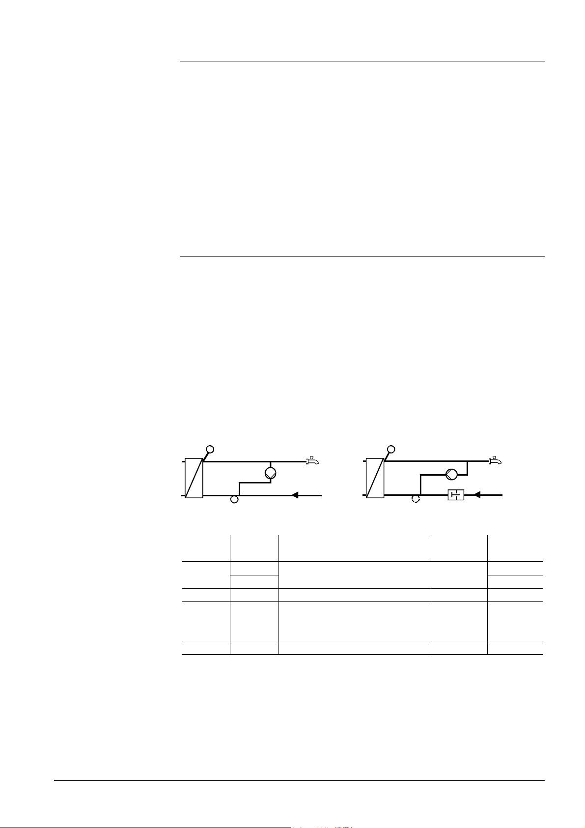
General
Caution
Mode of operation
16.3.5 Flow switch
If desired, a flow switch can be fitted in the heat exchanger’s cold water return. For this
purpose, the RVD240 provides digital input H5, which is to be configured on operating
line 55.
The flow switch improves the performance of the heat exchanger’s control. It indicates
to the control system when a demand for heat can be expected. When there is no flow,
it is possible to ensure that the d.h.w. delivered will not be too hot.
The use of a flow switch is especially recommended in the case of smaller plants (single-family houses, etc.).
Fault status supervision is not possible since short-circuits and open-circuits are permitted statuses.
Functions that are dependent on the flow switch are the adjustable load limit and the
child-proofing facility (refer to subsection 18.7.3).
16.3.6 Compensation of heat losses through control
Generally, heat losses due to d.h.w. consumption are always compensated for through
control.
In addition, when using a flow switch and a circulating pump, it is possible to configure
whether the control shall also be active outside periods of d.h.w. consumption, that is,
whether heat losses due to radiation, circulation, etc., shall be compensated for.
The configuration is to be made on operating line 54.
If a flow switch is used, the primary valve will temporarily be controlled by an opening
signal at the beginning of d.h.w. consumption, and by a closing signal at the end of
d.h.w. consumption.
To ensure that no excessive temperatures occur and the response of the control is fast,
an immersion sensor must be used in the case of configurations with no flow switch,
since that sensor immerses into the heat exchanger (e.g. type QAE21.93).
2383S32
B32
2383S31
B32
Plant without flow switch Plant with flow switch
Operating
line 55
≠4
Operating
line 54
0 No
1, 2, 3
Function Flow switch circulating
pump
Full compensation of heat losses
No
Yes
4 0, 1 No compensation of heat losses No No
4 2 Partial compensation of heat
Yes Yes
losses, maximum flow temperature
reduction by 20 % permitted
4 3 Full compensation of heat losses Yes Yes
Explanations relating to the settings on operating line 54:
Settings 0 and 1
There is no d.h.w. heating when no d.h.w. is consumed. This is true also when the circulating pump runs. Since heat losses are not compensated for, the d.h.w. temperature
will drop to the room temperature level eventually.
67/126
Siemens Building Technologies Basic documentation RVD240 CE1P2384en
HVAC Products 16 D.h.w. heating 27.05.2004
Page 68

Setting 2
Example
Setting 3
A temporary drop of the d.h.w. flow temperature is accepted. Heat losses are only partially compensated for; the flow temperature may drop by a maximum of 20 %. Subsequent heating up to the d.h.w. setpoint always takes a minimum of 5 minutes.
For the compensation of heat losses, the circulating pump must be released. If it is not
released, no control is provided independent of the d.h.w. flow temperature.
D.h.w. setpoint T
Cold water temperature T
Permissible reduction
Minimum d.h.w. flow temperature T
T
BWV
= T
– ∆T × (T
BWw
= 50 °C
BWw
= 10 °C (fixed value):
Nx
∆T = 20 %
= ?
BWV
– TNx ) = 50 – 0.2 (50 – 10) = 42 °C
BWw
The aim is to maintain the d.h.w. setpoint and all heat losses will be fully compensated
for. A circulating pump is used.
16.3.7 Cold water sensor
Cold water sensor B32 is fitted after the mixing point of cold water return and circulation
return. It should be located as close as possible to the mixing point. The sensor detects
temperature changes on the cold water side, which are then included in the flow temperature control. This improves the control performance considerably.
68/126
Siemens Building Technologies Basic documentation RVD240 CE1P2384en
HVAC Products 16 D.h.w. heating 27.05.2004
Page 69

17 Function block Extra legionella func-
tions
In d.h.w. systems with storage tanks, the legionella function ensures that legionella
viruses will not occur. This is accomplished by periodically raising the d.h.w. temperature in the storage tank.
17.1 Operating lines
Line Function, parameter Unit Factory
104 Legionella function 6 ---, 1…7, 1-7
105 Setpoint of legionella function °C 65 60…95
126 Time of legionella function hh:mm --:-- --:--,
127 Dwelling time at legionella setpoint min --- ---, 10…360
128 Circulating pump operation during legionella function 1 0 / 1
180 Maximum setpoint of return temperature with d.h.w. heating
at legionella setpoint °C ---
17.1.1 Legionella function
setting
If and when the legionella function shall be activated is to be set on operating line104.
The legionella function can be started when the d.h.w. temperature is at the nominal
setpoint (button for d.h.w. heating is lit and no holidays are active). The function will be
deactivated when the frost level is reached.
The legionella function can be aborted by pressing the button for d.h.w. heating.
Range
00:00…23.50
---,
0…140 °C
17.1.2 Setpoint
The legionella setpoint can be adjusted in the range from 60…95 °C (operating line
105). In the case of storage tanks with 2 sensors, the d.h.w. temperature must reach
the setpoint at both sensors.
17.1.3 Time
The legionella function is started at the set time. If no time has been set (operating line
126 =
--:--), the legionella function will be started with the first d.h.w. release at the nominal
setpoint.
If the legionella function cannot be performed at the set time because d.h.w. heating
has been deactivated (button for d.h.w. heating, holidays), it will be activated as soon
as d.h.w. heating is released again. In the case of d.h.w. heating with flow switch, the
legionella function will be activated at the set time, but the legionella viruses will only be
killed the next time d.h.w. is consumed.
17.1.4 Dwelling time
The legionella setpoint must be maintained for at least the set dwelling time.
If the lower storage tank temperature rises above the legionella setpoint minus 1 K, the
legionella function is considered completed and the dwelling has elapsed.
If the storage tank temperature falls by more than SD + 2 K (switching differential plus
2 K) below the legionella setpoint before the dwelling time has elapsed, the dwelling
time must again be completed.
If no dwelling time is set (operating line 127 =
---), the legionella function is completed
the moment the legionella setpoint is reached.
69/126
Siemens Building Technologies Basic documentation RVD240 CE1P2384en
HVAC Products 17 Function block Extra legionella functions 27.05.2004
Page 70

In the case of direct d.h.w. heating without circulating pump, the adjusted value is inactive (no dwelling time).
17.1.5 Operation of circulating pump
The circulating pump can be forced to run during the period of time the legionella function is active. This ensures that hot water also circulates through the plant’s hot water
distribution system. Entry (0 or 1) is made on operating line 128.
If the storage tank temperature exceeds the legionella setpoit minus 1 K, the circulating
pump will be forced to run.
If the storage tank temperature falls below the legionella setpoint by more than
SD + 2 K (switching differential plus 2 K), the circulating pump will no longer be activated.
17.1.6 Maximum limitation of the return temperature
Refer to section 26.2.3 “Maximum limitation in d.h.w. mode”.
17.2 Mode of operation
Conditions for activation of the legionella function:
• The storage tank temperature is acquired with 1 or 2 sensors (legionella function
cannot be provided when using thermostats)
• The legionella function has been parameterized (operating line 104)
• D.h.w. heating is switched on (button
• The holiday function is not active
If the criteria “Set day” and “Time” are met, the legionella function will be released. Release of the legionella function causes the d.h.w. temperature setpoint to be raised to
the level of the legionella setpoint and to forced charging. If d.h.w. heating is switched
off or the holiday function is active, the legionella function will be released. On completion of the overriding function, d.h.w. charging to the legionella setpoint will be triggered
since the legionella function continues to be released.
The behavior of the legionella function as a function of the d.h.w. temperature is as
follows:
T
BWx
is lit)
5 6
7
8
T
BWw
T
- SD
BWw
T
BWw
①
②
③
④
⑤
⑥
70/126
Siemens Building Technologies Basic documentation RVD240 CE1P2384en
HVAC Products 17 Function block Extra legionella functions 27.05.2004
BW
- SDBW - 2 K
ON
1
OFF
ON
2
OFF
ON
3
OFF
4
Circulating pump
Forced charging
Release of the legionella function
Start conditions for the legionella function met
Start dwelling time
Reset dwelling time
2381D07
t
Start dwelling time
⑦
Dwelling time has elapsed
⑧
D.h.w. temperature
T
BWx
T
D.h.w. temperature setpoint
BWw
SDBW Switching differential of d.h.w. heating
t Time
Page 71

If a maximum d.h.w. charging time has been set, it also acts here. If the legionella setpoint is not reached, the legionella function will be interrupted and resumed on completion of the maximum charging time.
The legionella setpoint will not be affected by the maximum of the d.h.w. temperature
setpoint.
71/126
Siemens Building Technologies Basic documentation RVD240 CE1P2384en
HVAC Products 17 Function block Extra legionella functions 27.05.2004
Page 72

18 Function block Valve actuator d.h.w.
18.1 Operating lines
Line Function, parameter Unit
111 Opening time actuator of d.h.w. circuit s 35 10...873
112 Closing time actuator of d.h.w. circuit s 35 10...873
113 P-band of d.h.w. control K 35.0 1.0...100.0
114 Integral action time of d.h.w. control s 35 10...873
115 Derivative action time of d.h.w. control s 16 0...255
116 Setpoint boost d.h.w. charging K 16 0...50
117 Maximum setpoint of d.h.w. temperature °C 65 20...95
118 Setpoint boost mixing valve / heat exchanger d.h.w. K 10 0...50
119 Reduced d.h.w. setpoint for storage tank sensor at the bottom K 5 0...20
120 Circulating pump for d.h.w. charging 0 0 / 1
124 Load limit for actuation of flow switch % 25 0...60
Factory
setting
Range
18.2 Mode of operation
This function block provides d.h.w. temperature control with a mixing valve or 2-port
valve. The sensor and the type of actuating device required depend on the type of
plant:
Plant type Sensor Regulating unit Location of sensor and regulating unit
1–3 B71 Valve Y5 Primary return of d.h.w. heat exchanger
2–2 B3 Mixing valve Y5
1–4, 1–8,
1–9, 4–x
B3 Valve Y5
D.h.w. flow (intermediate circuit)
18.3 Control process
If the flow temperature deviates from the setpoint, the 2-port or mixing valve is adjusted
in a stepwise fashion to compensate for the deviation (with plant type 1–3, this can also
be accomplished with 2-position control). The controller drives an electric or electrohydraulic actuator.
The ideal running time of the actuator is 10...35 seconds.
The actuator’s opening and closing times are separately adjustable, thus making certain that actuators with asymmetric running times can also be used.
To enhance the control performance, the derivative action time (D-part of PID control)
can be adjusted, in addition to the P-band and the integral action time.
If, with plant type 1–3, no return sensor B71 is used, the function block will operate as a
2-position controller. When there is a demand for heat, 2-port valve Y5 will be fully
opened; with no demand for heat, it is fully closed. This takes place independent of
whether or not maximum limitation of the d.h.w. return temperature is activated.
18.4 Setpoint boost
Setpoint boost ensures that the flow temperature required by the consumer to perform
its function (control) will be delivered by the heat source.
72/126
Siemens Building Technologies Basic documentation RVD240 CE1P2384en
HVAC Products 18 Function block Valve actuator d.h.w. 27.05.2004
Page 73

18.4.1 Charging boost
The charging boost for the d.h.w. setpoint can be set on operating line 116. This is the
difference between the heat demand to the heating medium (setpoint) and the setpoint
of the d.h.w. in the storage tank.
18.4.2 Flow temperature boost
The boost for the mixing valve or the heat exchanger in the d.h.w. circuit can be set on
operating line 118. In the case of direct d.h.w. heating via heat exchanger (plant types
x–4), the charging boost is also set on this operating line because the heat exchanger
is external.
18.5 Maximum setpoint of the d.h.w. temperature
On operating line 117, the maximum d.h.w. setpoint that can be set on operating line 4
is defined. Depending on the type of plant, the setting range is as follows:
Plant type Minimum setting value Maximum setting value
1–3, 1–9, 2–1,
2–2, 3–1, 4–9
1–4, 1–8, 2–6,
4–4, 4–8
Reduced setpoint (setting
on operating line 42)
Reduced setpoint (setting
on operating line 42)
Minimum selection from:
• Setting value on operating line 117
• Sum of setting values on operating
lines 116 and 176 (maximum limit
value of return temperature with
d.h.w. charging)
Setting value on operating line 117
In any case, the setting range is limited at a maximum of 100 °C.
18.6 D.h.w. charging with two storage tank
sensors
With the plant types using a d.h.w. storage tank, the storage tank temperature can be
acquired with one or 2 sensors (B31 and B32).
When using two storage tank sensors, the amount by which the setpoint of the colder
storage tank sensor is lower than that of the warmer sensor can be set on operating
line 119.
When 2 sensors are used, the switch-off criterion for d.h.w. charging is reached when
• the sensor with the higher temperature has attained the d.h.w. setpoint, and
• the sensor with the lower temperature has attained the reduced d.h.w. setpoint.
The ”reduced setpoint” for the sensor with the lower temperature allows the secondary
return temperature to be kept low until the end of d.h.w. charging, in spite of mixing in
the stratification tank.
The switching differential of the d.h.w. temperature still applies.
18.7 Adjustable load limit
18.7.1 Adjustment to the time of year
To enable the controller to also provide stable d.h.w. temperature control when connection conditions vary (summer / winter operation) it must adjust the running time. This
adjustment is made with the current maximum stroke.
73/126
Siemens Building Technologies Basic documentation RVD240 CE1P2384en
HVAC Products 18 Function block Valve actuator d.h.w. 27.05.2004
Page 74

Mode of operation
Calculation of the setting value
When the plant is started up, the assumption is made that the maximum stroke be 50 %.
If the controller opens the actuator by more than 50 %, the stroke model continually adjusts the current maximum stroke ”towards 100 %". At midnight, the current stroke is reduced by 1 %. If the plant is not in use for a longer period of time, the minimum is 20 %.
18.7.2 Load limit
The flow switch delivers fast information, independent of the d.h.w. flow sensor. This
ensures that the entire heat on the heat exchanger’s secondary side is exchanged before the control of the primary valve is passed to the d.h.w. control.
As soon as d.h.w. is consumed, the flow switch opens primary valve Y5 for a certain
period of time, independent of the flow temperature. This opening time can be set with
the load limit setting on operating line 124. The setting is to be made in % of the maximum stroke.
Normally, in summer operation, the valve opening required for 100 % load is about 80 %.
This percentage is called the design point and must be included in the calculations.
The load limit can be calculated according to the following formula:
Load limit =
heat exchanger volume
∅ d.h.w. consumption × opening time × design point
secondary
Example of calculating the load limit to be set for a heat exchanger with the following
characteristics:
Water content on the secondary side = 1.0 liter
Average d.h.w. consumption = 0.14 liters / second
Opening time of d.h.w. actuator = 35 seconds
Design point = 80 % (0.8)
Load limit =
0.14 × 35 × 0.8
1,0
× 100 = 25 %
This value is used as a guide value and can vary depending on the plant’s hydraulic
layout. It is recommended to start with the calculated load limit and then
• decrease the value if the d.h.w. flow temperature significantly overshoots after d.h.w.
consumption
• increase the value if the d.h.w. flow temperature significantly undershoots
After the load limit is reached, the control system will take on control of the actuator on
the primary side.
The end of d.h.w. consumption is also detected by the flow switch and actuator Y5 on
the primary side will be driven to the fully closed position.
18.7.3 Child-proofing
If the d.h.w. tap is repeatedly opened (e.g. by children playing with the tap), the childproofing function prevents the load limit function from being executed more often than
necessary, thus preventing excessive d.h.w. temperatures.
If, within a period of 10 seconds, the d.h.w. tap is opened more than twice, the controller will ensure d.h.w. heating without the support of the load limit function.
74/126
Siemens Building Technologies Basic documentation RVD240 CE1P2384en
HVAC Products 18 Function block Valve actuator d.h.w. 27.05.2004
Page 75

19 Function block Assignment of d.h.w.
19.1 Operating line
Line Function, parameter Unit Factory setting Range
125 Assignment of d.h.w. heating 0 0...2
19.2 Assignment of d.h.w. heating
Operating line 125 is used to select for which controllers in an LPB system the d.h.w. is
heated or, in other words, which heating circuits get their d.h.w. from the same source.
With plant types x–0, this setting is not required since they provide no d.h.w. heating.
Setting Explanation
0 The d.h.w. is only provided for the heating circuit associated with the own
controller.
The d.h.w. is only provided for the heating circuits of the controllers with
1
the same segment number that are connected to the data bus (LPB).
The d.h.w. is provided for all heating circuits of the controllers connected to
2
the data bus (LPB).
The setting is active only when setting 1 (according to the space heating switching program with forward shift) has been selected on operating line 101 (d.h.w. release).
75/126
Siemens Building Technologies Basic documentation RVD240 CE1P2384en
HVAC Products 19 Function block Assignment of d.h.w. 27.05.2004
Page 76

20 Function block LPB parameters
20.1 Operating lines
Line Function, parameter Unit
131 Device number for bus address 0 0...16
132 Segment number for bus address 0 0...14
133 Clock mode 0 0...3
134 Bus power supply, operating mode and status indication A 0 / 1 / A
135 Outside temperature source A A / 00.01...14.16
136 Gain of locking signal % 100 0...200
137 Response to uncritical locking signals from the data bus 1 0 / 1
Factory
setting
Range
20.2 LPB parameters
20.2.1 Addressing the devices
Each device connected to the data bus (LPB) requires an address. This address is
comprised of a device number (1...16, operating line 131) and a segment number
(0...14, operating line 132).
In an interconnected plant, each address may be assigned only once. If this is not observed, proper functioning of the entire plant cannot be ensured. In that case, a fault
status signal will be generated (error code 82).
If the controller is operated autonomously (with no bus), both the device number and
the segment number must be set to zero.
Since the device address is also associated with control processes, it is not possible to
permit all possible device addresses in all types of plant:
If an inadmissible address has been entered for the selected type of plant, a fault status
signal will appear (error code 140).
For detailed information about the addressing of devices, refer to Data Sheet N2030.
20.2.2 Source of time of day
Depending on the master clock, different sources for the time of day can be used. The
source must be entered on the controller on operating line 133, as a digit (0…3):
0 = autonomous clock in the RVD240
1 = time of day from the bus; clock (slave) with no remote readjustment
2 = time of day from the bus; clock (slave) with remote readjustment
3 = time of day on the bus; central clock (master)
The effect of the individual entries is as follows:
Input Effect Diagram
0 • The time of day on the controller can be
Adjustment
readjusted
• The controller's time of day is not
matched to the system time
1 • The time of day on the controller cannot
Controller time
Adjustment
System time
be readjusted
• The controller's time of day is automati-
cally and continually matched to the sys-
Controller time
System time
tem time
76/126
Siemens Building Technologies Basic documentation RVD240 CE1P2384en
HVAC Products 20 Function block LPB parameters 27.05.2004
Page 77

• The time of day on the controller can be
2
readjusted and, at the same time, readjusts the system time since the change
is adopted by the master
Controller time
Adjustment
System time
• The controller's time of day is neverthe-
less automatically and continually
matched to the system time
• The time of day on the controller can be
3
readjusted and, at the same time, readjusts the system time
• The controller time is used as a pre-
Controller time
Adjustment
System time
2522B12e
setting for the system
In each system, only one controller may be used as a master. If several controllers are
set as masters, a fault status signal will be delivered (error code 100).
20.2.3 Bus power supply
In interconnected plants with a maximum of 16 controllers, the bus power supply may
be decentralized, that is, power may be supplied via each connected device. If a plant
contains more than 16 devices, a central bus power supply is mandatory.
On each connected device, it is then necessary to set whether the data bus is powered
centrally or decentrally by each controller.
With the RVD240, this setting is to be made on operating line 134. The current setting
is shown on the left and the current bus power supply status on the right.
Display Automatic bus power supply on the controller Bus power supply
currently present
0 0
0 1
A 0
A 1
Bus power supply is central (no power supply via
controller)
On, decentral bus power supply by the controller
No
Yes
No
Yes
The word BUS appears on the display only when the bus address is valid and when
bus power supply is available. This means the display indicates whether or not data
traffic via the data bus is possible.
20.2.4 Outside temperature source
If, in interconnected plants, the outside temperature is adopted from the data bus, the
temperature source can be addressed either automatically or directly (operating line
135).
Addressing Display, entry Explanation
Automatically A ss.gg xx = segment number
gg = device number
Directly ss.gg To be entered is the address of the outside
temperature source
If the controller is operated autonomously (with no bus), there will be no display and no
entry can be made.
If the controller is used in an interconnected plant and if it has its own outside sensor, it
is not possible to enter an address (if an entry is made, the display shows OFF). In that
case, the controller always uses the outside temperature signal delivered by its own
sensor. The address displayed is its own.
For detailed information about addressing the outside temperature source, refer to Data
Sheet N2030.
77/126
Siemens Building Technologies Basic documentation RVD240 CE1P2384en
HVAC Products 20 Function block LPB parameters 27.05.2004
Page 78

21 Locking signals
21.1 Fundamentals
The following functions use locking signals and send them to the heat converters and
consumers:
• Minimum limitation of the boiler return temperature
• Protective boiler startup
• D.h.w. priority
With the heat exchanger and consumer controllers, it is possible to set on operating line
136 (gain of locking signal) to what degree they shall respond to a locking signal. This
gain of the locking signal is adjustable from 0 to 200 %.
For heat converters and consumers with 3-position control, following applies:
Setting operating line 136 Response
0 % Locking signals will be ignored
100 % Locking signals will be adopted 1-to-1
For consumers with 2-position control, following applies:
Setting operating line 136 Response
There are 2 types of locking signals:
• Uncritical locking signals
• Critical locking signals
The response of the consumers / heat converters depends on the type of locking signal.
200 % Locking signals will be adopted 2 times
0 % Locking signals will be ignored
>0 % Locking signals will be adopted 1-to-1
21.2 Critical locking signals
Critical locking signals are generated by the boiler controller with protective boiler
startup or during minimum limitation of the boiler return temperature, aimed at throttling
the consumers to get out of the crucial range more quickly.
If the boiler controller is in segment 0, the critical locking signal will sent to all heat converters and consumers in the entire bus system.
If the boiler controller is in segment 1…14, it will only send the locking signal to all heat
converters and consumers in its own segment.
• Heat converters and consumers with 3-position control reduce their control setpoint
depending on the magnitude of the locking signal and the setting "Gain of locking
signal". The pump will not be deactivated
• Consumers with 2-position control deactivate the pump at a defined locking signal
value if the setting "Gain of locking signal" >0 %. The switch-off point depends on the
setting "Gain of locking signal"
The RVD240 cannot generate critical locking signals since it is not a boiler controller.
Plant type x–4 is the only consumer that never responds to critical locking signals.
21.3 Uncritical locking signals
21.3.1 General
Uncritical locking signals are generated in connection with the d.h.w. priority (absolute
and shifting) and only act on the heating circuits. The following locking signals exist:
• "Controller-internal locking signals"
• "Locking signals from the data bus (LPB)"
78/126
Siemens Building Technologies Basic documentation RVD240 CE1P2384en
HVAC Products 21 Locking signals 27.05.2004
Page 79

For detailed information, refer to chapter 21.
All heat converters that lie in the supply chain of the d.h.w. demanding priority are not
affected by the uncritical locking signal.
Whether the controller shall respond to uncritical locking signal from the data bus can
be selected on operating line 137 (response to uncritical locking signals from the data
bus). The setting does not affect the response to controller-internal locking signals.
Setting operating line 137 Response
0 Uncritical locking signals from the data bus will be ignored
1 Uncritical locking signals from the data bus will be adopted
21.3.2 Controller-internal uncritical locking signals
Controller-internal uncritical locking signals always throttle the heating circuits. With
plant type 4–x, the heat converter parallel to d.h.w. will be affected.
21.3.3 Uncritical locking signals from the data bus
Uncritical locking signals from the data bus throttle the heat converters and the heating
circuits.
79/126
Siemens Building Technologies Basic documentation RVD240 CE1P2384en
HVAC Products 21 Locking signals 27.05.2004
Page 80

22 Function block Device functions
22.1 Operating lines
Line Function, parameter Unit Factory setting Range
141 Actuator pulse lock 1 0 / 1
142 Frost protection for the plant 1 0 / 1
143 Flow alarm h --:-- --:-- / 0:10...10:00
144 Winter- / summertime changeover 25.03. 01.01. ... 31.12.
145 Summer- / wintertime changeover 25.10. 01.01. ... 31.12.
146 Pump kick 1 0 / 1
22.2 Actuator pulse lock
This function acts on all 3-position actuators controlled by the RVD240.
If, during a total period of time that equals 5 times the running time, an actuator has
received opening or closing pulses, additional closing pulses in the same direction will
be suppressed by the controller.
For safety reasons, the controller delivers a one-minute closing pulse in the appropriate
direction to the controller at 10-minute intervals.
A pulse in the opposite direction negates the pulse lock.
This function acts on all actuators used in the plant and is intended to reduce the wear
on the relay contacts and to extend the life of the actuators. It can be deactivated on
operating line 141 (entry of 0).
22.3 Frost protection for the plant
22.3.1 Principle
Frost protection for the plant protects both heating circuits against freeze-ups by activating the respective heating circuit pump. For this purpose, both the controller and the
heat source must be ready to operate (mains voltage present).
Frost protection for the plant is possible with or without outside sensor. The switching
differential is 1 K (fixed value).
Frost protection is always active, also
• when the control is switched off (standby )
• during quick setback
• during OFF periods by the ECO function
If required, frost protection for the plant can be deactivated (setting on operating line
142 = 0).
In addition to frost protection for the plant through activation of the heating circuit pump,
frost protection for the heating circuit flow is active.
22.3.2 Mode of operation with outside sensor
Frost protection for the plant operates in 2 stages:
1. If the outside temperature falls below 1.5 °C, the heating circuit pump will be acti-
vated for 10 minutes at 6-hour intervals.
2. If the outside temperature falls below –5 °C, the heating circuit pump will be acti-
vated and runs continuously.
When active, the respective frost protection stage will be switched off when the outside
temperature has exceeded the limit value by 1 K.
80/126
Siemens Building Technologies Basic documentation RVD240 CE1P2384en
HVAC Products 22 Function block Device functions 27.05.2004
Page 81

22.3.3 Mode of operation without outside sensor
Frost protection for the plant operates in 2 stages:
1. If the flow temperature (sensor B1) falls below 10 °C, the heating circuit pump will
be activated for 10 minutes at 6-hour intervals.
2. If the flow temperature falls below 5 °C, the heating circuit pump will be activated
and runs continually.
When active, the respective frost protection stage will be switched off when the flow
temperature has exceeded the limit value by 1 K.
22.3.4 Frost protection for the heating circuit flow
In addition to frost protection for the plant through activation of the heating circuit pump,
frost protection acts separately on both heating circuits. This frost protection is single
stage and will be activated when the heating circuit flow drops below 5 °C. The switching differential is 2 K; switching off takes place at >7 °C. Frost protection for the heating
circuit flow generates a demand for heat (flow temperature setpoint) of 10 °C and, after
reaching the switch-off criterion, will be active for a minimum of 5 minutes.
22.4 Flow alarm
22.4.1 Heating circuit and d.h.w. circuit with storage tanks
The purpose of this function is to detect bottlenecks in the heat supply of the district
heat network.
The flow alarm triggers a fault status signal when the flow temperature in
• one or both heating circuits
• the common flow
• the d.h.w. circuit
does not reach the setpoint band (setpoint ± switching differential of 3 °C) within a defined period of time when there is demand for heat. This period of time can be set on
operating line 143.
The flow alarm becomes inactive as soon as the setpoint band is reached.
The flow alarm appears on the display as ERROR and, on operating line 50, with an
error code.
The correlation between sensor, plant type and error code in the heating circuit control
systems is the following:
Heating circuit
control
1–x 2–x 3–x 4–x
Sensor / controlling element per plant type
Common flow B1/Y1 B1/Y1 B1/Y1 120
Heating circuit 1: B1/Y1 B12/Y5 121
Heating circuit 2: B12/Y7 2–0, 2–1, 2–6: B12/Y1
B3/Y7 B12/Y7 122
2–2: B12/Y7
The following table applies to d.h.w. heating:
Plant type Sensor / controlling element Error code
1–8, 1–9, 2–2, 4–8, 4–9 B3 / Y5 123
2–6 B3 / no mixing valve 123
Error
number
Plant type 1–3 has no flow alarm since there is no flow sensor in the d.h.w. circuit.
81/126
Siemens Building Technologies Basic documentation RVD240 CE1P2384en
HVAC Products 22 Function block Device functions 27.05.2004
Page 82

Caution
Flow alarm:
T
V
wx
t
A
t Time TV Flow temperature
t1 Start of ERROR display w Setpoint
t2 End of ERROR display x Actual value
tA Waiting time (set on operating line 143) Y Setpoint band (setpoint ± 1 K)
• At t
, an error message is triggered; during the period of time tA (set on operating line
1
y
t
A
t
A
ERROR
t
1
t
2
2524D05
t
143), the actual value stayed below the setpoint band y
• At t
, the error message reset; the actual value x has reached the setpoint band y
2
The flow alarm can be deactivated by entering --:-- .
When the flow alarm function is activated, any flow or differential temperature sensors
(if present) may not be used for display since their signals are used for evaluation.
Overtemperature
supervision
22.4.2 Direct d.h.w. heating via heat exchanger
With plant types x–4, this function is required to detect faults on the primary valve and
primary actuator, faults that may pose a risk to the end-user. Hence, this function has
not been introduced to monitor the performance of d.h.w. control but to monitor the
temperature!
The function will be activated when the current d.h.w. setpoint is exceeded by 10 K for
a period of 20 seconds.
The flow alarm appears on the display as ERROR and, on operating line 50, with error
code 123.
When no circulating pump is present (setting 0 on operating line 54), relay Q3 will be
energized; it can thus be used to switch on a monitoring device, for example.
Flow alarm for overtemperature supervision:
T
V
w
x
t
B
ERROR
2383D05
t
t Time TVFlow temperature
t1 Start of ERROR display w Setpoint
t2 End of ERROR display x Actual value
tB Waiting time (20 s) "Forbidden” range
t
1
2
t
82/126
Siemens Building Technologies Basic documentation RVD240 CE1P2384en
HVAC Products 22 Function block Device functions 27.05.2004
Page 83

Undertemperature
supervision
With plant types x–4, this function is required to detect bottlenecks in the heat supply
from the district heat network. Undertemperature supervision triggers an error message
when, for a defined period of time during a demand for heat, the flow temperature falls
below the flow temperature setpoint by more than 10 K. This period of time can be set
on operating line 143. The flow alarm becomes inactive as soon as the limit is exceeded again.
Flow alarm for undertemperature supervision:
T
V
t
t
1
2
t
A
ERROR
w
x
2383D07
t
t Time TV Flow temperature
t1 Start of ERROR display w Setpoint
t2 End of ERROR display x Actual value
tA Waiting time (set on operating line 143) "Forbidden” range
The flow alarm appears on the display as ERROR and, on operating line 50, with error
code 123.
The flow alarm can be deactivated by entering --:-- .
Example
22.5 Winter- / summertime changeover
The change from wintertime to summertime, and vice versa, is made automatically. If
international regulations change, the relevant changeover dates can be entered on
operating lines 144 and 145. The entry to be made is the earliest possible changeover
date. The weekday on which changeover occurs is always a Sunday.
If the start of summertime is given as "The last Sunday in March", the earliest possible
changeover date is March 25. The date to be entered on operating line 144 is then
25.03.
If no summer- / wintertime changeover is required, the 2 dates are to be set so that
they coincide.
83/126
Siemens Building Technologies Basic documentation RVD240 CE1P2384en
HVAC Products 22 Function block Device functions 27.05.2004
Page 84

23 Function block M-bus parameter
23.1 Operating lines
Line Function, parameter Unit
151 M-bus primary address 0 0...250
152 M-bus secondary address Display function
153 Baud rate Baud 2400 300 / 2400
154 Passing on the M-bus power control signals (Load Management) 0 0...2
155 M-bus power control in the heating circuit (Load Management) Display function
Factory
setting
Range
23.2 General
The M-bus to EN 1434-3 serves for reading setpoints and actual values. In addition,
individual end-user values can be written by the management system.
The remote setting of controller parameters via M-bus is not possible.
23.3 Addressing and identification
Addressing on the M-bus consists of a primary and a secondary address. The default
primary address is 0; the serial number is to be entered as the secondary address.
Both parts of the address can be changed via M-bus, the primary address on operating
line 151.
23.4 Baud rate
The Baud rate can be polled on operating line 153. For systems without automatic dispatch of the Baud rate to the slaves, the rate can be set.
23.5 Load management
23.5.1 Load management of d.h.w.
With load management of d.h.w., other d.h.w. setpoints can be imposed on the controller via M-bus. This makes sense when there is too much or too little heat available at
the district heat connection.
When entering 0...4 on the M-bus master, the controller will respond as follows:
Input Response of controller
0 Load management deactivated
1 Corresponds to manual charging by pressing button
2 Corresponds to manual charging by pressing button , but d.h.w. is heated
up to the legionella setpoint
3 The current d.h.w. setpoint is the nominal setpoint minus the switching differ-
ential. The switching differential acts from the new setpoint
4 The current d.h.w. setpoint is the d.h.w. setpoint for frost protection
5 The current d.h.w. setpoint is the reduced d.h.w. setpoint
23.5.2 Load management of the heating system
Load management of the heating system uses internal locking signals or acts on the
demand for heat (refer to the relevant sections) in order to throttle or push the demand.
84/126
Siemens Building Technologies Basic documentation RVD240 CE1P2384en
HVAC Products 23 Function block M-bus parameter 27.05.2004
Page 85

Caution
The validity of the demand for heat will not be influenced. The compensating variable
will not be influenced either since load management is a short-term intervention.
23.5.3 Resetting the load control signals
The controller clears all load control commands 2 hours after their activation if they
have not already been reset via M-bus. In general, a load control command will not be
reset when a setpoint is reached; this means that the command is not only executed
once, but is valid during the entire duration of the intervention.
23.5.4 Use on the LPB
On operating line 154, it is possible to define whether the load control signals received
via M-bus shall be used only locally or, additionally, shall be passed on via LPB in the
segment or in the entire interconnected system.
The numbers on the display have the following meaning:
Input Use
0 Only locally
1 In the same LPB segment
2 In the entire LPB system
• When the signals are delivered in the LPB segment, no other device in that segment
may be connected to the M-bus!
• When the signals are delivered throughout the LPB system, no other device in the
entire LPB system may be connected to the M-bus!
23.5.5 Resolution of M-bus signals
Signal Resolution
Water temperatures 1.0 °C
Air temperatures 0.1 °C
Voltage at DC 0...10 V input 0.1 V
85/126
Siemens Building Technologies Basic documentation RVD240 CE1P2384en
HVAC Products 23 Function block M-bus parameter 27.05.2004
Page 86

24 Function block PPS parameter
This function block defines the devices and the actions on the PPS. The RVD240 is the
master; the connected devices (max. 2) are the slaves.
24.1 Operating lines
Line Function, parameter Unit Factory setting Range
156 Active slaves on the PPS Display function
158 Actions with 1 room unit and 2 heating circuits 0 0...5
24.2 Suitable devices
The following devices can be connected to the PPS terminals:
• Room unit QAW50 or QAW50.03 (addressable)
• Room unit QAW70 (addressable from software version 1.20)
• Room sensor QAA10 (not addressable)
Each of these units has an address. It can be called up on operating line 156 using
buttons
Displayed address Room unit
The example given in the above table uses address 1.
For each of the 2 heating circuits, a room unit can be connected to the RVD240. One of
the 2 units must be addressable however. The combination of 2 nonaddressable units
(e.g. QAW50 or QAA10) is not permitted.
This means:
• The first room unit can be a QAA10, QAW50, QAW50.03 or QAW70
• The second room unit must then be a QAW50.03 or QAW70, addressed with 2
and :
1 82 Room unit QAW50 or QAW50.03
1 83 Room unit QAW70
1 90 Room temperature sensor QAA10
--- --- No device present
24.3 Impacts of a room unit on the heating circuits
If only one room unit is connected to the PPS, its actions on the 2 heating circuits must
be defined:
Room unit function
0 1 2 3 4 5
The actual room temperature of the
1 1 2 2 1 and 2 1 and 2
room unit acts on the flow temperature control in heating circuit(s) ...
Switching program and room unit
1 1 2 2 1 1
settings act on heating circuit(s) ...
Display of flow temperature in the
1 1 2 2 1 1
heating circuit ...
Operating mode, operation level and
1 1 and 2 2 1 and 2 1 1 and 2
holiday program of the room unit act
on the heating circuit(s) ...
86/126
Siemens Building Technologies Basic documentation RVD240 CE1P2384en
HVAC Products 24 Function block PPS parameter 27.05.2004
Setting
Page 87

25 Function block Test and display
25.1 Operating lines
Line Function, parameter Unit Factory setting Range
161 Sensor test 0 0...11
162 Display of setpoint 0 0...11
163 Relay test 0 0...10
164 Speed of speed-controlled pump Display function
165 Display of digital inputs Display function
169 Display of active limitations Display function
170 Software version Display function
25.2 Sensor test
The sensor test includes the temperature acquired with each sensor and the voltage
present at the analog input. Interrogation is made with the setting buttons
To identify the acquired variable, a code is used.
The numbers on the display have the following meaning:
--.- = open-circuit / no sensor connected to input B9
oo.o = short-circuit at input B9
--- = open-circuit / no sensor present
ooo = short-circuit at the other inputs
Code Input Acquired variable, measured value
0 B9 Weather (outside temperature)
1 B1 Flow temperature heating circuit 1 or heat converter
2 B3 D.h.w. flow temperature
3 A6 Room unit heating circuit 1
4 A6 Room unit heating circuit 2
5 B7 Return temperature
6 B71 Return temperature
7 B72 Return temperature
8 B31 Storage tank temperature
9 B32 Storage tank temperature
10 B12 Flow temperature heating circuit 2
11 U1 DC 0...10 V / 0…130 °C
and .
25.3 Setpoint test
The setpoint test includes the display of the setpoint assigned to each sensor. Interrogation is made with the setting buttons
code is used.
--- means: No setpoint available
Code Input Setpoint of the …
0 B9 composite outside temperature
1 B1 flow temperature heating circuit 1 or heat converter
2 B3 d.h.w. flow temperature
3 A6 room unit heating circuit 1
4 A6 room unit heating circuit 2
5 B7 return temperature
6 B71 return temperature
7 B72 return temperature
8 B31 storage tank temperature
Siemens Building Technologies Basic documentation RVD240 CE1P2384en
HVAC Products 25 Function block Test and display 27.05.2004
and . To identify the acquired variable, a
87/126
Page 88

Caution
9 B32 storage tank temperature
10 B12 flow temperature heating circuit 2
11 – --- (not available)
Using the line selection buttons and , it is possible to switch from the sensor test
to the setpoint test, and vice versa; in that case, the selected code is maintained.
25.4 Relay test
The relay test is made to manually energize each relay contained in the RVD240 in
order to check its status. The relays are energized by pressing the setting buttons
and
.
Each relay is assigned a code:
Code Response or current state
0 Normal operation (no test)
1 All relays deenergized
2 Relay at terminal Y1 energized
3 Relay at terminal Y2 energized
4 Relay at terminal Q1 energized
5 Relay at terminal Q3 energized
6 Relay at terminal Y5 energized
7 Relay at terminal Y6 energized
8 Relay at terminal Q2 energized
9 Relay at terminal Y7 / Q4 energized
10 Relay at terminal Y8 / K6 energized
Before making the relay test, always close the main valve!
The relay test is terminated as follows:
• Select another operating line, or
• Press any of the operating mode buttons, or
• Switch to manual operation, or
• Automatically after 8 minutes
25.5 Display of the pump speed
The display is made on operating line 164; the speed of the pump selected on operating line 57 is given as a percentage of the nominal speed.
25.6 Display of the digital inputs
On operating line 165, information about the digital input variables is available. Interrogation is made with the setting buttons
is used.
Contact H5
At input H5, it is possible to receive pulses. Such pulses can be, for instance:
• Heat demand signal
• Signals from an alarm contact
• Pulses from the flow switch
The current state of the contact can be queried:
0 = contact open
1 = contact closed
The display shows H5 and 0 or 1
88/126
Siemens Building Technologies Basic documentation RVD240 CE1P2384en
HVAC Products 25 Function block Test and display 27.05.2004
and . For identification, the display format
Page 89

Pulses
If pulses are received at H5 (e.g. pulses for limiting the volumetric flow through heat
meters), the number of pulses received per minute will be displayed.
Only entire pulses can be displayed. The display shows pulses/min; the measurement
range is 0...2250 pulses/min.
The display shows H5 and the measured value.
Radio clock receiver
If a radio clock receiver is connected to the data bus (LPB), the RVD240 can receive
the radio signals via data bus. On operating line 165, it is possible to see how much
time has elapsed (hh:mm) since the radio clock receiver received the last correct time
telegram.
The display shows r c l (Radio Clock) and hh:mm. If no valid value is available, the
display cannot be selected. The reason can be one of the following:
• No radio clock receiver connected
• Controller has no data bus address
• Connection interrupted
25.7 Limitations
Active limitations are displayed on operating line 169. Interrogation is made with the
setting buttons
tion symbol.
Code Symbol Type of
1
2
3
4
5
6
7
8
9
10
11
12
13
14
15
16
17
18
19
20
21
22
23
24
25
26
27
* For suppressing hydraulic creep
** According to the setting made on operating line 56 (action of pulse input on the heating circuits)
and . Each limitation is assigned a code and the respective limita-
Limited variable
limitation
Maximum Volumetric flow or output, common flow
Maximum Common primary return
Maximum Temperature differential (DRT), common flow
Maximum Common secondary flow
Maximum Volumetric flow or output, heating circuits**
Maximum Primary return heating circuit 1
Maximum Secondary return heating circuit 1
Maximum Temperature differential (DRT) heating circuit 1
Maximum Secondary flow heating circuit 1
Maximum Room temperature heating circuit 1
Maximum Flow temperature rise heating circuit 1
Maximum Primary return heating circuit 2
Maximum Secondary return heating circuit 2
Maximum Temperature differential (DRT) heating circuit 2
Maximum Secondary flow heating circuit 2
Maximum Room temperature heating circuit 2
Maximum Flow temperature rise heating circuit 2
Maximum Primary return d.h.w.
Maximum Secondary return d.h.w.
Minimum Common flow primary side*
Minimum Common secondary flow
Minimum Flow heating circuit 1*
Minimum Secondary flow heating circuit 1
Minimum Reduced room temperature setpoint heating circuit 1
Minimum Flow heating circuit 2*
Minimum Secondary flow heating circuit 2
Minimum Reduced room temperature setpoint heating circuit 2
89/126
Siemens Building Technologies Basic documentation RVD240 CE1P2384en
HVAC Products 25 Function block Test and display 27.05.2004
Page 90

In general: The maximum limitation functions will be activated when the respective demand for temperature (not the actual value!) exceeds the limit value.
25.8 Software version
The software version is displayed on operating line 170. It is important for service staff
when making fault diagnoses.
90/126
Siemens Building Technologies Basic documentation RVD240 CE1P2384en
HVAC Products 25 Function block Test and display 27.05.2004
Page 91

26 Function block DRT and maximum
limitation of the return temperature
26.1 Operating lines
Note
Line Function, parameter Unit
171 Maximum limitation of primary return temperature heating circuits 0 0 / 1
172 Upper constant value, maximum limitation of the primary return
temperature
173 Slope, maximum limitation of the primary return temperature 7 0...40
174 Start of compensation (point of inflection), maximum limitation of the
primary return temperature
175 Lower constant value, maximum limitation of the primary return
temperature °C 50 0...variable
176 Maximum setpoint of the return temperature with d.h.w. heating °C --- --- / 0...140
177 Maximum limitation of the secondary return temperature, reduction
to the primary limit value °C --- --- / 0...50
178 Integral action time of the primary return temperature limitations min 30 0...60
179 Limit value of the maximum limitation of the temperature differential
180 Max. setpoint of the return temperature during d.h.w. heating on
legionella setpoint °C --- --- / 0…140
Factory
setting
°C 70
°C 10 –50...+50
K --.-
Range
Vari-
able...140
--.- /
0.5...50.0
This function block contains all parameters of the district heat network. Since many
district heat utilities demand locking of the settings, they are arranged on the locking
function level.
The following function blocks also belong to the locking function level. It includes all
operating lines from 171 through 196. This level can only be accessed with a code.
Also refer to subsection 31.1.6 "Setting levels and access rights".
In addition, locking on the hardware side is possible (operating line 196).
26.2 Maximum limitation of the primary return
temperature
26.2.1 General
The primary return temperature uses maximum limitation to
• ensure that too hot water will not be fed back to the district heat network
• minimize the pumping power of the district heat utility
• comply with the regulations of the utility (connection requirements)
Maximum limitation of the return temperature measures the return temperature on the
primary side and throttles the primary two-port valve if the limit value is exceeded.
Maximum limitation acts separately on both heating circuits and on the d.h.w. circuit.
The limit values and basic settings made on operating lines 172 through 178 apply to
both heating circuits, but the control operates independently.
With the types of plant that use a common flow (2–x and 3–x), the valid limit value is
controlled by the demand for heat of the heating circuits and of the d.h.w. circuit. When
both the heating circuits and the d.h.w. circuit call for heat, the higher of the limit values
applies.
Maximum limitation of the primary return temperature has priority over minimum limitation of the flow temperature in the heating circuit.
For primary temperatures exceeding 130 °C, a Pt 500 temperature sensor can be used.
91/126
Siemens Building Technologies Basic documentation RVD240 CE1P2384en
HVAC Products 26 Function block DRT and maximum limitation of the return temperature 27.05.2004
Page 92

26.2.2 Maximum limitation in heating mode
The limit value for maximum limitation in heating mode is generated from the following
variables:
• Function can be activated or deactivated for each heating circuit (selection on oper-
ating line 171)
• Upper constant value (setting on operating line 172)
• Lower constant value (setting on operating line 175)
• Slope (setting on operating line 173)
• Start of compensation (setting on operating line 174)
The current limit value can be determined as follows:
• If the outside temperature is higher than or equal to the value set for the start of
compensation (setting on operating line 174), the current limit value is the constant
value entered on operating line 175
• If the outside temperature is lower than the value set for the start of compensation,
the current limit value is calculated according to the following formula:
T
= T
L
L constant min
However, the current limit value T
T
PR
90
80
70
T
60
50
40
30
20
30
T
A
s Slope (operating line 173)
TA Actual outside temperature
T
Upper constant value (operating line 172)
L constant
T
Lower constant value (operating line 175)
L constant
Start of compensation (operating line 174)
T
L start
T
Primary return temperature
PR
L constant min
20
+ [ ( T
– TA ) × s × 0.1 ]
L start
T
L start
10 0
cannot be higher than the upper limit value.
L
T
L constant max
s
2383D01
-10
Limitation operates according to the selected characteristic:
• When the outside temperature falls, the return temperature will initially be limited to
the lower constant value
• If the outside temperature continues to fall, it will reach the selected starting point for
shifting compensation. From this point, the limit value will be raised as the outside
temperature falls. The slope of this section of the characteristic can be adjusted.
The setting range is 0...40; the effective value is 10 times smaller
• If the outside temperature falls further, the return temperature will be limited to the
upper constant value
26.2.3 Maximum limitation in d.h.w. mode
In contrast to maximum limitation in heating mode, maximum limitation of the primary
return temperature in d.h.w. mode uses a constant value. It is to be set on operating
line 176.
In order to reach the required anti-legionella temperature in the storage tank, a specific
maximum return temperature setpoint is used during the time the legionella function is
92/126
Siemens Building Technologies Basic documentation RVD240 CE1P2384en
HVAC Products 26 Function block DRT and maximum limitation of the return temperature 27.05.2004
Page 93

Example
active. If that setpoint is set inactive (operating line 180 = ---), there will be no maximum
limitation of the return temperature during the time the legionella function is active.
When both the heating and the d.h.w. circuit call for heat and maximum limitation of the
return temperature acts on both circuits, the higher of the two limit values applies.
If, with plant type 1–3, maximum limitation of the return temperature is deactivated (entry ---), the d.h.w. temperature will be controlled according to the return temperature
acquired with sensor B71 because there is no sensor in the d.h.w. flow. The controlled
setpoint is the sum of the current d.h.w. setpoint plus the charging boost (operating
line 116).
The current d.h.w. setpoint is generated internally and can be visualized as follows:
Select operating line 26 and press
.
26.3 Maximum limitation of the secondary return
temperature
The secondary return temperature of both the heating and the d.h.w. circuit can be
limited at a maximum, depending on the type of plant. The limit value is to be entered
on operating line 177 as a reduction to the current limit value of the maximum limitation
of the primary return temperature.
This function can become active only when the respective maximum limitation of the
primary return temperature (heating circuits or d.h.w.) is switched on. Maximum limitation of the primary return temperature can be deactivated on operating line 171 for the
heating circuit return (separately for each heating circuit), and on operating line 176 for
the d.h.w. return.
With plant type no. 2–2, the parameters are selected as follows:
Operating line 171 = 1 Maximum limitation of return temperature heating circuit
2 ON
Operating line 172 = 70 °C Upper constant value
Operating line 173 = 7 Slope
Operating line 174 = 10 °C Start of compensation at an outside temperature of
10 °C
Operating line 175 = 50 °C Lower constant value
Operating line 176 = 55 °C Maximum limitation of the return temperature in the
d.h.w. circuit
Operating line 177 = 5 °C Reduction on the secondary side
When the outside temperature changes, the maximum limitations will change also:
Outside temperature
Primary side Secondary side Primary side Secondary side
15 °C 50 °C (operating
line 175)
–5 °C* 60.5 °C** 55.5 °C
–20 °C 70 °C (operating
* With shifting compensation
** Equation according to subsection 26.2.2 “Maximum limitation in heating mode
line 172)
Heating circuit 1 D.h.w. circuit
45 °C (operating
line 175...177)
55 °C (operating line
50 °C (operating
line 176...177)
176)
65 °C (operating
line 172...177)
93/126
Siemens Building Technologies Basic documentation RVD240 CE1P2384en
HVAC Products 26 Function block DRT and maximum limitation of the return temperature 27.05.2004
Page 94

26.4 Maximum limitation of the temperature
differential (DRT function)
26.4.1 Mode of operation
With the types of plant that have sensor B71 fitted in the secondary return of the heating circuit or in the secondary return of the heat converter, maximum limitation of the
temperature differential (DRT, difference of primary and secondary return temperature)
can be provided. With plant type 1–0, it is also possible to monitor the temperature differential of heating circuit 2 using sensor B3.
If the differential of the two return temperatures exceeds the adjusted maximum limit
value, 2-port valve Y1 in the primary circuit will be throttled.
26.4.2 Purpose
Maximum limitation of the temperature differential generally ensures that a smaller
amount of heat will be drawn from the network or that the volumetric flow will be throttled when heat is demanded for the first time in the morning when the pipes have not
yet reached their normal operating temperature (prevention of idle heat and no unnecessary supply of heat back to the network).
In addition, maximum limitation of the temperature differential
• acts as a dynamic limitation of the return temperature
• shaves peak loads
Impact of maximum limitation of the return temperature differential:
V
VP [%]
DRT
OFF
S
DRT
on
100
90
80
70
60
50
40
30
20
10
0
2522D11
t
DRTON With active maximum limitation of the temperature differential
DRT
Without maximum limitation of the temperature differential
OFF
t Time
VS Volume saved
Volumetric flow on the primary side
The temperature differential of the return temperature is usually 2...5 °C and depends
on the type of heat exchanger. Maximum limitation of the temperature differential can
be deactivated on operating line 179 (entry of --.-).
Maximum limitation of the return temperature differential has priority over minimum
limitation of the flow temperature in the heating circuit.
During d.h.w. heating cycles, maximum limitation of the temperature differential is deactivated with all types of plant.
26.5 Integral action time of the limitation functions
With the maximum limitations of the return temperature, the integral action time determines the rate at which the flow temperature setpoint will be reduced.
• Short integral action times lead to faster reductions
• Long integral action times lead to slower reductions
With this setting (on operating line 178), the effect of the limitation function can be
matched to the type of plant.
94/126
Siemens Building Technologies Basic documentation RVD240 CE1P2384en
HVAC Products 26 Function block DRT and maximum limitation of the return temperature 27.05.2004
Page 95

27 Function block Various functions
27.1 Operating lines
Note
Line Function, parameter Unit
181 Limitation function at contact H5 1 1 / 2
182 Limit value of the volumetric flow or power limitation Imp/min 75 5...1500
183 Integral action time of the limitation function at contact H5 min 60 0...240
188 Locking time after the minimum limitation for the suppression of
hydraulic creep
189 Start of compensation (point of inflection), increase of the re-
duced room temperature setpoint
190 Slope, increase of the reduced room temperature setpoint 0 0...10
191 Forced charging at the beginning of release phase 1 1 0 / 1
192 Cooling down protection primary flow min --- --- / 3...255
Factory
setting
min 6 --- / 1...20
°C 5 –50...+50
Range
Function ”Forced charging at the beginning of release phase 1” on operating line
191 is only possible with d.h.w. heating with a storage tank and is described there (refer
to section 16.1 "D.h.w. heating with storage tanks ").
Function ”Cooling down protection primary flow” on operating line 192 is only available with direct d.h.w. heating via heat exchanger and is described there (refer to section 16.3 "Direct d.h.w. heating ").
27.2 Limitation function at contact H5
Input H5 at the RVD240 can be configured for the reception of energy and / or volumetric flow pulses from heat meters (entry on operating line 55 must be 1; in addition, the
way the limit function shall act on the heating circuits must be configured on operating
line 56). These pulses activate a limit function in the controller.
The kind of limitation can be selected on operating line 181:
Setting Type of pulse Function
1
Energy or volumetric flow
pulses
2
Energy and / or volumetric
flow pulses
The limit value is to be set on operating line 182. When the current number of pulses
reaches the set limit value or 100 % load, actuating device Y1 (2-port valve in the primary return) will be throttled. The action is always limited to the primary side of the
plant.
To enhance the control performance, the integral action time of the limitation function
can be set on operating line 183. It applies to both the maximum limitation with an adjustable limit value and to that with a fixed value. The setting value determines the rate
at which the flow temperature setpoint will be reduced:
• Short integral action times lead to faster reductions
• Long integral action times lead to slower reductions
With this setting, the effect of the limitation function can be matched to the type of plant.
When, with setting 2, no more pulses are received during a period of 20 seconds, error
code 180 will be generated on operating line 50 (connection to heat meter disrupted)
because the minimum pulse rate is 5 pulses/min.
Maximum limitation with an adjustable limit
value
Maximum limitation at a fixed value of
75 pulses/min (corresponding to 100 % load)
95/126
Siemens Building Technologies Basic documentation RVD240 CE1P2384en
HVAC Products 27 Function block Various functions 27.05.2004
Page 96

27.3 Suppression of hydraulic creep
27.3.1 Mode of operation
To avoid measurement errors in connection with heat metering due to extremely small
flow rates, the flow through the two-port valve in the primary return can be limited to a
minimum (Y
cannot be acquired and billed.
If the valve’s stroke reaches the minimum limit value, the valve will be fully closed and
then remains closed until the closing time has elapsed.
The first opening pulse delivered by the control after completion of the closing time will
reopen the valve and the control resumes normal operation.
What must always be set is the closing time. This is made on operating line 188, separately for each heating circuit; there, the function can also be deactivated by entering --- .
The suppression of hydraulic creep always acts on regulating unit Y1 in the primary return.
If suppression of hydraulic creep is active, the display shows . It is given priority over all
other limitations and acts on the types of plant with a common flow or with a precontrolled flow (plant types 2–x and 3–x), also during d.h.w. heating.
There is no suppression of hydraulic creep in the d.h.w. circuit connected to the primary
side.
function). This ensures that consumers will not be able to draw heat that
min
27.3.2 Mode of operation
The stroke corresponding to the minimum volumetric flow is acquired by an auxiliary
switch fitted in the actuator and is then delivered to the controller. The auxiliary switch
is connected to terminals B7–M. When the valve reaches the minimum limit value, the
auxiliary switch will close. When B7–M closes, the valve will be shut and the closing
time starts.
If the link is maintained although the controller delivers opening pulses of 20 % of the
running time, or if the flow temperature setpoint exceeds the setpoint by more than
10 K, the function will deactivate itself until the auxiliary switch in the actuator opens
again.
27.4 Raising the reduced room temperature
setpoint
The reduced room temperature setpoint can be raised as a function of the falling outside temperature. This ensures that
• the change from the reduced setpoint to the nominal setpoint will not be too great
when outside temperatures are very low
• there will be no extreme peak loads during the heating up phase.
What can be set is a starting point in °C outside temperature (start of compensation,
operating line 189). The reduced room temperature setpoint is raised only at outside
temperatures below that starting point; raising is not required when outside temperatures are higher. The degree of increase is to be set in the form of a slope (operating
line 190); the slope represents the setpoint increase per °C outside temperature drop.
The setting range is 0...10; the effective value is 10 times smaller.
The temperature used is the composite outside temperature.
The function can be deactivated (by entering 0 for the slope) .
96/126
Siemens Building Technologies Basic documentation RVD240 CE1P2384en
HVAC Products 27 Function block Various functions 27.05.2004
Page 97

T
Rw
20
15
T
10
AM
10
T
5
s
0
E
-5
ER Effect or slope (operating line 190)
TAM Composite outside temperature
TRw Reduced room temperature setpoint
Ts Start of compensation (operating line 189)
R
2383D02
-10
97/126
Siemens Building Technologies Basic documentation RVD240 CE1P2384en
HVAC Products 27 Function block Various functions 27.05.2004
Page 98

28 Function block Operation locking
functions
28.1 Operating lines
Line Function, parameter Unit Factory setting Range
195 Locking settings on the software side 0 0...4
196 Locking setting level "Locking functions" on the hard-
ware side (operating lines 171...196)
28.2 Locking settings on the software side
The settings on all levels, or a certain part of them, can be locked on the software side.
They can then still be read, but can no longer be adjusted. The choices available on
operating line 195 are the following:
Setting Locking on the software side
0 No locking
D.h.w. settings locked. This applies to the following operating lines:
1
4 = d.h.w. setpoint
17...23 = d.h.w. program
101 = release of d.h.w. heating
125 = assignment of d.h.w.
Heating engineer level locked
2
3 D.h.w. settings and heating engineer level locked
4 All settings locked
0 / 1
28.3 Locking of setting level "Locking functions"
on the hardware side
In addition to locking all settings on the software side, this function is used to lock the
”Locking functions” level on the hardware side. The respective entry is made on operating line 196:
Setting Locking on the hardware side
0 No locking of the setting level ”Locking functions"
1 Settings on the ”Locking functions” level locked
If locking on the hardware side is activated, access to the locking function level is possible only when, previously, terminals B31–M have been linked.
For details on access to the locking functions level, refer to subsection 31.1.6 "Setting
levels and access rights".
98/126
Siemens Building Technologies Basic documentation RVD240 CE1P2384en
HVAC Products 28 Function block Operation locking functions 27.05.2004
Page 99

29 Combination with PPS devices
29.1 General
• PPS units are digital peripheral devices for connection to the PPS (point-to-point
interface, terminals A6–MD) of the controller. Such units are presently the following:
− Room units QAW50, QAW50.03 and QAW70
− Room temperature sensor QAA10
• The room temperature acquired with a room unit is adopted by the controller. If the
room temperature shall not be included in the control functions, the room influence
on operating line 70 must be set to 0. The other room unit functions will then be
maintained
• If an inadmissible unit is connected, the RVD240 identifies a fault. A room unit will be
switched to the passive state; this means that all entries made on the room unit will
have no effect
• The operating mode of d.h.w. heating is independent of the operating mode of a
room unit. One exception is the holiday function (refer to subsection 29.3.6 "Entry of
holiday periods ")
• The room unit acts fully on the controller also when, on the controller, an operation
locking function is activated (operating lines 195 and / or 196: Setting
• A short-circuit at the PPS leads to an error message; an open-circuit represents a
permitted status (no device present)
>0).
29.2 Combination with room unit QAW50...
29.2.1 General
Room unit QAW50..., with room sensor, knob for
room temperature setpoint readjustments and
economy button
The QAW50... can act on the RVD240 as follows:
• Overriding the operating mode
• Readjustment of room temperature
For this purpose, the QAW50... has 3 operating elements:
• Operating mode button
• Economy button (also called presence button)
• Knob for readjusting the nominal room temperature setpoint
29.2.2 Overriding the operating mode
From the QAW50..., the operating mode of the RVD240 can be overridden. This is
made with the operating mode button and the economy button.
To enable the room unit to act on the RVD240, the controller must be in automatic mode.
The actions of the QAW's operating mode button on the RVD240 are as follows:
99/126
Siemens Building Technologies Basic documentation RVD240 CE1P2384en
HVAC Products 29 Combination with PPS devices 27.05.2004
Page 100

Operating mode
Operating mode RVD240
QAW50...
Automatic operation; temporary overriding with the economy
button of the QAW50... possible
Economy button off (lit): nominal room temperature
Economy button on (not lit): reduced room temperature
Standby
If the room unit overrides the controller’s operating mode, the operating mode button
on the controller flashes.
29.2.3 Knob for room temperature readjustments
...
Using the knob of the QAW50, the nominal room temperature setpoint can be readjusted by a maximum of ±3 °C.
The adjustment of the room temperature setpoint on the controller will not be affected
by the QAW50... The controller generates the setpoint from its own room temperature
adjustment plus the readjustment made with the room unit.
29.2.4 Controller with operation lock
The room unit acts fully on the controller also when an operation locking function on the
controller has been activated (operating lines 195 and / or 196: Setting
>0).
29.3 Combination with room unit QAW70
29.3.1 General
Room unit QAW70, with room temperature sensor, time
switch, setpoint adjustment, knob for room temperature setpoint readjustments and economy button.
Using the QAW70, the following functions can be performed or actions achieved on the
RVD240:
• Overriding the operating mode
• Overriding the room temperature setpoints
• Overriding the d.h.w. setpoint
• Readjustment of room temperature
• Entry of weekday and time of day
• Changing the controller’s heating program
• Display of the actual values and the room temperature acquired by the controller
For this purpose, the QAW70 has the following operating elements:
• Operating mode button
• Economy button (also called presence button)
• Knob for readjusting the nominal room temperature setpoint
• Buttons for selecting the operating lines
• Buttons for changing the values
100/126
Siemens Building Technologies Basic documentation RVD240 CE1P2384en
HVAC Products 29 Combination with PPS devices 27.05.2004
 Loading...