

Page 1
Edition 4.0
Controller series D
CE1P2381E
27.05.2004
Siemens Building Technologies
HVAC Products
RVD110 / RVD130
District Heating and Domestic Hot Water Controllers
Basic Documentation
Page 2

2/94
Siemens Building Technologies Basic Documentation RVD110 / RVD130 CE1P2381E
HVAC Products 27.05.2004
Siemens Building Technologies AG
HVAC Products
Gubelstrasse 22
CH-6301 Zug
Tel. +41 41 724 24 24
Fax +41 41 724 35 22
www.landisstaefa.com
© 1999 Siemens Building Technologies AG
Subject to change
Page 3

3/94
Siemens Building Technologies Basic Documentation RVD110, RVD130 CE1P2381E
HVAC Products Contents 27.05.2004
Contents
1 Summary ....................................................................................................... 11
1.1 Brief description and key features ................................................................. 11
1.2 Type summary............................................................................................... 11
1.3 Equipment combinations ............................................................................... 11
1.3.1 Suitable sensors ............................................................................................ 11
1.3.2 Suitable room units........................................................................................ 12
1.3.3 Suitable valve actuators ................................................................................12
1.3.4 Communication.............................................................................................. 12
1.3.5 Documentation ..............................................................................................12
2 Use ................................................................................................................ 13
2.1 Types of plant ................................................................................................ 13
2.2 Types of houses and buildings ...................................................................... 13
2.3 Types of heating systems.............................................................................. 13
2.4 Heating circuit functions ................................................................................13
2.5 D.h.w. functions ............................................................................................. 13
2.6 Auxiliary functions.......................................................................................... 14
3 Fundamentals................................................................................................ 15
3.1 Key technical features ................................................................................... 15
3.2 Plant types..................................................................................................... 15
3.2.1 Plant type no. 1.............................................................................................. 16
3.2.2 Plant type no. 2.............................................................................................. 16
3.2.3 Plant type no. 3.............................................................................................. 16
3.2.4 Plant type no. 4.............................................................................................. 17
3.2.5 Plant type no. 5.............................................................................................. 17
3.2.6 Plant type no. 6.............................................................................................. 17
3.2.7 Plant type no. 6b............................................................................................ 18
3.2.8 Plant type no. 7.............................................................................................. 18
3.2.9 Plant type no. 8.............................................................................................. 18
3.3 Operating modes ........................................................................................... 19
3.3.1 Heating circuit control .................................................................................... 19
3.3.2 D.h.w. heating................................................................................................ 19
3.3.3 Manual operation........................................................................................... 19
4 Acquisition of the measured values............................................................... 20
4.1 General.......................................................................................................... 20
4.2 Flow temperature (B1)................................................................................... 20
4.2.1 Types of sensors ........................................................................................... 20
4.2.2 Handling faults............................................................................................... 20
4.3 Outside temperature (B9) .............................................................................. 20
Page 4

4/94
Siemens Building Technologies Basic Documentation RVD110, RVD130 CE1P2381E
HVAC Products Contents 27.05.2004
4.3.1 Types of sensors............................................................................................20
4.3.2 Handling faults ...............................................................................................20
4.4 Room temperature (A6) .................................................................................21
4.4.1 Types of sensors............................................................................................21
4.4.2 Handling faults ...............................................................................................21
4.4.3 Room model...................................................................................................21
4.5 D.h.w. temperature (B3 or B71) .....................................................................21
4.5.1 Types of sensors............................................................................................21
4.5.2 Handling faults ...............................................................................................22
4.6 Primary return temperature (B7) ....................................................................22
4.6.1 Measurement .................................................................................................22
4.6.2 Handling faults ...............................................................................................22
4.7 Multipurpose temperature sensor (B71) ........................................................22
4.7.1 Use and measurement...................................................................................22
4.7.2 Handling faults ...............................................................................................22
5 Function block End-user space heating.........................................................24
5.1 Operating lines...............................................................................................24
5.2 Settings and displays .....................................................................................24
5.3 Heating program ............................................................................................25
6 Function block Clock settings ........................................................................26
6.1 Operating lines...............................................................................................26
6.2 Entries............................................................................................................26
7 Function block End-user d.h.w. heating.........................................................27
7.1 Operating lines...............................................................................................27
7.2 D.h.w. program ..............................................................................................27
7.3 Setpoint adjustments .....................................................................................27
8 Function block Display actual value sensors .................................................28
8.1 Operating lines...............................................................................................28
8.2 Displays .........................................................................................................28
9 Function block Standard values and fault indication......................................29
9.1 Operating lines...............................................................................................29
9.2 Reset end-user level ......................................................................................29
9.3 Display of faults..............................................................................................29
10 Function block Plant configuration .................................................................30
10.1 Operating lines...............................................................................................30
10.2 Plant configuration .........................................................................................30
10.3 Device functions.............................................................................................30
Page 5

5/94
Siemens Building Technologies Basic Documentation RVD110, RVD130 CE1P2381E
HVAC Products Contents 27.05.2004
11 Function block Space heating .......................................................................32
11.1 Operating lines ..............................................................................................32
11.2 Compensating variables ................................................................................ 32
11.2.1 Outside temperature...................................................................................... 32
11.2.2 Room temperature......................................................................................... 33
11.3 Heating curve ................................................................................................34
11.3.1 General, basic setting.................................................................................... 34
11.3.2 Self-adaptation ..............................................................................................35
11.3.3 Additional effects ........................................................................................... 35
11.4 Generation of setpoint ................................................................................... 35
11.4.1 Display of setpoint ......................................................................................... 35
11.4.2 Setpoint of weather-compensated control ..................................................... 35
11.4.3 Setpoint of room temperature-compensated control ..................................... 36
11.4.4 Setpoint of weather-compensated control with room temperature influence. 36
11.5 Control ........................................................................................................... 37
11.5.1 Weather-compensated control ......................................................................37
11.5.2 Room temperature-compensated control ...................................................... 37
11.5.3 Weather-compensated control with room temperature influence .................. 38
11.6 Automatic ECO energy saver ........................................................................ 38
11.6.1 Fundamentals................................................................................................ 38
11.6.2 Compensating and auxiliary variables........................................................... 39
11.6.3 Heating limit................................................................................................... 39
11.6.4 Mode of operation of ECO function no. 1 ...................................................... 39
11.6.5 Mode of operation of ECO function no. 2 ...................................................... 40
11.7 Quick setback ................................................................................................ 40
11.8 Frost protection for the plant.......................................................................... 40
11.8.1 Mode of operation with outside sensor.......................................................... 41
11.8.2 Mode of operation without outside sensor..................................................... 41
11.9 Frost protection for the house or building ...................................................... 41
11.9.1 Mode of operation with room temperature sensor......................................... 41
11.9.2 Mode of operation without room temperature sensor.................................... 41
11.10 Pump control .................................................................................................42
11.10.1 Pump overrun ................................................................................................ 42
11.10.2 Pump kick ...................................................................................................... 42
11.10.3 Protection against overtemperatures............................................................. 42
11.11 Maximum limitation of the room temperature ................................................ 42
12 Function block Actuator heat exchanger ....................................................... 43
12.1 Operating lines ..............................................................................................43
12.2 Mode of operation.......................................................................................... 43
12.3 Control process .............................................................................................43
12.4 Maximum limitation of the flow temperature .................................................. 43
Page 6

6/94
Siemens Building Technologies Basic Documentation RVD110, RVD130 CE1P2381E
HVAC Products Contents 27.05.2004
12.5 Minimum limitation of the flow temperature ...................................................43
13 Function block Actuator room heating ...........................................................44
13.1 Operating lines...............................................................................................44
13.2 Mode of operation ..........................................................................................44
13.3 Control process..............................................................................................44
13.4 Maximum limitation of the flow temperature ..................................................44
13.5 Minimum limitation of the flow temperature ...................................................44
13.6 Actuator pulse lock.........................................................................................45
14 Function block D.h.w. heating........................................................................46
14.1 Operating lines...............................................................................................46
14.2 Mode of operation and settings......................................................................46
14.3 General d.h.w. functions ................................................................................46
14.3.1 Setpoints ........................................................................................................46
14.3.2 Release of d.h.w. heating ..............................................................................46
14.3.3 Release of the circulating pump.....................................................................47
14.3.4 Priority of d.h.w. heating ................................................................................47
14.3.5 Charging pump overrun .................................................................................48
14.3.6 Frost protection for the d.h.w. ........................................................................48
14.3.7 Switching the d.h.w. heating off .....................................................................49
14.4 D.h.w. heating with a storage tank.................................................................49
14.4.1 General ..........................................................................................................49
14.4.2 Regulating unit ...............................................................................................49
14.4.3 Manual d.h.w. heating....................................................................................49
14.4.4 Legionella function .........................................................................................49
14.4.5 Protection against discharging of the d.h.w. storage tank .............................50
14.4.6 Maximum duration of d.h.w. heating ..............................................................50
14.4.7 Switching differential of d.h.w. control............................................................50
14.5 Plant type no. 6b ............................................................................................50
14.5.1 Layout ............................................................................................................50
14.5.2 Mode of operation ..........................................................................................51
14.5.3 Settings ..........................................................................................................51
15 Function block Extra legionella functions.......................................................52
15.1 Operating lines...............................................................................................52
15.1.1 Legionella function .........................................................................................52
15.1.2 Setpoint..........................................................................................................52
15.1.3 Time ...............................................................................................................52
15.1.4 Dwelling time..................................................................................................52
15.1.5 Operation of circulating pump ........................................................................53
15.1.6 Maximum limitation of the return temperature ...............................................53
15.2 Mode of operation ..........................................................................................53
Page 7

7/94
Siemens Building Technologies Basic Documentation RVD110, RVD130 CE1P2381E
HVAC Products Contents 27.05.2004
16 Function block D.h.w. actuator 1 ................................................................... 55
16.1 Operating lines ..............................................................................................55
16.2 Mode of operation.......................................................................................... 55
16.3 Control process .............................................................................................55
16.4 Setpoint boost................................................................................................ 55
16.5 Maximum setpoint .........................................................................................55
17 Function block D.h.w. actuator 2 ................................................................... 56
17.1 Operating lines ..............................................................................................56
17.2 Mode of operation.......................................................................................... 56
17.3 Control process .............................................................................................56
17.4 Instantaneous d.h.w. heating......................................................................... 56
17.4.1 General.......................................................................................................... 56
17.4.2 Location of sensors .......................................................................................56
17.4.3 Flow switch .................................................................................................... 56
17.4.4 Offsetting the heat losses .............................................................................. 57
17.4.5 Cold water sensor B71 .................................................................................. 58
17.4.6 Adaptation to the time of year........................................................................ 58
17.4.7 Adjustable load limit....................................................................................... 58
17.4.8 Child-proofing ................................................................................................ 59
17.4.9 Plants with no mixing circuit ..........................................................................59
17.4.10 Plants with a mixing circuit ............................................................................59
17.5 Instantaneous d.h.w. heating with storage tanks........................................... 59
17.5.1 General.......................................................................................................... 59
17.5.2 Measuring the d.h.w. temperature................................................................. 60
17.5.3 Feeding the circulating water into the heat exchanger .................................. 60
17.5.4 D.h.w. heating................................................................................................ 60
18 Function block Test and display .................................................................... 61
18.1 Operating lines ..............................................................................................61
18.2 Mode of operation.......................................................................................... 61
18.2.1 Sensor test ....................................................................................................61
18.2.2 Relay test....................................................................................................... 61
18.2.3 Display of active limitations ...........................................................................62
18.2.4 PPS identification ..........................................................................................62
18.2.5 Contact state H5............................................................................................ 62
18.2.6 Resetting the heating engineer level ............................................................. 62
18.2.7 Software version............................................................................................ 62
19 Function block Locking functions................................................................... 63
19.1 Operating lines ..............................................................................................63
19.2 Mode of operation.......................................................................................... 63
19.3 Maximum limitation of the primary return temperature .................................. 63
Page 8

8/94
Siemens Building Technologies Basic Documentation RVD110, RVD130 CE1P2381E
HVAC Products Contents 27.05.2004
19.3.1 General ..........................................................................................................63
19.3.2 Maximum limitation with heating operation ....................................................64
19.3.3 Maximum limitation with d.h.w. heating .........................................................64
19.4 Maximum limitation of the return temperature differential (DRT) ...................65
19.5 Integral action time of the limit functions........................................................65
19.6 Raising the reduced room temperature setpoint............................................66
19.7 Forced charging .............................................................................................66
19.8 Idle heat function............................................................................................66
19.8.1 General ..........................................................................................................66
19.8.2 Parameters ....................................................................................................67
19.8.3 Mode of operation ..........................................................................................67
19.8.4 Location of sensor..........................................................................................67
19.9 Locking on the hardware side ........................................................................67
20 Combination with PPS units...........................................................................68
20.1 General ..........................................................................................................68
20.2 Combination with room unit QAW50..............................................................68
20.2.1 General ..........................................................................................................68
20.2.2 Overriding the operating mode ......................................................................68
20.2.3 Readjustment of the room temperature .........................................................69
20.3 Combination with room unit QAW70..............................................................69
20.3.1 General ..........................................................................................................69
20.3.2 Overriding the operating mode ......................................................................69
20.3.3 Readjustment of the room temperature .........................................................70
20.3.4 Actions of the individual QAW70 operating lines on the RVD110 / RVD130 .70
20.3.5 Entry of holiday periods .................................................................................71
20.3.6 Freely programmable input ............................................................................71
20.4 Room temperature sensor QAA10.................................................................71
21 Manual operation ...........................................................................................72
22 Handling.........................................................................................................73
22.1 Operation .......................................................................................................73
22.1.1 General ..........................................................................................................73
22.1.2 Analog operating elements ............................................................................74
22.1.3 Digital operating elements .............................................................................74
22.1.4 Controller in ”nonoperated state” ...................................................................75
22.1.5 Safety concept ...............................................................................................75
22.1.6 Setting levels and access rights.....................................................................75
22.2 Commissioning ..............................................................................................76
22.2.1 Installation instructions...................................................................................76
22.2.2 Operating lines...............................................................................................76
22.3 Mounting ........................................................................................................77
Page 9

9/94
Siemens Building Technologies Basic Documentation RVD110, RVD130 CE1P2381E
HVAC Products Contents 27.05.2004
22.3.1 Mounting location ..........................................................................................77
22.3.2 Mounting methods ......................................................................................... 77
22.3.3 Installation .....................................................................................................77
23 Engineering ...................................................................................................78
23.1 Connection terminals..................................................................................... 78
23.2 Relays............................................................................................................ 78
23.3 Connection diagrams..................................................................................... 79
23.3.1 Low-voltage side............................................................................................ 79
23.3.2 Mains voltage side......................................................................................... 79
24 Mechanical design......................................................................................... 80
24.1 Basic design .................................................................................................. 80
24.2 Dimensions.................................................................................................... 80
25 Technical data ............................................................................................... 81
Page 10
10/94
Siemens Building Technologies Basic Documentation RVD110, RVD130 CE1P2381E
HVAC Products Contents 27.05.2004
Glossary
In this Basic Documentation, the following specific terms are used:
Term Explanation
Heat converter
Heat exchanger that, on the primary side, is connected to the district heat network and that, on the
secondary side, delivers the hot water to a common flow. Several consumers, such as zone controllers, are connected to the common flow.
Heat exchanger
Heat exchanger that delivers the heat directly to
the consumers (e.g. space heating, d.h.w. heating, etc.).
Term Explanation
Charging pump Q3
(except plant type no. 6)
Pump that supplies tap water via the heat exchanger into the storage tank where it is made
available as d.h.w.
Charging pump Q7
(plant type no. 7)
Charging pump Q3
(plant type no. 6)
Pump that pumps water as a heat carrier. The
water transfers its heat via a coil or storage tank
to the d.h.w. and, therefore, does not get into
contact with the d.h.w.
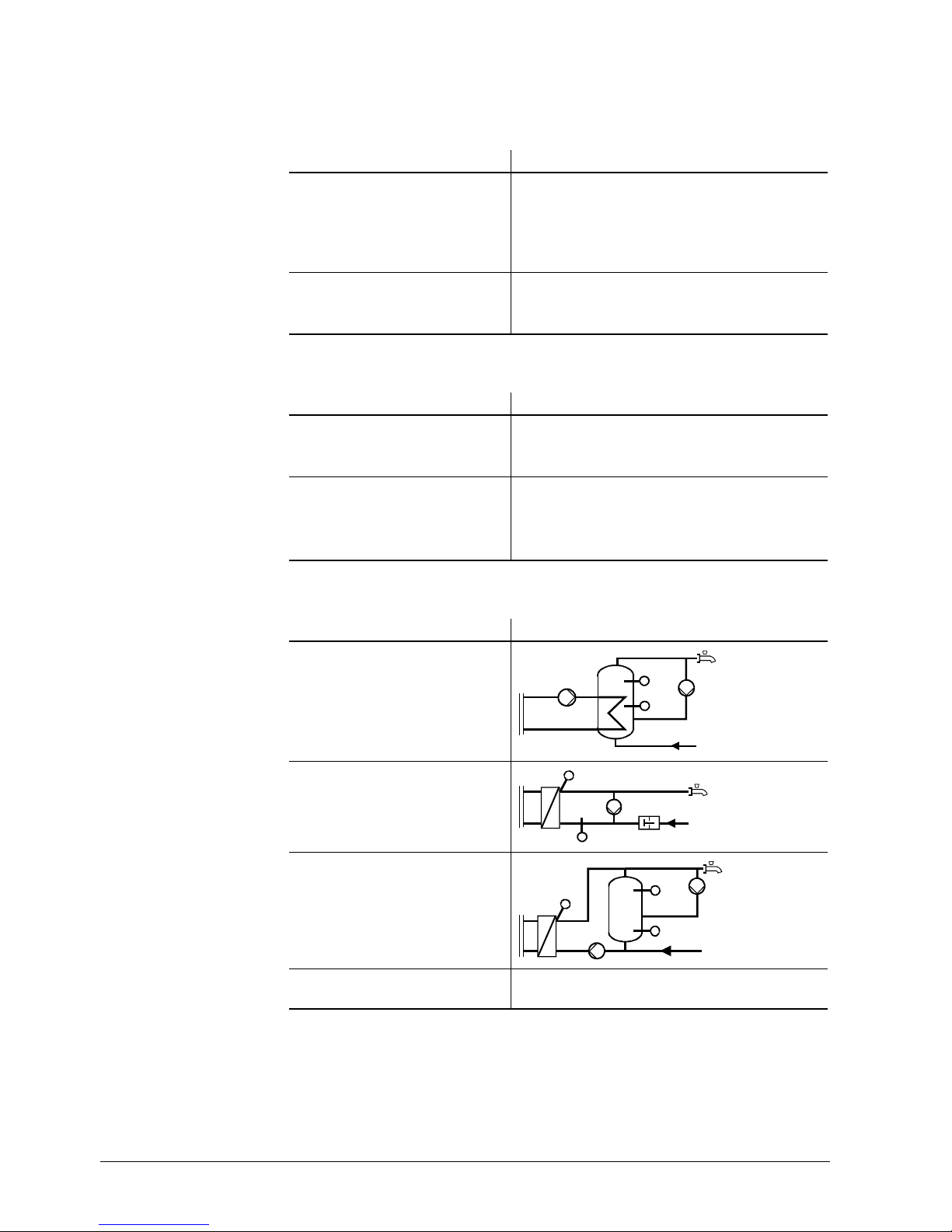
Term Explanation
Coil type storage tank
2383S33
Instantaneous d.h.w. heating
(via heat exchanger)
2383S34
Stratification storage tank
2383S35
Storage tank Common term used for coil type and stratification
storage tanks.
Heat source,
heat generation
Pumps
D.h.w. heating
Page 11

11/94
Siemens Building Technologies Basic Documentation RVD110, RVD130 CE1P2381E
HVAC Products 1 Summary 27.05.2004
1 Summary
1.1 Brief description and key features
• RVD110 / RVD130 are multifunctional district heating controllers for flow temperature
control of heating circuits and for the control of d.h.w. heating
• Their exclusive field of use are plants with district heat connection in smaller residen-
tial and nonresidential buildings
• The RVD110 has 3 plant types preprogrammed, the RVD130 has 8. When a certain
type of plant is selected, all functions and settings required for that particular plant
will be activated
• The RVD110 / RVD130 are designed as flow temperature controllers. The following
modes of control are possible:
− Weather-compensated only
− Weather- and room temperature compensated
− Room temperature-compensated only
• The difference between the RVD110 and RVD130 is the kind of d.h.w. heating:
− RVD110: 3 plant types, designed for straightforward d.h.w. heating with storage
tanks
− RVD130: 8 plant types, also suited for the more complex d.h.w. heating systems
that employ instantaneous d.h.w. heating
• In terms of regulating units, the RVD110 / RVD130 is designed for the control of 2-
and 3-port valves as well as diverting valves and pumps
• For the direct setting of the nominal room temperature setpoint, a knob is provided.
All the other parameters are set digitally using the operating line principle
• Key design features: Operating voltage AC 230 V, CE conformity, overall dimensions
to DIN 43700 (96 × 144 mm)
1.2 Type summary
Unit Type reference
Controller for basic plants
RVD110
Controller for the more complex plants
RVD130
1.3 Equipment combinations
1.3.1 Suitable sensors
• For the flow temperatures:
Suitable are all types of temperature sensors that use a sensing element LG-Ni 1000
Ω at 0 °C. The following types are presently available:
− Strap-on temperature sensor QAD22
− Immersion temperature sensor QAE22...
• For the return temperatures:
The following types are presently available:
− Strap-on temperature sensor QAD22 (sensing element LG-Ni
1000 Ω at 0 °C)
− Immersion temperature sensor QAE22... (sensing element LG-Ni 1000 Ω at 0 °C)
− For the primary return temperature (B7), also commercially available sensors with
a sensing element Pt 500 Ω
• For the outside temperature:
− Outside sensor QAC22 (sensing element LG-Ni 1000 Ω at 0 °C)
Page 12

12/94
Siemens Building Technologies Basic Documentation RVD110, RVD130 CE1P2381E
HVAC Products 1 Summary 27.05.2004
− Outside sensor QAC32 (sensing element NTC 575 Ω at 20 °C)
• For the room temperature:
Suited are PPS-compatible temperature sensors. The following type is presently
available:
− Digital room temperature sensor QAA10
• For the d.h.w. temperature and the secondary flow temperature of the heat ex-
changer:
− Strap-on temperature sensor QAD22
− Immersion temperature sensor QAE22...
1.3.2 Suitable room units
• Room unit QAW50
• Room unit QAW70
1.3.3 Suitable valve actuators
All Siemens actuators with the following features can be used:
• Electric or electrohydraulic actuators with a running time of 10...900 seconds
• 3-position control
• Operating voltage AC 24 V...230 V
1.3.4 Communication
The RVD110 / RVD130 are designed exclusively for standalone operation. There is no
bus connection facility.
1.3.5 Documentation
Type of documentation Classification number
Data Sheet RVD110/RVD130 N2381
Operating Instructions RVD110/RVD130 B2381
Installation Instructions RVD110/RVD130 G2381
Data Sheet QAW50 N1635
Installation Instructions QAW70 G1637
Data Sheet QAW70 N1637
Data Sheet QAA10 N1725
Page 13

13/94
Siemens Building Technologies Basic Documentation RVD110, RVD130 CE1P2381E
HVAC Products 2 Use 27.05.2004
2 Use
2.1 Types of plant
The RVD110 / RVD130 are suited for all types of in-house plants that
• are connected to a district heat network
• use weather- or room temperature-compensated flow temperature control
• have the control of d.h.w. heating integrated
2.2 Types of houses and buildings
Basically, the RVD110 / RVD130 are suited for all types of houses and buildings that
use weather- or room temperature-compensated flow temperature control, but are designed specifically for use in
• single-family houses
• multifamily houses
• small to medium-size nonresidential buildings
2.3 Types of heating systems
The RVD110 / RVD130 are suited for all standard heating systems, such as
• radiators
• convectors
• underfloor heating systems
• ceiling heating systems
• radiant panels
2.4 Heating circuit functions
The RVD110 / RVD130 are used if one or several of the following heating circuit functions is / are required:
• Weather- or room temperature-compensated flow temperature control
• Flow temperature control through a modulating seat or slipper valve
• Quick setback according to the selected 7-day program
• ECO function: Demand-dependent switching of the heating system based on the
type of building construction and the outside temperature
• 7-day program for the heating periods with a maximum of 3 setback periods per day
and daily varying on times
• Frost protection for the plant and the house or building
• Minimum and maximum limitation of the heating circuit’s flow temperature
• Maximum limitation of the room temperature
• Maximum limitation of the primary return temperature
• Maximum limitation of the temperature differential
2.5 D.h.w. functions
The RVD110 / RVD130 are used if 1 or several of the following d.h.w. functions is / are
required:
• D.h.w. heating via heat exchanger in the storage tank
• Instantaneous d.h.w. heating via heat exchanger, with or without mixing valve in the
d.h.w. circuit
• Instantaneous d.h.w. heating via heat exchanger, with storage tank, with or without
mixing valve in the d.h.w. circuit
Page 14

14/94
Siemens Building Technologies Basic Documentation RVD110, RVD130 CE1P2381E
HVAC Products 2 Use 27.05.2004
• Common or separate heat exchangers for the heating circuit and d.h.w. heating
• Own 7-day switching program for the release of d.h.w. heating and the circulating
pump
• Idle heat function in case of instantaneous d.h.w. heating connected to a parallel
heat exchanger
• Legionella function
• Forced d.h.w. charging
• Frost protection for the d.h.w.
• Selectable priority: Absolute, shifting, or parallel
• Manual charging outside the time program
• Maximum limitation of the d.h.w. return temperature
• Maximum limitation of the return temperature differential (DRT limitation)
The RVD110 cannot perform all functions listed above.
2.6 Auxiliary functions
The RVD110 / RVD130 are used if one or several of the following auxiliary functions is /
are required:
• Periodic pump run
• Pump overrun
• Display of parameters, actual values, operating state and fault status messages
• Remote operation via room unit
• Service functions
• Pulse lock for the actuators
Note
Page 15

15/94
Siemens Building Technologies Basic Documentation RVD110, RVD130 CE1P2381E
HVAC Products 3 Fundamentals 27.05.2004
3 Fundamentals
3.1 Key technical features
The controllers offer 2 key technical features:
The RVD110 has 3 plant types preprogrammed, the RVD130 has 8.
Section 3.2 ”Plant types” shows them in the form of plant diagrams
Plant type RVD110 RVD130 D.h.w. system
1
z z
−
2
z z
D.h.w. via storage tank
3
z z
D.h.w. via storage tank
4
z Instantaneous d.h.w. heating, d.h.w. via second
heat exchanger
5
z Instantaneous d.h.w. heating, d.h.w. via second
heat exchanger
6
z Instantaneous d.h.w. heating via storage tank,
connected to second heat exchanger
7
z Instantaneous d.h.w. heating via storage tank,
connected to second heat exchanger
8
z
Storage tank connected to heat exchanger
The settings are assigned to setting levels each of which accommodates a number of
function blocks:
Setting level Function block
End-user space heating
Clock setting
End-user d.h.w. heating
Display actual value sensors
End-user
Standard values and fault indication
Plant configuration
Space heating
Actuator heat exchanger
Actuator heating circuit
D.h.w. heating
D.h.w. actuator 1
D.h.w. actuator 2
Extra legionella functions
Heating engineer
Test and display
Locking functions Locking functions
For each function block, the required settings can be made on operating lines. The
description of the individual functions is given below, per block and line.
3.2 Plant types
• The RVD110 has 3 plant types preprogrammed
• The RVD130 has 8 plant types preprogrammed
The required functions are ready assigned to each type of plant. When commissioning
the heating plant, the relevant plant type must be selected.
With the existing choice of controllers and plant types, practically all types of heating
plants with district heat connection and own d.h.w. heating facility can be controlled.
Note on the plant diagrams: All elements (sensors B7 and B71, circulating pump, and
flow switch) shown with broken lines are optional.
Plant types
Function blocks
Page 16
16/94
Siemens Building Technologies Basic Documentation RVD110, RVD130 CE1P2381E
HVAC Products 3 Fundamentals 27.05.2004
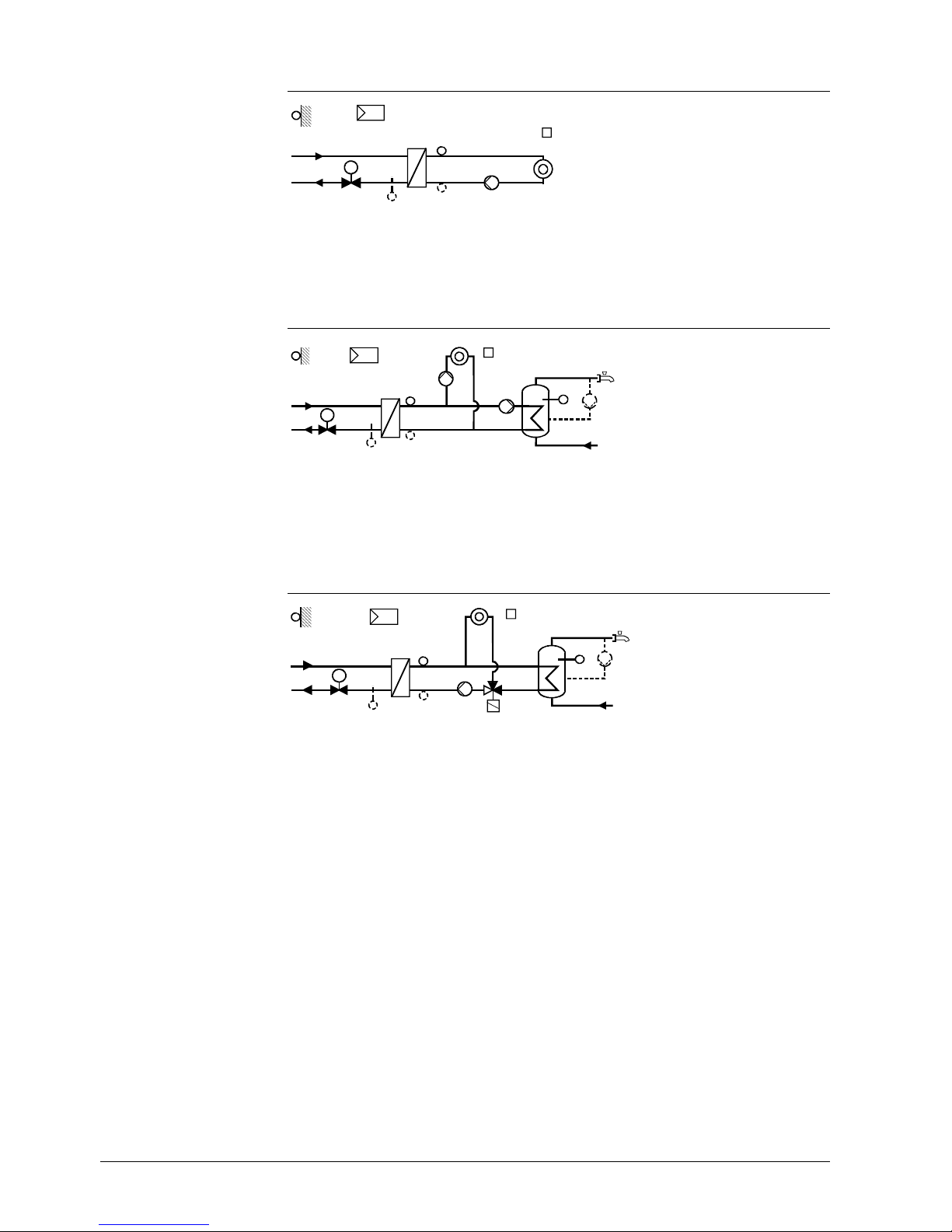
3.2.1 Plant type no. 1
Y1
B7
B71
B1
Q1
B9
A6
2381S01
N1
M
Heating circuit control without d.h.w. heating
3.2.2 Plant type no. 2
B3
Q7
Y1
B7
B71
B1
Q1
Q3
A6
B9
N1
2381S02
M
D.h.w. heating with storage tank, d.h.w. charging via charging pump.
Only with RVD130: Circulating pump optional
3.2.3 Plant type no. 3
Y1
B7
B71
Q1
B1
Y7
B9
N1
B3
Q7
2381S03
A6
M
D.h.w. heating via storage tank, d.h.w. charging via diverting valve.
Only with RVD130: Circulating pump optional
A6 Room unit
B1 Flow temperature sensor (controlled variable)
B3 D.h.w. temperature sensor
B7 Primary return temperature sensor
B71 Secondary return temperature sensor in the heating circuit
B9 Outside sensor
N1 Controller
Q1 Heating circuit pump
Q3 D.h.w. charging pump
Q7 D.h.w. circulating pump
Y1 2-port valve in the primary return
Y7 Diverting valve
Legend for plant types
no. 1...3:
Page 17
17/94
Siemens Building Technologies Basic Documentation RVD110, RVD130 CE1P2381E
HVAC Products 3 Fundamentals 27.05.2004
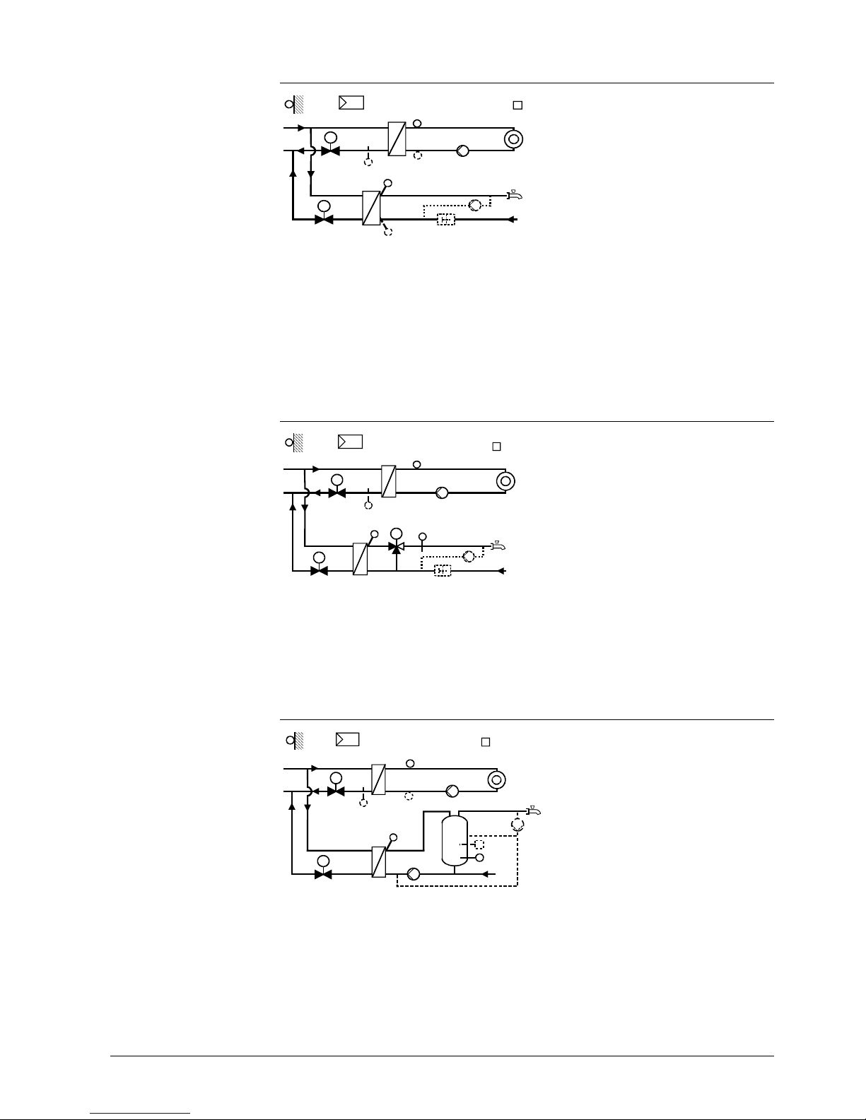
3.2.4 Plant type no. 4
Y1
Y5
H5
A6
B9
B7 B71
B1
Q1
B3
Q7
2381S0 4
N1
B71
M
M
Separate heat exchangers for heating circuit and d.h.w. heating, instantaneous d.h.w.
heating via heat exchanger.
Temperature sensor B71 can be used as follows:
• As a d.h.w. temperature sensor, or
• For maximum limitation of the temperature differential
Circulating pump and flow switch optional. Selectable idle heat function.
3.2.5 Plant type no. 5
B1
Y1
Y5
B7
Q1
A6
B9
2381S05
N1
Y7
B3
B71
M
M
M
H5
Q8
Separate heat exchangers for heating circuit and d.h.w. heating; 2-stage d.h.w. control:
first stage in the primary return, second stage with a mixing valve in the secondary flow.
Circulating pump and flow switch optional. Selectable idle heat function.
3.2.6 Plant type no. 6
B1
Y1
Y5
B7
Q1
A6
B9
B3
B71
F1
Q3
B71
Q7
2381S0 6
N1
M
M
Separate heat exchangers for heating circuit and d.h.w. heating; instantaneous d.h.w.
heating via storage tank connected to a separate heat exchanger; d.h.w. charging via
charging pump. Temperature sensor B71 can be used as follows:
• As a d.h.w. temperature sensor, or
• For maximum limitation of the temperature differential; in that case, the d.h.w. tem-
perature must be acquired with thermostat F1
Page 18

18/94
Siemens Building Technologies Basic Documentation RVD110, RVD130 CE1P2381E
HVAC Products 3 Fundamentals 27.05.2004
3.2.7 Plant type no. 6b
B1
Y1
Y7
B7
Q1
A6
B9
B71
Q7
2381S0 9
N1
M
Heat exchanger for the heating circuit, d.h.w. heating via the district heat primary circuit, control of the d.h.w. temperature via an electrothermal actuator. Circulating pump
optional. For information, refer to section 14.5 ”Plant type no. 6b”.
3.2.8 Plant type no. 7
Y1
B7
B1
Q1
A6
B9
B3
Q3
Y5
B71
2381S07
N1
B71
F1
M
M
Q8
2 heat exchangers connected in series, 1 for the space heating circuit and 1 for d.h.w.
heating; instantaneous d.h.w. heating via storage tank connected to the second heat
exchanger which uses a mixing circuit for d.h.w. control. Temperature sensor B71 can
be used as follows:
• As a d.h.w. temperature sensor, or
• For maximum limitation of the temperature differential; in that case, the d.h.w. tem-
perature must be acquired with thermostat F1
3.2.9 Plant type no. 8
A6
B9
B71
Q1
Q7
Q3
Y1
B7
B1
Y5
B3
2381S08
N1
M
M
D.h.w. heating with storage tank connected to the heat exchanger; heating circuit with
mixing circuit in the heating zone flow; d.h.w. charging via charging pump.
Page 19
19/94
Siemens Building Technologies Basic Documentation RVD110, RVD130 CE1P2381E
HVAC Products 3 Fundamentals 27.05.2004
A6 Room unit
B1 Flow temperature sensor heating circuit (plant types no. 4...6)
or common flow (plant types no. 7+8)
B3 D.h.w. temperature sensor
B7 Primary return temperature sensor
B71 Secondary return temperature sensor (plant types no. 4 and 7)
or d.h.w. temperature sensor 2 (plant
type no. 5)
or flow temperature sensor heating circuit (plant type no. 8)
B9 Outside sensor
F1 D.h.w. thermostat
H5 Flow switch
N1 Controller
Q1 Heating circuit pump
Q3 D.h.w. charging pump
Q7 D.h.w. circulating pump controlled by the controller
Q Externally controlled circulating pump
Y1 2-port valve in the primary return
Y5 2-port valve in the d.h.w. circuit (plant types no. 4...6)
or mixing valve in the d.h.w. circuit (plant type no. 7)
or in the heating circuit (plant type no. 8)
Y7 Mixing valve in the d.h.w. circuit (plant type no. 5) or 2-port valve in the primary return (plant type no. 6b)
3.3 Operating modes
3.3.1 Heating circuit control
The RVD110 / RVD130 offer the following operating modes:
Automatic mode
• Automatic heating operation, changeover between nominal and reduced
room temperature according to the time program
• Demand-dependent switching of the heating system based on the pro-
gression of the outside temperature while giving consideration to the
building’s thermal inertia (automatic ECO function)
• Optional remote operation via room unit
• Frost protection is ensured
Continuous operation
• Heating operation with no time program
• Heating to the room temperature adjusted with the setting knob
• Automatic ECO function inactive
• Frost protection is ensured
Standby
• Heating to the frost protection level
• Frost protection is ensured
3.3.2 D.h.w. heating
D.h.w. heating ON / OFF
• ON (button lit): D.h.w. is heated independent of the heating circuit’s op-
erating mode and control (no d.h.w. heating during holiday periods)
• OFF (button dark): No d.h.w. heating; circulating pump switches off, frost
protection is ensured
3.3.3 Manual operation
Manual operation
• No control
• Heating circuit pump and d.h.w. pump(s) are running
• 2-port vale in the primary circuit can be manually operated with the setting
buttons
For more detailed information, refer to chapter 21 “Manual operation”.
Legend for plant
types no. 4...8:
Page 20

20/94
Siemens Building Technologies Basic Documentation RVD110, RVD130 CE1P2381E
HVAC Products 4 Acquisition of the measured values 27.05.2004
4 Acquisition of the measured values
4.1 General
In the event of a faulty sensor, the RVD110 / RVD130 always attempt to maintain the
required comfort level, even at the expense of certain heat losses, which will not cause
any damage however.
In the case of severe faults that make it impossible for the RVD110 / RVD130 to ensure
control, a fault status message will be delivered. The controller displays this as Er (error).
Optional sensors (shown with broken lines) cannot be monitored for open-circuits.
4.2 Flow temperature (B1)
4.2.1 Types of sensors
Suitable are all types of Siemens temperature sensors that use a sensing element LG-
Ni 1000 Ω at 0 °C:
• Strap-on temperature sensor QAD22
• Immersion temperature sensor QAE22...
4.2.2 Handling faults
If there is a fault in the sensor’s measuring circuit (short-circuit or open-circuit), the
controller will respond as follows (with all plant types):
• The heating circuit pump will be activated
• The 2-port valve in the primary return will be shut
If plant types no. 4...6 use no space heating, no fault status message will be generated.
In all other cases, a fault status message will be delivered:
• The controller’s LCD displays Er
• When interrogating the flow temperature on the QAW70 room unit – if present – its
display will show --- if there is a short-circuit or open-circuit
4.3 Outside temperature (B9)
4.3.1 Types of sensors
The following types of sensors can be used:
• Outside sensor QAC22 (sensing element LG-Ni 1000 Ω at 0 °C), for connection to
terminal B9
• Outside sensor QAC32 (sensing element NTC 575 Ω at 20 °C), for connection to
terminal B9
The controller automatically identifies the type of sensor connected.
The range of use is –50...+50 °C.
4.3.2 Handling faults
If there is a short-circuit or open-circuit in the outside sensor’s measuring circuit, the
controller will respond as follows:
• Plants with room temperature sensor:
The controller switches to pure room temperature control.
Page 21

21/94
Siemens Building Technologies Basic Documentation RVD110, RVD130 CE1P2381E
HVAC Products 4 Acquisition of the measured values 27.05.2004
• Plants with no room temperature sensor:
The controller operates with a fixed outside temperature of 0 °C
A fault status message will be generated only when there is no actual room temperature value available.
This is the case when no room unit is used or when the room temperature measuring
circuit is faulty:
• The controller’s LCD displays Er
• When interrogating the outside temperature on the QAW70 room unit – if present –
its display will show --- if there is a short-circuit or open-circuit
4.4 Room temperature (A6)
4.4.1 Types of sensors
The room temperature is acquired via a PPS (point-to-point interface). Only a unit with
an appropriate output signal can be connected to it. The following types of units can be
used:
• Room unit QAW50
• Room unit QAW70
• Room temperature sensor QAA10
4.4.2 Handling faults
A short-circuit in the measuring circuit leads to a fault status message.
An open-circuit in the measuring circuit does not lead to a fault status message since it
is not possible to have a room unit connected.
4.4.3 Room model
The RVD110 / RVD130 feature a room model which is integrated in the controller. It
simulates the room temperature based on the progression of the outside temperature
and the type of building construction, using a defined attenuation. In plants with no
room temperature measurement, it can perform certain room functions.
4.5 D.h.w. temperature (B3 or B71)
4.5.1 Types of sensors
The required types of sensors depend on the type of plant:
• Plant types no. 2...8 (sensor input B3):
Suitable are:
− All Siemens sensors using a sensing element LG-Ni 1000 Ω at 0 °C. Suited are
the strap-on temperature sensor QAD22 and the immersion temperature sensor
QAE22 with a range of use of 0...130 °C
− Commercially available sensors using a sensing element Pt 500 Ω with a range of
0...140 °C
The controller is able to automatically identify the type of sensor used.
• Storage tank with plant types no. 6 and 7 (sensor input B71):
− Suited are all Siemens sensors using a sensing element LG-Ni 1000 Ω at 0 °C
− The d.h.w. temperature in the storage tank can also be acquired with a control
thermostat
Page 22

22/94
Siemens Building Technologies Basic Documentation RVD110, RVD130 CE1P2381E
HVAC Products 4 Acquisition of the measured values 27.05.2004
4.5.2 Handling faults
If there is a fault in the sensor’s measuring circuit (short-circuit or open-circuit), a fault
status message will be generated.
The d.h.w. charging pump or the diverting valve will be deactivated and, in the case of
instantaneous d.h.w. heating systems, the respective valve shut. When interrogating the
d.h.w. temperature on the QAW70 room unit, its display will show --- if there is a shortcircuit or open-circuit.
4.6 Primary return temperature (B7)
4.6.1 Measurement
This measured value is required for minimum and maximum limitation of the primary
return temperature and for DRT limitation.
The following types of sensors can be used:
• Strap-on temperature sensor QAD22 or immersion temperature sensor QAE22...
(sensing element LG-Ni 1000 Ω at 0 °C)
• Commercially available immersion temperature sensors with a sensing element
Pt 500 Ω at 0 °C
The controller automatically identifies the type of sensor used.
The range of use of all types of sensors is 0...140 °C. The Pt sensors can be used for
fluid temperatures up to180 °C.
4.6.2 Handling faults
If the primary return temperature sensor becomes faulty (short-circuit or open-circuit), a
fault status message will be generated as soon as maximum limitation of the return
temperature or DRT limitation has become active. In that case, the controller’s LCD will
display Er.
4.7 Multipurpose temperature sensor (B71)
4.7.1 Use and measurement
Depending on the type of plant and the configuration, the multipurpose temperature
sensor is used as a
• secondary return temperature sensor
• d.h.w. temperature sensor
• heating circuit flow temperature sensor
The sensor acquires the temperature with a sensing element LG-Ni 1000
Available are the strap-on temperature sensor QAD22 and the immersion temperature
sensor QAE22... with a measuring range of 0...140 °C.
4.7.2 Handling faults
• When used as a secondary return temperature sensor:
If there is a fault in the sensor’s measuring circuit (short-circuit or open-circuit), a
fault status message will be generated when DRT limitation is activated. In that case,
the controller’s LCD will display Er
• When used as d.h.w. temperature sensor:
If there is a fault in the sensor’s measuring circuit (short-circuit or open-circuit), a
Page 23

23/94
Siemens Building Technologies Basic Documentation RVD110, RVD130 CE1P2381E
HVAC Products 4 Acquisition of the measured values 27.05.2004
fault status message will always be generated. In that case, the controller’s LCD will
display Er
• When used as a heating circuit flow temperature sensor (plant type no. 8):
If there is a fault in the sensor’s measuring circuit (short-circuit or open-circuit), a
fault status message will always be generated. The heating circuit’s mixing valve will
close and the circulating pump remains activated. The controller’s LCD will display
Er
Page 24
24/94
Siemens Building Technologies Basic Documentation RVD110, RVD130 CE1P2381E
HVAC Products 5 Function block End-user space heating 27.05.2004
5 Function block End-user space
heating
This function block contains settings and readouts that are intended for the end-user.
5.1 Operating lines
The buttons for selecting the operating lines and for adjusting the settings are described in section 22.1 ”Operation”.
Line Function, parameter Unit Factory setting Range
1 Current nominal room temperature setpoint Display function
2 Reduced room temperature setpoint °C 14 variable*
3 Frost protection / holiday mode setpoint °C 8 8...variable*
5 Heating curve slope 15 2.5...40
6 Weekday for entering the heating program Current weekday 1...7, 1-7
7 Heating period 1 start hh:min 06:00 --:-- / 00:00...24:00
8 Heating period 1 end hh:min 22:00 --:-- / 00:00...24:00
9 Heating period 2 start hh:min --:-- --:-- / 00:00...24:00
10 Heating period 2 end hh:min --:-- --:-- / 00:00...24:00
11 Heating period 3 start hh:min --:-- --:-- / 00:00...24:00
12 Heating period 3 end hh:min --:-- --:-- / 00:00...24:00
* The variable setting ranges are defined in the following sections
5.2 Settings and displays
• The nominal room temperature setpoint is set with the setpoint knob. Its scale is
calibrated in °C room temperature. The room temperature is maintained at that setpoint:
− In automatic mode during the heating periods
− In continuous operation at all times
• On operating line 1, the LCD displays the current setpoint, depending on the operat-
ing mode and the operating state:
Operating mode or operating state
Setpoint displayed
Heating to nominal setpoint Adjustment made with the setpoint knob (incl. read-
justment made on the room unit)
Heating to reduced setpoint Reduced setpoint (setting operating line 2)
Continuous operation Adjustment made with the setpoint knob
Quick setback Reduced setpoint (setting operating line 2)
Frost protection mode Setpoint for frost protection (setting operating line 3)
OFF by ECO • During heating periods: Adjustment made with
the setpoint knob (incl. readjustment made on the
room unit)
• Outside the heating periods: Reduced setpoint
• The reduced room temperature setpoint is to be set on operating line 2. The setting
range is generated by the nominal room temperature setpoint and the setpoint for
frost protection. This setpoint is maintained outside the heating periods
• The setpoint for frost protection is to be set on operating line 3. The setting range lies
between 8 °C (fixed value) and the adjusted reduced setpoint. This frost protection
thus acts as frost protection of the building.
The setting also represents the setpoint for the holiday mode. A holiday program can
only be entered on the QAW70 room unit, however
• The d.h.w. temperature setpoint is to be set on operating line 4. Its setting range
depends on the type of plant. For detailed information, refer to section 16.5
“Maximum setpoint”
Page 25

25/94
Siemens Building Technologies Basic Documentation RVD110, RVD130 CE1P2381E
HVAC Products 5 Function block End-user space heating 27.05.2004
• The heating curve slope is to be set on operating line 5. The setting range is 2.5 to
40, but the effective slope is 10 times smaller.
For detailed information, refer to section 11.3 ”Heating curve”.
The setpoint of the nominal and the reduced room temperature as well as that for frost
protection are to be entered directly in °C room temperature. These setpoints apply
irrespective of whether or not the control uses a room temperature sensor. If there is no
room temperature sensor, the room model will be used.
5.3 Heating program
The heating program of the RVD110 / RVD130 offers 3 heating periods per day. Also,
every weekday can use different heating periods. Each heating period is defined by a
start and an end time.
When entering ”1-7” on operating line 6, the heating program applies to all weekdays.
The entry can be simplified as follows: If the times for the weekend differ from those for
the other weekdays, first enter the times for the entire week and then change weekdays
6 and 7 as required.
The settings are sorted and overlapping heating periods combined. When setting --:-for the start or the end, the heating period will be negated.
With the QAW70 room unit, the heating program can be changed from a remote location.
Page 26

26/94
Siemens Building Technologies Basic Documentation RVD110, RVD130 CE1P2381E
HVAC Products 6 Function block Clock settings 27.05.2004
6 Function block Clock settings
6.1 Operating lines
Line Function, parameter Unit Factory setting Range
13 Time of day hh:min Undefined 00:00...23:59
14 Weekday d 1 1...7
15 Date dd.MM 01.01 01.01. … 31.12.
16 Year yyyy 2004 1995…2094
6.2 Entries
The RVD110 / RVD130 have a yearly clock with the time of day, weekday and date.
The changeover from summer- to wintertime, and vice versa, takes place automatically.
Should the respective regulations change, the changeover dates can be adjusted (refer
to operating lines 57 and 58).
Page 27
27/94
Siemens Building Technologies Basic Documentation RVD110, RVD130 CE1P2381E
HVAC Products 7 Function block End-user d.h.w. heating 27.05.2004
7 Function block End-user d.h.w. heat-
ing
7.1 Operating lines
Line Function, parameter Unit Factory setting Range
17 Weekday for entering the d.h.w. program Current weekday 1...7, 1-7
18 Release period 1 start hh:min 06:00 00:00...24:00
19 Release period 1 end hh:min 22:00 00:00...24:00
20 Release period 2 start hh:min --:-- 00:00...24:00
21 Release period 2 end hh:min --:-- 00:00...24:00
22 Release period 3 start hh:min --:-- 00:00...24:00
23 Release period 3 end hh:min --:-- 00:00...24:00
41 D.h.w. normal setpoint °C 55 variable
42 D.h.w reduced setpoint °C 40 8…normal setpoint
Setting --:-- means: Release period is inactive
7.2 D.h.w. program
The d.h.w. program of the RVD110 / RVD130 affords 3 release periods per day. Also,
every weekday can have different release periods. Each release period is defined by a
start and an end time.
When entering ”1-7” on operating line 17, the d.h.w. program applies to all weekdays.
The entry can be simplified as follows: If the times for the weekend differ from those for
the other weekdays, first enter the times for the entire week and then change weekdays
6 and 7 as required.
The settings are sorted and overlapping release periods combined.
When setting --:-- for the start or the end, the release period will be negated.
However, the release of d.h.w. heating can also take place according to other programs. The selection is made on operating line 101.
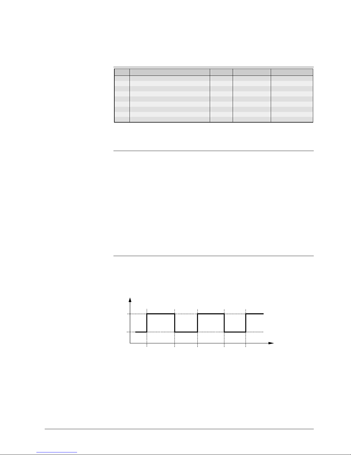
7.3 Setpoint adjustments
• The nominal d.h.w. setpoint is to be set on operating line 41. Its setting range de-
pends on the type of plant (for details, refer to section 16.5 “Maximum setpoint“.
• The reduced d.h.w. setpoint can be adjusted on operating line 42 between 8 °C and
the nominal setpoint. In connection with the d.h.w. program, it takes effect between
the release phases (refer to the above section 7.2).
Nom
Red
w
BW
2381D06
t
06:00 08:00 11:30 13:30 16:00
Nom Nominal setpoint
Red Reduced setpoint
t Time
w
BW
D.h.w. setpoint
Page 28

28/94
Siemens Building Technologies Basic Documentation RVD110, RVD130 CE1P2381E
HVAC Products 8 Function block Display actual value sensors 27.05.2004
8 Function block Display actual value
sensors
8.1 Operating lines
Line Function, parameter Unit Factory setting Range
24 Room temperature (terminal A6) °C Display function
25 Outside temperature °C Display function
26 D.h.w. temperature °C Display function
27 Flow temperature heating circuit °C Display function
8.2 Displays
• Room temperature:
If a room temperature sensor or room unit is connected to the PPS interface (A6),
the temperature acquired will be displayed
• Outside temperature:
The outside temperature displayed is delivered by the outside sensor (analog, connected to B9)
• D.h.w. temperature:
Displayed will be the temperature acquired by the d.h.w. temperature sensor. Depending on the plant configuration, this may be the sensor connected to B3 or B71
• If the storage tank temperature (plant types no. 6 and 7) is acquired with a control
thermostat, the display will always show --- .
• Flow temperature heating circuit:
Plant types no. 1...7: Displayed will be the temperature acquired by the sensor connected to B1.
Plant type no. 8: Displayed will be the temperature acquired by the sensor connected
to B71
Page 29

29/94
Siemens Building Technologies Basic Documentation RVD110, RVD130 CE1P2381E
HVAC Products 9 Function block Standard values and fault indication 27.05.2004
9 Function block Standard values and
fault indication
9.1 Operating lines
Line Function, parameter Unit Factory setting Range
49 Reset of operating lines 2...23 (end-user level) 0 0 / 1
50 Display of faults Display function
9.2 Reset end-user level
If operating line 49 is set to 1, all the current settings on the end-user level (operating
lines 2...23) will be cleared. In that case, the factory settings will be used again.
Proceed as follows:
1. Select operating line 49.
2. Keep buttons
and depressed until the display changes. A flashing 0 on the
display is the normal status.
3. If 1 appears, the controller has retrieved the factory settings.
9.3 Display of faults
Faults in the measuring circuits detected by the controller appear on the display as Er
(error) as well as on operating line 50, accompanied by an error code:
Error code Cause
10 Fault outside sensor
30 Fault flow temperature sensor
40 Fault return temperature sensor on the primary side
42 Fault return temperature sensor on the secondary side
50 Fault d.h.w. temperature sensor
61 Fault room unit
62 Device with wrong PPS identification connected
86 Short-circuit on the room unit bus (PPS)
Page 30

30/94
Siemens Building Technologies Basic Documentation RVD110, RVD130 CE1P2381E
HVAC Products 10 Function block Plant configuration 27.05.2004
10 Function block Plant configuration
10.1 Operating lines
Line Function, parameter Unit Factory setting Range
51 Plant type 1 RVD110: 1...3
RVD130: 1...8
52 Space heating present 1 0 / 1
53 Use of universal sensor at terminal B71 1 0 / 1
54 Flow switch / circulating pump present
(offsetting heat losses)
0 0...3
55 Return flow of circulating pump 0 0...2
56 Pump kick 1 0 / 1
57 Winter- / summertime changeover dd.MM 25.03 01.01. …31.12
58 Summer- / wintertime changeover dd.MM 25.10 01.01. …31.12
10.2 Plant configuration
• With the RVD110, plant types no. 1...3 are available; with the RVD130, all plant
types (1...8). For a detailed description of the individual plant types, refer to section
3.2 ”Plant types”
• With plant types no. 2...8, it is possible to have no space heating and to use the
RVD110 / 130 for d.h.w. heating only (setting 0 on operating line 52)
• With plant types no. 4, 6 and 7, the temperature sensor connected to terminal B71
can be used in 1 of 2 ways:
− As a return temperature differential sensor: In that case, it is used as a return
temperature sensor in the heating circuit’s secondary return. The d.h.w. temperature must then be acquired with a thermostat, to be connected to the binary input
H5. Entry on operating line 53 = 0
− As a d.h.w. temperature sensor: In that case, the return temperature differential
cannot be measured. Entry on operating line 53 = 1
• With plant types no. 4 and 5, it must be entered on operating line 54 whether a flow
switch or circulating pump, or both, are present.
For detailed information, refer to subsection 17.4.4 “Offsetting the heat losses”
• With plant types no. 6 and 7, it is possible to select on operating line 55 where the
return water of the circulating pump shall be fed:
− The return water will be fed to the d.h.w. storage tank or there is no circulating
pump present (setting = 0)
− The return water is fed to the return of the d.h.w. heat exchanger (setting = 1)
For more information, refer to section 17.5 ”Instantaneous d.h.w. heating with stor-
age tanks”.
Through the selection of the required plant type, heating circuit, sensor connected to
B71, flow switch and return water of circulating pump, all functions and settings required for the respective type of plant, and the assigned operating lines, will be activated. All other operating lines remain deactivated.
10.3 Device functions
• The pump kick function can be activated or deactivated on operating line 146 (refer
to section 11.10.2 “Pump kick“)
• The change from wintertime to summertime, and vice versa, is made automatically. If
international regulations change, the relevant changeover dates can be entered on
operating lines 144 and 145. The entry to be made is the earliest possible changeover date. The weekday on which changeover occurs is always a Sunday
Example
If the start of summertime is specified as "The last Sunday in March", the earliest
Page 31

31/94
Siemens Building Technologies Basic Documentation RVD110, RVD130 CE1P2381E
HVAC Products 10 Function block Plant configuration 27.05.2004
possible changeover date is March 25. In that case, the date to be entered on operating line 144 is 25.03.
If no summer- / wintertime changeover is required, the 2 dates are to be set so that
they coincide.
Page 32

32/94
Siemens Building Technologies Basic Documentation RVD110, RVD130 CE1P2381E
HVAC Products 11 Function block Space heating 27.05.2004
11 Function block Space heating
11.1 Operating lines
Line Function, parameter Unit Factory setting Range
61 Heating limit (ECO) K –3 --- / –10...+10
62 Building structure 1 0 / 1
63 Quick setback with room temperature sensor 1 0...15
66 Adaptation of heating curve 0 0 / 1
69 Heat gains K 0 –2...+4
70 Room temperature influence (gain factor) 10 0...20
71 Parallel displacement of heating curve K 0.0 –4.5...+4.5
72 Overrun time heating circuit pump min 4 0...40
73 Frost protection for the plant 1 0 / 1
74 Max. limitation of room temperature K --- --- / 0.5...4
Setting --- means: Function is inactive; for additional setting notes, refer to the descriptions of the individual
functions
11.2 Compensating variables
11.2.1 Outside temperature
The RVD110 / RVD130 differentiate between 3 types of outside temperatures:
• The actual outside temperature (T
A
)
• The attenuated outside temperature (T
AD
): This temperature is generated by filtering
the actual outside temperature through the building time constant of 21 hours (fixed
value). This means that, compared to the actual outside temperature, the attenuated
outside temperature is considerably damped, thus representing the long-term development of the outside temperature. The building time constant is a measure of the
type of building construction and an indication of how quickly the room temperature
in the building would change if the outside temperature suddenly changed. It can be
selected:
− Heavy building structures: Setting 0 on operating line 62
− Light building structures: Setting 1 on operating line 62
• The composite outside temperature (T
AM
): This temperature is made up of the above
2 outside temperatures, depending on the type of building construction (can be selected on operating line 62):
Building
construction
Entry on operating line 62
Proportion of actual
outside temperature (T
A
)
Proportion of attenuated
outside temperature (TAD)
Heavy 0 50 % 50 %
Light 1 75 % 25 %
Using these weightings, the composite outside temperature is less damped than the
attenuated outside temperature (T
AD
).
The composite outside temperature (T
AM
) suppresses unnecessary reactions of the
control system if the outside temperature changes for short periods of time.
In the case of the weather-compensated types of control (with or without room temperature influence), the RVD110 / RVD130 use the composite outside temperature.
When operating line 25 is selected (display of the actual outside temperature) and buttons
and are pressed simultaneously for about 3 seconds, both the attenuated
and the composite outside temperature adopt the current measured value. This means
that the generation of the 2 variables is restarted (outside temperature reset).
Tip
Page 33

33/94
Siemens Building Technologies Basic Documentation RVD110, RVD130 CE1P2381E
HVAC Products 11 Function block Space heating 27.05.2004
TA (B9)
2381B04
T
A
T
AD
T
AM
25 / 50 %
75 / 50 %
k
t
= 21 h
Generation of composite and attenuated outside temperature
0
5
10
15
20
25
T
AD
T
AM
t
2522D17
T
A
T
A
Progression of actual, composite and attenuated outside temperature
TA Actual outside temperature
T
AD
Attenuated outside temperature
k
t
Building time constant
T
AM
Composite outside temperature
t Time
11.2.2 Room temperature
The room temperature is considered by the control as follows:
• With room temperature-compensated flow temperature control, the deviation of the
actual room temperature from the setpoint is the only compensating variable
• With weather-compensated control with room temperature influence, the room tem-
perature is an additional compensating variable
It is possible to adjust a gain factor for the influence of the room temperature (operating
line 70). This gain factor indicates to what extent a room temperature deviation will
affect the room temperature setpoint, thereby acting indirectly (via the heating curve
slope) on the flow temperature control:
0 = no effect of the room temperature deviation on generation of the setpoint
20 = maximum effect of the room temperature deviation on generation of the setpoint
For that purpose, a room temperature sensor (room unit) must be present.
2462D05
wR - x
R
E
Gain factor of room temperature deviation
–∆w
R
Reduction of room temperature setpoint
+
∆w
R
Increase of room temperature setpoint
E Authority
w
R-xR
Setpoint minus actual value (room temperature)
Page 34

34/94
Siemens Building Technologies Basic Documentation RVD110, RVD130 CE1P2381E
HVAC Products 11 Function block Space heating 27.05.2004
Calculation of the setpoint change ∆w
R
is made in the steady state according to the
following formula:
Room authority E
∆w
R
=
2
× ( wR - xR )
2462D06
S
Effect of room temperature setpoint change on the flow temperature setpoint
∆w
R
Change of room temperature setpoint
s Slope of heating curve
∆w
VT
Change of flow temperature setpoint
The flow temperature setpoint change ∆w
VT
is calculated according to the following
formula:
∆w
VT
= ∆w
R
× ( s × 0.1 + 1 )
11.3 Heating curve
11.3.1 General, basic setting
With weather-compensated flow temperature control (with or without room temperature
influence), the assignment of the flow temperature setpoint to the outside temperature
is made via the heating curve. The heating curve slope is to be set on operating line 5.
20 10
0
-10 -20 -30
90
80
70
60
50
40
30
40
35 30 27,5 25 22,5
20
17,5
15
12,5
10
7,5
5
2,5
100
2381D05
T
V
T
AM
110
20
S
=
S Slope
T
AM
Composite outside temperature
T
V
Flow temperature
The heating curve has a fixed tilting point at an outside temperature of 22 °C and a flow
temperature of 20 °C. It can be adjusted around this point in the range 2.5 ...40 in increments of 0.5.
Each heating curve has a substitute line which intersects the tilting point and ”its” heating curve at an outside temperature of 0 °C. Its slope is set on the controller and is
calculated as follows:
10 × ∆T
V
s =
∆T
AM
Page 35

35/94
Siemens Building Technologies Basic Documentation RVD110, RVD130 CE1P2381E
HVAC Products 11 Function block Space heating 27.05.2004
A substitute line is needed because the heating curve is slightly deflected. This is required to compensate for the nonlinear radiation characteristics of the different types of
radiators.
The basic setting is made according to the planning documentation or local practices.
The heating curve is based on a room temperature setpoint of 20 °C.
11.3.2 Self-adaptation
The heating curve is defined by its slope and a possible parallel displacement both of
which are adjustable. By changing its slope and by considering heat gains, the heating
curve can adapt to environmental conditions. The learning steps become smaller as the
number of operating hours increase.
The selection of self-adaptation (1 = active, or 0 = inactive) is made on operating line 66.
Self-adaptation of the heating curve requires a room temperature sensor and should
only be used if there is a suitable reference room.
In spite of adaptation, precise adjustment of the heating curve and room influence (operating lines 5 and 70) is a must to ensure correct functioning.
11.3.3 Additional effects
• If, in the reference room, there are heat gains which continuously affect the room
temperature, this effect can be included in the self-adaptation. For this purpose, the
room temperature increase in K caused by the heat gains is to be set on operating
line 69
• If the basic settings do not produce satisfactory comfort conditions, it is possible to
make a manual and permanent parallel displacement of the heating curve on operating line 71
11.4 Generation of setpoint
The setpoint is always generated as a function of the demand for heat.
11.4.1 Display of setpoint
The effective setpoint generated by the controller as a result of the different influencing
factors can be displayed on operating line 27 by keeping button
or depressed.
11.4.2 Setpoint of weather-compensated control
The setpoint is generated via the heating curve as a function of the outside temperature. The outside temperature used is the composite outside temperature.
Page 36

36/94
Siemens Building Technologies Basic Documentation RVD110, RVD130 CE1P2381E
HVAC Products 11 Function block Space heating 27.05.2004
2381B01
H
T
Vw
s
s
T
AM
T
Rw
/ /
Generation of setpoint with weather-compensated control without room unit
* Multiplier Operating line 5 = setting of heating curve slope
s Slope of heating curve Operating line 69 = setting of heat gains
T
Rw
Room temperature setpoint Operating line 71 = setting of parallel displacement of heating curve
T
Vw
Flow temperature setpoint
T
AM
Composite outside temperature
H Heating curve
11.4.3 Setpoint of room temperature-compensated control
The setpoint is generated based on the deviation of the actual room temperature from
the setpoint. In addition, the heating curve with a fixed outside temperature of 0 °C is
taken into consideration.
2381B02
E
H
T
Vw
T
Rw
/ /
+10 K
-10 K
I
+50 K
-50 K
L
T
Rx
1
/
2
1
s
s
0 °C
s
Generation of setpoint with room temperature-compensated control
* Multiplier Operating line 5 = setting of heating curve slope
E Room authority Operating line 69 = setting of heat gains
H Heating curve Operating line 70 = setting of room temperature influence (gain factor)
I Integrator with limitation Operating line 71 = setting of parallel displacement of heating curve
L Limiter
S Heating curve slope
T
Rw
Room temperature setpoint
T
Rx
Room temperature
T
Vw
Flow temperature setpoint
11.4.4 Setpoint of weather-compensated control with room
temperature influence
Here, in addition to the outside temperature and the room temperature setpoint, the
heating curve and the room temperature influence act on the flow temperature setpoint.
Page 37

37/94
Siemens Building Technologies Basic Documentation RVD110, RVD130 CE1P2381E
HVAC Products 11 Function block Space heating 27.05.2004
2381B03
E
H
T
Vw
T
Rw
/ /
+50 K
-50 K
L
T
Rx
1
/
2
1
s
s
s
T
AM
Generation of setpoint with weather-compensated control with room temperature influence
* Multiplier Operating line 5 = setting of heating curve slope
E Room authority Operating line 69 = setting of heat gains
H Heating curve Operating line 70 = setting of room temperature influence (gain factor)
L Limiter Operating line 71 = parallel displacement of heating curve
S Heating curve slope
T
AM
Composite outside temperature
T
Rw
Room temperature setpoint
T
Rx
Room temperature
T
Vw
Flow temperature setpoint
11.5 Control
11.5.1 Weather-compensated control
Prerequisites for this type of control:
• Outside sensor connected
• No room unit connected or, if connected, room authority set to 0 (minimum)
The compensating variable for weather-compensated control is the composite outside
temperature. The assignment of the flow temperature setpoint to the compensating
variable is made via the set heating curve. In that case, the room temperature will not
be taken into consideration.
Main application of this type of control are plants or buildings in which
• several rooms are occupied at the same time
• none of the rooms is suited as a reference room for the room temperature
11.5.2 Room temperature-compensated control
.
Prerequisites for this type of control:
• Room unit connected
• No outside sensor connected
If no outside sensor is connected, the setting on operating line 70 (room temperature
influence) is inactive.
The compensating variable for room temperature-compensated control is the deviation
of the actual room temperature from the setpoint from which the room authority is generated. In addition, an assumed outside temperature of 0 °C is used for generating the
setpoint.
• When there is no room temperature deviation, the controller maintains the flow tem-
perature setpoint generated by the heating curve slope at an outside temperature of
0 °C
Page 38

38/94
Siemens Building Technologies Basic Documentation RVD110, RVD130 CE1P2381E
HVAC Products 11 Function block Space heating 27.05.2004
• Any room temperature deviation produces an instant parallel displacement of the set
heating curve The correlation between the amount of deviation and the extent of displacement is defined by the room authority, which is dependent on
− the deviation of the actual room temperature from the setpoint
− the set heating curve slope
The purpose of the room temperature influence is to exactly reach the respective setpoint during the control process and to maintain it.
This type of control operates as PI control. The I-part ensures that any deviation of the
room temperature will be compensated with no offset.
Main application of this type of control are plants or buildings in which one of the rooms
is suited as a reference room for the room temperature.
11.5.3 Weather-compensated control with room temperature
influence
Prerequisites for this type of control:
• Outside sensor connected
• Room unit connected
• Room authority set in the range 1...20
Compensating variables for weather-compensated control with room temperature influence are:
• The composite outside temperature
• The deviation of the actual room temperature from the setpoint
The flow temperature setpoint is continuously shifted via the heating curve as a function
of the composite outside temperature. In addition, any deviation of the room temperature produces an instant parallel displacement of the heating curve.
The correlation between the amount of deviation and the extent of displacement is
defined by the room temperature influence, which is dependent on
• the set authority
• the deviation of the actual room temperature from the setpoint
• the set heating curve slope
The correcting variable for the flow temperature setpoint is generated from these 3
factors.
Main application of this type of control are well insulated buildings or buildings with
significant heat gains, in which
• several rooms are occupied at the same time
• one of the rooms is suited as a reference room for the room temperature
11.6 Automatic ECO energy saver
11.6.1 Fundamentals
The automatic ECO energy saver controls the heating system depending on demand.
ECO considers the progression of the room temperature – which is dependent on the
type of building construction – as the outside temperature changes. If the amount of
heat stored in the building is sufficient to maintain the current room temperature setpoint, the heating will be switched off (valve closes, heating circuit pump deactivated).
The action of the automatic ECO energy saver is dependent on the operating mode:
Operating mode ECO
Automatic mode Active
Continuous operation Inactive
Standby Active
Manual operation Inactive
Page 39

39/94
Siemens Building Technologies Basic Documentation RVD110, RVD130 CE1P2381E
HVAC Products 11 Function block Space heating 27.05.2004
Depending on the type of plant, ”active” means:
Plant type no. Heating circuit pump Q1 Regulating unit heating circuit Y...
1 OFF CLOSED Y1
2 OFF CLOSED, OPEN for d.h.w.
charging
Y1
3 OFF, ON for d.h.w.
charging
CLOSED, OPEN for d.h.w.
charging
Y1
4 OFF CLOSED Y1
5 OFF CLOSED Y1
6 OFF CLOSED Y1
7 OFF CLOSED, OPEN for d.h.w.
charging
Y1
8 OFF CLOSED Y5
The heating circuit pump is deactivated. It can only be activated via frost protection for
the plant.
With the RVD110 / RVD130, the automatic ECO energy saver performs 2 part functions. ECO function no. 1 is used especially in the summer. ECO function no. 2, responds mainly to short-term temperature changes and, therefore, is active during intermediate seasons.
With ECO, the heating system operates only or consumes energy only when required.
ECO can be deactivated, if required.
11.6.2 Compensating and auxiliary variables
Note: Also refer to section 11.2 ”Compensating variables”.
The automatic ECO energy saver requires an outside sensor. As compensating and
auxiliary variables it considers the progression of the outside temperature and the building’s thermal storage capacity. The following variables are taken into account:
• The building time constant
• The actual outside temperature (T
A
)
• The attenuated outside temperature (T
AD
): Compared to the actual outside temperature, the attenuated outside temperature is considerably damped. It ensures summer
operation without heating because it makes certain the heating will not be switched
on if, for a few days, the outside temperature drops below a certain level
• Composite outside temperature (T
AM
): Since this temperature is attenuated in comparison with the actual outside temperature, it reflects the effect of short-time outside
temperature variations on the room temperature as they often occur during intermediate seasons (spring and autumn)
The thermal inertia of the building in the case of outside temperature variations is taken
into account by including the composite outside temperature in the automatic ECO
energy saver.
11.6.3 Heating limit
ECO operates with a heating limit for which an ECO temperature can be set in the
range –10...+10 K (operating line 61). From this ECO temperature and the room temperature setpoint, the heating limit will be calculated.
The switching differential of 1 K for switching on / off is entered as a fixed value.
11.6.4 Mode of operation of ECO function no. 1
ECO function no. 1 operates as an automatic summer / winter function. The heating will
be switched off (mixing valve closed and heating circulating pump deactivated) when
Page 40

40/94
Siemens Building Technologies Basic Documentation RVD110, RVD130 CE1P2381E
HVAC Products 11 Function block Space heating 27.05.2004
the attenuated outside temperature exceeds the heating limit.
The heating will be switched on again as soon as all 3 outside temperatures have
dropped below the heating limit by the amount of the switching differential.
The heating limit is determined as follows:
Heating limit = T
RwN
+ T
ECO
(nominal room temperature setpoint plus ECO tempera-
ture).
A nominal room temperature setpoint w
N
of +20 °C and an ECO temperature T
ECO
of
–5 K result in a heating limit of +15 °C.
11.6.5 Mode of operation of ECO function no. 2
ECO function no. 2 operates as an automatic 24-hour heating limit. The heating will be
switched off (mixing valve closed and heating circuit pump off) when the actual or the
composite outside temperature exceeds the heating limit.
The heating will be switched on again as soon as all 3 outside temperatures have
dropped below the heating limit by the amount of the switching differential.
The heating limit is determined as follows:
Heating limit = T
Rw akt
+ T
ECO
(current room temperature setpoint plus ECO temperature).
In contrast to ECO function no. 1, it is thus considered when reduced heating is used.
A current room temperature setpoint T
Rw akt
of +18 °C and an ECO temperature T
ECO
of
–5 K result in a heating limit of +13 °C.
In standby mode, the ECO function uses no setpoint, but a fixed value. Also, the heating limit has a minimum limitation, which cannot be lower than 2 °C.
The heating limit is determined as follows:
5 + T
ECO
(fixed value of 5 °C plus ECO temperature).
11.7 Quick setback
When changing from the nominal temperature to a lower temperature level (reduced
temperature or standby), the heating will be switched off, and it will remain off until the
room temperature has reached the respective setpoint of the lower temperature level.
Then, it will be switched on again to maintain the current setpoint.
When using no room temperature sensor or room unit, the controller maintains quick
setback during a defined period of time, which is dependent on
• the composite outside temperature
• an adjustable gain factor (operating line 63); when using setting 0, there will be no
quick setback when no room temperature sensor is present
When using a room temperature sensor or room unit, the setting on operating line 63 is
inactive.
11.8 Frost protection for the plant
Frost protection for the plant protects the heating plant against freeze-ups by activating
the heating pump (setting on operating line 73 = 1), provided both the controller and the
heat source are ready to operate (mains voltage present).
Frost protection for the plant is possible with or without outside sensor. The switching
differential is 1 K (fixed value).
Frost protection for the plant is always active, that is, also
• when the control is switched off
• during quick setback
• during OFF by ECO
If required, frost protection for the plant can be deactivated (setting on operating
line 73 = 0).
Example
Example
Page 41

41/94
Siemens Building Technologies Basic Documentation RVD110, RVD130 CE1P2381E
HVAC Products 11 Function block Space heating 27.05.2004
11.8.1 Mode of operation with outside sensor
Frost protection for the plant operates in 2 stages:
1. If the outside temperature falls below 1.5 °C, the heating circuit pump will be
switched on for 10 minutes at 6-hour intervals.
2. If the outside temperature falls below –5 °C, the heating circuit pump will be
switched on to run continuously.
The frost protection stage active at a time will be deactivated when the outside temperature has exceeded the limit value by the switching differential of 1 K.
11.8.2 Mode of operation without outside sensor
Frost protection for the plant operates in 2 stages:
1. If the flow temperature (sensor B1) falls below 10 °C, the heating circuit pump will
be switched on for 10 minutes at 6-hour intervals.
2. If the flow temperature falls below 5 °C, the heating circuit pump will be switched on
to run continuously.
The frost protection stage active at a time will be deactivated when the flow temperature has exceeded the limit value by the switching differential of 1 K.
11.9 Frost protection for the house or building
Frost protection for the house or building makes certain that the room temperature will
not fall below a certain level. It compares the room temperature with the frost protection
setpoint. If the room temperature drops below that level, the controller will maintain a
room temperature equivalent to the frost protection setpoint plus the switching differential of 1 K, provided both the controller and the heat source are ready to operate (mains
voltage present) and a room temperature sensor or room unit is connected.
The frost protection setpoint is to be set on the end-user level (operating line 3). This
function cannot be deactivated.
11.9.1 Mode of operation with room temperature sensor
The controller compares the room temperature with the adjusted frost protection setpoint. If the room temperature falls below that setpoint, the controller will activate the
heating circuit pump and maintains the flow temperature at that setpoint plus the
switching differential of 1 K.
With the room temperature sensor, frost protection for the building has priority over the
ECO function.
11.9.2 Mode of operation without room temperature sensor
Based on the flow temperature, the controller continuously determines the relevant
room temperature.
If the relevant room temperature falls below the adjusted frost protection setpoint, the
controller will switch the heating circuit pump on and controls the flow temperature such
that the relevant room temperature will lie above the frost protection setpoint by the
amount of the switching differential of 1 K, provided the heating curve slope is correctly
set.
Without the room temperature sensor, frost protection for the building has no priority
over the ECO function.
Page 42

42/94
Siemens Building Technologies Basic Documentation RVD110, RVD130 CE1P2381E
HVAC Products 11 Function block Space heating 27.05.2004
11.10 Pump control
11.10.1 Pump overrun
Pump overrun can be set for both the heating circuit pump and the d.h.w. pumps (operating line 72). Setting 0 deactivates pump overrun.
11.10.2 Pump kick
The pump kick function is activated for 30 seconds every Friday morning at 10.00.
If several pumps need kicking, they are activated one after the other in the order of Q1,
Q3 and Q7.
The kicks are separated by pauses of 30 seconds. The pump kick is always activated. It
can be interrupted by signals as a function of the heat generating equipment or the consumers.
With plant types no. 2 and 7, the pump kick of pump Q1 is not executed if d.h.w. pump
Q3 runs.
The pump kick function can be deactivated on operating line 56.
11.10.3 Protection against overtemperatures
In the case of shifting and parallel d.h.w. priority, the pump cycling function is active
with plant types no. 2 through 8.
If, during d.h.w. heating, the common flow temperature exceeds the flow temperature
called for by the heating circuit, the heating circuit pump will be repeatedly switched on
and off . An on / off cycle takes 10 minutes (fixed). The switching ratio is determined by
comparing the setpoint or actual value of the flow temperature with the room temperature setpoint. The following limit values are used:
• The minimum on time is 3 minutes. If the calculation produces a shorter on time, it is
extended to 3 minutes
• The maximum on time is 8 minutes. If the calculation produces a longer on time, the
pump will run continuously
Pump cycling is used as a protection against overtemperatures, but is not a safety function.
This protection against overtemperatures will be activated if a maximum limit value of
the flow temperature has been entered.
The limit value of the heating circuit is used (setting on operating line 95).
If the flow temperature exceeds the maximum limit value of the flow temperature by
7.5 °C, the heating circuit pump will be deactivated. When the flow temperature has
dropped below that limit, the pump will be activated again for a minimum of 3 minutes.
Switching off of the pump is used as a protection against overtemperatures, but is not a
safety function!
11.11 Maximum limitation of the room temperature
The room temperature can be limited to a maximum value, in which case a room temperature sensor is required (sensor or room unit).
The limit value is generated from the nominal room temperature setpoint plus the value
entered on operating line 74.
When the limit value is reached, the heating circuit pump will remain deactivated until
the room temperature has again dropped below the setpoint.
Maximum limitation of the room temperature acts independent of the setting made for
the room authority.
Cycling of pump
Switching the pump off
Page 43

43/94
Siemens Building Technologies Basic Documentation RVD110, RVD130 CE1P2381E
HVAC Products 12 Function block Actuator heat exchanger 27.05.2004
12 Function block Actuator heat ex-
changer
12.1 Operating lines
Line Function, parameter Unit Factory setting Range
81 Actuator running time, actuator Y1* s 120 10...873
82 P-band of control, actuator Y1* K 35 1...100
83 Integral action time of control, actuator Y1* s 120 10...873
85 Max. limitation of flow temperature °C --- Variable...140
86 Min. limitation of flow temperature °C --- 8...variable
12.2 Mode of operation
This function block controls the motorized valve through which, with plant types no. 2,
3, 7 and 8, the heat exchanger is controlled. This is the heat exchanger which, via the
common flow, supplies heat to both the space heating circuit and the d.h.w. circuit. The
respective actuator is actuator Y1.
In addition, this function block ensures minimum and maximum limitation of the common flow temperature acquired with sensor B1.
12.3 Control process
If the actual flow temperature deviates from the setpoint, the 2-port valve in the primary
return offsets the deviation in a stepwise fashion. The controller drives the valve’s electric or electrohydraulic actuator whose ideal running time is 2 to 3 minutes.
The actuator’s running time, P-band and integral action time must be entered on operating lines 81 through 83, depending on the type of plant.
12.4 Maximum limitation of the flow temperature
The setting range for the maximum limit value lies between the minimum limit value and
140 °C. The maximum limit value is to be entered on operating line 85.
At the limit value, the heating curve runs horizontal, preventing the flow temperature
setpoint from exceeding the maximum value.
This function can be deactivated.
Maximum limitation is not a safety function. For that purpose, a control thermostat or
thermal reset limit thermostat is required.
12.5 Minimum limitation of the flow temperature
The setting range for the minimum limit value lies between 8 °C and the maximum limit
value. The minimum limit value is to be entered on operating line 86.
At the limit value, the heating curve runs horizontal, preventing the flow temperature
setpoint from falling below the minimum value.
This function can be deactivated.
Note
Page 44

44/94
Siemens Building Technologies Basic Documentation RVD110, RVD130 CE1P2381E
HVAC Products 13 Function block Actuator room heating 27.05.2004
13 Function block Actuator room heating
13.1 Operating lines
Line Function, parameter Unit Factory setting Range
91 Actuator running time s 120 10...873
92 P-band K 35 1...100
93 Integral action time s 120 10...873
94 Setpoint boost for control of the common flow °C 10 0...50
95 Max. limitation of flow temperature °C --- Variable...140
96 Min. limitation of flow temperature °C --- 8...variable
13.2 Mode of operation
This function block controls the motorized valve through which, with plant types no. 1, 4
through 6 and 8, the space heating circuit is controlled
• Plant type no. 1 has no d.h.w. heating. The heat exchanger only delivers heat to the
space heating circuit. The function block controls actuator Y1
• With plant types no. 4 through 6, there are 2 separate heat exchangers, one for the
heating circuit and one for the d.h.w. circuit. The function block controls actuator Y1
• With plant type no. 8, the space heating circuit has its own mixing circuit. The func-
tion block controls actuator Y5
In addition, the function block ensures minimum and maximum limitation of the respective heating circuit’s flow temperature, which is acquired as follows:
• With plant types no. 1 and 4 through 6: With sensor B1
• With plant type no. 8: With sensor B71
13.3 Control process
If the actual flow temperature deviates from the heating circuit’s setpoint, the 2-port
valve in the primary return offsets the deviation in a stepwise fashion. The controller
drives the valve’s electric or electrohydraulic actuator whose ideal running time is 2 to 3
minutes.
The actuator’s running time, P-band and integral action time must be entered on operating lines 91 through 93, depending on the type of plant.
With plant type no. 8, a setpoint boost for the control of the heat exchanger (sensor B1,
actuator Y1 in the primary return) must be entered on operating line 94.
13.4 Maximum limitation of the flow temperature
The setting range for the maximum limit value lies between the minimum limit value and
140 °C. The maximum limit value is to be entered on operating line 95.
At the limit value, the heating curve is horizontal, preventing the flow temperature setpoint from exceeding the maximum value.
This function can be deactivated.
The maximum limitation is not a safety function. For that purpose, a control thermostat
or thermal reset limit thermostat is required.
13.5 Minimum limitation of the flow temperature
The setting range for the minimum limit value lies between 8 °C and the maximum limit
value. The minimum limit value is to be entered on operating line 96.
At the limit value, the heating curve runs horizontal, preventing the flow temperature
setpoint from falling below the minimum value.
This function can be deactivated.
Note
Page 45

45/94
Siemens Building Technologies Basic Documentation RVD110, RVD130 CE1P2381E
HVAC Products 13 Function block Actuator room heating 27.05.2004
13.6 Actuator pulse lock
This function acts on all 3-position actuators controlled by the RVD110 / RVD130.
If an actuator has received closing pulses for a total period of time that represents 5
times its running time, additional closing pulses from the controller will be suppressed.
For safety reasons, the controller delivers a closing pulse of 1 minute at 10-minute
intervals.
An opening pulse negates the pulse lock.
This function is applied to all actuators in the plant and is intended to reduce the relay
contacts’ and actuators’ wear and tear.
Page 46

46/94
Siemens Building Technologies Basic Documentation RVD110, RVD130 CE1P2381E
HVAC Products 14 Function block D.h.w. heating 27.05.2004
14 Function block D.h.w. heating
14.1 Operating lines
Line Function, parameter Unit Factory setting Range
101 Release of d.h.w. heating 0 0...3
102 Release of circulating pump (RVD130 only) 1 0...2
103 D.h.w. switching differential K 5 1...20
104 Legionella function 6 --- / 1...7, 1-7
105 Setpoint legionella function °C 65 60…95
106 D.h.w. priority 4 0...4
107 Overrun time charging pump Q3 min 4 0...40
108 Overrun time charging pump Q7 min 4 0...40
109 Max. time d.h.w. heating min 150 --- / 5...250
14.2 Mode of operation and settings
This function block contains all d.h.w. parameters, with the following exceptions:
• Parameters for the control of the actuators
• Parameters on the locking function level
These parameters are accommodated in separate function blocks.
14.3 General d.h.w. functions
14.3.1 Setpoints
The d.h.w. setpoints can be selected by the end-user on operating lines 41 and 42.
Refer to section 7.3.
14.3.2 Release of d.h.w. heating
The type of release of d.h.w. heating can be selected on operating line 101:
• In the case of d.h.w. heating with storage tanks (plant types no. 2, 3 and 8), there are
4 choices available (see table below)
• In the case of instantaneous d.h.w. heating systems (plant types no. 4 and 5), d.h.w.
heating is always released. This means that d.h.w. is always available and there are
no settings on the controller required
• In the case of instantaneous d.h.w. heating systems with storage tank (plant types
no. 6 and 7), there are 4 choices available (see table below).
Release phases with plant types no. 2, 3 and 6 through 8:
Setting Release
0 D.h.w. heating is always released (24 h/day)
1 Release takes place according to the d.h.w. program entered on operating
lines 18 through 23
2 Release takes place according to the heating circuit program entered on
operating lines 6 through 12
3 Release takes place according to the heating circuit program entered on
operating lines 6 through 12. However, the start of the first release phase is
always shifted forward by the time entered on operating line 109 (maximum
time).
With plant types no. 4 and 5, operating line 109 is inoperative. In that case,
setting 3 is identical with setting 2
Release means that the d.h.w. is heated to the nominal setpoint (operating line 41).
At the end of the release phase, the d.h.w. setpoint will change to the reduced setpoint
(operating line 42).
Page 47

47/94
Siemens Building Technologies Basic Documentation RVD110, RVD130 CE1P2381E
HVAC Products 14 Function block D.h.w. heating 27.05.2004
14.3.3 Release of the circulating pump
This function controls circulating pump Q7.
Operation of the circulating pump prevents the d.h.w. piping system from cooling down.
Operation of the pump depends on the type of plant:
• Plant type no. 1 has no circulating pump
• With plant type no. 4, the circulating pump runs according to the release given
• With plant types no. 2, 3, 6 and 8, the circulating pump remains switched off during
d.h.w. heating
For the release, there are 3 choices available:
Setting Release
0 The circulating pump is always released (24 h/day)
1 Release takes place according to the d.h.w. program entered on operat-
ing lines 17 through 23
2 Release takes place according to the heating circuit program entered on
operating lines 6 through 12
• With plant type no. 7, control output Q7 is used for the charging pump. Its function
depends on the release of d.h.w. heating. Its separately adjustable overrun time (operating line 108) is longer than that of charging pump Q3.
If a circulating pump is used, it must be controlled externally (Q8)
• If d.h.w. heating is switched off (standby, button
not lit), the circulating pump is
deactivated with every type of plant
• If the controller is in manual operation, the output is switched on and the circulating
pump runs
14.3.4 Priority of d.h.w. heating
To ensure quick d.h.w. heating, the other heat consumers can be restricted during
d.h.w. heating (priority). The controller affords absolute, shifting and no priority (parallel
operation). The choice is to be entered on operating line 106.
The individual types of priority act as follows:
Mode of operation during d.h.w. heating
Setting Priority
Plant type no. 2...7: Plant type no. 8:
Flow temp. setpoint according to
0 Absolute Heating circuit locked,
heating circuit pump
OFF
Heating circuit valve
CLOSED, heating
circuit pump ON
D.h.w. demand
1 Shifting Heating circuit reduced
when there is not sufficient supply of heat
Heating circuit mixing
valve throttled when
there is not sufficient
supply of heat
D.h.w. demand
2 Shifting Heating circuit reduced
when there is not sufficient supply of heat
Heating circuit mixing
valve throttled when
there is not sufficient
supply of heat
Maximum selection from available demands
3 Parallel Heating circuit main-
tains normal operation,
heating circuit pump
ON
Heating circuit maintains normal operation, heating circuit
pump ON
D.h.w. demand
4 Parallel Heating circuit main-
tains normal operation,
heating circuit pump
ON
Heating circuit maintains normal operation, heating circuit
pump ON
Maximum selection from available demands
Page 48

48/94
Siemens Building Technologies Basic Documentation RVD110, RVD130 CE1P2381E
HVAC Products 14 Function block D.h.w. heating 27.05.2004
• With pump heating circuits (plant types no. 2 through 7), it can occur that too hot
water reaches the heating circuit. Caution should be exercised particularly in the
case of underfloor heating systems!
A mixing heating circuit (plant type no. 8), by contrast, can lower its flow temperature
through mixing
• With plant types no. 4 through 6, the space heating circuit and the d.h.w. circuit re-
ceive their heat from separate heat exchangers. Shifting priority acts like parallel pri-
ority; the demand (d.h.w. or maximum selection) is not of any relevance.
Nevertheless, the setting can be made
• No priority can be selected with plant type no. 3. The diverting valve always ensures
absolute priority
• If, during charging pump overrun, the heating circuit calls for heat, the heating circuit
pump will be activated, independent of the selected priority
14.3.5 Charging pump overrun
To avoid the cumulation of heat, charging pump overrun can be selected, depending on
the type of plant. The required overrun time is to be entered on operating line 107. Setting 0 deactivates the function.
• Plant types no. 2, 6 and 8: Each time d.h.w. heating is terminated, charging pump
Q3 overruns for the period of time entered
• Plant type no. 3: Each time d.h.w. heating is terminated, diverting valve Y7 maintains
its position for the period of time entered (in that respect, the diverting valve is
treated like the charging pump)
• Plant type no. 6: Each time d.h.w. is drawn, charging pump Q3 overruns for the pe-
riod of time entered
• Plant type no. 7: Each time d.h.w. heating is terminated, both charging pump Q3
(primary circuit) and charging pump Q7 (secondary circuit) overrun for the period of
time entered.
With this type of plant, the overrun time of charging pump Q7 can be entered sepa-
rately (operating line 108). It starts only after the overrun time of pump Q3 has
elapsed
With plant types no. 2, 3, 7 and 8, d.h.w. stops its pump overrun when the heating circuit demands heat from the heat exchanger and the common flow temperature is lower
than the demand.
The overrun function is not affected by the type of priority. Pump overrun can be interrupted by protection against the discharging of d.h.w. or by locking signals initiated by
heat generating equipment or heat consumers.
14.3.6 Frost protection for the d.h.w.
The d.h.w. storage tank is protected against frost. Frost protection for d.h.w. is automatically activated when the d.h.w. temperature (sensor B3 or B71) drops below 5 °C.
The charging pump (diverting valve with plant type no. 3) will be activated and a d.h.w.
temperature of at least 5 °C is maintained. This frost protection is used with both d.h.w.
heating ON (operating mode button
lit) and d.h.w. heating OFF.
No frost protection for the d.h.w. is possible with plant types no. 4 and 5.
If, with plant types no. 6 and 7, a d.h.w. thermostat is used in place of a sensor, no frost
protection for the d.h.w. is possible.
Notes
Caution
Page 49

49/94
Siemens Building Technologies Basic Documentation RVD110, RVD130 CE1P2381E
HVAC Products 14 Function block D.h.w. heating 27.05.2004
14.3.7 Switching the d.h.w. heating off
The d.h.w. functions can be deactivated by pressing the button for ”D.h.w. heating ON /
OFF” (LED in the button not lit). Frost protection for the d.h.w. remains active and the
d.h.w. pump(s) is (are) switched off. Manual d.h.w. heating will be completed, however.
14.4 D.h.w. heating with a storage tank
14.4.1 General
D.h.w. heating with a storage tank is covered by plant types no. 2, 3 and 6b (refer to
section 14.5 ”Plant type no. 6b”), and 8.
The controller supports 3 types of plant (2, 3 and 8) where the heating circuit and d.h.w.
heating use one common heat exchanger. The heating circuit is a pump or mixing
circuit.
With plant types no. 2 and 3, either the RVD110 or RVD130 can be used. The RVD130
can also control the circulating pump.
14.4.2 Regulating unit
For d.h.w. heating, it is possible to use a charging pump (plant type no. 2) or a diverting
valve (plant type no. 3). When using a diverting valve, the d.h.w. priority is always absolute because it is dictated by the diverting valve. Only the RVD130 has a relay output
for controlling the circulating pump.
14.4.3 Manual d.h.w. heating
Manual d.h.w. heating is activated by pressing the operating mode button for d.h.w.
heating for 3 seconds. D.h.w. heating is also switched on if
• d.h.w. heating is not released
• the d.h.w. temperature lies within the switching differential (also refer to forced
charging)
• the d.h.w. operating mode is on standby (holiday period, d.h.w. heating OFF)
Operating mode ”D.h.w. heating ON” is switched on by activating manual d.h.w. heating. As an acknowledgement, the LED in the operating mode button flashes for 3 seconds. Manual d.h.w. heating cannot be interrupted.
If the legionella function is active, it will be aborted when the operating mode button
is pressed (also refer to chapter 15 “Function block Extra legionella functions“).
This function is only available with plant types no. 2, 3, and 6 through 8.
14.4.4 Legionella function
Potential legionella viruses in the d.h.w. storage tank are killed by periodically raising
the d.h.w. temperature to a higher level.
The legionella function can be activated (operating line 104):
• Once a week (also selecting the weekday: entry 1 = Monday, 2 = Tuesday, etc.)
• Once a day (entry 1-7)
• Never (deactivated: entry ---)
On the selected day, the d.h.w. is heated up to the adjusted legionella setpoint at the
beginning of the first release period.
If, with the weekly legionella function, the setpoint will not be reached at the end of the
maximum heating time (maximum duration of d.h.w. heating, input on operating line
109), the legionella function will be aborted and repeated the next day until successfully
completed.
Page 50

50/94
Siemens Building Technologies Basic Documentation RVD110, RVD130 CE1P2381E
HVAC Products 14 Function block D.h.w. heating 27.05.2004
The legionella setpoint (input on operating line 105) will not be restricted by the maximum setpoint of the d.h.w. temperature.
The legionella function can only be interrupted by switching off d.h.w. heating altogether.
14.4.5 Protection against discharging of the d.h.w. storage
tank
With plant types no. 2 and 8, d.h.w. heating features a protection against discharging
during pump overrun.
These 2 types of plant use 2 separate pumps, 1 for the heating circuit and 1 for d.h.w.
heating.
With plant type no. 3, the diverting valve will assume the position ”Heating circuit”.
If the flow temperature is lower than the d.h.w. temperature, overrun of the charging
pump will be stopped prematurely. This prevents the d.h.w. from cooling down unnecessarily.
Plant types no. 6 and 7 have no protection against discharging during pump overrun.
Overrun of charging pumps Q3 and Q7 will never be stopped since cooling down of the
d.h.w. heat exchanger is more important.
Plant type no. 7 features protection against discharging during d.h.w. heating. Pump Q7
stops when the common flow temperature B1 is lower than the storage tank temperature B71.
14.4.6 Maximum duration of d.h.w. heating
The duration of d.h.w. heating can be limited to make certain the heating circuit will
receive sufficient amounts of heat also when d.h.w. heating cannot be completed. The
input is made on operating line 109. If no maximum duration of d.h.w. heating is required, the function can be deactivated (setting ---).
When the maximum duration of d.h.w. heating is reached, d.h.w. heating will then be
locked for the same period of time.
This function is independent of the type of d.h.w. priority. It is not active with plant types
no. 4 and 5.
14.4.7 Switching differential of d.h.w. control
D.h.w. heating is switched off when the d.h.w. temperature has reached its setpoint. It
is switched on again when the d.h.w. temperature has fallen below the setpoint by the
amount of the switching differential.
The switching differential is to be entered on operating line 103. It is only active with the
types of plant that use a d.h.w. storage tank.
14.5 Plant type no. 6b
14.5.1 Layout
The RVD130 can also provide d.h.w. heating in plants in which the d.h.w. is heated
directly by the primary circuit of the district heating network. In that case, the heat exchanger only supplies heat to the heating circuit (also refer to plant type no. VG5b with
the RVP97).
The return from the d.h.w. circulating pump must be fed into the storage tank.
Page 51

51/94
Siemens Building Technologies Basic Documentation RVD110, RVD130 CE1P2381E
HVAC Products 14 Function block D.h.w. heating 27.05.2004
B1
Y1
Y7
B7
Q1
A6
B9
B71
Q7
2381S09
N1
M
A6 Room unit
B1 Flow temperature sensor
B7 Primary return temperature sensor
B71 D.h.w. temperature sensor
B9 Outside sensor
N1 Controller
Q1 Heating circuit pump
Q7 D.h.w. circulating pump
Y1 2-port valve for control of the heating circuit
Y7 2-port valve with electrothermal actuator for the d.h.w. circuit
14.5.2 Mode of operation
2-port valve Y7 in the d.h.w. circuit has an electrothermal actuator which is controlled
by control output Q3 / Y7. Control outputs Y5 and Y6 are not used.
The d.h.w. temperature is acquired by sensor B71. This means that maximum limitation
of the differential temperature in the heating circuit is not possible.
No thermostat may be used.
Sensor input B3 will not be used. The respective fault status message must be sup-
pressed by connecting a fixed resistor (recommendation: 1000 Ω) to terminals B3-M.
This does not affect control output Q3 / Y7 and the frost protection function.
14.5.3 Settings
For this application, the following settings are of importance:
Operating
line
Function, parameter Setting Explanation
51 Plant type no. 6
55 Return from the d.h.w. circulating
pump
Any Control outputs Y5 / Y6
and Q3 are not used
106 D.h.w. priority Any
107 Pump overrun time
Must be 0
111 Actuator opening time Any
Control outputs Y5 / Y6
112 Actuator closing time Any
are not used
113 P-band of control Any
114 Integral action time of control Any
Page 52

52/94
Siemens Building Technologies Basic Documentation RVD110, RVD130 CE1P2381E
HVAC Products 15 Function block Extra legionella functions 27.05.2004
15 Function block Extra legionella func-
tions
In d.h.w. systems with storage tanks, the legionella function ensures that legionella
viruses will not occur. This is accomplished by periodically raising the d.h.w. temperature in the storage tank.
15.1 Operating lines
Line Function, parameter Unit Factory
setting
Range
104
Legionella function
6 --- , 1…7, 1-7
105
Setpoint of legionella function
°C 65 60…95
126
Time of legionella function
hh:mm --:-- --:--,
00:00…23.50
127
Dwelling time at legionella setpoint
min --- ---, 10…360
128
Circulating pump operation during legionella function
1 0 / 1
157 Maximum setpoint of the return temperature with d.h.w. heat-
ing at the legionella setpoint
°C ---
---,
0…140 °C
15.1.1 Legionella function
If and when the legionella function shall be activated is to be set on operating line104.
The legionella function can be started when the d.h.w. temperature is at the nominal
setpoint (button for d.h.w. heating is lit and no holidays are active). The function will be
deactivated when the frost level is reached.
The legionella function can be aborted by pressing the button for d.h.w. heating.
15.1.2 Setpoint
The legionella setpoint can be adjusted in the range from 60…95 °C (operating
line105). In the case of storage tanks with 2 sensors, the d.h.w. temperature must
reach the setpoint at both sensors.
15.1.3 Time
The legionella function is started at the set time. If no time has been set (operating line
126 =
--:--), the legionella function will be started with the first d.h.w. release at the nominal
setpoint.
If the legionella function cannot be performed at the set time because d.h.w. heating
has been deactivated (button for d.h.w. heating, holidays), it will be activated as soon
as d.h.w. heating is released again.
In the case of d.h.w. heating with flow switch, the legionella function will be activated at
the set time, but the legionella viruses will only be killed the next time d.h.w. is consumed.
15.1.4 Dwelling time
The legionella setpoint must be maintained for at least the set dwelling time.
If the lower storage tank temperature rises above the legionella setpoint minus 1 K, the
legionella function is considered completed and the dwelling has elapsed.
If the storage tank temperature falls by more than SD + 2 K (switching differential plus
2 K) below the legionella setpoint before the dwelling time has elapsed, the dwelling
time must again be completed.
If no dwelling time has been set (operating line 127 =
---), the legionella function will be
performed the moment the legionella setpoint is reached.
Page 53

53/94
Siemens Building Technologies Basic Documentation RVD110, RVD130 CE1P2381E
HVAC Products 15 Function block Extra legionella functions 27.05.2004
In the case of direct d.h.w. heating without circulating pump, the set value has no impact (no dwelling time).
15.1.5 Operation of circulating pump
The circulating pump can be forced to run during the period of time the legionella function is active. This ensures that hot water also circulates through the plant’s hot water
distribution system. Entry (0 or 1) is made on operating line 128.
If the storage tank temperature exceeds the legionella setpoit minus 1 K, the circulating
pump will be forced to run.
If the storage tank temperature falls below the legionella setpoint by more than
SD + 2 K (switching differential plus 2 K), the circulating pump will no longer be activated.
15.1.6 Maximum limitation of the return temperature
For details, refer to section 19.3.3 “Maximum limitation with d.h.w. heating“.
15.2 Mode of operation
Conditions for activation of the legionella function:
• The storage tank temperature is acquired with 1 or 2 sensors (legionella function
cannot be provided when using thermostats)
• The legionella function has been parameterized (operating line 104)
• D.h.w. heating is switched on (button
is lit)
• The holiday function is not active
If the criteria “Set day” and “Time” are met, the legionella function will be released.
Release of the legionella function causes the d.h.w. temperature setpoint to be raised
to the level of the legionella setpoint and to forced charging. If d.h.w. heating is switched off or the holiday function is active, the legionella function will be released. On
completion of the overriding function, d.h.w. charging to the legionella setpoint will be
triggered since the legionella function continues to be released.
The behavior of the legionella function as a function of the d.h.w. temperature is as
follows:
T
BWw
T
BWw
- SD
BW
T
BWw
- SDBW - 2 K
ON
OFF
ON
OFF
T
BWx
t
2381D07
1
2
8
5 6
3
ON
OFF
4
7
①
Circulating pump
⑦
Start dwelling time
②
Forced charging
⑧
Dwelling time has elapsed
③
Release of the legionella function
T
BWx
D.h.w. temperature
④
Start conditions for the legionella function met
T
BWw
D.h.w. temperature setpoint
⑤
Start dwelling time
SD
BW
Switching differential of d.h.w charging
⑥
Reset dwelling time
t Time
Page 54

54/94
Siemens Building Technologies Basic Documentation RVD110, RVD130 CE1P2381E
HVAC Products 15 Function block Extra legionella functions 27.05.2004
If a maximum d.h.w. charging time has been set, it also acts here. If the legionella setpoint is not reached, the legionella function will be interrupted and resumed on completion of the maximum charging time.
The legionella setpoint will not be affected by the maximum of the d.h.w. temperature
setpoint.
Page 55

55/94
Siemens Building Technologies Basic Documentation RVD110, RVD130 CE1P2381E
HVAC Products 16 Function block D.h.w. actuator 1 27.05.2004
16 Function block D.h.w. actuator 1
16.1 Operating lines
Line Function, parameter Unit Factory setting Range
111 Actuator Y5 opening time, d.h.w. mixing valve s 35 10...873
112 Actuator Y5 closing time, d.h.w. mixing valve s 35 10...873
113 P-band d.h.w. control K 35 1...100
114 Integral action time d.h.w. control s 35 10...873
115 Derivative action time d.h.w. control S 16 0...240
116 Setpoint boost with d.h.w. heating K 16 0...50
117 Max. d.h.w. temperature setpoint °C 65 20...95
16.2 Mode of operation
This function block ensures control of the heat exchanger that supplies heat for d.h.w.
heating. It controls valve Y5 in the d.h.w. primary circuit. For details on plant-specific
control, refer to section 17.4 ”Instantaneous d.h.w. heating”.
16.3 Control process
If the actual flow temperature deviates from the setpoint, the 2-port valve in the primary
return offsets the deviation in a stepwise fashion.
The actuator’s running time, P-band and integral action time must be entered on operating lines 111 through 114, depending on the type of plant. Different times can be entered
for opening and closing, to allow for actuators with asymmetric running times.
16.4 Setpoint boost
On operating line 116, the setpoint boost with d.h.w. heating can be entered. Depending on the type of plant, its action is as follows:
• With plant types no. 2, 3 and 8: To be entered is the boost of the common flow tem-
perature (acquired with sensor B1) against the d.h.w. temperature setpoint
• With plant types no. 5: The boost applies to mixing valve Y7
• With plant type no. 7: The boost applies to both the mixing valve Y5 and the heat
exchanger
• With plant types no. 4 and 6: No setpoint boost required
The setpoint boost ensures that the heat consumer will receive the flow temperature
level required for the control.
16.5 Maximum setpoint
On operating line 117, the possible maximum d.h.w. setpoint is to be entered. The setting range is the following, depending on the type of plant:
Plant type Minimum setting value Maximum setting value
2, 3, 8
Reduced setpoint (setting
on operating line 42)
Minimum selection of:
• Setting value on operating line 117
• Sum of setting values on operating lines
154 and 116
4, 5, 6, 7
Reduced setpoint (setting
on operating line 42)
Setting value on operating line 117
In any case, maximum limitation of the setting range is 95 °C.
Page 56

56/94
Siemens Building Technologies Basic Documentation RVD110, RVD130 CE1P2381E
HVAC Products 17 Function block D.h.w. actuator 2 27.05.2004
17 Function block D.h.w. actuator 2
17.1 Operating lines
Line Function, parameter Unit Factory setting Range
121 Actuator running time, d.h.w. mixing valve Y7 s 35 10...873
122 P-band d.h.w. control Y7 K 35 1...100
123 Integral action time d.h.w. control Y7 s 35 10...873
124 Load limit when flow switch is actuated % 25 0...60
17.2 Mode of operation
With plant type no. 5, this function block controls mixing valve Y7 of the secondary
d.h.w. circuit.
For details on this control, refer to section 17.4 ”Instantaneous d.h.w. heating”.
17.3 Control process
If the actual flow temperature deviates from the setpoint, the mixing valve offsets the
deviation in a stepwise fashion. The controller drives the valve’s electric actuator whose
ideal running time is 30 to 35 seconds.
The actuator’s running time, P-band and integral action time are to be entered on operating lines 121 through 123, depending on the type of plant. Different times can be
entered for opening and closing, to allow for actuators with asymmetric running times.
17.4 Instantaneous d.h.w. heating
17.4.1 General
Direct d.h.w. heating is covered by plant types no. 4 and 5. In these plants, separate
heat exchangers are used in parallel mode for space heating and d.h.w. heating. Combi
heat exchangers also belong to this category.
The d.h.w. is heated with or without mixing in the secondary circuit.
17.4.2 Location of sensors
Special attention must be paid to the correct location of the sensors in the flow and the
return. Both sensors must be located in the heat exchanger itself, that is, not in the
secondary flow and return. Only then will it be possible to correctly acquire both temperatures.
If the flow temperature sensor is not correctly located, there is a risk of overtempera-
tures occurring in the heat exchanger. Reason: D.h.w. heating is always permitted
with these types of plant, but the circulating pump runs only when released (operating
line 102)!
17.4.3 Flow switch
The d.h.w. is heated directly via the heat exchanger. It is possible to fit a flow switch in
the cold water return to the heat exchanger. For that purpose, the RVD130 has a binary
input H5, which can be configured on operating line 54.
The flow switch is used to enhance the control performance of heat exchanger control.
The existence of flow is an indication that a demand for heat is expected. When there is
no flow, the supply of too hot d.h.w. to the point of consumption will be prevented.
Caution
Page 57

57/94
Siemens Building Technologies Basic Documentation RVD110, RVD130 CE1P2381E
HVAC Products 17 Function block D.h.w. actuator 2 27.05.2004
The use of a flow switch is recommended especially in smaller plants (single-family
houses, etc.).
Supervision of faults is not possible since both short-circuit and open-circuit are permitted states.
Functions that are dependent on the flow switch are the adjustable load limit (subsection 17.4.7 Adjustable load limit) and child-proofing (subsection 17.4.8 Child-proofing).
17.4.4 Offsetting the heat losses
In general, the d.h.w. temperature is maintained at a constant level, irrespective of
d.h.w. consumption.
Also, when using a flow switch and a circulating pump, it is possible to configure
whether the control shall also be active when there is no d.h.w. consumption, in other
words, whether the heat losses resulting from radiation, circulation, etc., shall be compensated for.
The configuration is to be made on operating line 54. If a flow switch is used, an opening signal is temporarily supplied to the primary valve when d.h.w. consumption starts,
and a closing signal when d.h.w. consumption is ended.
To ensure overtemperature protection and a fast response, an immersion temperature
sensor QAE22... must be used with the configurations with no circulating pump since it
is immersed into the heat exchanger.
Mode of operation
2381S10
2381S11
Plant without flow switch Plant with flow switch
Setting on
operating line 54
Flow switch
present
Circulating pump
present
Heat losses will be compensated for
0 No Either way Yes, completely (100 %)
1 Yes No No
2 Yes Yes Yes, partly (80 %)
3 Yes Yes Yes, completely (100 %)
Efforts are made to maintain the d.h.w. setpoint and all heat losses will be completely
compensated for. If a circulating pump is used, it need not be configured.
When there is no d.h.w. consumption, the d.h.w. will not be heated, even if the circulating pump runs.
Since heat losses are not offset, the d.h.w. temperature will eventually drop to the ambient temperature.
A temporary drop of the d.h.w. flow temperature is tolerated. Heat losses will only be
partly offset. The flow temperature is allowed to fall by 20 %. Heating the d.h.w. to its
setpoint after the temperature drop has occurred always takes a minimum of 5 minutes.
For offsetting the heat losses with plant type no. 4, the circulating pump must be released. If it is not released, no control is provided, independent of the d.h.w. flow temperature. With plant type no. 5, the heat losses will always be compensated for.
D.h.w. setpoint T
BWw
= 50 °C
Cold water temperature T
Nx
= 10 °C (fixed value):
Permitted setback ∆T = 20 %
Minimum d.h.w. flow temperature T
BWV
= ?
T
BWV
= T
BWw
– ∆T × (T
BWw
– TNx ) = 50 – 0.2 (50 – 10) = 42 °C
General
Caution
Explanations relating to
the settings
Setting 0
Setting 1
Setting 2
Example
Page 58

58/94
Siemens Building Technologies Basic Documentation RVD110, RVD130 CE1P2381E
HVAC Products 17 Function block D.h.w. actuator 2 27.05.2004
The aim is to reach the d.h.w. setpoint and all heat losses are fully compensated. A
circulating pump must be installed.
17.4.5 Cold water sensor B71
By using a temperature sensor in the d.h.w. return, it is possible to achieve a similar
effect as with the flow switch (enhancement of control performance by acquiring the
temperatures before the water returns to the heat exchanger). The use of sensor B71 is
particularly recommended in larger plants. It must be installed after the mixing point of
cold water return and the return of circulation water. It should be installed as close as
possible to the mixing point. It detects temperature changes on the cold water side,
which are then considered by the flow temperature control, thus enhancing the control
performance. If sensor B71 is used in the d.h.w. circuit, maximum limitation of the temperature differential in the heating circuit is not possible.
17.4.6 Adaptation to the time of year
To enable the controller to provide stable control of the d.h.w. also when connection
conditions change (summer / winter operation), the control must adjust the actuator’s
running time. This adaptation is accomplished with the current maximum stroke.
When the plant is switched on, the assumption is made that the current maximum
stroke is 50 %. If the controller drives the actuator beyond the 50 % position, the stroke
model continually adjusts the current maximum stroke ”towards 100 %”. At midnight,
the current maximum stroke will be reduced by 1 %. The minimum after longer plant off
times is 20 %.
17.4.7 Adjustable load limit
The flow switch delivers fast information, independent of the signal supplied by the
d.h.w. flow temperature sensor. This mode of operation ensures that the entire heat is
exchanged on the heat exchanger’s secondary side before the control of the primary
valve is passed to the d.h.w. control.
When d.h.w. consumption starts, the flow switch opens the primary valve Y5 for a certain period of time, independent of the flow temperature. This opening time can be set
on operating line 124, using the load limit setting. The setting is to be made as a percentage of the current maximum stroke.
Normally, in summer operation, to cope with a load of 100 %, the required d.h.w. actuator position is about 80 %. This percentage is called the design point and must be included in the calculation.
The load limit can be calculated with the help of the following formula:
Heat exchanger volume
secondary
Load limit =
Av. d.h.w. volume × opening time × design point
Example: Calculation of the load limit to be set for a heat exchanger with the following
specification:
Secondary water content = 1.0 liter
Average d.h.w. volume consumed = 0.14 liter / second
Opening time of d.h.w. actuator = 35 seconds
Design point = 80 % (0.8)
1.0
Load limit =
0.14 ×
35 × 0.8
×
100 = 25 %
Setting 3
Mode of operation
Calculation the setting
value
Page 59

59/94
Siemens Building Technologies Basic Documentation RVD110, RVD130 CE1P2381E
HVAC Products 17 Function block D.h.w. actuator 2 27.05.2004
This value is a guide value and can vary depending on the plant’s hydraulic layout. It is
recommended to start off with the calculated load limit and then
• decrease the value if the d.h.w. flow temperature significantly overshoots when
d.h.w. is consumed
• increase the value if the d.h.w. flow temperature significantly undershoots
When the load limit is reached, the control system takes on control of the actuator on
the primary side.
The end of d.h.w. consumption is also detected by the flow switch, and actuator Y5 on
the primary side will be overridden by a CLOSE signal.
17.4.8 Child-proofing
The child-proofing function ensures that when the hot water tap is repeatedly opened
within a short period of time, the load limit function will not respond more often than
necessary, thus preventing the d.h.w. from getting overheated.
If, within 10 seconds, the hot water tap is opened more than twice, the controller will
provide d.h.w. heating without the support of the load limit function.
17.4.9 Plants with no mixing circuit
This kind of control is implemented with plant type no. 4.
Controlled variable is the flow temperature in the d.h.w. circuit, which is acquired with
sensor B3. It is controlled by adjustment of the two-port valve in the primary circuit. This
kind of control necessitates a ”fast” actuator, preferably with a running time of 10...20
seconds.
To ensure that actuators with different opening and closing times provide the required
control performance, these 2 parameters can be entered separately (operating lines
111 and 112).
17.4.10 Plants with a mixing circuit
This kind of control is implemented with plant type no. 5.
Controlled variable is the flow temperature in the d.h.w. circuit, which is acquired with
sensor B3.
Control takes place in two stages, which ensures good control performance.
• At stage 1, the flow temperature at the heat exchanger’s outlet is acquired with sen-
sor B3, which is then precontrolled by 2-port valve Y5 in the primary circuit
• The second stage ensures fine tuning by adjusting mixing valve Y7
The use of a flow switch is not mandatory, but improves the control performance.
With plant type no. 5, maximum limitation of the temperature differential in the heating
circuit is not possible.
17.5 Instantaneous d.h.w. heating with storage
tanks
17.5.1 General
Instantaneous d.h.w. heating with storage tanks is covered by plant types no. 6 and
no. 7. In these plants, separate heat exchangers are used for space heating and d.h.w.
heating:
• Plant type no. 6: Heating circuit heat exchanger and d.h.w. heat exchanger are con-
nected in parallel
• Plant type no. 7: Heating circuit heat exchanger and d.h.w. heat exchanger are
connected in series
These applications require no flow switch.
Page 60

60/94
Siemens Building Technologies Basic Documentation RVD110, RVD130 CE1P2381E
HVAC Products 17 Function block D.h.w. actuator 2 27.05.2004
17.5.2 Measuring the d.h.w. temperature
A sensor or control thermostat is always required. The type of measurement is to be
entered on operating line 53. When using a thermostat, consideration must be given to
the following criteria:
• The free sensor will automatically be assigned to the differential temperature meas-
urement
• Frost protection for the d.h.w. is not possible
• The thermostat is to be connected to terminal H5
Supervision of faults is not possible, since short-circuit and open-circuit are permitted
states.
When setting the temperature on the thermostat, it is recommended to use the mean
value of the fresh water temperature and d.h.w. temperature setpoint.
17.5.3 Feeding the circulating water into the heat exchanger
Feeding of the circulating water into the heat exchanger can be configured on operating
line 55.
The following settings can be made:
Setting Circulating pump Feeding the
circulating water
Function, action
0 Yes or no If used: into the storage
tank
No control, no compensation
of the heat losses
1 Yes Into the heat exchanger Partial compensation of the
heat losses (80 %)
2 Yes Into the heat exchanger Full compensation of heat
losses (100 %); the d.h.w. flow
temperature setpoint is constantly aimed for
A flow temperature drop of 20 % is accepted. On completion of a d.h.w. heating cycle,
the circulation circuit will first be charged for about 5 minutes before the demand for
d.h.w. heating becomes invalid.
The behavior is the same as that with d.h.w. heating directly via heat exchanger (setting on operating line 54 = 2) as described in subsection 17.4.4 “Offsetting the heat
losses”.
17.5.4 D.h.w. heating
• Plant type no. 6: The d.h.w. flow temperature (B3) is controlled by adjusting two-port
valve Y5 in the d.h.w. primary circuit. The storage tank is charged via charging
pump Q3
• Plant type no. 7: The temperature of the secondary d.h.w. flow (B3) is controlled by
adjusting mixing valve Y5.
When there is a demand for d.h.w., pumps Q3 and Q7 will be activated only when
the common flow temperature (acquited with sensor B1) has exceeded the storage
tank temperature (B71) by 5 K. They are immediately deactivated (with no pump
overrun) when the common flow temperature (B1) falls below the storage tank temperature (B71). This function can only be provided when using a d.h.w. temperature
sensor. When using a control thermostat, pumps Q3 and Q7 run at any flow temperature and do not stop charging the tank as long as d.h.w. heating is required.
A
bout setting 1
Page 61

61/94
Siemens Building Technologies Basic Documentation RVD110, RVD130 CE1P2381E
HVAC Products 18 Function block Test and display 27.05.2004
18 Function block Test and display
18.1 Operating lines
Line Function, parameter Unit Factory setting Range
141 Sensor test 0 0...5
142 Relay test
0 RVD110: 0...5
RVD130: 0...8
143 Display of active limitations Display function
145 Address and identification of device at terminal A6 Display function
146 Contact status at terminal H5 Display function
149 Reset of operating lines 61...123 (heating engineer level) 0 / 1
150 Software version Display function
18.2 Mode of operation
18.2.1 Sensor test
All temperature values measured can be displayed on operating line 141:
Code Sensor or unit
0 Outside sensor (terminal B9)
1 Flow temperature sensor (terminal B1)
2 D.h.w. temperature sensor (terminal B3)
3 Room unit sensor (terminal A6)
4 Primary return temperature sensor (terminal B7)
5 Multipurpose sensor (terminal B71)
Faults in the measuring circuits are indicated as follows:
--- = open-circuit or no sensor connected
ooo = short-circuit
18.2.2 Relay test
All relays can be manually energized on operating line 142, allowing their states to be
checked:
Code Response or current status
0 Normal operation (no test)
1 All relay contacts open
2 Relay contact at terminal Y1 closed
3 Relay contact at terminal Y2 closed
4 Relay contact at terminal Q1 closed
5 Relay contact at terminal Q3 / Y7 closed
6 Relay contact at terminal Y5 closed
7 Relay contact at terminal Y6 closed
8 Relay contact at terminal Q7 / Y8 closed
To terminate the relay test:
• Select another operating line
• Press one of the operating mode buttons
• Automatically after 8 minutes
With plant type no. 5, the relay test may be made only when the main shutoff valve is
fully closed!
Recommendation: When making the relay test, always close the main shutoff valve.
Caution
Page 62

62/94
Siemens Building Technologies Basic Documentation RVD110, RVD130 CE1P2381E
HVAC Products 18 Function block Test and display 27.05.2004
18.2.3 Display of active limitations
The active limitation with the highest priority is displayed on operating line 143:
Display Limitation Priority
1 Maximum limitation of primary the return temperature 1
2 Maximum limitation of common the flow temperature 2
3 Maximum limitation of the heating circuit’s secondary flow tem-
perature
3
4 Maximum limitation of the temperature differential 4
5 Maximum limitation of the room temperature 5
11 Minimum limitation of the reduced room temperature setpoint 6
12 Minimum limitation of the common flow temperature 7
13 Minimum limitation of the heating circuit’s secondary flow tem-
perature
8
The limitations relate to the request signals (setpoints)
18.2.4 PPS identification
At the PPS (input A6), the address of the digital device is acquired and displayed on
operating line 145:
Address displayed Unit
1 82 Room unit QAW50
1 83 Room unit QAW70
1 90 Room temperature sensor QAA10
--- --- No unit connected
18.2.5 Contact state H5
On operating line 146, the state of input H5 can be interrogated:
Code displayed Current status
0 Contact open
1 Contact closed
With the RVD110, input H5 is not used, which means that the display is inactive.
18.2.6 Resetting the heating engineer level
By selecting operating line 149, all operating lines of the ”Heating engineer” level will be
reset to their default values. This applies to:
• Operating lines 61 through 66
• Operating lines 70 through 123
Proceed as follows:
1. Select operating line 149.
2. Keep buttons
and depressed until the display changes. A flashing 0 on the
display is the normal state.
3. If 1 appears, the controller has retrieved the factory settings.
The configuration of the plant (operating lines 51 through 55) and the adaptation sensitivities (operating lines 67 through 69) will not be changed by resetting the parameters.
18.2.7 Software version
The software version can be displayed on operating line 150. This is important for customer service when making diagnostics.
Page 63

63/94
Siemens Building Technologies Basic Documentation RVD110, RVD130 CE1P2381E
HVAC Products 19 Function block Locking functions 27.05.2004
19 Function block Locking functions
19.1 Operating lines
Line Function, parameter Unit
Factory
setting
Range
151 Max. limitation of primary return temperature, constant value °C --- --- / 0...140
152 Max. limitation of primary return temperature, slope 7 0...40
153 Max. limitation of primary return temperature slope, start of
shifting limitation °C 10 –50...+50
154 Max. setpoint of return temperature with d.h.w. heating °C --- --- / 0...140
155 Integral action time, primary return temperature limitations Min 15 0...60
156 Max. limitation of temperature differential °C --.- --.- / 0,5...50
157 Max. setpoint of the return temperature during d.h.w. heating
at the legionella setpoint °C --- --- / 0…140
161 Raising the reduced room temperature setpoint 0 0...10
162 Daily forced d.h.w. heating at the start of release period 1 1 0 / 1
163 Idle heat function Min --- --- / 3...255
191 Locking on the hardware side 0 0 / 1
Settings --- and --.- mean: function is inactive
19.2 Mode of operation
This function block contains all district heat parameters. Since many district heating
utilities demand that the relevant settings be locked, the district heat parameters are
arranged on the ”Locking functions” level. This level can only be accessed with a code.
In addition, it is possible to make a locking on the hardware side. For details, refer to
subsection 22.1.6 “Setting levels and access rights”.
19.3 Maximum limitation of the primary return
temperature
19.3.1 General
The primary return temperature can be limited to a maximum value in order to
• prevent too hot water from being fed back to the district heating utility
• minimize the pumping power of the utility
• comply with the regulations of the district heating utility
Maximum limitation of the return temperature measures the return temperature on the
primary side with sensor B7 and throttles 2-port valve Y1 when the limit value is exceeded. This maximum limitation is influenced by both the heating circuit and the d.h.w.
circuit. Both consumers have their own limit value.
With plant types no. 2, 3, 7 and 8, the valid limit value is controlled by the heat demand
of the 2 consumers. If both the heating and the d.h.w. circuit call for heat, the higher of
the limit values is used.
Maximum limitation of the primary return temperature has priority over minimum limitation of the heating circuit’s flow temperature.
When the primary valve is fully closed, maximum limitation of the return temperature
will periodically be reset, because in that case, return temperature sensor B7 is located
in standing water. To ensure reliable measurements, the valve will be opened for 1
minute at 20-minute intervals. If, after that, the primary return temperature is still too
high, maximum limitation will become active again, closing the valve again.
For primary temperatures exceeding 130 °C, a Pt 500 temperature sensor can be used.
Page 64

64/94
Siemens Building Technologies Basic Documentation RVD110, RVD130 CE1P2381E
HVAC Products 19 Function block Locking functions 27.05.2004
19.3.2 Maximum limitation with heating operation
The limit value used for maximum limitation in the heating circuit is generated from the
following variables:
• Constant value (setting made on operating line 151)
• Slope (setting made on operating line 152)
• Start of shifting (setting made on operating line 153)
The current limit value can be determined as follows:
• If the outside temperature is higher than or equal to the value set for the start of
shifting (setting made on operating line 153), the current limit value is the constant
value entered on operating line 151
• If the outside temperature is lower than the value set for the start of shifting, the cur-
rent limit value T
L
will be calculated according to the following formula:
T
L
= T
L constant
+ [ ( T
L start
– TA ) × s × 0.1 ]
T
PR
T
A
s
90
80
70
60
50
40
30
20
20
10 0
-10
30
T
L constant
T
L start
2381D03
S Slope (operating line 152)
T
A
Actual outside temperature
T
L constant
Constant value (operating line 151)
T
L start
Start of shifting (operating line 153)
T
PR
Primary return temperature
Limitation operates as a function of the selected characteristic:
• When the outside temperature falls, the return temperature will first be limited to the
constant value
• If the outside temperature continues to fall, it will reach the set starting point for shift-
ing. From that point, the limit value will be raised as the outside temperature falls.
The slope of that part of the characteristic is adjustable.
The setting range reaches from 0 to 40. The effective value is 10 times smaller.
This function can be deactivated on operating line 151.
19.3.3 Maximum limitation with d.h.w. heating
In contrast to maximum limitation in the space heating mode, a constant value is used
for maximum limitation in the d.h.w. heating mode. It is to be set on operating line 154.
The function also acts on two-port valve Y1 in the primary circuit.
To be able to reach the required storage tank temperature, a specific maximum setpoint for the return temperature acts during the period of time the legionella function is
active. If set to inactive, (operating line 157 =
---), there will be no return temperature
limitation during the period of time the legionella function is active.
With plant types no. 4, 5 and 6, there is no maximum limitation in the case of d.h.w.
heating, since there is no sensor.
If both the heating and the d.h.w. circuit call for heat and maximum limitation of the
return temperature acts on both circuits, the higher of the two limit values will be used.
Page 65

65/94
Siemens Building Technologies Basic Documentation RVD110, RVD130 CE1P2381E
HVAC Products 19 Function block Locking functions 27.05.2004
19.4 Maximum limitation of the return temperature differential (DRT)
With plant types no. 1 through 4, and 6 and 7, the return temperature differential (difference between primary return and secondary return temperature) can be limited to a
maximum, provided the necessary sensor B71 is installed in the heating circuit’s secondary return.
If the differential of the 2 return temperatures exceeds the set maximum limit value, 2port valve Y1 in the primary circuit will be throttled.
Limitation of the return temperature differential
• prevents idle heat due to excessive cooling down (no unnecessary feeding back of
heat)
• optimizes the volumetric flow
• is a dynamic return temperature limitation
• shaves load peaks
• ensures the lowest possible return temperature
Example of the effect of maximum limitation of the return temperature differential:
100
90
80
70
60
50
40
30
20
10
0
VP [%]
DRT
on
DRT
OFF
V
S
t
2522D11
DRTON With active limitation of the return temperature differential
DRT
OFF
Without limitation of the return temperature differential
T Time
V
P
Volumetric flow on the primary side
V
S
Volume saved
The return temperature differential is dependent on the type of heat exchanger used
and, in normal situations, is 2...5 °C. The maximum limitation can be deactivated on
operating line 156.
The return temperature differential has priority over minimum limitation of the heating
circuits flow temperature.
During the periods of time d.h.w. is heated, maximum limitation of the return temperature differential is deactivated with all types of plant.
19.5 Integral action time of the limit functions
With maximum limitation of the return temperature and maximum limitation of the return
temperature differential, an integral action time determines how quickly the flow temperature setpoint shall be lowered.
• Short integral action times lead to a faster reduction
• Long integral action times lead to a slower reduction
With this setting (on operating line 155), the action of the limit function can be matched
to the type of plant.
Page 66

66/94
Siemens Building Technologies Basic Documentation RVD110, RVD130 CE1P2381E
HVAC Products 19 Function block Locking functions 27.05.2004
19.6 Raising the reduced room temperature setpoint
The reduced room temperature setpoint can be raised as the outside temperature falls.
This ensures that
• at low outside temperatures, the required change from the reduced setpoint to the
nominal setpoint will not become too great
• no peak load will occur during the heating up phase
The reduced room temperature setpoint is only raised at outside temperatures below
5 °C. This is not required at higher outside temperatures. The effect (authority) below
5 °C can be adjusted (operating line 161). To be set is the setpoint lift per °C outside
temperature drop. The setting range is 0 to 10, but the effective value is ten times
smaller.
The outside temperature used is the composite outside temperature.
The setting is to be made on operating line 161.
The function can be deactivated.
T
Rw
T
AM
20
15
10
10
50
-10
2381D04
-5
E
R
ER Authority or slope
T
AM
Composite outside temperature
T
Rw
Reduced room temperature setpoint
19.7 Forced charging
In the case of forced charging, the storage tank will also be charged when the d.h.w.
has not yet dropped below the setpoint by the amount of the switching differential.
This takes place:
• Every day at the beginning of the first release phase when d.h.w. heating is released
according to the program selected on operating line 101, or
• Every day at midnight when d.h.w. heating is always released
Forced charging will be switched off when the d.h.w. setpoint is reached. Forced charging is only active with plant types no. 2 and 3, and 6 through 8. This function can be
deactivated on operating line 162.
19.8 Idle heat function
19.8.1 General
The idle heat function can only be provided with plant types no. 4 and no. 5. The objective is to prevent the primary side of the d.h.w. heat exchanger from cooling down.
Cooling down occurs (leading to long waiting times when d.h.w. is needed) when, during longer periods of time,
• no heat is required for space heating, and
• no d.h.w. is consumed
This function can be provided with or without sensor B7. It can be deactivated, if required.
Page 67

67/94
Siemens Building Technologies Basic Documentation RVD110, RVD130 CE1P2381E
HVAC Products 19 Function block Locking functions 27.05.2004
19.8.2 Parameters
The waiting time can be adjusted in the range 3…255 minutes, that is, the time between 2 valve opening actions (increment of 10 minutes, operating line 163).
Fixed settings:
• Opening time: 30 seconds
• Stroke: 25 %
• Switch-off temperature (only if sensor B7 is present); it lies 5 °C below the d.h.w.
setpoint
19.8.3 Mode of operation
Cooling down is prevented by opening the 2-port valve in the primary circuit at regular
intervals, using fixed settings. The function is only active in the d.h.w. heating mode
(d.h.w. heating released).
• Switch-on criteria for idle heat function:
− No demand for heat (neither space nor d.h.w. heating) during the waiting time
− No offset of heat losses
− Waiting time since the last valve opening action elapsed
• Switch-off criteria for idle heat function:
− Without sensor B7: Opening time has elapsed
− With sensor B7: Return temperature > switch-off temperature or after two minutes
The function will be aborted when
• the flow sensor delivers a signal
• there is demand for heat
19.8.4 Location of sensor
The primary return temperature sensor is to be located in the common return of space
heating and d.h.w. This means that only 1 sensor is required for maximum limitation of
the primary return and for the idle heat function.
Y1
B7
B71
B1
Q1
2381S04a
M
B7
B1 Flow temperature sensor heating circuit
B7 Primary return temperature sensor
B71 Secondary return temperature sensor
Q1 Circulating pump heating circuit
Y1 2-port valve heating circuit
19.9 Locking on the hardware side
In addition to locking the locking functions level on the software side, this function allows locking on the hardware side. The respective entry is to be made on operating line
191.
If locking on the hardware side has been activated, the locking functions level can be
accessed only if, beforehand, terminals B71–M have been bridged. For locking on the
software side, refer to subsection 22.1.6 ”Setting levels and access rights”.
Page 68

68/94
Siemens Building Technologies Basic Documentation RVD110, RVD130 CE1P2381E
HVAC Products 20 Combination with PPS units 27.05.2004
20 Combination with PPS units
20.1 General
• PPS units are digital devices for connection to the controller’s PPS (point-to-point
interface, terminals A6–MD). The PPS units presently available are the following:
− Room units QAW50 and QAW70
− Room temperature sensor QAA10
• The room temperature acquired with the room unit is adopted by the controller. If it
shall not be considered by the various control functions, the room authority must be
set to zero. The other room unit functions will then be maintained
• If an inadmissible unit is used, the RVD110 / RVD130 indicates an error. A room unit
will be switched to the passive state so that all entries become ineffective
• The operating mode of d.h.w. heating is independent of a room unit’s operating
mode, with the exception of the holiday function (refer to subsection 20.3.5 ”Entry of
holiday periods”)
• A short-circuit at the PPS leads to a fault status message; an open-circuit represents
a permitted state (no unit present)
20.2 Combination with room unit QAW50
20.2.1 General
Room unit QAW50, with room temperature sensor, knob
for room temperature readjustment, and economy button
The QAW50 can act on the RVD110 / RVD130 as follows:
• Overriding the operating mode
• Readjustment of the room temperature
For this purpose, the QAW50 has the following operating elements:
• Operating mode button
• Economy button (also termed presence button)
• Knob for readjusting the nominal room temperature setpoint
20.2.2 Overriding the operating mode
The operating mode of the RVD110 / RVD130 can be overridden from the QAW50,
using the unit’s operating mode button and the economy button.
To permit overriding, the RVD110 / RVD130 must be in automatic mode.
The action of the QAW50’s operating mode button on the RVD110 / RVD130 is as
follows:
Operating mode QAW50 Operating mode of RVD110 / RVD130
Automatic mode, temporary overriding possible with the
QAW50’s economy button
Economy button off (lit): Normal temperature
Economy button on (not lit): Reduced temperature
Standby
Page 69

69/94
Siemens Building Technologies Basic Documentation RVD110, RVD130 CE1P2381E
HVAC Products 20 Combination with PPS units 27.05.2004
If the room unit overrides the controller’s operating mode, the controller’s operating
mode button
flashes.
20.2.3 Readjustment of the room temperature
The knob of the QAW50 is used for readjusting the nominal room temperature by a
maximum of ±3 °C.
The adjustment of the room temperature setpoint made on the controller is not affected
by the QAW50. The controller generates the setpoint from its own room temperature
adjustment plus the readjustment made with the room unit.
20.3 Combination with room unit QAW70
20.3.1 General
Room unit QAW70, with room temperature sensor, time
switch, setpoint adjustment, knob for room temperature readjustment, and economy button (also termed presence
button)
The QAW70 can act on the RVD110 / RVD130 as follows:
• Overriding the operating mode
• Overriding the room temperature setpoint
• Overriding the d.h.w. temperature setpoint
• Readjustment of the room temperature
• Entry of weekday and time of day
• Change of controller’s heating program
• Display of actual values and room temperature as acquired by the controller
For this purpose, the QAW70 has the following operating elements:
• Operating mode button
• Economy button
• Knob for readjustment of the nominal room temperature setpoint
• Line selection buttons
• Buttons for the readjustment of values
20.3.2 Overriding the operating mode
The operating mode of the RVD110 / RVD130 can be overridden from the QAW70,
using the unit’s operating mode button and economy button.
To permit overriding, the RVD110 / RVD130 must be in automatic mode.
The action of the QAW70’s operating mode button on the RVD110 / RVD130 is as
follows:
Page 70

70/94
Siemens Building Technologies Basic Documentation RVD110, RVD130 CE1P2381E
HVAC Products 20 Combination with PPS units 27.05.2004
Operating mode QAW70 Operating mode of RVD110 / RVD130
Automatic mode; temporary overriding possible with the
QAW70’s economy button
Economy button off (symbol displayed): Nominal temperature
Economy button on (symbol not displayed): Reduced
temperature
Standby
If the room unit overrides the controller’s operating mode, the controller’s operating
mode button flashes
.
20.3.3 Readjustment of the room temperature
The knob of the QAW70 is used for readjusting the nominal room temperature by a
maximum of ±3 °C.
The adjustment of the room temperature setpoint made on the controller is not affected
by the QAW70.
20.3.4 Actions of the individual QAW70 operating lines on the
RVD110 / RVD130
Line on
QAW70
Function, parameter Action on the RVD110 / RVD130, notes
1 Nominal room tempera-
ture setpoint
Overrides the adjustment made on the controller
2 Reduced room tempera-
ture setpoint
Overrides the adjustment made on the controller
3 D.h.w. temperature set-
point
Overrides the normal setpoint adjustment made
on the controller.
The setting range (operating line 116) remains
valid
4 Weekday For entering the heating program
5 Start heating period 1
6 End heating period 1
7 Start heating period 2
8 End heating period 2
9 Start heating period 3
10 End heating period 3
Changes the time switch settings made on the
controller
11 Entry weekday 1...7 Changes the time switch settings made on the
controller
12 Entry time of day Changes the time of day on the controller
13 D.h.w. temperature
Display with plant type no. 1:
---
14
---
No function
15 Flow temperature Common flow temperature,acquired with sensor
B1
16 Holiday period (number
of off days)
Heating circuit changes to standby
.
D.h.w. heating is switched off
17 Reset to standard values QAW70 standard entries apply
* This level is reached by pressing buttons and simultaneously for 3 seconds.
• If the time of day or the heating program is changed on the room unit, the change will
also be adopted by the controller
• If the time of day or the heating program is changed on the controller, the change will
also be adopted by the room unit
For detailed information, refer to the Installation Instructions of the QAW70 (G1637).
Page 71

71/94
Siemens Building Technologies Basic Documentation RVD110, RVD130 CE1P2381E
HVAC Products 20 Combination with PPS units 27.05.2004
20.3.5 Entry of holiday periods
Using the QAW70 room unit, the controller can be switched to holiday mode. To be
entered is the length of the holiday period in days. The room unit’s LCD displays the
entry as follows:
• The last weekday of the holiday period is shown on the left (1 = Monday, 2 = Tues-
day, etc.)
• The number of days of the holiday period is shown on the right
The holiday mode starts on the day after the entry is made.
In holiday mode, the controller responds as follows:
• The heating circuit is switched to standby (heating to frost protection temperature if
there is a risk of frost)
• D.h.w. heating is switched off (heating to frost protection temperature if there is a risk
of frost)
• The holiday function is given priority over the room unit’s operating mode
During the holiday period, the operating mode buttons for space heating
and
d.h.w. heating
flash at a frequency of 2 Hz, provided the function has been acti-
vated beforehand.
20.3.6 Freely programmable input
For a number of remote operating and other auxiliary functions, the QAW70 room unit
features a freely programmable input. The following connection choices exist:
• QAW44 analog room temperature sensor (NTC sensing element)
• External telephone contact
• Contact for common fault or window switch
Configuration of this input is made on operating lines 55 and 56 of the room unit.
If the external QAW44 room temperature sensor is connected to the QAW70, the latter
generates the average value of the 2 QAW temperature measurements according to
the influence set (QAW70 operating line 57), which is then transmitted to the controller
for the room temperature-dependent functions.
20.4 Room temperature sensor QAA10
The QAA10 digital room temperature sensor can be used in place of a room unit.
The QAA10 acquires the room temperature with an NTC sensing element. Its range of
use reaches from 0 to 32 °C.
Page 72

72/94
Siemens Building Technologies Basic Documentation RVD110, RVD130 CE1P2381E
HVAC Products 21 Manual operation 27.05.2004
21 Manual operation
During commissioning or in the event of fault, manual operation enables the heating
plant to be controlled manually.
Using the 2 setting buttons, 2-port valve Y1 in the primary return can be driven into any
position. The heating circuit pump and d.h.w. pump(s) will run.
The controller’s display shows the flow temperature (sensor B1).
With plant types no. 4 through 6, the display changes to the d.h.w. flow temperature
(sensor B3 / B71), if the heating circuit is switched off (operating line 52), but the setting
buttons still act on 2-port valve Y1.
In manual operation, the control functions do not affect the relay outputs.
Page 73

73/94
Siemens Building Technologies Basic Documentation RVD110, RVD130 CE1P2381E
HVAC Products 22 Handling 27.05.2004
22 Handling
22.1 Operation
22.1.1 General
ECO
2381Z02
RVD
1
2
3
4
5
6
7
12
56
78
1
37
Front of the RVD130
1 Operating mode buttons
2 Display
3 Line selection buttons for selecting the operating lines
4 Button for manual operation ON / OFF
5 Button for d.h.w. heating ON / OFF
6 Setting buttons for readjusting values
7 Knob for room temperature setpoint
2381Z03
ECO
12
5
6
78
1
3
7
1
2
3
4
5
7
6
Display of the RVD130
1 Indication of positioning pulses to the regulating units Y1, Y5 and Y7
Example: Bar beneath number 7 lit = actuator Y7 receives OPEN pulses
2 Indication of function of pumps Q1, Q3 and Q7
Example: Bar beneath number 3 lit = pump Q3 runs
3 Indication of the current temperature level (nominal or reduced temperature)
Example: Bar beneath
lit = reduced temperature
4 Display of the number of the current operating line
5 ”ECO function active” or ”Frost protection active”
6 Display of the current heating program
7 Display of the temperatures, times, data, etc.
Operating elements
Display
Page 74

74/94
Siemens Building Technologies Basic Documentation RVD110, RVD130 CE1P2381E
HVAC Products 22 Handling 27.05.2004
2381Z07
ECO
12 7
1
3
Display of the RVD110
Operating Instructions are inserted at the rear of the front cover.
They are designed for janitors and end-users. They also contain tips on energy saving
and fault tracing.
22.1.2 Analog operating elements
The following operating mode buttons are available:
• 3 buttons for selecting the heating circuit’s operating mode
• 1 button for d.h.w. heating
The required operating mode is activated by pressing the respective button. Each of the
buttons contains an LED. The currently active operating mode is indicated by the respective LED (lit).
The knob is used to make manual adjustments of the nominal room temperature setpoint. Its scale gives the room temperature in °C.
Turning the knob produces a parallel displacement of the heating curve.
Manual operation is activated by pressing a button. It is indicated by an LED. At the
same time, the LED's in the operating mode buttons extinguish. Manual operation is
quit by pressing the same button again or by pressing any of the operating mode buttons.
22.1.3 Digital operating elements
The entry or readjustment of all setting parameters, activation of optional functions and
reading of actual values and states is made according to the operating line principle. An
operating line with its number is assigned to each parameter, each actual value and
each function that can be selected.
One pair of buttons is used to select an operating line and one pair to readjust the display.
Setting values are selected and readjusted as follows:
Buttons Procedure Effect
Line selection buttons Press Selects the next lower operating line
Press Selects the next higher operating line
Setting buttons Press Decreases the displayed value
Press
Increases the displayed value
Operating instructions
Buttons and displays for
selecting the operating
mode
Setpoint knob for adjusting the room temperature
Buttons and display for
manual operation
Operating line principle
Buttons
Page 75

75/94
Siemens Building Technologies Basic Documentation RVD110, RVD130 CE1P2381E
HVAC Products 22 Handling 27.05.2004
The value set will be adopted
• when selecting the next operating line, that is, by pressing a line selection button
or
• by pressing an operating mode button
If entry of --.- or --:-- is required, setting button
or must be pressed until the re-
quired display appears. Then, the display shows constantly --.- or --:-- .
The operating lines are grouped as blocks. To select an individual operating line in a
block as quickly as possible, the other lines can be skipped. This is made by using 2
button combinations:
Procedure Effect
Keep depressed and press
Selects the next higher block
Keep depressed and press
Selects the next lower block
22.1.4 Controller in ”nonoperated state”
The controller assumes the ”nonoperated state” when, during the last 8 minutes, none
of the buttons has been pressed or, previously, one of the operating mode buttons has
been pressed.
In the ”nonoperated state”, the time of day and all actual values can be viewed by pressing the setting buttons
and . The codes of the actual values are identical with
those on operating line 161. Any active limitations are indicated by
or depending on
the priority. They can be retrieved on operating line 169.
When switching on again after a power failure, the display always shows the time of
day. Then, the display selected last will reappear.
22.1.5 Safety concept
The safety concept offers 3 choices to protect the controller against tampering:
• The functions or setting of the function block ”Locking functions” are locked on the
software side. These locking functions can be overridden (for details, refer to the next
subsection)
• Locking on the hardware side can negate overriding the locking on the software side
(for details, refer to section 19.9 “Locking on the hardware side”)
• The fixing screws on the controller front are of the countersunk type. The holes can
be protected by a seal, which will be destroyed when removed
22.1.6 Setting levels and access rights
The operating lines are assigned to different levels. Assignment and access are as
follows:
Block skip function
Page 76

76/94
Siemens Building Technologies Basic Documentation RVD110, RVD130 CE1P2381E
HVAC Products 22 Handling 27.05.2004
Level Operating lines Access
End-user 1 through 50 Press or , then select the operating
lines
Heating engineer 51 through 150 Press and for 3 seconds, then select
the operating lines
Locking functions
code
151 through 191
1. Press
and together for 6 seconds.
2. The display shows Cod 00000.
3. The code is comprised of 5 buttons:
must be pressed in
this order.
4. Select the operating lines.
Information about the code of OEM versions
is provided by the Siemens sales offices
When changing to the next lower setting level, all settings of the higher setting levels
remain active.
22.2 Commissioning
22.2.1 Installation instructions
The RVD110 / RVD130 are supplied with Installation Instructions that give a detailed
description of installation, wiring and commissioning with a functional check and all
settings. The instructions are intended for trained specialists. Each operating line has
an empty space where the value set can be entered.
After use, the Installation Instructions should not be thrown away, but kept in a safe
place along with the plant documentation!
22.2.2 Operating lines
• When commissioning the plant, the most important job is entry of the required type of
plant. When entering the plant type, all relevant functions and settings will be activated
• Additional configurations required:
− Space heating: Present or not present
− With plant types no. 4, 6 and 7: Use of multipurpose sensor B71
− With plant types no. 4 and 5: Presence of flow switch
− With plant types 6 and 7: Return from circulating pump
When supplied, all operating lines contain proven and practical values. Where required,
the Installation Instructions contain information about coding, guide values, explanations, etc.
Block ”Test and display” contains 3 operating lines that are specifically suited for the
functional check:
• On operating line 141, all actual values of the sensors can be called up
• On operating line 142, all output relays can be energized, one by one
• On operating lines 49 and 149, all parameters can be reset to their factory settings
If the display shows Er, the error code on operating line 50 can be used to pinpoint the
fault.
Operating line
”Plant type”
Setting the other
operating lines
Operating lines for
functional checks
Page 77

77/94
Siemens Building Technologies Basic Documentation RVD110, RVD130 CE1P2381E
HVAC Products 22 Handling 27.05.2004
22.3 Mounting
22.3.1 Mounting location
Suitable mounting locations are compact stations, control panels, control desks or the
heating room. Not permitted are wet or damp locations.
When the mounting location is selected, the RVD110 / RVD130 can be fitted as follows:
• Inside the control panel, on an inner wall, or on a DIN mounting rail
• On a panel front
• In the control panel front
• In the sloping front of a control desk
All connection terminals for extra low-voltage (sensors and room units) are at the top,
all those for mains voltage (actuators and pumps) at the bottom.
22.3.2 Mounting methods
The RVD110 / RVD130 are designed for 3 different mounting methods:
• Wall mounting: The base is secured to a flat wall with the help of 3 fixing screws
• DIN rail mounting: The base is fitted to the rail
• Flush panel mounting: The base is placed in a panel cutout measuring 138 × 92 mm;
the front panel may have a maximum thickness of 3 mm
22.3.3 Installation
General notes:
• The cable lengths should be selected such that the control panel front can be easily
opened
• Cable strain relief must be ensured
• The cables of the measuring circuits carry extra low-voltage
• The cables from the controller to the motorized valve and the pump carry mains voltage
• Sensor cables should not be run parallel to mains carrying cables
Page 78

78/94
Siemens Building Technologies Basic Documentation RVD110, RVD130 CE1P2381E
HVAC Products 23 Engineering 27.05.2004
23 Engineering
23.1 Connection terminals
RVD110
1 2 3 4 5 6 7 8 9 10
1 2 3 4 5 6 7 8 9 10
2381Z05
A6
MD B9
B1
MB3
B7
B71
NL
F1
Y1 Y2
F3
Q1
N
M
RVD130
1 2 3 4 5 6 7 8 9 10 11 12 13 14 15 16 17 1 8 19 20
1 2 3 4 5 6 7 8 9 10 11 12 13 1 4 15 16 17 1 8 19 20
2381Z06
A6
MD B9
B1
MB3
B7
B71 M
M
H5
NL
F1
Y1 Y2
F3
Q1
F4 Y5
Y6
F7
N
A6 PPS (point-to-point interface), connection room unit / room temperature sensor
MD Ground PPS (digital)
B9 Outside sensor
B1 Flow temperature sensor
M Ground sensors (analog)
B3 D.h.w. temperature sensor
B7 Return temperature sensor
B71 Multipurpose sensor
H5 Binary input (d.h.w. thermostat, flow switch)
The base of the RVD110 contains 4 auxiliary terminals M
L Live conductor AC 230 V
N Neutral conductor AC 230 V
F1 Input for Y1 and Y2
Y1 Valve OPEN
Y2 Valve CLOSED
F3 Input for Q1 and Q3/Y7
Q1 Pump ON
Q3/Y7 Pump ON or valve OPEN
F4 Input for Y5 and Y6
Y5 Valve OPEN
Y6 Valve CLOSED
F7 Input for Q7/Y8
Q7/Y8 Valve CLOSED or pump ON
The bases of both types of controllers contain auxiliary terminals N and
(4 of each).
23.2 Relays
Output relays for actuators should switch no more than 15 VA. Higher ratings will reduce the contacts’ life.
Low voltage side
Mains voltage side
Page 79

79/94
Siemens Building Technologies Basic Documentation RVD110, RVD130 CE1P2381E
HVAC Products 23 Engineering 27.05.2004
23.3 Connection diagrams
23.3.1 Low-voltage side
AC 230 V
B9 B7 B71
D1 D2
2381A01
B3
B3
RVD110
AC 230 V
B9
B7 B71
D1 D2
2381A02
B3
B3
H5
H5
H5
F1
N2
RVD130
23.3.2 Mains voltage side
2381A03
AC 230 V
Q1M3Q3/Y7
F1 F3
Y1
Y2
Y7
RVD110
2381A04
AC 230 V
Q1
F1
F3
Y1
Y2
F4
Y5
Y6
Y5
Q3/Y7 Q7/Y8
Y7
F7
Q1
N2
RVD130
3 actuators and 1 pump
2381A05
Y7
AC 230 V
Q1
F1
F3
Y1
Y2F4Y5
Y6
Y5
Q3/Y7
Q7/Y8
F7
Q7
Q1 Q3
N2
RVD130
2 actuators and 3 pumps, or
2 pumps and 1 diverting
valve
A6 Room unit QAW50 or QAW70 N2 Controller RVD130
B1 Flow temperature sensor Q1 Heating circuit pump
B3 D.h.w. temperature sensor Q3 D.h.w. charging pump
B7 Primary return temperature sensor Q7 D.h.w. circulating pump
Y1 Actuator of 2-port valve in the primary return B71 Secondary return temperature sensor, or
second d.h.w. temperature sensor, or
second flow temperature sensor
B9 Outside sensor
Y5 Valve in the d.h.w. circuit (plant types no. 4, 5, 6), or
mixing valve in the d.h.w. circuit (plant type no. 7), or
mixing valve in the heating circuit (plant type no. 8)
F1 D.h.w. thermostat
H5 Flow switch
Y7 Diverting valve (plant type no. 3), or mixing valve in
the d.h.w. circuit (plant type no. 5)
N1 Controller RVD110
Page 80

80/94
Siemens Building Technologies Basic Documentation RVD110, RVD130 CE1P2381E
HVAC Products 24 Mechanical design 27.05.2004
24 Mechanical design
24.1 Basic design
The RVD110 / RVD130 are comprised of controller insert, which houses the electronics, the power section, the relays and all operating elements (on the controller front),
and the base, which carries the connection terminals.
The RVD110 contains 4 relays, the RVD130 contains 7.
The operating elements are located behind a cover. At the rear of the cover, there is a
slot where the Operating Instructions can be inserted. When the cover is closed, only
the LCD and the LED for manual operation are visible. The setpoint knob is located
next to the cover.
The RVD110 / RVD130 have the standard dimensions 144 × 96 mm.
They can be mounted in 3 different ways:
• Wall mounting
• DIN rail mounting
• Flash panel mounting (the front panel may have a maximum thickness of 3 mm)
The base is always mounted and wired first. To make certain the controller is always
mounted the correct way, both the base and the housing of the controller insert carry
the marking ”TOP”. There are 5 knockout holes for cable entries at the bottom of the
base and 5 at the top. Another 10 are in the bottom.
The controller insert is placed in the base. The insert has 2 screws each of which is
provided with a swinging lever. When the screws are tightened, their swinging levers
engage in the base. When tightening the screws further (alternately), the controller
insert pulls itself into the housing, thereby securing itself. At the same time, the electrical contacts inside the base are established.
24.2 Dimensions
19
26 26 26 26
15
96
144
106,8
12
60,4
14
56
112
4,5
138
+1
0
92
+0,8
0
2381M01
9
3
max. 3
Dimensions in mm
Page 81

81/94
Siemens Building Technologies Basic Documentation RVD110, RVD130 CE1P2381E
HVAC Products 25 Technical data 27.05.2004
25 Technical data
Power supply
Rated voltage
AC 230 V ±10 %
Rated frequency 50 Hz
Max. power consumption
8.5 VA, 6.5 W, cos ϕ >0.7
Functional data
Reserve of clock 12 h
Software class A
Classifications to EN 60730
Mode of operation type 1b (automatic controls)
Degree of contamination normal contamination
Detector inputs (B…)
Refer to subsection 1.3 “Equipment combinations”
Digital input (H5)
Low-voltage up to U <10 V
Switching current
I ≥2 mA (for reliable operation)
Voltage with contact open DC 12 V
Voltage with contact closed DC 2...5 mA
Contact resistance
R ≤80 Ω
Switching outputs
Rated switching voltage AC 24…230 V
Rated current
Outputs Y1, Y2, Q1 AC 0.02…2(2) A
Outputs Y5, Y6, Q3/Y7, Q7/Y8 AC 0.02…1(1) A
Switch-on current max. 10 A, max. 1 s
Max. rating as mixing valve relay 15 VA
Perm. cable lengths
To the sensors
Copper cable 0.6 mm dia. 20 m
Copper cable 1.0 mm
2
80 m
Copper cable 1.5 mm
2
120 m
To the room unit
Copper cable 0.6 mm dia. 37 m
Copper cable ≥0.8 mm dia. 75 m
Degrees of protection
Degree of protection of housing to IEC 60529 IP 40D
Safety class to EN 60730 II
Transport
Environmental conditions
Temperature –25…+70 °C
Humidity <95 % r.h. (noncondensing)
Storage
Temperature –5…+55 °C
Humidity <95 % r.h. (noncondensing)
Operation
Temperature 0…+50 °C
Humidity <85 % r.h. (noncondensing)
Standards
CE conformity to EMC directive 89/336/EEC
Immunity EN 50082-2
Emissions EN 50081-1
Low-voltage directive 73/23/EEC
Product safety
Automatic electrical controls for household
and similar use EN 60730-1
Page 82

82/94
Siemens Building Technologies Basic Documentation RVD110, RVD130 CE1P2381E
HVAC Products 25 Technical data 27.05.2004
Particular requirements for temperature
sensing controls EN 60730-2-9
Special requirements for energy controllers EN 60730-2-11
Weight Net weight 0.77 kg
For setting ranges, refer to the descriptions of the function blocks and the individual
operating lines.
Page 83

83/94
Siemens Building Technologies Basic Documentation RVD110, RVD130 CE1P2381E
HVAC Products Index 27.05.2004
Index
A
actuator running time .......................................... 44, 55
adaptation sensitivity................................................. 35
adaptation to the time of year ...................................58
adjustable load limit ..................................................58
adjustment ................................................................74
analog operating elements........................................ 74
attenuated outside temperature ................................ 32
attenuated outside temperature (ECO)..................... 39
automatic 24-hour heating limit................................. 40
automatic ECO energy saver.................................... 38
automatic mode ........................................................19
auxiliary terminals ..................................................... 78
B
base .......................................................................... 80
binary input H5.......................................................... 56
block skip function..................................................... 75
boost of d.h.w. setpoint ............................................. 55
boost of heat exchanger control................................ 44
building construction .................................................32
building time constant ............................................... 32
buttons ...................................................................... 75
C
CE conformity ...........................................................81
charging pump .......................................................... 49
charging pump overrun ............................................. 48
child-proofing ............................................................59
circulating pump.................................................. 30, 57
circulating pump (legionella function)........................ 53
code (for locking functions) ....................................... 76
cold water sensor B71 ..............................................58
combi heat exchanger............................................... 56
combination with room unit QAW50.......................... 68
commissioning .......................................................... 76
common flow............................................................. 43
compensating variables ............................................ 32
composite outside temperature................................. 32
composite outside temperature (ECO) .....................39
connection diagrams................................................. 79
connection terminals ................................................. 78
constant value maximum limitation of the
primary return temperature................................... 64
contact status H5 ...................................................... 62
continuous operation................................................. 19
cover ......................................................................... 80
current setpoint ......................................................... 24
D
d.h.w. button .............................................................74
d.h.w. heating ON / OFF ...........................................19
d.h.w. heating with storage tank................................49
d.h.w. program ..........................................................27
d.h.w. setpoint ...........................................................46
d.h.w. setpoint adjustments.......................................27
development of outside temperatures.......................33
deviation..............................................................33, 37
differential temperature sensor .................................30
digital operating elements .........................................74
dimensions ................................................................80
DIN rail mounting ......................................................77
display .......................................................................73
display of active limitations........................................62
display of faults .........................................................29
diverting valve ...........................................................49
documentation...........................................................12
dwelling time (legionella function) .............................52
E
ECO function no. 1....................................................39
ECO function no. 2....................................................40
ECO temperature ......................................................39
economy button.........................................................69
electro-thermal actuator ............................................51
end-user ....................................................................15
engineering ...............................................................78
entries for cable.........................................................80
entry of holiday periods .............................................71
entry of plant type......................................................76
equipment combinations ...........................................11
extra low voltage .......................................................77
F
fault status signal ......................................................20
faulty sensor..............................................................20
feeding the circulating water into the heat
exchanger .............................................................60
flow switch.................................................................56
flow temperature setpoint change .............................34
flush panel mounting .................................................77
forced charging .........................................................66
frost protection for the d.h.w......................................48
frost protection for the house or building...................41
frost protection for the plant ......................................40
function block
Clock settings ......................................................26
D.h.w. heating......................................................46
Display actual values sensors .............................28
End-user space heating.......................................24
Extra legionella functions.....................................52
First d.h.w. valve actuator....................................55
Page 84

Siemens Building Technologies Basic Documentation RVD110, RVD130 CE1P2381E
HVAC Products Index 27.05.2004
Locking functions .................................................63
Plant configuration ...............................................30
Second mixing valve ............................................56
Space heating ......................................................32
Standard values and fault indication ....................29
Switching program d.h.w. heating........................27
Test and display...................................................61
Valve actuator heat exchanger ............................43
Valve actuator space heating...............................44
function blocks...........................................................15
function of freely-programmable input.......................71
G
gain factor..................................................................33
general d.h.w. functions ............................................46
generation of outside temperatures...........................33
generation of setpoint................................................35
H
heat gains..................................................................35
heating curve.............................................................34
heating curve slope ...................................................37
heating engineer........................................................15
heating limit ...............................................................39
heating periods..........................................................25
heating program ........................................................25
holiday mode .............................................................71
I
idle heat function .......................................................66
installation .................................................................77
installation instructions ..............................................76
instantaneous d.h.w. heating.....................................56
instantaneous d.h.w. heating with storage tanks.......59
integral action time ..............................................44, 55
integral action time of limit functions .........................65
K
key features.........................................................11, 15
L
legionella function..........................................49, 52, 53
legionella setpoint......................................................49
line selection buttons.................................................75
location of sensors ....................................................56
locking functions..................................................15, 63
locking on the hardware side...............................63, 67
M
manual d.h.w. heating ...............................................49
manual operation...........................................19, 72, 74
maximum duration of d.h.w. heating .........................50
maximum limitation of the flow temperature........43, 44
maximum limitation of the primary return
temperature.....................................................63, 64
maximum limitation of the return temperature
differential..............................................................65
maximum limitation room temperature ..................... 42
minimum limitation of the flow temperature .............. 43
minimum limitation of the flow temperature .............. 44
mixing circuit d.h.w. .................................................. 59
mode of operation, secondary mixing valve ............. 56
mounting................................................................... 77
N
nominal d.h.w. setpoint............................................. 27
nominal room temperature setpoint.......................... 24
non-operated status.................................................. 75
O
offsetting the heat losses.......................................... 57
open-circuit (display) ................................................ 61
operating instructions ......................................... 74, 80
operating line principle.............................................. 74
operating lines for functional checks ........................ 76
operating lines QAW70............................................. 70
operating lines, alphabetical list................................ 87
operating mode buttons............................................ 73
operating modes....................................................... 19
outside temperature.................................................. 32
overlapping heating periods ..................................... 25
overriding the operating mode (QAW50).................. 68
overriding the operating mode (QAW70).................. 69
P
panel cutout .............................................................. 77
parallel displacement.......................................... 35, 37
parameter reset ........................................................ 62
P-band ................................................................ 44, 55
PI control .................................................................. 37
plant type no. 1 ......................................................... 16
plant type no. 2 ......................................................... 16
plant type no. 3 ......................................................... 16
plant type no. 4 ......................................................... 17
plant type no. 6 ......................................................... 17
plant type no. 6b ................................................. 18, 50
plant type no. 7 ......................................................... 18
plant type no. 8 ......................................................... 18
plant types .................................................... 13, 15, 30
point-to-point interface.............................................. 21
PPS .......................................................................... 21
PPS identification ..................................................... 62
presence button........................................................ 69
priority of d.h.w. heating ........................................... 47
protection against discharging.................................. 50
pulse lock.................................................................. 45
pump kick ................................................................. 42
pump overrun ........................................................... 42
Q
QAA10 ...................................................................... 71
QAW44 ..................................................................... 71
Page 85

85/94
Siemens Building Technologies Basic Documentation RVD110, RVD130 CE1P2381E
HVAC Products Index 27.05.2004
QAW70 operating lines .............................................70
quick setback ............................................................ 40
R
raising the reduced room temperature setpoint ........ 66
reduced d.h.w. setpoint............................................. 27
reduced room temperature setpoint.......................... 24
reference room.......................................................... 35
relay test ...................................................................61
relays ..................................................................78, 81
release of circulating pump ....................................... 47
release of d.h.w. heating........................................... 46
release periods .........................................................27
release phases.......................................................... 46
reset enduser level.................................................... 29
reset heating engineer level...................................... 62
room authority ........................................................... 33
room model ............................................................... 21
room temperature detector .......................................71
room temperature detector QAW44.......................... 71
room temperature-compensated control................... 37
S
safety concept........................................................... 75
selection of heating circuit operating mode............... 74
self-adaptation ..........................................................35
sensor test ................................................................61
setpoint (legionella function) .....................................52
setpoint adjustments d.h.w. ......................................27
setpoint for frost protection .......................................24
setpoint for holiday mode.......................................... 24
setpoint knob............................................................. 74
setpoint of room temperature-compensated
control................................................................... 36
setpoint of weather-compensated control with
room temperature influence.................................. 36
setting buttons........................................................... 75
setting knob on QAW70 ............................................70
setting levels ....................................................... 15, 76
setting levels and access rights ................................75
setting ranges............................................................81
short-circuit (display) .................................................61
slope..........................................................................34
slope maximum limitation of the primary return
temperature...........................................................64
software version ........................................................62
standby......................................................................19
substitute line ............................................................34
suitable room units ....................................................12
suitable sensors ........................................................11
suitable valve actuators.............................................12
summer / winter function ...........................................39
summertime ..............................................................26
swinging lever ...........................................................80
switching the d.h.w. heating on / off ..........................49
T
technical data ............................................................81
temperature display...................................................28
thermostat .................................................................60
tilting point .................................................................34
time (legionella function) ...........................................52
types of heating systems...........................................13
types of houses and buildings...................................13
types of plant.............................................................13
U
underfloor heating systems .......................................48
use of controller.........................................................80
W
wall mounting ............................................................77
weather-compensated control...................................37
weather-compensated control with room
temperature influence ...........................................38
wintertime..................................................................26
Y
yearly clock ...............................................................26
Page 86

Siemens Building Technologies Basic Documentation RVD110, RVD130 CE1P2381E
HVAC Products Index 27.05.2004
Page 87

87/94
Siemens Building Technologies Basic Documentation RVD110, RVD130 CE1P2381E
HVAC Products Alphabetical list of operating lines 27.05.2004
Alphabetical list of operating lines
Function, setting, display Operating line Page
A
Actuator running time 91 44
Actuator running time, actuator Y1* 81 43
Actuator running time, d.h.w. mixing valve Y7 121 56
Actuator Y5 closing time, d.h.w. mixing valve 112 55
Actuator Y5 opening time, d.h.w. mixing valve 111 55
Adaptation of heating curve 66 32
Address and identification of device at terminal A6 145 61
B
Building structure 62 32
C
Circulating pump operation during legionella function 128 52
Contact status at terminal H5 146 61
Current nominal room temperature setpoint 1 24
D
D.h.w reduced setpoint 42 27
D.h.w. normal setpoint 41 27
D.h.w. priority 106 47
D.h.w. switching differential 103 46
D.h.w. temperature 26 28
Daily forced d.h.w. heating at the start of release period 1 162 63
Date 15 26
Derivative action time d.h.w. control 115 55
Display of active limitations 143 61
Display of faults 50 29
Dwelling time at legionella setpoint 127 52
F
Flow switch / circulating pump present (offsetting heat losses) 54 30
Flow temperature heating circuit 27 28
Frost protection / holiday mode setpoint 3 24
Frost protection for the plant 73 32
H
Heat gains 69 32
Heating curve slope 5 24
Heating limit (ECO) 61 32
Heating period 1 end 8 24
Heating period 1 start 7 24
Heating period 2 end 10 24
Heating period 2 start 9 24
Heating period 3 end 12 24
Heating period 3 start 11 24
I
Idle heat function 163 63
Integral action time 93 44
Page 88

Siemens Building Technologies Basic Documentation RVD110, RVD130 CE1P2381E
HVAC Products Alphabetical list of operating lines 27.05.2004
Integral action time d.h.w. control 114 55
Integral action time d.h.w. control Y7 123 56
Integral action time of control, actuator Y1* 83 43
Integral action time, primary return temperature limitations 155 63
L
Legionella function 104 52
Load limit when flow switch is actuated 124 56
Locking on the hardware side 191 63
M
Max. d.h.w. temperature setpoint 117 55
Max. limitation of flow temperature 85 43
Max. limitation of flow temperature 95 44
Max. limitation of primary return temperature slope, start of shifting limitation 153 63
Max. limitation of primary return temperature, constant value 151 63
Max. limitation of primary return temperature, slope 152 63
Max. limitation of room temperature 74 32
Max. limitation of temperature differential 156 63
Max. setpoint of return temperature with d.h.w. heating 154 63
Max. setpoint of the return temperature during d.h.w. heating at the legionella setpoint 157 63
Max. time d.h.w. heating 109 47
Maximum setpoint of the return temperature with d.h.w. heating at the legionella setpoint 157 52
Min. limitation of flow temperature 86 43
Min. limitation of flow temperature 96 44
O
Outside temperature 25 28
Overrun time charging pump Q3 107 47
Overrun time charging pump Q7 108 47
Overrun time heating circuit pump 72 32
P
Parallel displacement of heating curve 71 32
P-band 92 44
P-band d.h.w. control 113 55
P-band d.h.w. control Y7 122 56
P-band of control, actuator Y1* 82 43
Plant type 51 30
Pump kick 56 30
Q
Quick setback with room temperature sensor 63 32
R
Raising the reduced room temperature setpoint 161 63
Reduced room temperature setpoint 2 24
Relay test 142 61
Release of circulating pump (RVD130 only) 102 46
Release of d.h.w. heating 101 46
Release period 1 end 19 27
Release period 1 start 18 27
Release period 2 end 21 27
Release period 2 start 20 27
Page 89

89/94
Siemens Building Technologies Basic Documentation RVD110, RVD130 CE1P2381E
HVAC Products Alphabetical list of operating lines 27.05.2004
Release period 3 end 23 27
Release period 3 start 22 27
Reset of operating lines 2...23 (end-user level) 49 29
Reset of operating lines 61...123 (heating engineer level) 149 61
Return flow of circulating pump 55 30
Room temperature (terminal A6) 24 28
Room temperature influence (gain factor) 70 32
S
Sensor test 141 61
Setpoint boost for control of the common flow 94 44
Setpoint boost with d.h.w. heating 116 55
Setpoint legionella function 105 52
Setpoint of legionella function 105 53
Software version 150 61
Space heating present 52 30
Summer- / wintertime changeover 58 30
T
Time of day 13 26
Time of legionella function 126 52
U
Use of universal sensor at terminal B71 53 30
W
Weekday 14 26
Weekday for entering the d.h.w. program 17 27
Weekday for entering the heating program 6 24
Winter- / summertime changeover 57 30
Y
Year 16 26
Page 90

Siemens Building Technologies Basic Documentation RVD110, RVD130 CE1P2381E
HVAC Products Alphabetical list of operating lines 27.05.2004
Page 91

91/94
Siemens Building Technologies Basic Documentation RVD110, RVD130 CE1P2381E
HVAC Products Revision history 27.05.2004
Revision history
The following changes have been made against edition 3.0:
Chapter / section /
subsection
Change
1.4 Table with documentation revised
3.1 Function block table revised
4 Sensor elements: Landis & Staefa Ni replaced by LG-Ni
5. Title of chapter changed
5.1 Operating line 4 removed, operating lines 6…12 added (relocated)
5.3 New section (relocated)
6.1 Operating lines 5 and 16 added
6.2 Section added
7 Title of chapter changed
7.1 Operating lines 41 and 42 added
7.2 Title of section changed
7.3 Section added
10.1 Operating lines 56, 57 and 58 added
10.2. Title of section changed
10.3 New section (text partly adopted or relocated)
11.1 Operating lines 67 and 68 removed
11.3.2 Second paragraph changed, third paragraph added (adaptation sensitivity removed)
11.10.2 Last sentence added
13.6 Title of section changed
14.1 Operating line 105 setting range added
14.3.1 Subsection added
14.3.2 Release is independent of the plant type
After the table: Release defined; note on valid setpoint
14.3.4 Table: Mode of operation applies to plant types 2…7
14.4.3 Note on legionella function added
15 Entire chapter added
16.4 Setpoint boost: On operating line 116
16.5 Various changes (table, setting range)
18.2.4 Radio receiver removed
18.2.5 Note on RVD110 added
19.1 Operating line 157 added; setting range operating line 163 corrected
19.3.3 Second paragraph added (maximum setpoint during the legionella function)
19.8.2 Setting range and increments changed
20.3.4 QAW70 line 3 changed
Note on Installation Instructions G1637 added
22.1.4 Various changes
23.3.2 Legend B3: ”1” removed
26 Entire chapter added
Page 92

92/94
Siemens Building Technologies Basic Documentation RVD110, RVD130 CE1P2381E
HVAC Products 27.05.2004
Page 93

93/94
Siemens Building Technologies Basic Documentation RVD110, RVD130 CE1P2381E
HVAC Products 27.05.2004
Page 94

94/94
Siemens Building Technologies Basic Documentation RVD110, RVD130 CE1P2381E
HVAC Products 27.05.2004
Siemens Building Technologies AG
HVAC Products
Gubelstrasse 22
CH-6301 Zug
Tel. +41 41 724 24 24
Fax +41 41 724 35 22
www.landisstaefa.com
© 1999 Siemens Building Technologies AG
Subject to change
 Loading...