

Page 1

Edition 1.3
Controller series B
CE1P2373E
26.03.2001
Siemens Building Technologies
Landis & Staefa Division
RVA63.242 and RVA53.242
Boiler and Heating Circuit Controllers
Basic Documentation
Page 2

2/218
Siemens Building Technologies Basisdokumentation RVA63.242, RVA53.242 CE1P2373E
Landis & Staefa Division 26.03..2001
Page 3

3/218
Siemens Building Technologies Basic Documentation RVA63.242, RVA53.242 CE1P2373E
Landis & Staefa Division Contents 26.03.2001
Contents
1 Summary .......................................................................................... 10
1.1 Brief description ................................................................................. 10
1.2 Features ........................................................................................... 10
1.3 Range of products.............................................................................. 12
1.4 Field of use....................................................................................... 13
1.5 Product liability .................................................................................. 13
2 Handling ........................................................................................... 14
2.1 Installation......................................................................................... 14
2.1.1 Regulations for installation .................................................................. 14
2.1.2 Mounting location............................................................................... 14
2.1.3 Mounting procedure............................................................................ 14
2.1.4 Required cut-out ................................................................................ 16
2.1.5 Orientation........................................................................................ 16
2.2 Electrical installation ........................................................................... 17
2.2.1 Regulations for installation .................................................................. 17
2.2.2 Wiring............................................................................................... 17
2.3 Commissioning.................................................................................. 19
2.3.1 Functional checks .............................................................................. 19
2.4 Parameter settings for the end-user ...................................................... 23
2.4.1 Overview of end-user parameters ......................................................... 24
2.5 Parameter settings for the heating engineer ........................................... 26
1.1.1 Overview of heating engineer parameters.............................................. 27
2.6 Parameter settings for the OEM ........................................................... 32
2.6.1 Overview of OEM parameters.............................................................. 33
2.7 Operation.......................................................................................... 35
2.7.1 Operating elements ............................................................................ 35
2.8 Operational faults............................................................................... 37
3 Description of end-user settings ........................................................... 39
User interface.................................................................................... 39
3.1 Operating modes of heating circuit ....................................................... 39
3.2 Operating mode of d.h.w. heating ......................................................... 41
3.3 Nominal room temperature setpoint...................................................... 42
3.3.1 Temperature adjustment via room unit .................................................. 43
3.4 Chimney sweep................................................................................. 44
3.5 Manual operation............................................................................... 45
Setting the clock ................................................................................ 46
3.6 Time of day ....................................................................................... 46
3.7 Weekday .......................................................................................... 46
3.8 Date (day, month) .............................................................................. 47
3.9 Year................................................................................................. 47
Time switch program 1........................................................................ 48
Page 4

4/218
Siemens Building Technologies Basic Documentation RVA63.242, RVA53.242 CE1P2373E
Landis & Staefa Division Contents 26.03.2001
3.10 Preselection of weekday for time switch program 1..................................48
3.11 Switching times of time switch program 1...............................................50
Time switch program 2........................................................................51
3.12 Preselection of weekday for time switch program 2..................................51
3.13 Switching times of time switch program 2...............................................52
Time switch program 3 (d.h.w.).............................................................53
3.14 Preselection of weekday for time switch program 3 (d.h.w.) ......................53
3.15 Switching times of time switch program 3 (d.h.w.)....................................54
D.h.w. values ......................................................................................55
3.16 Nominal setpoint of d.h.w. temperature (TBWw)......................................55
Heating circuits...................................................................................56
3.17 Reduced setpoint of room temperature (TRRw) .......................................56
3.18 Frost protection setpoint of room temperature (TRF)................................57
3.19 Summer / winter changeover temperature heating circuit 1 (THG1)............58
3.20 Heating curve slope heating circuit 1 (S1)...............................................59
3.21 Summer / winter changeover temperature of heating circuit 2 (THG2)........60
3.22 Heating curve slope heating circuit 2 (S2)...............................................61
Display of actual values .......................................................................62
3.23 Actual value of room temperature (TRx).................................................62
3.24 Actual value of outside temperature (TAx)..............................................62
Display of burner data.........................................................................63
3.25 Burner hours run stage 1 (tBR1) ...........................................................63
3.25.1 Counting the hours run........................................................................63
3.25.2 Average burner running time ................................................................63
3.26 Burner hours run stage 2 (tBR2) ...........................................................64
3.26.1 Counting the hours run........................................................................64
3.27 Number of burner starts stage 1............................................................64
3.28 Number of burner starts stage 2............................................................65
Maintenance......................................................................................66
3.29 Standard times ...................................................................................66
Holidays............................................................................................67
3.30 Holiday period heating circuits 1 and 2...................................................68
3.31 Start and end of holiday period heating circuits 1 and 2............................68
3.32 Indication of BMU error code................................................................69
3.33 Indication of faults...............................................................................70
4 Description of heating engineer settings .................................................72
Service values ....................................................................................72
4.1 Output test.........................................................................................72
4.2 Input test ...........................................................................................73
4.3 Display of plant type ............................................................................74
Actual values ......................................................................................75
4.4 Actual value of flow temperature (B1) ....................................................75
Page 5

5/218
Siemens Building Technologies Basic Documentation RVA63.242, RVA53.242 CE1P2373E
Landis & Staefa Division Contents 26.03.2001
4.5 Actual value of boiler temperature ........................................................ 75
4.6 Actual value of common flow temperature ............................................. 75
4.7 Actual value of return temperature (B7) ................................................. 76
4.8 Actual value 1 (top) of buffer storage tank temperature............................ 76
4.9 Actual value 2 (bottom) of buffer storage tank temperature ...................... 76
4.10 Actual value 1 of d.h.w. temperature (TBWx)......................................... 76
4.11 Actual value 2 of d.h.w. temperature ..................................................... 77
4.12 Display of maximum flue gas temperature (TGxmax).............................. 77
4.13 Actual value of collector temperature (B6) ............................................. 77
4.14 Attenuated outside temperature (TAged)............................................... 78
4.15 Composite outside temperature (TAgem) .............................................. 78
4.16 Outside temperature source................................................................ 78
Setpoints .......................................................................................... 79
4.17 Display of boiler temperature setpoint ................................................... 79
4.18 Display of common flow temperature setpoint ........................................ 79
4.19 Display of d.h.w temperature setpoint ................................................... 80
4.20 Display of nominal room temperature setpoint HK1................................. 80
4.21 Display of nominal room temperature setpoint HK2................................. 81
4.22 Display of room temperature setpoint HK1 (TRw).................................... 81
4.23 Display of room temperature setpoint HK2 (TRw).................................... 81
4.24 Display of flow temperature setpoint HK1 (TRw)..................................... 82
4.25 Display of flow temperature setpoint HK2 (TVw)..................................... 82
4.26 Floor curing data HK1......................................................................... 82
Heat generating equipment ................................................................. 83
4.27 Type of heat source............................................................................ 83
4.28 Minimum limitation of the boiler temperature (TKmin) .............................. 86
4.29 Extra heating for the bathroom ............................................................. 87
Configuration of plant .......................................................................... 88
4.30 Pump function output K6..................................................................... 88
4.31 Pump function output K7..................................................................... 92
4.32 Solar application................................................................................ 95
4.33 Sensor input B8/B6............................................................................ 95
Heating circuit .................................................................................... 96
4.34 Parallel displacement of heating curve ................................................... 96
4.35 Room influence.................................................................................. 97
4.36 Switching differential of the room temperature (SDR).............................. 98
4.37 Operating mode of room unit ............................................................... 99
4.38 Room unit values ..............................................................................100
4.39 Minimum limitation of flow temperature setpoint HK1 (TVmin) .................102
4.40 Minimum limitation of flow temperature setpoint HK2 (TVmin) .................102
4.41 Maximum limitation of flow temperature setpoint HK1 (TVmax)................103
4.42 Maximum limitation of flow temperature setpoint (TVmax) HK2...............103
Page 6

6/218
Siemens Building Technologies Basic Documentation RVA63.242, RVA53.242 CE1P2373E
Landis & Staefa Division Contents 26.03.2001
4.43 Maximum forward shift of optimum start control..................................... 104
4.44 Maximum forward shift of optimum stop control..................................... 106
4.45 Type of building construction.............................................................. 107
4.46 Adaption of heating curve................................................................... 108
4.47 Locking signal gain ........................................................................... 109
4.48 Floor curing HK1............................................................................... 110
D.h.w. ............................................................................................. 112
4.49 Reduced setpoint of d.h.w. temperature (TBWR)................................... 112
4.50 D.h.w. heating program ..................................................................... 113
4.51 Switching program selection circulating pump .......................................115
4.52 Assignment of d.h.w. heating.............................................................. 116
4.53 D.h.w. charging ................................................................................ 117
4.54 Type of d.h.w. demand...................................................................... 118
4.55 Boost of the flow temperature setpoint for d.h.w. heating (UEBW)........... 119
4.56 D.h.w. priority ................................................................................... 120
4.57 Controlling element for d.h.w. ............................................................. 123
4.58 Separate d.h.w. circuit ....................................................................... 124
Cascade.......................................................................................... 125
4.59 Changeover of boiler sequence in a cascade 2 x single-stage ................125
4.60 Release integral for boiler sequence.................................................... 126
4.61 Reset integral of boiler sequence....................................................... 127
LPB / system.................................................................................... 128
4.62 LPB device address.......................................................................... 128
4.63 LPB segment address....................................................................... 129
4.64 LPB power supply............................................................................. 129
4.65 Display of LPB power supply .............................................................. 130
4.66 Range of action of central changeover .................................................130
4.67 Automatic summer / winter changeover................................................ 131
4.68 Central stand-by switch..................................................................... 132
4.69 Clock mode...................................................................................... 133
4.70 Winter- / summertime changeover....................................................... 134
4.71 Summer- / wintertime changeover ....................................................... 134
4.72 Display of PPS communication (A6) .................................................... 135
Solar / Puffer.................................................................................... 136
4.73 Temperature differential solar ON (TSdEin).......................................... 136
4.74 Temperature differential solar OFF (TSdAus)........................................ 136
4.75 Charging temperature level solar charging strategy ............................... 137
4.76 Maximum solar charging temperature.................................................. 138
4.77 Demand for heat with reduced d.h.w. setpoint .......................................139
Multi-functional inputs........................................................................ 140
4.78 Input H1........................................................................................... 140
4.79 Minimum flow temperature setpoint contact H (TVHw) ........................... 144
Page 7

7/218
Siemens Building Technologies Basic Documentation RVA63.242, RVA53.242 CE1P2373E
Landis & Staefa Division Contents 26.03.2001
4.80 Maximum value of heat demand signal (DC 0...10 V) H1 .......................145
4.81 Operating action contact H1 and H2 ....................................................145
4.82 Input B31 / H2 / B41..........................................................................146
5 Description of OEM settings ...............................................................148
Heat generating equipment ................................................................148
5.1 Minimum limitation of boiler temperature (TKmin
OEM
)..............................148
5.2 Maximum limitation of boiler temperature (TKmax)................................148
5.3 Switching differential of the boiler temperature......................................149
5.3.1 Single-stage burner...........................................................................150
5.3.2 2-stage burner..................................................................................150
5.4 Minimum limitation of the burner running time.......................................151
5.5 Release integral of burner stage 2.......................................................152
5.5.1 Temperature-time integral..................................................................152
5.6 Reset integral of burner stage 2..........................................................153
5.6.1 Temperature-time integral..................................................................153
5.7 Pump overrun time ............................................................................154
5.8 Operating mode of boiler ....................................................................155
5.8.1 Extended burner running time .............................................................155
5.9 Protective boiler start-up ....................................................................156
5.9.1 Impact on 2-position loads..................................................................156
5.9.2 Impact on modulating loads ................................................................157
5.9.3 Temperature-time integral..................................................................158
5.10 Control of boiler pump .......................................................................159
Modulating burner.............................................................................160
5.11 Running time of damper actuator.........................................................160
5.12 Proportional band (Xp).......................................................................161
5.13 Integral action time (Tn) .....................................................................161
5.14 Derivative action time (Tv) ..................................................................161
5.15 Switching differential of damper actuator..............................................162
Maintained boiler return temperature ...................................................163
5.16 Maintained boiler return temperature with mixing valve ...........................163
5.17 Maintained boiler return temperature with consumer influence.................163
5.18 Minimum limitation of the boiler return temperature ................................164
5.19 Switching differential of bypass pump ..................................................164
5.20 Control of the bypass pump ................................................................165
5.20.1 Parallel with the burner Setting 0........................................................165
5.20.2 According to the boiler return temperature Setting 1..............................166
5.20.3 Temperature-time integral..................................................................168
Heating circuit ...................................................................................169
5.21 Boost of the flow temperature setpoint mixing valve (UEM).....................169
5.22 Gain factor of room influence (KORR) ..................................................170
5.23 Constant for quick setback and optimum start control (KON)...................170
5.23.1 Quick setback without room influence ..................................................171
5.23.2 Optimum start control without influence................................................171
5.24 Boost of room temperature setpoint (DTRSA).......................................172
Page 8

8/218
Siemens Building Technologies Basic Documentation RVA63.242, RVA53.242 CE1P2373E
Landis & Staefa Division Contents 26.03.2001
5.24.1 Boost heating................................................................................... 172
5.25 Frost protection for the plant (HK1 and HK2) ........................................ 173
5.25.1 Frost protection for the plant ............................................................... 173
5.26 Control mode of actuator.................................................................... 174
5.27 Switching differential of actuator.......................................................... 175
5.27.1 Control of mixing valve actuator.......................................................... 175
5.28 Overtemperature protection for the pump heating circuit .........................176
5.29 Heat gains (Tf) ..................................................................................177
5.30 Adaption sensitivity 1 (ZAF1).............................................................. 177
5.31 Adaption sensitivity 2 (ZAF2).............................................................. 178
5.32 P-band of mixing valve (Xp)................................................................ 179
5.33 Integral action time of mixing valve Y1 (Tn) ...........................................179
5.34 Actuator running time mixing valve Y1................................................. 179
D.h.w. ............................................................................................. 180
5.35 Maximum nominal setpoint of d.h.w. temperature (TBWmax).................. 180
5.36 Switching differential of d.h.w. temperature (SDBW) ..............................181
5.36.1 D.h.w. temperature control................................................................. 181
5.36.2 D.h.w. temperature control with 2 sensors............................................ 182
5.37 Legionella function ............................................................................183
5.38 Setpoint of legionella function............................................................. 184
5.39 Discharge protection during d.h.w. heating........................................... 184
Service............................................................................................ 185
5.40 Continuous display............................................................................ 185
5.41 Software version............................................................................... 185
5.42 Device operating hours ...................................................................... 185
6 General control processes ................................................................. 186
6.1 Generation of the boiler temperature setpoint ....................................... 186
6.2 Maintained boiler return temperature................................................... 187
6.3 Modulating burner control .................................................................. 188
6.3.1 Setting rules for Xp , Tn and Tv............................................................188
6.3.2 Checking the control function.............................................................. 188
6.3.3 Control action too slow ...................................................................... 188
1.1.2 Control action too fast........................................................................ 189
6.4 Automatic 24-hour heating limit........................................................... 190
1.1.3 Without room influence...................................................................... 190
6.4.1 With room influence.......................................................................... 190
6.5 Quick setback with room sensor.......................................................... 192
6.6 Overtemperature protection mixing heating circuit................................. 192
6.7 Attenuated outside temperature.......................................................... 193
6.8 Composite outside temperature .......................................................... 194
6.9 D.h.w. push...................................................................................... 195
6.10 Pump and valve kick ......................................................................... 196
6.11 Protection against discharging after d.h.w. heating................................ 196
6.12 Buffer storage tank operation.............................................................. 197
Page 9

9/218
Siemens Building Technologies Basic Documentation RVA63.242, RVA53.242 CE1P2373E
Landis & Staefa Division Contents 26.03.2001
6.13 Overview of pump operation...............................................................198
6.14 Frost protection.................................................................................199
6.14.1 For the boiler....................................................................................199
6.14.2 For the d.h.w. ...................................................................................199
6.14.3 For the heating circuit........................................................................200
7 Application examples .........................................................................201
7.1 Structure of plant diagrams .................................................................201
7.2 Heat source variants..........................................................................202
7.2.1 PPS-BMU ........................................................................................202
7.2.2 Multi-stage burner .............................................................................203
7.2.3 Modulating burner.............................................................................203
7.2.4 Cascade 2 x 1..................................................................................204
7.2.5 Cascade slave ..................................................................................204
7.3 Plant types.......................................................................................205
7.3.1 Without system pump........................................................................205
7.3.2 System pump before d.h.w. ................................................................206
7.3.3 System pump after d.h.w. ...................................................................207
7.3.4 System pump with external heat demand .............................................208
7.3.5 D.h.w. diverting valve .........................................................................209
7.3.6 Cascade 2 x 1..................................................................................210
7.4 Supplementary information on the plant types listed...............................210
7.5 Legend to plant types ........................................................................211
7.6 Electrical connections........................................................................212
8 Dimensions ......................................................................................213
8.1.1 Panel cut-out....................................................................................213
8.1.2 Combination of controllers ..................................................................213
9 Technical data ..................................................................................214
Page 10

10/218
Siemens Building Technologies Basic Documentation RVA63.242, RVA53.242 CE1P2373E
Landis & Staefa Division Summary 26.03.2001
1 Summary
1.1 Brief description
The ALBATROS controllers described in this documentation are designed for
integration in mass-produced heat generating equipment and offer the following control
choices:
• Single- or 2-stage burner, modulating burner, one BMU
• D.h.w. charging pump or diverting valve
• 3-position mixing valve and circulating pump
• Various applications via multi-functional outputs
The range of products comprises several units that are complementary in terms of
application and scope of functions. The controllers have communication capability and
can be combined to form extensive heating systems.
For more detailed information about the generation of LPB systems, refer to “Local
Process Bus (LPB), Basic Documentation, System Engineering“, document no.
CE1P2370E.
1.2 Features
• Heating controller for mixing and / or pump heating circuits with:
− weather-compensated flow temperature control
− weather-compensated flow temperature control with room influence
• 2 separately controlled heating circuits (one mixing and / or one pump heating circuit
or 2 pump heating circuits)
• Quick setback and boost heating
• Automatic 24-hour heating limit
• Automatic summer / winter changeover
• Remote operation via digital room unit
• The building's thermal dynamics are taken into consideration
• Automatic adjustment of the heating curve to the type of building construction and
the heat demand (provided a room unit is connected)
• Adjustable flow temperature boost with mixing heating circuit
• Floor curing function
1)
• Single- or 2-stage burner
• Modulating burner
• BMU (Boiler Management Unit)
• Maintained boiler return temperature with bypass pump and mixing valve
• Buffer storage tank charging with heat source
• Buffer storage tank charging with solar heat
• System pump in different applications
• Integration in cascade as cascade slave
• Heat generation lock with contact H
• Protective boiler start-up
• Protection against boiler overtemperatures (pump overrun)
• Adjustable minimum and maximum limitation of boiler temperature (boiler flow
temperature)
• Burner cycling protection by observing a minimum burner running time
Systems
Heating circuits
Heat generation
Protection for the plant
Page 11

11/218
Siemens Building Technologies Basic Documentation RVA63.242, RVA53.242 CE1P2373E
Landis & Staefa Division Summary 26.03.2001
• Frost protection for the house or building, the plant, d.h.w., the heating circuit, and
the boiler
• Protection for the pump and the mixing valve through periodic control (pump and
valve kick)
• Adjustable minimum and maximum limitation of flow temperature
• Protection against overtemperatures in the pump heating circuit
• Two 7-day heating programs
− 7-day heating program no. 1 for heating circuit 1
− 7-day heating program no. 2, selectable for heating circuit 2, or the d.h.w.
circulating pump
• Separate 7-day heating program for d.h.w. heating
• Temperature adjustment with the setpoint knob
• Automatic button for efficient operation throughout the year
• Chimney sweep function at the touch of a button
• Manual operation at the touch of a button
• Straightforward selection of operating mode via buttons
• Change of operating mode with H-contact
• Output and input tests to assist commissioning and a functional test
• Service connection facility for local parameter settings and data logging
• D.h.w. heating with a charging pump or diverting valve
• D.h.w. heating with one or 2 sensors
• Reduced setpoint of d.h.w. temperature
• Selectable d.h.w. program
• Integrated legionella function
• Selectable priority for d.h.w. heating
• Adjustable boost of the d.h.w. charging temperature
• Automatic d.h.w. push
• D.h.w. demand with a sensor or thermostat
• Protection against discharging
• D.h.w. heating: with solar heat
• D.h.w. circulating pump
• Electrical immersion heater
• Communicating via Local Process Bus (LPB)
1)
• Communicating via point-to-point interface (PPS)
• Integrity of system architecture with all RVA... controllers
1)
• Can be extended to include up to 40 heating circuits (with central bus power
supply)
1)
• Optional remote supervision
• Fault status signals and indications (locally, LPB and PPS)
1)
• Controllers of other manufacture can deliver their heat demand signal via potentialfree H-contact
• Controllers of other manufacture can deliver their heat demand via DC 0…10 signal
• Analysis with service tool
1)
• Logging the number of burner hours run of stages 1 and 2
• Logging the number of burner starts of stages 1 and 2
• Logging the flue gas temperature
• Display of plant diagram no.
1)
Not with RVA53.242
Operation
D.h.w.
Use in extensive
systems
Logging
Page 12

12/218
Siemens Building Technologies Basic Documentation RVA63.242, RVA53.242 CE1P2373E
Landis & Staefa Division Summary 26.03.2001
1.3 Range of products
The following units and accessories are designed for use with the ALBATROS range:
RVA63.242 Boiler and heating circuit controller
RVA53.242 Boiler and heating circuit controller
QAA10 Digital room sensor
QAA50 Digital room unit
QAA70 Digital, multi-functional room unit
QAC31 Outside sensor (NTC 600)
QAC21 Outside sensor (Ni 1000)
QAZ21 Immersion sensor with cable
QAD21 Clamp-on temperature sensor
Pt1000 Flue gas sensor (third party product)
Collector sensor
AGP2S.02M LPB (2 poles) Violet
1)
AGP2S.02G Room unit (2 poles) blue
AGP2S.06A Sensor (6 poles) white
AGP2S.04G Sensor (4 poles) grey
AGP2S.04C Sensor (4 poles) yellow
AGP3S.02D Mains (2 poles) black
AGP3S.05D Burner (5 poles) red
AGP3S.03B Pumps (3 poles) brown
AGP3S.03K Actuator (3-poles) green
AGP3S.04F Pumps (4 poles) orange
1)
Not for RVA53.242
Controllers
Room units
Sensor
Screw type terminal strips
(Rast 5)
Page 13

13/218
Siemens Building Technologies Basic Documentation RVA63.242, RVA53.242 CE1P2373E
Landis & Staefa Division Summary 26.03.2001
1.4 Field of use
• OEMs
• Manufacturers of combi and heating boilers
• Residential and non-residential buildings with own zone heating and d.h.w. heating
facility
• Residential and non-residential buildings with central heating plant
• Standard heating systems, such as:
radiator, convector, underfloor and ceiling heating systems, and radiant panels
• Suited for
− heating plants with 2 heating circuits
− different types of heating systems (creation of extensive systems)
− several heating zones (creation of extensive systems)
• With or without d.h.w. heating
• Heating boilers with 1- or 2-stage oil or gas burners
• Heating boilers for modulating oil- or gas-fired boilers
• Gas boilers with BMU (Boiler Management Unit)
• Solar collectors
1.5 Product liability
• The products may only be used in building services plant and applications as
described above
• When using the products, all requirements specified in "Technical data" and
"Handling" must be satisfied
• When using the products in a system, all requirements contained in the
documentation “Local Process Bus (LPB), Basic Documentation, System
Engineering“ (document no. CE1P2370E) must be satisfied
• The local regulations (for installation, etc.) must be complied with
Target market
Types of buildings
Types of heating systems
Types of heat sources
Page 14
14/218
Siemens Building Technologies Basic Documentation RVA63.242, RVA53.242 CE1P2373E
Landis & Staefa Division Handling 26.03.2001
2 Handling
2.1 Installation
2.1.1 Regulations for installation
• Air circulation around the controller must be ensured, allowing the unit to emit the
heat produced by it.
A clearance of at least 10 mm must be provided for the controller's cooling slots
which are situated a the top and bottom of the housing.
The space should not be accessible and no objects should be placed there.
If the controller is enclosed in another closed (insulating) casing, a clearance up to
100 mm must be observed on all sides
• The controller is designed conforming to the directives for safety class II mounted in
compliance with these regulations
• Power to the controller may be supplied only after it is completely fitted in the cut-out.
If this is not observed, there is a risk of electric shock hazard near the terminals and
through the cooling slots
• The controller may not be exposed to dripping water
• Permissible ambient temperature when mounted and when ready to
operate: 0...50 °C
2.1.2 Mounting location
• In the boiler front
• In the control panel front
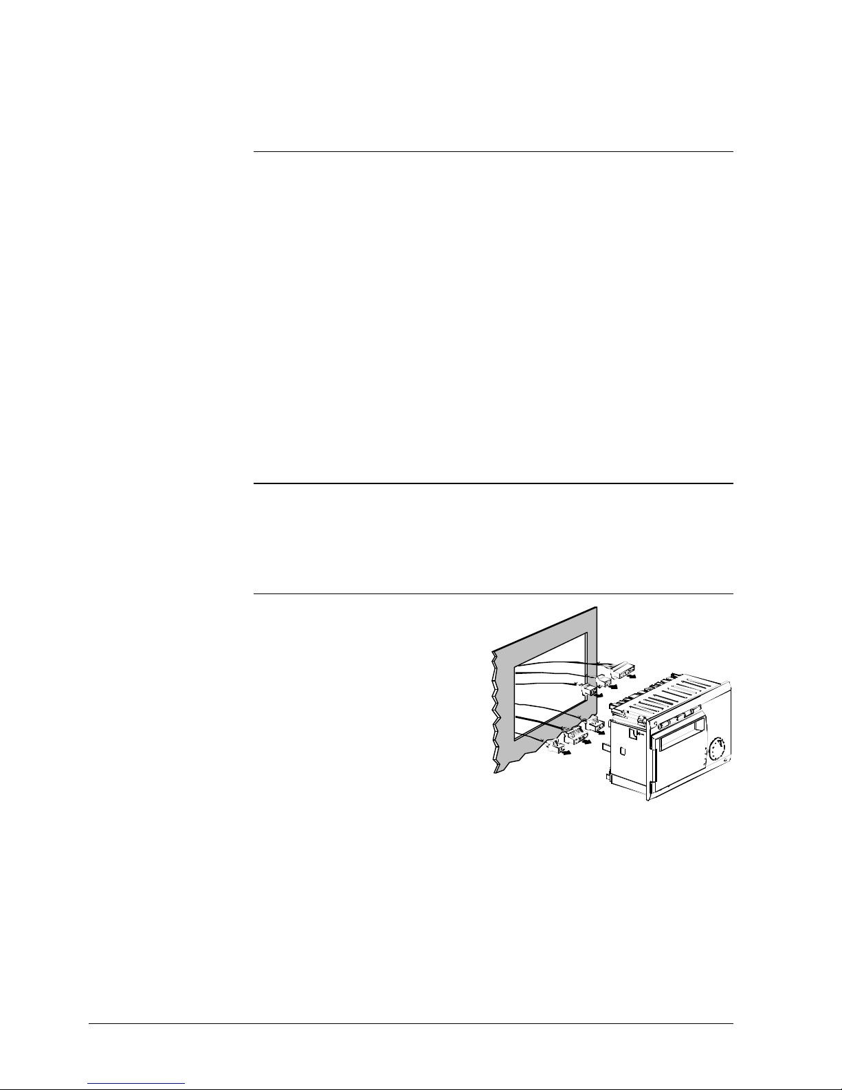
2.1.3 Mounting procedure
• Turn off power supply
• Pull the prefabricated cables through
the cut-out
• Plug the connectors into the
respective sockets at the rear of the
controller
è Note:
The connectors are coded to make
certain they cannot be mixed up.
2373Z05
1. Making the
connections
Page 15

15/218
Siemens Building Technologies Basic Documentation RVA63.242, RVA53.242 CE1P2373E
Landis & Staefa Division Handling 26.03.2001
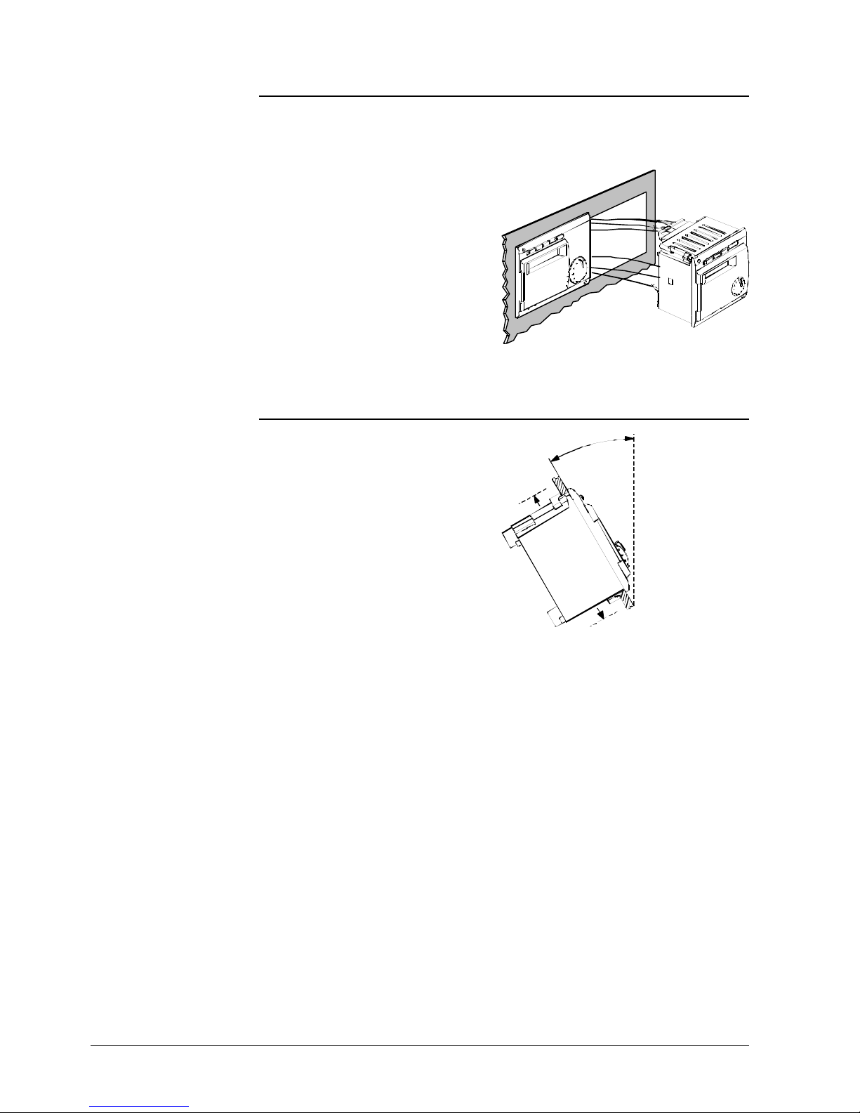
• Check to ensure the fixing levers are
turned inward
• Check to make certain there is
sufficient space between the front
panel and the fixing levers
2373Z06
• Slide the controller into the panel cutout without applying any force
è Note:
Do not use any tools when inserting
the unit into the cut-out. If it does not
fit, check the size of the cut-out and
the position of the fixing levers.
2373Z07
Tighten the 2 screws on the front of the
controller
è Note:
Tighten the screws only slightly,
applying a torque of maximum
20 Ncm.
When tightening the screws, the
fixing levers automatically assume
their correct positions.
2373Z08
2. Check
3. Fitting
4. Fixing
Page 16
16/218
Siemens Building Technologies Basic Documentation RVA63.242, RVA53.242 CE1P2373E
Landis & Staefa Division Handling 26.03.2001
2.1.4 Required cut-out
The controller's mounting dimensions are 91 x 137 mm
Due to the dimensions of the front, however, the standard spacing is 144 mm
The controller can be fitted in front panels of different thicknesses
The mechanical mounting facility makes
it possible to arrange several controllers
in a row in one cut-out. In that case, it is
merely necessary to have a wider panel
cutout.
Also refer to "Dimensions" in Index.
2373Z09
2.1.5 Orientation
To avoid overtemperatures inside the
controller, the inclination may be no
more than 30° and there must be a
clearance of at least 10 mm above and
below the cooling slots.
This allows the controller to emit the
heat generated during operation.
10mm
m
a
x
.
3
0
°
2371Z16
10mm
Dimensions of cut-out
Combination of
controllers
Page 17
17/218
Siemens Building Technologies Basic Documentation RVA63.242, RVA53.242 CE1P2373E
Landis & Staefa Division Handling 26.03.2001
2.2 Electrical installation
2.2.1 Regulations for installation
• Prior to installing the controller, the power supply must be turned off
• The connections for mains and low voltage are separated
• The wiring must be made in compliance with the requirements of safety class II. This
means that sensor and mains cables may not be run in the same duct
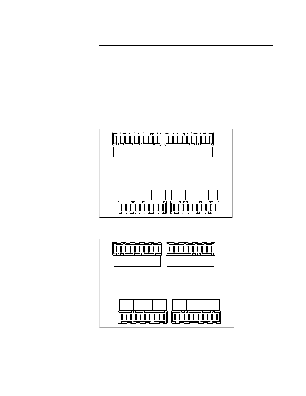
2.2.2 Wiring
When using prefabricated cables with connectors, the electrical installation is very
straightforward, owing to coding.
Rear of controller
Connection terminals of RVA63.242
2373A01
4
M
B8/B6
M
B7
H1
6 5 4 M 2 1 M M
B2B3MB1B9MDA6MBDB
F2
F
N
N
Y1
Y2
F6
Q2
23F234 LF2F45F23
L
F4
K4
F5
K5
E1
F1
K6
3 M 1 4 3 M 1
B31/H2
B41
Q3/Y3
B4
K7
Connection terminals of RVA53.242
2373A10
4
M
B8
M
B7
H1
6 5 4 M 2 1 M M
B2B3MB1B9MDA6
F2
F
N
N
Y1
Y2
F6
Q2
23F234 LF2F45F23
L
F4
K4
F5
K5
E1
F1
K6
3 M 1 4 3 M 1
B31/H2
Q3/Y3
B4
K7
Note
Page 18

18/218
Siemens Building Technologies Basic Documentation RVA63.242, RVA53.242 CE1P2373E
Landis & Staefa Division Handling 26.03.2001
Terminal Terminals Connector Color
– Not used –
– Not used
B4 Buffer storage tank sensor 1 AGP2S.04C yellow
– Not used
M Ground sensors
B8/B6 Flue gas temperature sensor / collector
temperature sensor
B31/H2 D.h.w. temperature sensor 2 / input H2 /
buffer storage tank temperature sensor 2
AGP2S.04G grey
B1 Flow temperature sensor mixing valve
M Ground sensors
B7 Return temperature sensor
H1 Signal input H1 AGP2S.06A white
B2 Boiler temperature sensor 1
B3 D.h.w. temperature sensor / thermostat
M Ground sensors
– Not used
B9 Outside sensor
MD Ground PPS (room unit, BMU) AGP2S.02G blue
A6 PPS (room unit, BMU)
MB Ground bus (LPB) AGP2S.02M violet
DB Data bus (LPB)
Terminal Terminals Connector Color
– Not used –
– Not used
– Not used
– Not used AGP3S.04F orange
K7 Multi-functional output
Q2 Circulating pump mixing heating circuit
F6 Phases Q2 and K7
Y2 Mixing valve CLOSED AGP3S.03K green
Y1 Mixing valve OPEN
F2 Phases Y1 and Y2
Q3/Y3 D.h.w. charging pump / d.h.w. diverting
valve
AGP3S.03B brown
K6 Multi-functional output
F1 Phases K6 and Q3/Y3
E1 Hours run burner stage 1 AGP3S.05D red
K5 Burner stage 2
F5 Phase burner stage 2
K4 Burner stage 1
F4 Phase burner stage 1
L Live AC 230 V (mains connection) AGP3S.02D black
N Neutral (mains connection)
Low voltage side
Mains voltage side
Page 19
19/218
Siemens Building Technologies Basic Documentation RVA63.242, RVA53.242 CE1P2373E
Landis & Staefa Division Handling 26.03.2001
2.3 Commissioning
To commission the controller:
• Make certain that mounting and electrical installation are in compliance with the
relevant requirements
• Make all plant-specific settings as described in section "Parameter settings"
• Reset the attenuated outside temperature
• Make the functional checks
2.3.1 Functional checks
To facilitate commissioning and fault tracing, the controller allows output and input tests
to be made. With these tests, the controller’s inputs and outputs can be checked.
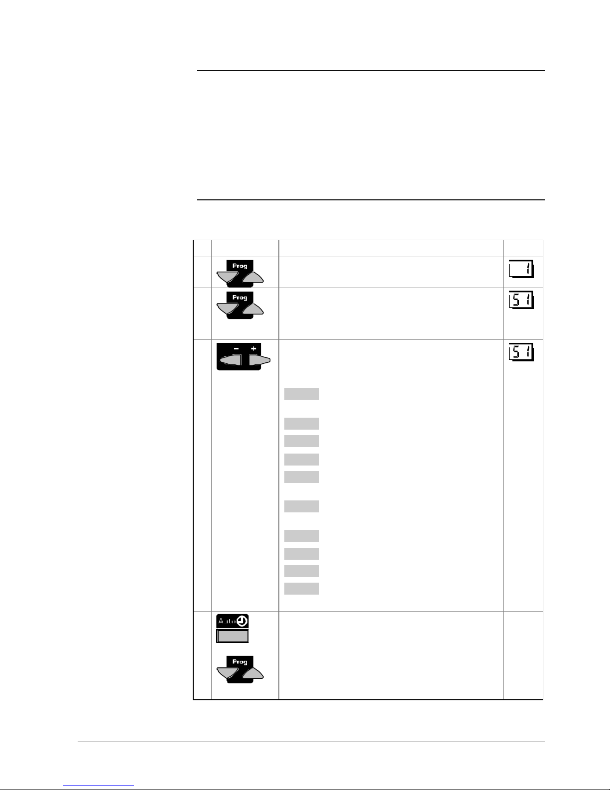
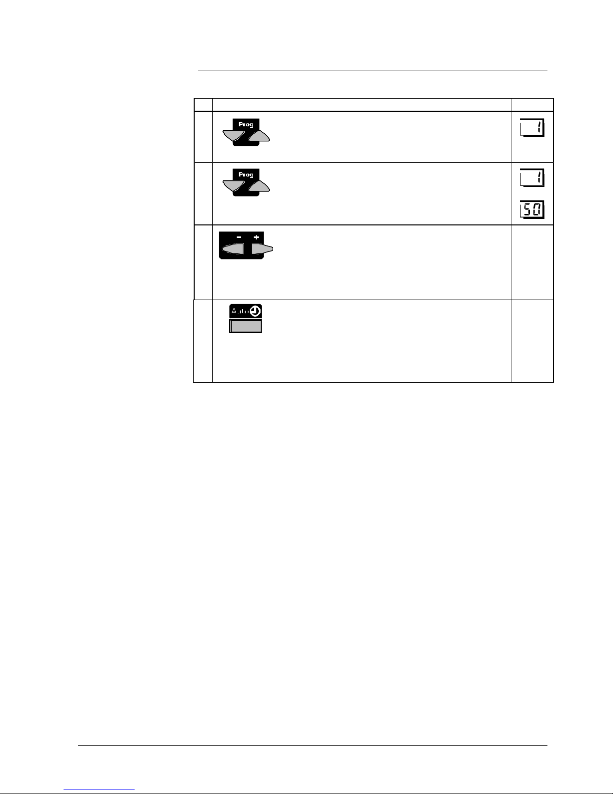
Buttons Explanation Line
1 Press one of the line selection buttons.
This will take you to the programming mode.
2 Press both line selection buttons for at least 3
seconds.
This will take you to the programming mode “Heating
engineer” and, at the same time, to the output test.
3 Press the + or - button repeatedly, which will take you
one test step further:
Test step 0 All outputs are switched according to normal
control operation
Test step 1 All outputs are deactivated
Test step 2 Burner stage 1 (K4) is activated
Test step 3 Burner stages 1 and 2 (K4 + K5) are activated
Test step 4 D.h.w. charging pump / diverting valve (Q3 / Y3) is
activated
Test step 5 Mixing heating circuit / boiler pump (Q2) is
activated
Test step 6 Mixing valve OPEN (Y1) is activated
Test step 7 Mixing valve CLOSED (Y2) is activated
Test step 8 Multi-functional output (K6) is activated
Test step 9 Multi-functional output (K7) is activated
4 By pressing any of the operating mode or line
selection buttons, you leave the programming mode
and thus the output test.
• Note:
If no button is pressed for about 8 minutes, the
controller will automatically return to the operating
mode selected last.
Prerequisites
Output test
Page 20

20/218
Siemens Building Technologies Basic Documentation RVA63.242, RVA53.242 CE1P2373E
Landis & Staefa Division Handling 26.03.2001
b)
c)
2373Z03
a)
a) The pointer below the symbol indicates the output activated
b) The number indicates the current test step
c) The number indicates the selected setting line
Display
Page 21

21/218
Siemens Building Technologies Basic Documentation RVA63.242, RVA53.242 CE1P2373E
Landis & Staefa Division Handling 26.03.2001
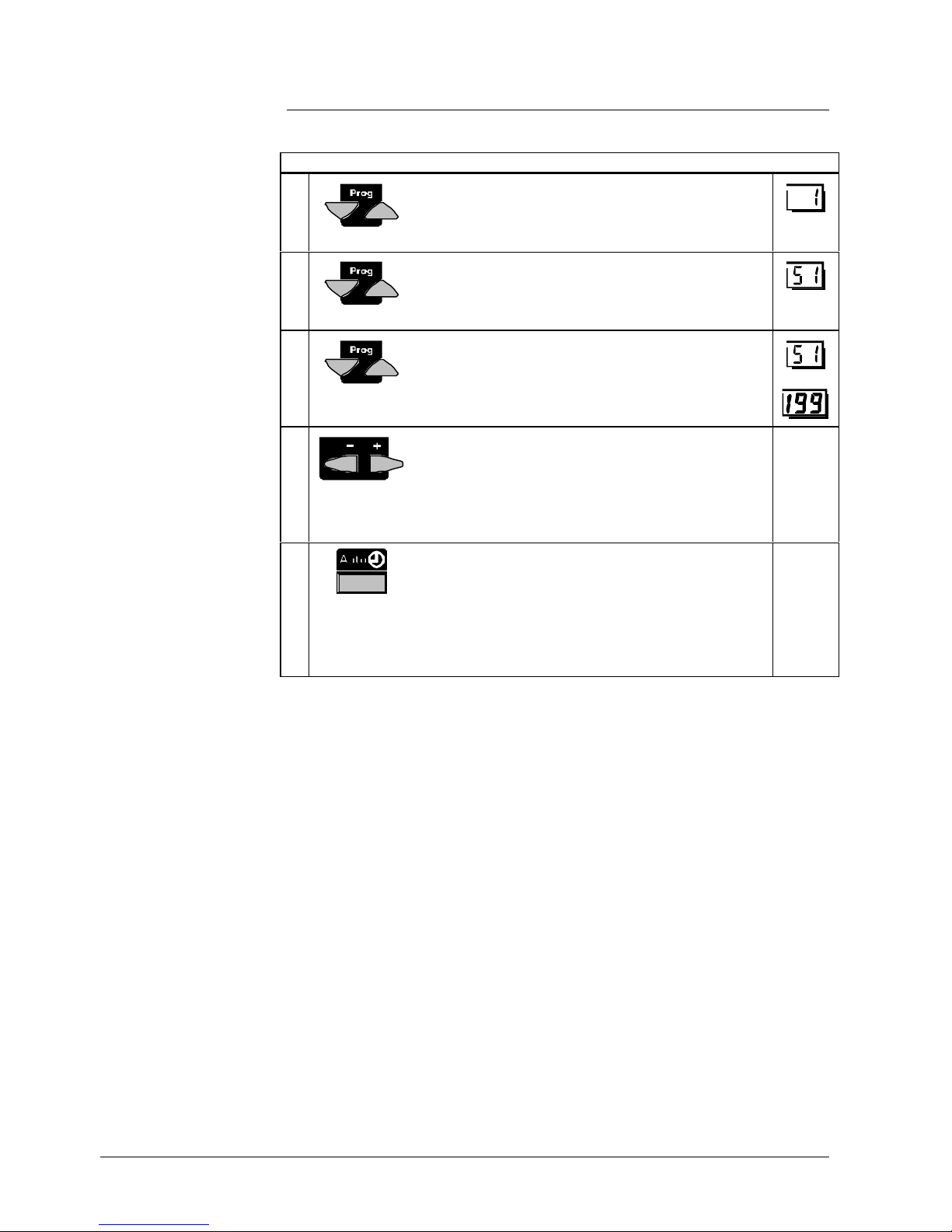
Buttons Explanation Line
1 Press one of the line selection buttons.
This will take you to the programming mode.
2 Press both line selection buttons for at least 3
seconds.
This will take you to the programming mode "Heating
engineer”.
3 Press line selection button UP until you reach line 52.
This will take you to the input test.
4 Press the + or - button repeatedly, which will take you
one test step further:
Test step 0 Display of boiler temperature acquired with sensor
B2
Test step 1 Display of d.h.w. temperature acquired with sensor
B3
Test step 2 Display of input B31/H2/B41
according to the function selected on line 174
[°C or 000 or ---]
Test step 3 Display of flow temperature acquired with sensor
HK1 B1
Test step 4 Display of the outside temperature acquired with
sensor B9
Test step 5 Display of room temperature acquired with sensor
A6
Test step 6 Display of the return temperature acquired with
sensor B7
Test step 7 Display of flue gas /
collector temperature acquired with sensor B8/B6
Test step 8 Buffer temperature 1 acquired with sensor B4
Test step 9 Display of input H1 according to the function
selected on operating line 170 [°C, 000, - - -]
Test step 10 Display of switching status input E1
5 By pressing any of the operating mode buttons, you
leave the programming mode and thus the input test.
• Note:
If no button is pressed for about 8 minutes, the
controller will automatically return to the operating
mode selected last.
Continuous
display
The selected sensor values are updated within a maximum of 5 seconds.
An open-circuit is displayed as – – –.
A short-circuit is displayed as o o o.
Input test
Note
Page 22

22/218
Siemens Building Technologies Basic Documentation RVA63.242, RVA53.242 CE1P2373E
Landis & Staefa Division Handling 26.03.2001
b)
c)
2373Z04
a)
a) The number indicates the current test step
b) Displayed value of the temperature measured
c) The number indicates the selected setting line
Display
Page 23
23/218
Siemens Building Technologies Basic Documentation RVA63.242, RVA53.242 CE1P2373E
Landis & Staefa Division Handling 26.03.2001
2.4 Parameter settings for the end-user
The following settings can be made to meet the individual needs of the end-user.
Buttons Explanation Line
1
Press one of the line selection buttons UP/DOWN.
This will take you directly to the programming mode
"End-user”.
2
Press the line selection buttons to select the required
line.
The parameter list on the next 2 pages contains all
available lines.
• • •
3
Press the + or - button to set the required value.
The setting will be stored as soon as you leave the
programming mode or change to another line.
The parameter list on the next 2 pages contains all
settings that can be made.
4
By pressing any of the operating mode buttons, you
leave the programming mode "End-user”.
• Note:
If no button is pressed for about 8 minutes, the
controller will automatically return to the operating mode
selected last.
Continuous
display
Description
Setting
Page 24

24/218
Siemens Building Technologies Basic Documentation RVA63.242, RVA53.242 CE1P2373E
Landis & Staefa Division Handling 26.03.2001
2.4.1 Overview of end-user parameters
RVA63.242
RVA53.242
Function
Range
Unit
Resolution
Factory
setting
Setting the clock
1 1 Time of day 0...23:59 h / min 1 min 00:00
2 2 Weekday 1...7 Day 1 day 1
3 3 Date (day, month) 01.01...31.12 tt.MM 1 4 4 Year 1999...2099 jjjj 1 -
Time switch program 1
5 5 Pre-selection of weekday
1-7 7-day block
1...7 Individual days
1-7 / 1...7 Day 1 day -
6 6 Switch-on time 1st period - -:- -...24:00 h / min 10 min 06:00
7 7 Switch-off time 1st period - -:- -...24:00 h / min 10 min 22:00
8 8 Switch-on time 2nd period - -:- -...24:00 h / min 10 min - -:- 9 9 Switch-off time 2nd period - -:- -...24:00 h / min 10 min - -:- 10 10 Switch-on time 3rd period - -:- -...24:00 h / min 10 min - -:- 11 11 Switch-off time 3rd period - -:- -...24:00 h / min 10 min - -:- -
Time switch program 2
12 12 Pre-selection of weekday
1-7 7-day block
1...7 Individual days
1-7 / 1...7 Day 1 day -
13 13 Switch-on time 1st period - -:- -...24:00 h / min 10 min 06:00
14 14 Switch-off time 1st period - -:- -...24:00 h / min 10 min 22:00
15 15 Switch-on time 2nd period - -:- -...24:00 h / min 10 min - -:- 16 16 Switch-off time 2nd period - -:- -...24:00 h / min 10 min - -:- 17 17 Switch-on time 3rd period - -:- -...24:00 h / min 10 min - -:- 18 18 Switch-off time 3rd period - -:- -...24:00 h / min 10 min - -:- -
Time switch program 3 (d.h.w.)
19 19 Pre-selection of weekday
1-7 7-day block
1...7 Individual days
1-7 / 1...7 Day 1 day -
20 20 Switch-on time 1st period - -:- -...24:00 h / min 10 min 06:00
21 21 Switch-off time 1st period - -:- -...24:00 h / min 10 min 22:00
22 22 Switch-on time 2nd period - -:- -...24:00 h / min 10 min - -:- 23 23 Switch-off time 2nd period - -:- -...24:00 h / min 10 min - -:- 24 24 Switch-on time 3rd period - -:- -...24:00 h / min 10 min - -:- 25 25 Switch-off time 3rd period - -:- -...24:00 h / min 10 min - -:- -
D.h.w.
26 26 Nominal setpoint of d.h.w. temperature (TBWw)
TBWRw Line 120
TBWmax Line 50 (OEM)
TBWR...TBWmax °C 1 55
Heating circuit
27 27 Reduced room temperature setpoint (TRRw)
heating circuits 1 and 2
TRF Frost protection setpoint of the room temperature,
line 28
TRN Setpoint knob heating circuit
TRF...TRN °C 0.5 16
28 28 Room temperature frost protection setpoint (TRFw)
heating circuits 1 and 2
TRRw Line 27
4...TRRw °C 0.5 10
Page 25

25/218
Siemens Building Technologies Basic Documentation RVA63.242, RVA53.242 CE1P2373E
Landis & Staefa Division Handling 26.03.2001
RVA63.242
RVA53.242
Function
Range
Unit
Resolution
Factory
setting
29 29 Summer / winter changeover temperature heating
circuit 1 (THG1)
8...30 °C 0.5 17
30 30 Heating curve slope HK1 (S1)
- : - - Inactive
2.5...40 Active
- : - - / 2.5...40 - 0.5 15
31 31 Summer / winter changeover temperature heating
circuit 2 (THG2)
8 ... 30 °C 0.5 17
32 32 Heating curve slope HK2 (S2)
-:- - Inactive
2.5...40 Active
-:- - / 2.5...40 - 0.5 15
33 33 Actual value of room temperature (TRx) 0...50 °C 0.5 34 34 Actual value of outside temperature (TAx)
To reset the attenuated outside temperature to TAx, press the +
and - buttons simultaneously for 3 seconds.
-50...+50 °C 0.5 -
Heat source
35 35 Burner hours run stage 1 or BMU (tBR1) 0 ... 65535 h 1 0
36 36 Burner hours run stage 2 (tBR2)
Output K5
0 ... 65535 h 1 0
37 37 Number of burner starts stage 1 0 ... 65535 - 1 0
38 38 Number of burner starts stage 2 0 ... 65535 - 1 0
Standard values
39 39 Standard times for switching programs 1, 2, 3
(lines 6...11, 13...18 and 20...25)
To activate, press the + and - buttons simultaneously for 3
seconds
- - - -
Holidays
40 40 Holiday period HK1+HK2 1...8 - 1 1
41 41 Holiday period HK1+HK2
- -.- - No holiday period programmed
Month, day
To reset the holiday period, press the + and - buttons
simultaneously for 3 seconds.
- - . - -
01.01...31.12
tt.MM 1 -
42 42 End of holiday period HK1+HK2
- -.- - No holiday period programmed
Month, day
To reset the selected holiday period, press the + and - buttons
simultaneously for 3 seconds.
- - . - -
01.01...31.12
tt.MM 1 -
Service
49 49 Indication of BMU error code
0...255 Error code
0...255 - 1 -
50 50 Indication of faults 0...255 - 1 -
Page 26
26/218
Siemens Building Technologies Basic Documentation RVA63.242, RVA53.242 CE1P2373E
Landis & Staefa Division Handling 26.03.2001
2.5 Parameter settings for the heating engineer
Configuration and parameter settings to be made by the heating engineer.
Buttons Explanation Line
1
Press one of the line selection buttons UP/DOWN.
This will take you directly to the programming mode
"End-user”.
2
Press both line selection buttons for at least 3 seconds.
This will take you directly to the programming mode
"Heating engineer”.
3
Press the line selection buttons to select the required
line.
The parameter list on the next 2 pages contains all
available lines.
• • •
4
Press the + or - button to set the required value.
The setting will be stored as soon as you leave the
programming mode or change to another line.
The parameter list on the next 2 pages contains all
settings that can be made.
5
By pressing any of the operating mode buttons you
leave the programming mode "Heating engineer”.
è Note:
If no button is pressed for about 8 minutes, the
controller will automatically return to the operating
mode selected last.
Continuous
display
Description
Setting
Page 27

27/218
Siemens Building Technologies Basic Documentation RVA63.242, RVA53.242 CE1P2373E
Landis & Staefa Division Handling 26.03.2001
1.1.1 Overview of heating engineer parameters
RVA63.242
RVA53.242
Function
Range
Unit
Resolution
Factory
setting
Service values
51 51 Output test
0 Control mode according to the operating state
1 All outputs OFF
2 Burner stage 1 ON K4
3 Burner stages 1 and 2 ON K4 / K5
4 D.h.w. charging pump ON Q3/Y3
D.h.w. diverting valve OPEN Q3 / Y3
5 Heating circuit pump 1 Q2
Boiler pump ON Q2
6 Mixing valve 1 open Y1
7 Mixing valve 2 close Y2
8 Multi-functional output ON K6
9 Mult-functional output ON K7
0...9 - 1 0
52 52 Input test
0 Boiler sensor B2
1 D.h.w. sensor 1 B3
2 D.h.w. sensor 2 B31/H2
Buffer storage tank sensor 2 B31/H2
H2 B31/H2
Flow temperature sensor HK1
4 Outside sensor B9
5 Room sensor A6
6 Return sensor B7
7 Flue gas sensor B8/B6
Collector sensor B8/B6
8 Buffer storage tank sensor 1 B4
9 Display of input H1 H1
10 Display switching status input E1. E1
0...10 - 1 0
53 53 Display of plant type 1...150 - 1 -
Actual values
55 55 Actual value of flow temperature (TVx)
Input B1
0...140 °C 1 -
56 56 Actual value of boiler temperature (TKx)
Input B2/B4
0...140 °C 1 -
57 - Actual value of common flow temperature 0...140 °C 1 58 58 Actual value of cascade return temperature 0 ...140 °C 1 59 59 Actual value 1 of buffer storage tank temperature 0 ...140 °C 1 60 - Actual value 2 of buffer storage tank temperature 0...140 °C 1 61 61 Actual value 1 of d.h.w. temperature (TBWx)
(Higher temperature)
0...140 °C 1 -
62 62 Actual value 2 of d.h.w. temperature (TBWx)
(Lower temperature)
0...140 °C 1 -
63 63 Display of max. flue gas temperature (TGxmax)
To make a reset to the current value, press the + and –
buttons simultaneously for 3 seconds
0...350 °C 1 -
64 - Actual value of collector temperature (B6) 0...350 (Pt1000)
0...230 (Ni1000)
°C 1 -
65 65 Attenuated outside temperature (TAxged) -50...+50 °C 0.5 66 66 Composite outside temperature (Taxgem) -50...+50 °C 0.5 67 - Outside temperature source
- - . - - No signal
00.01...14.16 Address
- -:- / 00.01...14.16
- 1 -
Page 28

28/218
Siemens Building Technologies Basic Documentation RVA63.242, RVA53.242 CE1P2373E
Landis & Staefa Division Handling 26.03.2001
RVA63.242
RVA53.242
Function
Range
Unit
Resolution
Factory
setting
Setpoints
68 68 Display of boiler temperature setpoint 0...140 °C 1 69 - Display of flow temperature setpoint 0...140 °C 1 70 70 Display of d.h.w temperature setpoint 0...140 °C 1 71 71 Display of nominal room temperature setpoint
HK1
Nominal setpoint incl. room unit readjustment
0...35 °C 0.5 -
72 72 Display of nominal room temperature setpoint
Nominal setpoint incl. room unit readjustment
0...35 °C 0.5 -
73 73 Display of setpoint of room temperature HK1
(TRw)
0...35 °C 0.5 -
74 74 Display of setpoint of room temperature HK1
(TRw)
0...35 °C 0.5 -
75 75 Display of setpoint of room temperature HK1
(TRw)
0...140 °C 1 -
76 76 Display of flow temperature setpoint HK2 (TVw) 0...140 °C 1 77 - Floor curing dates HK1
Day
Flow temperature setpoint
0...32
0...95
°C
1 -
Heat source
80 80 Type of heat source
0 No heat generation or PPS-BMU
1 Single-stage burner
2 2-stage burner
2 Modulating burner, 3-position air damper actuator
4
Modulating burner, 2-position air damper actuator
5 Cascade (2 single-stage burners)
0...5 - 1 2
81 81 Min. limitation of boiler temperature (TKmin)
Tkmin
OEM
Line 1 OEM
Tkmax Line 2 OEM
TKmin
OEM
...TKmax °C 1 40
82 82 Extra heating for the bathroom
(output K6 or K7 as heating circuit pump 2)
0 Inactive
1 Active
0 / 1 - 1 0
Configuration of plant
95 95 Pump function output (K6)
0 No function
1 Heating circuit pump
2 System pump after d.h.w.
3 System pump before d.h.w.
4 System pump with external demand
5 D.h.w. circulating pump
6 Electric immersion heater for d.h.w.
7 Solar pump
2)
8 Pump H1
9 Boiler pump
10 Boiler bypass pump
11 Alarm output
0...11 - 1 1
96 96 Pump function output (K7)
0 No function
1 Heating circuit pump
2 D.h.w. circulating pump
3 Electric immersion heater for d.h.w.
4 Solar pump
2)
5 Pump H2
6 Boiler bypass pump
7 Alarm output
0...7 - 1 0
Page 29

29/218
Siemens Building Technologies Basic Documentation RVA63.242, RVA53.242 CE1P2373E
Landis & Staefa Division Handling 26.03.2001
RVA63.242
RVA53.242
Function
Range
Unit
Resolution
Factory
setting
98 - Solar application
0 No solar
1 Solar in d.h.w. storage tank
2 Solar in buffer storage tank
0...2 - 1 0
99 - Sensor input B8/B6
0 Flue gas Pt 1000
1 Collector Ni 1000
2 Collector Pt 1000
0...2 - 1 0
Heating circuit
100 100 Parallel displacement of
heating circuits 1 and 2
-4.5...+4.5 °C (K) 0.5 0.0
101 101 Room influence
0 Inactive
1 Active
0 / 1 - 1 1
102 102 Switching differential of room temperature (SDR)
heating circuits 1 and 2
- - . - Inactive
0.5...4.0 Active
- -:-...4.0 °C (K) 0.5 - -:-
103 103 Operating mode of room unit
0 Acting on heating circuit 1
1 Acting on heating circuit 2
2 Acting on heating circuits 1 and 2
0...2 - 1 0
104 104 Room unit values
0 Acting on heating circuit 1
1 Acting on heating circuit 2
2 Acting on heating circuits 1 and 2
0...2 - 1 0
105 105 Min. limitation of flow temperature setpoint
(TVmin) heating circuit 1
TVmax Line 107
8...TVmax °C 1 8
106 106 Min. limitation of flow temperature setpoint
(TVmin) heating circuit 2
TVmax Line 108
8...TVmax °C 1 8
107 107 Max. limitation of flow temperature setpoint
(TVmax) heating circuit 1
Tvmin Line 105
TVmin...95 °C 1 80
108 108 Max. limitation of flow temperature setpoint
(TVmax) heating circuit 2
Tvmin Line 106
TVmin...95 °C 1 80
109 109 Max. forward shift of optimum start control
0 No forward shift
00:00...06:00 hh:mm 10 min 00:00
110 110 Max. forward shift of optimum start control
0 No forward shift
00:00...06:00 hh:mm 10 min 00:00
113 113 Type of building construction
0 Heavy
1 Light
0 / 1 - 1 1
114 114 Adaption of heating curve HK1+HK2
0 Inactive
1 Active
0 / 1 - 1 1
115 115 Gain of locking signal 0...200 % 1 100
116 - Floor curing HK1
0 Off
1 Functional heating
2 Floor curing heating
3 Functional and floor curing heating
0...3 - 1 0
D.h.w.
Page 30

30/218
Siemens Building Technologies Basic Documentation RVA63.242, RVA53.242 CE1P2373E
Landis & Staefa Division Handling 26.03.2001
RVA63.242
RVA53.242
Function
Range
Unit
Resolution
Factory
setting
120 120 Reduced setpoint of d.h.w. temperature (TBWR)
TBWw Line 26
8...TBWw °C 1 40
121 121 D.h.w. program
0 24 h/day
1 System heating program with forward shift
2 Time switch program 3
0...2 - 1 1
122 122 Switching program selection circulating pump
0 According to time switch program 2
1 According to the d.h.w. program (line 121)
0 / 1 - 1 1
123 - Assignment of d.h.w. heating
0 Local heating circuit
1 All heating circuits in the system
2 All heating circuits in the system
0...2 - 1 2
124 124 D.h.w. charging
0 Once per day with a forward shift of 2.5 hours
1 Several times per day with a 1 h forward shift
0 / 1 - 1 1
125 125 Type of d.h.w. demand
0 Sensor
1 Control thermostat
0 / 1 - 1 0
126 126 Boost of flow temperature setpoint for d.h.w.
heating (UEBW)
0...30 °C (K) 1 16
127 127 D.h.w. priority
0 Absolute (mixing and pump heating circuit)
1 Shifting (mixing and pump heating circuit)
2 None (parallel)
3 Mixing heating circuit (shifted), pump heating
circuit absolute
0...3 - 1 1
128 128 Controlling element for d.h.w.
0 Charging pump
1 Diverting valve
0 / 1 - 1 0
129 - Separate d.h.w. circuit
0 Off
1 ON
0 / 1 - 1 0
Cascade
130 130 Changeover of boiler sequence in a cascade 2 x
single-stage
- - - No automatic changeover (fixed boiler sequence)
10...990
Changeover according to the selected number of
hours
- - - / 10...990 - / hours 10 500
131 131 Release integral for boiler sequence 0...500 K*min 1 200
132 132 Reset integral for sequence 0...500 K*min 1 50
LPB / system
140 - LPB device address
0 Standalone
1...16 Device address (system)
0...16 - 1 0
141 - LPB segment address
0 Heat source segment
1...14 Heat consumption segments
0...14 - 1 0
142 - LPB power supply
0 Off (central bus power supply)
1 Auto (bus power supply via controller)
0 / 1 - 1 1
143 - Display of LPB power supply On / OFF - 145 - Range of action of central changeover
0 In the segment
1 In the system (if segment address = 0)
0 / 1 - 1 1
146 - Automatic summer / winter changeover
0 Local change
1 Central changeover of all heating circuits
0 / 1 - 1 0
Page 31

31/218
Siemens Building Technologies Basic Documentation RVA63.242, RVA53.242 CE1P2373E
Landis & Staefa Division Handling 26.03.2001
RVA63.242
RVA53.242
Function
Range
Unit
Resolution
Factory
setting
147 - Central stand-by switch
1)
0 Off
1 ON
0 / 1 - 1 0
148 - Clock mode
0 Autonomous clock
1 System time with remote adjustment
2 (System time with adjustment)
3 System clock (master)
0...3 - 1 0
150 150 Winter- / summertime changeover 01.01...31.12 tt.MM 1 25.03
151 151 Summer- / wintertime changeover 01.01...31.12 tt.MM 1 25.10
155 155 Display of PPS communication
- - - No communication
0...255 Communication ok
0 0 0 Communication line with a short-circuit
- - - / 0...255 / 0 0 0 - 1 -
Solar / buffer storage tank settings
160 - Temperature differential solar ON (TSdEin) TSdAus...40 °C (K) 0.5 20
161 - Temperature differential solar OFF (TSdAus) 0...TSdEin °C (K) 0.5 8
162 - Temperature level solar charging strategy
- - - Inactive
20...130 Charging level
- - - /20...130 °C (K) 1 - - -
163 - Max. solar charging temperature 20...130 °C (K) 1 80
164 164 Demand for heat with reduced d.h.w. setpoint
0 No (buffer storage tank)
1 Yes
0 / 1 - 1 1
Multi-functional inputs (H1) (H2/B31/B41)
170 170 Input H1
0 Changeover of operating mode of all HK and
d.h.w.
1 Changeover of operating mode of all HK
2 Min. flow temperature setpoint (TVHw)
3 Heat generation lock
4 Demand for heat DC 0...10 V
0...4 - 1 0
171 171 Min. setpoint of flow temperature contact H
(TVHw)
...TKmax Line 2 OEM
8...TKmax °C 1 70
172 172 Max. value of heat demand signal (DC 0...10 V)H15...130 °C 1 100
173 173 Operating action contacts H1 and H2
0 N.C.
1 N.O.
0 / 1 - 1 1
174 174 Input B31/H2/B41
0 D.h.w. temperature sensor 2
1 Min. flow temperature setpoint (TVHw)
2 Heat generation lock
3 Buffer temperature sensor 2
0...3 - 1 0
1)
This line is active only if the unit is addressed as the heat generation master. Also refer
to "LPB device address" in Index.
2)
This setting is not integrated for RVA53...
Page 32

32/218
Siemens Building Technologies Basic Documentation RVA63.242, RVA53.242 CE1P2373E
Landis & Staefa Division Handling 26.03.2001
2.6 Parameter settings for the OEM
Boiler-specific settings and protective functions for the boiler manufacturer.
Buttons Explanation Line
1
Press one of the line selection buttons UP/DOWN.
This will take you directly to the programming mode
"End-user”.
2
9 s
Press both line selection buttons for at least 9 seconds.
A special display for entering the code will appear.
3 CODE Press buttons and to enter the required
combination of the access code.
If the combination of buttons is correct, you reach the
programming mode “OEM”.
è Wrong code:
If the code has been entered incorrectly, the display will
change to the "Parameter settings for the heating
engineer”.
4
Press the line selection buttons to select the required
line.
The parameter list on the next 2 pages contains all
available lines.
• • •
5 Press the + or - button to set the required value.
The setting will be stored as soon as you leave the
programming mode or change to another line.
The parameter list on the next 2 pages contains all
settings that can be made.
6 By pressing any of the operating mode buttons you leave
the programming mode “OEM”.
è Note:
If no button is pressed for about 8 minutes, the controller
will automatically return to the operating mode selected
last.
Continu
ous
display
2373Z19
Whether correct or incorrect, each push of a button will be adopted as a digit of the
code. As a confirmation, the respective digit changes to 1.
Description
Setting
Example
Page 33

33/218
Siemens Building Technologies Basic Documentation RVA63.242, RVA53.242 CE1P2373E
Landis & Staefa Division Handling 26.03.2001
2.6.1 Overview of OEM parameters
RVA63.242
RVA53.242
Function
Range
Unit
Resolution
Factory
setting
Heat source
1 1 Min. limitation of boiler temperature OEM
(TKmin
OEM
)
Tkmin Line 81
8...TKmin °C 1 40
2 2 Max. limitation of boiler temperature (TKmax)
Tkmin Line 81
TKmin...120 °C 1 80
3 3 Switching differential of boiler temperature 0...20 °C (K) 1 8
4 4 Min. limitation of burner running time 0...10 min 1 4
5 5 Release limit (integral) of burner stage 2 0...500 °C (K) min 1 50
6 6 Reset limit (integral) of burner stage 2 0...500 °C (K) min 1 10
8 8 Pump overrun time
(after burner OFF)
0...20 min 1 5
9 9 Operating mode of boiler
0 Continuous mode: without extended burner
running time
1 Automatic mode: without extended burner
running time
2 Automatic mode: with extended burner
running time
0...2 - 1 1
10 10 Protective boiler start-up
0 No
1 Yes
0 / 1 - 1 1
12 12 Control of boiler pump
0 Max. temperature requisition
1 Parallel to burner operation
0 / 1 - 1 0
13 13 Air damper running time (s) 7.5...480 s 60
14 14 Proportional band (Xp) 1...200 °C (K) 1 20
15 15 Integral action time (Tn) 10...500 s 1 150
16 16 Derivative action time (Tv) 0...30 s 0.25 4.5
17 17 Switching differential air damper actuator 0...20 °C (K) 1 2
20 20 Maintained boiler return temperature with mixing
valve
0 Inactive
1 Active
0 / 1 - 1 0
21 21 Maintained boiler return temperature with
consumer influence
0 / 1 - 1 1
22 22 Min. limitation of boiler return temperature 8...95 °C 1 8
23 23 Switching differential of bypass pump (SDBP) 0...20 °C (K) 1 6
24 24 Control of bypass pump
0 Parallel to burner operation
1 According to the boiler return temperature
0 / 1 - 1 0
Heating circuit
30 30 Boost of flow temperature setpoint mixing valve
(UEM)
0...50 °C (K) 1 10
31 31 Gain factor of room influence (KORR) 0...20 - 1 4
32 32 Constant for quick setback and optimum start
control (KON)
0...20 - 1 2
33 33 Boost of the room temperature setpoint (DTRSA)
(with boost heating)
0...20 °C (K) 1 5
Page 34

34/218
Siemens Building Technologies Basic Documentation RVA63.242, RVA53.242 CE1P2373E
Landis & Staefa Division Handling 26.03.2001
RVA63.242
RVA53.242
Function
Range
Unit
Resolution
Factory
setting
34 34 Frost protection for the plant
0 Inactive
1 Active
0 / 1 - 1 1
35 35 Control mode of actuator
0 2-position (Y1)
1 3-position (Y1,Y2)
0 / 1 - 1 1
36 36 Switching differential of actuator
For 2-position mixing valve
0...20 °C (K) 1 2
37 37 Overtemperature protection for the pump heating
circuit
0 Inactive
1 Active
0 / 1 - 1 1
38 38 Heat gains (Tf) -2...+4 °C 0.1 0
39 39 Adaption sensitivity 1 (ZAF1) 1...15 - 1 15
40 40 Adaption sensitivity 2 (ZAF2) 1...15 - 1 15
41 41 P-band mixing valve (Xp) 1...100 °C (K) 1 32
42 42 Integral action time mixing valve (Tn) 10...873 s 1 120
43 43 Actuator running time mixing valve 30...873 s 1 120
D.h.w.
50 50 Max. nominal setpoint of d.h.w. temperature
(TBWmax)
8...80 °C 1 60
51 51 Switching differential of d.h.w. temperature
(SDBW)
0...20 °C (K) 1 5
52 52 Legionella function
0 Inactive
1 Active
0 / 1 - 1 1
53 53 Setpoint of legionella function 8...95 °C 1 65
54 54 Discharching protection during d.h.w. heating
0 No
1 Continuously
2 Partly
0...2 - 1 2
Service
90 90 Continuous display
0 Weekday / time of day
1 Actual value of boiler temperature
0 / 1 - 1 0
91 91 Software version 00.0...99.0 - 1 92 92 Device operating hours 0...500000 h 1 0
Page 35

35/218
Siemens Building Technologies Basic Documentation RVA63.242, RVA53.242 CE1P2373E
Landis & Staefa Division Handling 26.03.2001
2.7 Operation
Operating instructions are inserted at the rear of the unit's front cover.
2.7.1 Operating elements
BUS
ECO
2373Z01
1
4
6
3
2
5
7 8
9
Operating element Function
Room temperature setpoint knob Adjustment of room temperature setpoint
Setting buttons Parameter settings
Line selection buttons Parameter settings
Display
Display of actual values and settings
Operating mode buttons heating
circuit
Operating mode changes to:
Automatic operation
Continuous operation
Stand-by
Operating mode button d.h.w. D.h.w. heating ON / OFF
Function button with LED for
manual operation
Activation of manual operation
Function button with LED for
chimney sweep
Activation of chimney sweep function
Connection facility for PC tool
Diagnostics and service
Introduction
Page 36

36/218
Siemens Building Technologies Basic Documentation RVA63.242, RVA53.242 CE1P2373E
Landis & Staefa Division Handling 26.03.2001
a)
b)
c)
BUS
ECO
2373Z02
d)
a) Symbols - indication of operating state with the black pointers
b) Display during normal control mode or when making settings
c) Programming line when making settings
d) Heating program of current day
Display
Page 37

37/218
Siemens Building Technologies Basic Documentation RVA63.242, RVA53.242 CE1P2373E
Landis & Staefa Division Handling 26.03.2001
2.8 Operational faults
No display on the controller:
• Is the heating plant's main switch turned on?
• Are the fuses in order?
• Check the wiring
Heating control does not function. There is no display of the time of day, or the
time displayed is incorrect
• Check fuses of the plant
• Make a reset: Isolate controller from the mains supply for about 5 seconds (e.g. turn
off the boiler's main switch for 5 seconds)
• Set the correct time of day on the controller (operating line 1)
• Check the time of day on the clock time master if the controller is used in a system
Controlling element does not open / close or does not operate correctly.
• Manual lever of controlling element may not be engaged
• Wiring to the controlling element interrupted (output test)
• Check wiring of the sensors (input test)
• Quick setback or the automatic 24-hour heating limit is active
• Check the settings
Heating circuit pump does not run
• Is the right type of plant displayed (setting line 53)?
• Check wiring and fuse (output test)
• Check wiring of the sensors (input test)
• Check the settings
Burner does not switch on
• Press burner's reset button
• Check the fuses
• Wiring to the controlling element interrupted (output test)
• Check the electromechanical control thermostat (TR) and the manual reset safety
limit thermostat (STB)
• Quick setback or automatic 24-hour heating limit is active
• Check wiring of the boiler temperature sensor (input test)
Pump does not run
• Check wiring and fuse (output test)
• Check wiring of the sensors (input test)
D.h.w. is not being heated
• Has the button for d.h.w. heating been activated?
• Check setting of the electromechanical control thermostat (TR) installed on the
boiler. It must be above the TKmax setting
• Check setpoint of the d.h.w. temperature
• Check actual value of the d.h.w. temperature
• Check if d.h.w. heating is released
Page 38

38/218
Siemens Building Technologies Basic Documentation RVA63.242, RVA53.242 CE1P2373E
Landis & Staefa Division Handling 26.03.2001
• Check wiring and fuse of the charging pump (input test)
• Check wiring of the d.h.w. temperature sensor (output test)
The room temperature does not agree with the required temperature level:
• Check the room temperature setpoints
• Is the required operating mode indicated?
• Is automatic operation overridden by the room unit?
• Are weekday, time of day and the displayed heating program correct?
• Has the heating curve slope been correctly set?
• Check wiring of outside sensor
Heating plant does not function properly
• Check all parameters based on the setting instructions "Heating engineer" and the
operating instructions "End-user"
• Carry out the input testCarry out the output testCheck the electromechanical control
thermostat (TR) and the manual reset safety limit thermostat (STB)
Frost protection for the plant does not function at all, or does not function
correctly
• Check correct functioning of the burner
• Check correct functioning of the pumps
• Frost protection for the plant in the case of pump heating circuits with active room
temperature limitation
Quick setback or boost heating does not function
• Check settings made on the heating engineer's level
• Check the sensor connected to A6 (input test)
Fault status signal; display shows "ER"
• For cause of error, refer to section "Parameter settings for end-user" on line 50
Page 39

39/218
Siemens Building Technologies Basic Documentation RVA63.242, RVA53.242 CE1P2373E
Landis & Staefa Division Description of end-user settings 26.03.2001
3 Description of end-user settings
User interface
3.1 Operating modes of heating circuit
Straightforward and direct selection of heating circuit operating modes.
The control provides 3 different heating circuit operating modes that can be directly
selected as required.
Select the required operating mode by pressing the respective operating mode button.
It is located on the controller front for direct access by the user.
The d.h.w. operating mode will not be affected by the selected heating circuit operating
mode, with the exception of the holiday function and when the remote telephone switch
is activated
Operating
mode
Designation Effect of selected operating mode
Automatic
operation
• Heating according to the time program
(lines 5 to 11)
• Temperature setpoints according to the heating
program
• Protective functions active
• Changeover on the room unit active
• Automatic summer / winter changeover (ECO
functions) and automatic 24-hour heating limit
active
Continuous
operation
• Heating mode with no time program
• Temperature adjustment with the setpoint knob
• Protective functions active
• Changeover on room unit inactive
• Automatic summer / winter changeover (ECO
functions) inactive
Stand-by • Heating OFF
• Temperature according to frost protection
• Protective functions active
• Changeover on room unit inactive
• Automatic summer / winter changeover (ECO
functions) and automatic 24-hour heating limit
active
Benefit
Description
Setting
Note
Effect
Page 40

40/218
Siemens Building Technologies Basic Documentation RVA63.242, RVA53.242 CE1P2373E
Landis & Staefa Division Description of end-user settings 26.03.2001
The selected operating mode is indicated by illuminated buttons. A number of functions
can cause the displayed selection to change. The following table shows the possible
statuses. The following table shows the possible statuses:
Function Effect on button and meaning
Heat generation lock
Line 170 = 3 or 174 = 2
• Selected HC operating mode button flashes when
contact H1 or H2 is closed
• D.h.w. operating mode button flashes when
switched on
Changeover of operating
mode
Line 170 = 0
• HC operating mode button flashes when contact
H1 is closed
• D.h.w. operating mode button flashes when switched
on
Changeover of operating
mode
Line 170 = 1
• Selected HC operating mode button flashes when
contact H1 is closed
• D.h.w. operating mode button will not be affected
Minimum setpoint of flow
temperature
Line 170 = 2 or 174 = 1
• Selected HC operating mode button flashes when
contact H1 or H2 is closed
• D.h.w. operating mode button will not be affected
Heat demand DC 0…10 V
Line 170 = 4
• Selected HC operating mode button flashes when
H1 demand is valid
• D.h.w. operating mode button will not be affected
Central stand-by switch
Line 147 = 1
• HC operating mode flashes
• D.h.w. operating mode button will not be affected
Settings on the room unit
Occupancy button • HC operating mode flashes when occupancy
button is active.
• D.h.w. operating mode button will not be affected
Holiday function • HC operating mode flashes when holiday
function is active
• Depending on the setting made on line 123, the d.h.w.
operating mode button flashes when switched on
Changeover of the operating mode on the room unit is active only when the controller is
in automatic mode .
The room temperature is transmitted to the controller via PPS, independent of the
selected operating mode.
Illuminated buttons
Settings on the
controller
Influence of room unit
Page 41

41/218
Siemens Building Technologies Basic Documentation RVA63.242, RVA53.242 CE1P2373E
Landis & Staefa Division Description of end-user settings 26.03.2001
3.2 Operating mode of d.h.w. heating
Selection of d.h.w. heating mode independent of heating operation.
Selection is made directly on the user interface
.
D.h.w. heating is selected by pressing the respective button on the controller's user
interface.
By pressing the respective button, d.h.w. heating is switched on or off.
• D.h.w. heating OFF - button dark.
D.h.w. is not being heated. Frost protection remains active, however, and prevents
the storage tank temperature from falling below a certain level
• D.h.w. heating ON - button illuminated.
The d.h.w. is heated according to the settings made
The following settings affect d.h.w. heating and must be checked to ensure proper
functioning:
Setting Setting
• Time switch program 3 19-25
• Nominal setpoint of d.h.w. temperature 26
• Summer / winter changeover HC1 and HC2 (when using an
electric immersion heater)
29, 31
• Assignment of d.h.w. heating 123
• Reduced setpoint of the d.h.w. temperature 120
• D.h.w. heating program 121
• D.h.w. heating 124
• Type of d.h.w. demand 125
Benefits
Setting
Effect
Required settings
Page 42

42/218
Siemens Building Technologies Basic Documentation RVA63.242, RVA53.242 CE1P2373E
Landis & Staefa Division Description of end-user settings 26.03.2001
3.3 Nominal room temperature setpoint
Straightforward and direct setting of the required nominal room temperature setpoint.
The heating system uses 3 different setpoints that can be adjusted:
The nominal room temperature setpoint described here
The reduced room temperature setpoint (setting on line 27)
The frost protection setpoint of the room temperature (setting on line 28)
The nominal room temperature setpoint is preadjusted with the
setpoint knob. It is located on the controller front for direct
access by the user.
Setting range Unit Factory setting
8...26 °C 20
0 2 4 6 8 10 12 14 16 18 20 22 24 26
°C
2373Z10
Room temperature setpoint setting ranges
27 Setting "Reduced room temperature setpoint”
28 Setting "Frost protection setpoint of the room temperature”
When the nominal room temperature setpoint is active, the rooms will be heated
according to the adjustment made with the setpoint knob.
Effect in the various operating modes:
Operating mode Effect of knob adjustment
Adjustment acts on the heating periods
Adjustment acts continuously
Adjustment has no effect
The adjustment made with the setpoint knob has priority over the reduced room
temperature setpoint entered (line 27). Especially in a situation when the adjustment
made with the knob is lower.
During the heating periods, the nominal room temperature setpoint is maintained. The
heating periods are in accordance with the settings made on lines 6 through 11 and 13
through 18.
Benefit
Description
Setting
Effect of temperature
setting
Note
Example
Page 43

43/218
Siemens Building Technologies Basic Documentation RVA63.242, RVA53.242 CE1P2373E
Landis & Staefa Division Description of end-user settings 26.03.2001
0 2 4 6 8 10 12 14 16 18 20 22 24
h
Mo
...
So
2373Z11
3.3.1 Temperature adjustment via room unit
Temperature adjustment or readjustment via a room unit is active only when, on the
controller, automatic mode has been selected!
Adjustment made with the controller’s setpoint knob
= controller's nominal room temperature setpoint
The QAA50 room unit has a knob for readjusting the setpoint in a + / - range. The
readjustment is added to the actual setpoint adjusted with the controller’s setpoint knob.
Adjustment made with the controller’s setpoint knob
+ readjustment made on the room unit (± 3 °C)
= controller's nominal room temperature setpoint
Adjustment made with the controller’s setpoint knob 20 °C
Adjustment made with the controller’s setpoint knob + 2 °C
Resulting setpoint 22 °C
The QAA70 room unit has an absolute setpoint adjustment using a line, which replaces
the setpoint adjusted with the controller’s setpoint knob, provided automatic mode has
been selected on the controller.
In addition, the QAA70 has a knob for readjusting the setpoint in a + / - range. The
readjustment is added to the actual setpoint adjusted with the controller’s setpoint knob.
Setpoint programmed with the room unit
+ readjustment made on the room unit (± 3 °C)
= controller's nominal room temperature setpoint
Adjustment made with the controller’s setpoint knob
(inactive)
22 °C
Setpoint adjustment on the room unit’s line 19 °C
Adjustment made with the controller’s setpoint knob + 2 °C
Resulting setpoint 21 °C
Without room unit
QAA50
Example:
QAA70
Example:
Page 44

44/218
Siemens Building Technologies Basic Documentation RVA63.242, RVA53.242 CE1P2373E
Landis & Staefa Division Description of end-user settings 26.03.2001
3.4 Chimney sweep
At the touch of a button, the plant is ready for making flue gas measurements.
A function designed specifically for carrying out periodic flue gas measurements.
Activation: The chimney sweep function is activated by pressing this button. It is
accessible only when the cover of the controller is open
Deactivation: By pressing one of the operating mode or function buttons
By pressing again the chimney sweep button
Automatically after one hour
By selecting a number in the output test
During the time the chimney sweep function is activated, the heat output can be
increased or decreased by pressing the + / - buttons.
• With multi-stage burner:
The second burner stage can be switched on or off.
• When leaving the function, the controller will automatically return to the operating
mode previously selected
When the LED in the chimney sweep button is lit, the chimney sweep function is
active.
Multistage burner: Burner stages 1 and 2 will be switched on
Modulating burner Maximum heat output
2 x 1 cascade: Both burners will be switched on
BMU The chimney sweep button has no effect. But the forced
signals will be generated as described below if the chimney
sweep function on the BMU is activated
The boiler's switching differential will not be taken into consideration. To ensure
continuous burner operation, the only switch-off point used is the boiler temperature's
maximum limitation (TKmax).
First, all connected loads will be locked to ensure the boiler temperature will reach the
setpoint of 64 °C as quickly as possible.
When the minimum temperature of 64 °C is attained, the available heating circuits are
switched on one by one, using a dummy load, to make sure the heat generated by the
boiler is drawn off so that the burner will remain in operation.
In the case of a BMU, the loads will immediately be released.
2373Z20
Benefit
Description
Setting
Adaption of output
Notes
LED
Effect
Multi-stage burner
BMU
Display
Page 45

45/218
Siemens Building Technologies Basic Documentation RVA63.242, RVA53.242 CE1P2373E
Landis & Staefa Division Description of end-user settings 26.03.2001
3.5 Manual operation
Manual heating operation in case the control system fails.
Manual operation is an operating mode in which all required plant components must be
manually adjusted and monitored. The controller's control functions have no more
impact on the relays.
The required boiler temperature setpoint must be manually adjusted on the boiler's
control thermostat. The boiler temperature is displayed on setting line 56.
The temperature of the heating circuits can be adjusted with the mixing valve, which
must also be set to manual operation. The room temperature is still displayed on setting
line 33.
Activation: Manual operation is activated by pressing this button. It is accessible
only when the cover of the controller is open
Deactivation: • By pressing one of the operating mode buttons
• By pressing again the manual operation button
When deactivating the function, the controller will automatically return to the operating
mode previously selected.
As soon as manual operation is activated, the following values are used for the heat
demand:
For space heating:
Maximum limitation of flow temperature setpoint (lines 107 and 108).
For the d.h.w.:
Nominal setpoint of d.h.w. temperature (line 26) + setpoint boost of d.h.w. flow
temperature (line 126).
For the minimum flow temperature setpoint and heat demand DC 0…10 V:
Minimum setpoint of the flow temperature, contact H (line 171).
The outputs will be switched to the following states:
Output Terminals State
Burner stages 1 and 2 K4, K5 ON
Heating circuit pump Q2 ON
D.h.w. charging pump
D.h.w. diverting valve
Q3
Y3
ON
OFF
Mixing valve outputs Y1 / Y2 OFF (de-energized)
1)
Multi-functional output K6 / K7 2 = ON
2)
1)
With maintained return temperature with the mixing valve, Y1 will be controlled for a period of time that
equals 5 times the set valve running time. Then, Y1 is de-energized.
2)
Except with the settings of the multifunctional outputs solar, alarm output and modulating burner (only K7).
In these cases, K6/K7 are OFF.
The following functions are no longer active in manual operation:
maximum limitation of the boiler temperature:
Maintained return temperature with mixing valve
2373Z21
Benefit
Description
Boiler temperature
Room temperature
Setting
Note
Effect
Note
Display
Page 46

46/218
Siemens Building Technologies Basic Documentation RVA63.242, RVA53.242 CE1P2373E
Landis & Staefa Division Description of end-user settings 26.03.2001
Setting the clock
Automatic changeover from summer- to wintertime, and vice versa.
Fast and easy-to-understand time settings.
To ensure proper operation of the heating program, the 24-hour time switch with the
time of day and weekday must be correctly set.
Between setting of date (line 3) and setting of weekday (line 2) there is no link. This
means that when the set date falls on a Wednesday, for example, Wednesday as a
weekday must also be set.
Automatic summer- / wintertime changeover adapts the time of day automatically. Also
refer to "summer- / wintertime" in Index.
The time of day can be set from a remote location via the bus system, provided clock
operation is appropriately set. Also refer to "clock mode" in Index.
3.6 Time of day
Setting range Unit
00:00...23:59 Hour : Minute
The controller's clock time is set in agreement with the correct time. This setting is
important to make certain the controller’s heating program will operate correctly.
During the setting procedure, the clock continues to run.
Each time the + or - button is pressed, the seconds are reset to zero.
3.7 Weekday
Setting range Unit
1...7 Day
The time switch will be set to the selected weekday. This setting is important to make
certain the controller’s heating program will operate correctly.
1 = Monday
2 = Tuesday
3 = Wednesday
4 = Thursday
5 = Friday
6 = Saturday
7 = Sunday
Benefits
Description
Note
Summer- / wintertime
System time
Setting
Effect
Notes
Setting
Effect
Weekday table
Page 47

47/218
Siemens Building Technologies Basic Documentation RVA63.242, RVA53.242 CE1P2373E
Landis & Staefa Division Description of end-user settings 26.03.2001
3.8 Date (day, month)
Setting range Unit
01:01...31:12 Day. Month
Day and month of the controller will be based on this setting. This setting of date is
important to make certain the controller’s holiday program and summer- / wintertime
changeover will operate correctly.
3.9 Year
Setting range Unit
1999...2099 Year
The year of the controller will be based on this setting. This setting of year is important
to make certain the controller’s holiday program and summer- / wintertime changeover
will operate correctly.
Setting
Effect
Setting
Effect
Page 48

48/218
Siemens Building Technologies Basic Documentation RVA63.242, RVA53.242 CE1P2373E
Landis & Staefa Division Description of end-user settings 26.03.2001
Time switch program 1
The heating system operates only if there is demand for heat.
The user can set the heating periods to suit his lifestyle.
Energy can be saved by making adequate use of the heating program.
The time switch program consists of the switching times to be entered for the weekdays
or the 7-day block. The controller has 3 time switch programs that function
independently of one another.
Time switch program 1 is always used with heating circuit 1.
3.10 Preselection of weekday for time switch
program 1
This is a preselection of the weekdays or of the 7-day block to set the switching times
for time switch program 1.
The heating program thus set becomes active when selecting automatic mode .
Setting range Unit
1-7
1...7
7-day block
Individual days
This setting must be made before the switching times are entered!
For every day on which other switching times shall apply, preselection of the individual
day with subsequent entry of the switching times must be repeated.
This setting is used to select either the whole week (1-7) or individual days (1...7).
7-day block
Entry of the switching times from line 6 to 11 is identical for every day from Monday
through Sunday.
Example:
0 2 4 6 8 10 12 14 16 18 20 22 24
h
Mo
...
So
2373Z11
Switching time for nominal setpoint
Switching time for reduced setpoint
Individual days
The setting of the switching times from line 6 through 11 is entered only for the
individual day selected here.
è Tip
First, choose the 7-day block (1-7) to enter the switching times that apply to the
majority of days; then, select the individual days (1...7) to make the required
adjustments.
Benefits
Description
Description
Setting
Important
Effect
Entry of 1-7
Entry of 1...7
Page 49

49/218
Siemens Building Technologies Basic Documentation RVA63.242, RVA53.242 CE1P2373E
Landis & Staefa Division Description of end-user settings 26.03.2001
0 2 4 6 8 10 12 14 16 18 20 22 24
h
Sa
Mo
Di
Mi
Do
Fr
So
2373Z12
Example:
Page 50

50/218
Siemens Building Technologies Basic Documentation RVA63.242, RVA53.242 CE1P2373E
Landis & Staefa Division Description of end-user settings 26.03.2001
3.11 Switching times of time switch program 1
This is the setting of the switching times of time switch program at which the
temperature setpoints for the relevant heating circuit will change.
The heating program thus set becomes active with automatic mode .
Setting range Unit Factory setting
- -:- -...24:00 h : min See "Program overview"
below
First, select the weekday for which the switching times shall be entered!
The controller makes a final check to ensure the entries have been made in the correct
order.
At the times entered, the program will switch to the respective temperature setpoints.
The table below shows at what times the setpoints will be activated.
Entry:
– – : – – Switching point inactive.
00:00...24:00At the time entered, heating to the respective temperature is ensured.
Line Switching point Temperature setpoint Standard
Switch-on time period 1 Setpoint of knob 06:00
Switch-off time period 1
Reduced setpoint
22:00
Switch-on time period 2 Setpoint of knob – – : – –
Switch-off time period 2
Reduced setpoint
– – : – –
Switch-on time period 3 Setpoint of knob – – : – –
Switch-off time period 3
Reduced setpoint
– – : – –
In AUTO mode, the time switch program can be set on both the controller (as described
above) and on the QAA70 room unit. It is always the last action that is active.
Description
Setting
• • •
Important
Note
Effect
Program overview
Effect of room unit
Page 51

51/218
Siemens Building Technologies Basic Documentation RVA63.242, RVA53.242 CE1P2373E
Landis & Staefa Division Description of end-user settings 26.03.2001
Time switch program 2
The heating system operates only if there is demand for heat.
The user can set the heating periods to suit his lifestyle.
Energy can be saved by making adequate use of the heating program.
The time switch program consists of the switching times to be entered for the weekdays
or the 7-day block. The controller has 3 time switch programs that function
independently of one another.
Time switch program 2 is always used with heating circuit 2 or the d.h.w. circulating
pump.
3.12 Preselection of weekday for time switch
program 2
This is a preselection of the weekdays or the 7-day block to set the switching times for
time switch program 2.
The heating program thus set becomes active with automatic mode .
Setting range Unit
1-7
1...7
7-day block
Individual days
• This setting must be made before the switching times are entered!
• For every day on which other switching times shall apply, preselection of the
individual day with subsequent entry of the switching times must be repeated
This setting is used to select either the whole week (1-7) or individual days (1...7).
Entry:
1-7 7-day block:
Entry of switching times on lines 13 through 18 is identical for every day from
Monday through Sunday.
1...7 Individual days:
Entry of switching times on lines 13 through 18 is made only for the individual
day selected here.
For an example, refer to the graph in the previous section “Time switch program 1".
Benefits
Description
Description
Setting
Important
Effect
Example:
Page 52

52/218
Siemens Building Technologies Basic Documentation RVA63.242, RVA53.242 CE1P2373E
Landis & Staefa Division Description of end-user settings 26.03.2001
3.13 Switching times of time switch program 2
This is the setting of the switching times for time switch program 2 at which the
temperature setpoints for heating circuit 2 will change.
The heating program thus set becomes active with automatic mode .
Setting range Unit Factory setting
- -:- -...24:00 h : min See "Program overview"
below
First, select the weekday for which the switching times shall be entered!
The controller then makes a check to ensure the entries have been made in the correct
order.
At the times entered, the program will switch to the respective temperature setpoints.
The table below shows at what times the setpoints will be activated.
Entry:
– – : – – Switching point inactive.
00:00...24:00At the time entered, heating to the respective temperature is ensured.
Line Switching point Temperature setpoint Standard
Switch-on time period 1 Setpoint of knob 06:00
Switch-off time period 1
Reduced setpoint
22:00
Switch-on time period 2 Setpoint of knob – – : – –
Switch-off time period 2
Reduced setpoint
– – : – –
Switch-on time period 3 Setpoint of knob – – : – –
Switch-off time period 3
Reduced setpoint
– – : – –
When using a QAA70 room unit, the heating program will be overwritten. However, this
works only if automatic mode is selected on the controller. Also refer to "room unit
values" in Index.
Description
Setting
• • •
Important
Note
Effect
Program overview
Effect of room unit
Page 53

53/218
Siemens Building Technologies Basic Documentation RVA63.242, RVA53.242 CE1P2373E
Landis & Staefa Division Description of end-user settings 26.03.2001
Time switch program 3 (d.h.w.)
D.h.w. is heated only if required.
The user can set the d.h.w. heating times to suit his lifestyle.
Energy can be saved by making adequate use of the time switch program.
The time switch program consists of the switching times to be entered for the weekdays
or the 7-day block. The controller has 3 time switch programs that function
independently of one another.
The d.h.w. time switch program is always used for d.h.w. heating.
3.14 Preselection of weekday for time switch
program 3 (d.h.w.)
This is a pre-selection of the weekdays or the 7-day block used for the switching time
settings of the d.h.w. time switch program.
The time switch program thus set is activated by pressing the d.h.w. operating mode
button .
Setting range Unit
1-7
1...7
7-day block
Individual days
• This setting must be made before the switching times are entered!
• For every day on which other switching times shall apply, the preselection of the
individual day with subsequent entry of the switching times must be repeated
This setting is used to select either the whole week (1-7) or individual days (1...7).
Entry:
1-7 7-day block:
Entry of the switching times on lines 20 through 25 is identical for every day from
Monday through Sunday.
1...7 Individual days:
Entry of the switching times on lines 20 through 25 is made only for the
individual day selected here.
For an example, refer to the graph in the previous section “Time switch program 1".
Benefits
Description
Description
Setting
Important
Effect
Example:
Page 54

54/218
Siemens Building Technologies Basic Documentation RVA63.242, RVA53.242 CE1P2373E
Landis & Staefa Division Description of end-user settings 26.03.2001
3.15 Switching times of time switch program 3
(d.h.w.)
This is the setting of the switching times for d.h.w. time switch program at which the
d.h.w. temperature setpoint will change.
The time switch program thus set is activated by pressing the d.h.w. operating mode
button .
Setting range Unit Factory setting
- -:- -...24:00 h : min See "Program overview"
below
First, select the weekday for which the switching times shall be entered!
The controller then makes a check to ensure the entries have been made in the correct
order.
At the times entered, the program will switch to the respective temperature setpoints.
The table below shows at what times the setpoints will be activated.
Entry:
– – : – – Switching point inactive.
00:00...24:00At the time entered, heating to the respective temperature is ensured.
Line Switching point D.h.w temperature setpoint Standard
Switch-on time period 1
Nominal setpoint
06:00
Switch-off time period 1
Reduced setpoint
22:00
Switch-on time period 2
Nominal setpoint
– – : – –
Switch-off time period 2
Reduced setpoint
– – : – –
Switch-on time period 3
Nominal setpoint
– – : – –
Switch-off time period 3
Reduced setpoint
– – : – –
Description
Setting
• • •
Important
Note
Effect
Program overview
Page 55

55/218
Siemens Building Technologies Basic Documentation RVA63.242, RVA53.242 CE1P2373E
Landis & Staefa Division Description of end-user settings 26.03.2001
D.h.w. values
3.16 Nominal setpoint of d.h.w. temperature
(TBWw)
D.h.w. heating only if there is demand for it.
Possibility of using 2 different d.h.w. temperature setpoints.
Setting range Unit Factory setting
TBWR...TBWmax °C 55
TBWR Reduced setpoint of d.h.w. temperature (setting on line 120)
TBWmax Maximum nominal setpoint of d.h.w. temperature (setting on line 50
OEM
)
The temperature setpoint during normal d.h.w. operation will be changed.
0 10 20 30 40 50 60 70 80 90 100 °C
2373Z13
26 Setting "Nominal setpoint of d.h.w. temperature”
120 Setting "Reduced setpoint of d.h.w. temperature”
50
OEM
Setting "Maximum nominal setpoint of d.h.w. temperature”
D.h.w. heating has 2 different setpoints that can be used:
Nominal setpoint of the d.h.w. temperature: It ensures d.h.w. temperature required
during main occupancy times.
Reduced setpoint of d.h.w. temperature (setting on line 120): It ensures the d.h.w.
temperature required outside main occupancy times.
The times at which these d.h.w. setpoints shall apply can be set with the d.h.w.
program on line 121.
Benefits
Setting
Effect
D.h.w. temperature
setpoints
D.h.w. program
Page 56

56/218
Siemens Building Technologies Basic Documentation RVA63.242, RVA53.242 CE1P2373E
Landis & Staefa Division Description of end-user settings 26.03.2001
Heating circuits
3.17 Reduced setpoint of room temperature (TRRw)
Lower room temperatures during non-occupancy times, e.g. during the night.
Energy savings.
The heating system has 3 different setpoints that can be adjusted:
The reduced room temperature setpoint described here.
The nominal room temperature setpoint (to be adjusted with the setpoint knob).
The frost protection setpoint of the room temperature (setting on line 28).
Setting range Unit Factory setting
TRF...TRN °C 16
TRF Room temperature for frost protection (setting on line 28)
TRN Nominal room temperature setpoint (to be adjusted with the setpoint knob)
If the required temperature level cannot be set, the adjustment made with the setpoint
knob may be too low. It is not possible to set a value above the adjustment made with
the setpoint knob.
0 2 4 6 8 10 12 14 16 18 20 22 24 26
°C
2373Z10
Room temperature setpoint setting ranges
27 Setting "Reduced room temperature setpoint ”
28 Setting "Frost protection setpoint of the room temperature”
With this setting, the reduced room temperature setpoint will change to the level
required outside the heating periods .
The heating periods are in accordance with the settings made on lines 6 through 11.
0 2 4 6 8 10 12 14 16 18 20 22 24
h
Mo
...
So
2373Z11
Benefits
Description
Setting
Note
Effect
Example:
Page 57

57/218
Siemens Building Technologies Basic Documentation RVA63.242, RVA53.242 CE1P2373E
Landis & Staefa Division Description of end-user settings 26.03.2001
3.18 Frost protection setpoint of room temperature
(TRF)
Protection of building against frost.
Caution
This function is ensured only when the heating plant operates properly!
Frost protection is an automatic switching on function which is activated when the
outside temperature falls below freezing.
Setting range Unit Factory setting
4...TRRw °C 10
TRRw Reduced room temperature setpoint (setting one line 27)
This setting will change the frost protection setpoint of the room temperature.
In operating mode , the room temperature is prevented from falling below a certain
level. This means that the frost protection setpoint of the room temperature will be
maintained.
0 2 4 6 8 10 12 14 16 18 20 22 24 26
°C
2373Z10
Room temperature setpoint setting ranges
27 Setting "Reduced room temperature setpoint”
28 Setting "Frost protection setpoint of room temperature”
Benefit
Description
Setting
Effect
Frost protection for the
building
Page 58

58/218
Siemens Building Technologies Basic Documentation RVA63.242, RVA53.242 CE1P2373E
Landis & Staefa Division Description of end-user settings 26.03.2001
3.19 Summer / winter changeover temperature
heating circuit 1 (THG1)
Fully automatic operation throughout the year.
The heating will not be switched on when the outside temperature drops for short
periods of time.
Additional savings function.
Separate changeover of the heating circuits.
The summer / winter changeover temperature is the criterion for automatic summer /
winter changeover of the heating plant.
Setting range Unit Factory setting
8...30.0 °C 17
By changing the setting, the respective periods of time will be shortened or extended.
Increase: Winter operation will start earlier
Summer operation will start later
Decrease: Winter operation will start later
Summer operation will start earlier
• The summer / winter changeover temperature can act either locally or on other
devices in the system (also refer to section "Effect of summer / winter changeover
temperature") Also refer to "effect of summer / winter changeover function" in Index.
• This function only acts in automatic mode
• The display will show "ECO“
To determine changeover, the setting of the summer / winter changeover temperature
( ± a fixed switching differential) is compared with the attenuated outside temperature.
Also refer to “attenuated outside temperature” in Index.
Heating OFF (from winter to summer) TAged > THG + 1 °C
Heating ON (from summer to winter) TAged < THG – 1 °C
ON
17
T
THG
TAged°C
H
OFF
t
2371D06
THG
+1 °C
THG
-1 °C16
18
19
20
50 10 15
Changeover between summer and winter operation
TAged Attenuated outside temperature
THG Summer / winter changeover temperature
T Temperature
t Time
H Heating
Benefits
Description
Setting
Effect
Entry:
Notes
Changeover
Page 59

59/218
Siemens Building Technologies Basic Documentation RVA63.242, RVA53.242 CE1P2373E
Landis & Staefa Division Description of end-user settings 26.03.2001
3.20 Heating curve slope heating circuit 1 (S1)
Constant room temperature in spite of outside temperature variations.
The controller generates the flow temperature setpoint only for heating circuit 1, based
on the selected heating curve.
Setting range Unit Factory setting
– – : – / 2.5...40.0 Increment 15.0
By changing the setting, the slope of the heating curve will be increased or decreased.
Entry:
– – : – All functions of heating circuit 1 are deactivated Frost protection for the
building and the plant will not be active (frost protection for the boiler and
d.h.w. remains active).
2,5...40,0 All functions of heating circuit 1 will be activated
Increase: The flow temperature will be raised when the outside temperature drops
Decrease: The flow temperature will be raised less when the outside temperature
drops
This setting also has an effect on the generation of the type of plant displayed on line
53. The switching on and off of the heating circuit through the setting – : – – or a value
changes the plant configuration accordingly.
Using the heating curve, the controller generates the flow temperature setpoint,
enabling the system to maintain a constant room temperature even without using a
room sensor.
The steeper the slope of the heating curve, the higher the flow temperature setpoint at
low outside temperatures.
Comfort is considerably enhanced when using a room sensor.
20 10 0 -10 -20
-30
90
80
70
60
50
40
30
°C
°C
40 35
30
27,5 25 22,5
20
17,5
15
12,5
10
7,5
5
2,5
100
2000D07
TA
TV
Heating circuit diagram
TV Flow temperature
TA Composite outside temperature
Benefit
Description
Setting
Effect
Note
The heating curve
Note
Page 60

60/218
Siemens Building Technologies Basic Documentation RVA63.242, RVA53.242 CE1P2373E
Landis & Staefa Division Description of end-user settings 26.03.2001
The flow temperature setpoint determined in this way serves as a setpoint request for
generating the boiler temperature setpoint. Also refer to "generation of boiler
temperature setpoint" in Index.
3.21 Summer / winter changeover temperature of
heating circuit 2 (THG2)
Setting range Unit Factory setting
8...30.0 °C 17
For detailed information about changeover, refer to “Summer / winter changeover
temperature heating circuit 1" (THG1).
Flow temperature
setpoint
Setting
Page 61

61/218
Siemens Building Technologies Basic Documentation RVA63.242, RVA53.242 CE1P2373E
Landis & Staefa Division Description of end-user settings 26.03.2001
3.22 Heating curve slope heating circuit 2 (S2)
Constant room temperature in spite of outside temperature variations.
The controller generates the flow temperature setpoint only for heating circuit 2, based
on the selected heating curve.
Setting range Unit Factory setting
– – : – / 2.5...40.0 Increment 15.0
By changing the setting, the slope of the heating curve will be increased or decreased.
Entry:
– : – – All functions of heating circuit 2 are deactivated Frost protection for the
building and the plant will not be active (frost protection for the boiler and
d.h.w. remains active).
2.5...40.0 All functions of heating circuit 2 will be activated
Increase: The flow temperature will be raised when the outside temperature drops
Decrease: The flow temperature will be raised less when the outside temperature
drops
This setting also has an effect on the generation of the type of plant displayed on line
53. The switching on and off of the heating circuit through the setting – : – – or a value
changes the plant configuration accordingly.
For detailed information about the heating curve, refer to “Slope of heating curve
heating circuit 1 " (S1).
The flow temperature setpoint determined in this way serves as a setpoint request for
generating the boiler temperature setpoint. Also refer to "generation of boiler
temperature setpoint" in Index.
Benefit
Description
Setting
Effect
Note
The heating curve
Flow temperature
setpoint
Page 62

62/218
Siemens Building Technologies Basic Documentation RVA63.242, RVA53.242 CE1P2373E
Landis & Staefa Division Description of end-user settings 26.03.2001
Display of actual values
3.23 Actual value of room temperature (TRx)
Display Unit
0..0.50 °C °C
The temperature measured with the room unit will automatically be displayed on this
line.
– – – No valid room sensor connected
3.24 Actual value of outside temperature (TAx)
Display Unit
- 50.0 ... + 50.0 °C
The temperature measured with the outside sensor will automatically be displayed on
this line.
0.0 °C Sensor with open-circuit or no sensor connected
0.0 °C Sensor with short-circuit
Note
For more detailed information about resetting the attenuated outside temperature to the
actual room temperature, refer to "attenuated outside temperature" in Index.
Setting
Effect
Special displays
Setting
Effect
Special displays
Page 63

63/218
Siemens Building Technologies Basic Documentation RVA63.242, RVA53.242 CE1P2373E
Landis & Staefa Division Description of end-user settings 26.03.2001
Display of burner data
Useful information for service and maintenance staff.
No additional mechanical counters required.
3.25 Burner hours run stage 1 (tBR1)
Auxiliary value for ascertaining the amount of energy consumed.
Display Unit
0...65535 Hours
The current number of hours run of burner stage 1 or of a BMU will automatically be
displayed on this line.
3.25.1 Counting the hours run
The hours run of burner stage 1 are counted using the signal received from output E1
(e.g. the fuel valve). The input signal voltage must be AC 230 V.
Each time 2 full operating hours are registered, the new value will be written to nonvolatile memory. Only full hours are displayed, and no minutes.
This means that if the display is checked again after a short period of time, it may still
show the previous reading, if the burner has not yet completed another 2 operating
hours.
When using a BMU, the value transmitted will be displayed via PPS.
3.25.2 Average burner running time
Together with the display of the number of burner starts ( line 37), it is possible to
ascertain the average burner running time.
This information makes it possible to determine if:
− the plant is correctly sized
− the burner has become dirty
Benefits
Description
Setting
Effect
With multistage burner
Note
With BMU
Page 64

64/218
Siemens Building Technologies Basic Documentation RVA63.242, RVA53.242 CE1P2373E
Landis & Staefa Division Description of end-user settings 26.03.2001
3.26 Burner hours run stage 2 (tBR2)
Auxiliary value for ascertaining the average load on the boiler.
Display Unit
0...65535 Hours
The actual number of hours run of burner stage 2 will automatically be displayed on this
line.
3.26.1 Counting the hours run
The hours run of burner stage 2 are counted with the signal received from output K5.
But this is the case only when voltage is present at E1.
Each time 2 full operating hours are registered, the new value will be written to nonvolatile memory. Only full hours are displayed, and no minutes.
This means that if the display is checked again after a short period of time, it may still
show the previous reading, if the second burner stage has not yet completed another 2
operating hours.
3.27 Number of burner starts stage 1
Auxiliary value for ascertaining the average burner hours run.
Display Unit
0...65535 Number
The number of starts of burner stage 1 will automatically be displayed on this line.
The number of starts of burner stage 1 are counted using the signal received from
output E1 (e.g. the fuel valve). The input signal voltage must be AC 230 V. Display of
the number of burner starts is updated each time the burner is started up.
The number of burner starts is written to non-volatile memory at 2-hour intervals or
whenever there is a power failure.
Description
Setting
Effect
Note
Description
Setting
Effect
Counting
Page 65

65/218
Siemens Building Technologies Basic Documentation RVA63.242, RVA53.242 CE1P2373E
Landis & Staefa Division Description of end-user settings 26.03.2001
3.28 Number of burner starts stage 2
Auxiliary value for ascertaining the average burner running time.
Display Unit
0...65535 Number
The number of starts of burner stage 2 will automatically be displayed on this line.
The number of starts of burner stage 2 are counted with the signal received from output
K5. But this is the case only when voltage is present at E1. Display of the number of
burner starts is updated each time the burner is started up.
The number of burner starts is written to non-volatile memory at 2-hour intervals or
whenever there is a power failure.
Description
Setting
Effect
Counting
Page 66

66/218
Siemens Building Technologies Basic Documentation RVA63.242, RVA53.242 CE1P2373E
Landis & Staefa Division Description of end-user settings 26.03.2001
Maintenance
3.29 Standard times
Straightforward resetting of all time switch programs to their standard values.
The standard time program resets the time settings of all time switch programs. For this
purpose, the controller is supplied with non-volatile factory settings.
The standard time program is activated as soon as the display changes to 1.
Display Unit
0 / 1 -
In that case, the individual settings will be lost!
The time settings for the time switch programs will be overwritten with standard values.
This applies to the following settings:
• Switching times of time switch program 1
...
• Switching times of time switch program 2
...
• Switching times of time switch program 3 (d.h.w.)
...
Switching point Setting line Standard time
Period 1 ON 6 13 20 06 : 00
Period 1 OFF 7 14 21 22 : 00
Period 2 ON 8 15 22 – – : – –
Period 2 OFF 9 16 23 – – : – –
Period 3 ON 10 17 24 – – : – –
Period 3 OFF 11 18 25 – – : – –
Time switch program
1 2 3
Benefit
Description
Setting
Caution
Effect
Standard values
Page 67

67/218
Siemens Building Technologies Basic Documentation RVA63.242, RVA53.242 CE1P2373E
Landis & Staefa Division Description of end-user settings 26.03.2001
Holidays
Automatic operating mode changeover during the holiday period.
The holiday function includes 3 settings. There are 8 holiday periods per year available
for which, if used, the start and end dates must be entered.
First, the required holiday period must be selected for which the 2 dates are to be
entered.
The holiday period can be cleared by pressing simultaneously on the + and – buttons
for 3 seconds on the operating line for start or end of the holiday period. Then, the
display will show - -.- -.
The holiday program is only active in automatic mode .
The dates entered apply as follows:
Activation 00:00 hrs of the first day of the holiday period
Deactivation 24:00 hrs of the last day of the holiday period
When selecting operating mode or , the holiday function no longer acts on
space heating and d.h.w. heating. But the holiday function remains activated in the
background. This means that if automatic mode is selected again, the holiday
function will be resumed.
The d.h.w. mode can be changed while the holiday function is active.
When the holiday period is activated, flashes. The d.h.w. operating mode button
flashes depending on the setting made on line 123 and when d.h.w. mode is activated.
The dates of the holiday period will be cleared as soon as the holiday period is over.
During the selected holiday periods, the heating circuits will be switched off or a change
to the frost protection setpoint is made.
D.h.w. heating is always switched in accordance with its assignment to the heating
circuits (also refer to “d.h.w. assignment” in Index). This means that d.h.w. heating is
also switched to holiday mode as soon as all assigned heating circuits are in holiday
mode.
Effect with room unit:
The holiday function of the room unit is taken into consideration but the entries made
on the controller have priority.
Benefit
Description
Setting
Reset
Important
Manual deactivation
Display
Note
Effect
D.h.w.
Room unit
Page 68

68/218
Siemens Building Technologies Basic Documentation RVA63.242, RVA53.242 CE1P2373E
Landis & Staefa Division Description of end-user settings 26.03.2001
3.30 Holiday period heating circuits 1 and 2
Display Unit
1...8 –
3.31 Start and end of holiday period heating
circuits 1 and 2
Display Unit
01.01...31.12 Day.Month
Setting
Setting
Page 69

69/218
Siemens Building Technologies Basic Documentation RVA63.242, RVA53.242 CE1P2373E
Landis & Staefa Division Description of end-user settings 26.03.2001
3.32 Indication of BMU error code
Straightforward checking of plant.
Fault tracing is made easier.
The controller can register and store a fault message with the error code. The faults are
indicated on this operating line.
Display Unit
0...255 Error code
The fault entry will automatically be displayed on this operating line.
Fault messages cannot be acknowledged. They disappear only if the fault has been
rectified.
The display shows the error code. If there is no fault message, or if no BMU is
connected, there will be no display.
The meaning of the different error codes depends of the make of BMU used. For this
reason, no overview of all the different error codes can be given here. For details,
please refer to the technical documentation of the relevant product.
2373Z60
The BMU displays error code 175.
If there is a BMU error code, operating line 50 also displays a general BMU fault (error
code 150).
Benefits
Description
Setting
Effect
Note
Display
Example
Note
Page 70

70/218
Siemens Building Technologies Basic Documentation RVA63.242, RVA53.242 CE1P2373E
Landis & Staefa Division Description of end-user settings 26.03.2001
3.33 Indication of faults
Straightforward checking of plant.
Fault tracing is made easier.
The controller indicates faults that may have occurred in the controller itself or in the
system.
In normal operation, the display shows "Er" if a fault has occurred.
Display Unit
0...255 –
The first entry in the fault list will automatically be displayed on this line.
By pressing , it is possible to switch between fault messages.
The controller can store a maximum of 2 fault messages. The faults message will be
cleared only after the cause of the fault has been removed. If additional faults are
present, they will be stored as soon as storage capacity becomes available.
Faults that can occur on the controller:
Display Description of fault
Blank No fault
10 Outside sensor
20 Boiler temperature sensor
28 Flue gas temperature sensor
30 Flow temperature sensor
40 Return temperature sensor
50 D.h.w. temperature sensor connected to B3
52 D.h.w. temperature sensor connected to B31
58 D.h.w. thermostat
61 Fault room unit
62 Wrong room unit
70 Buffer storage tank temperature sensor B4
71 Buffer storage tank temperature sensor B41
73 Collector temperature sensor
81 Short-circuit LPB
82 Address collision on LPB (same address several times)
86 Short-circuit PPS
100 2 clock masters present
140 Inadmissible LPB device or segment number
146 Inadmissible plant configuration
150 General BMU fault
162 Fault contact H2
Benefits
Description
Setting
Effect
Note
Fault messages
Device faults
Page 71

71/218
Siemens Building Technologies Basic Documentation RVA63.242, RVA53.242 CE1P2373E
Landis & Staefa Division Description of end-user settings 26.03.2001
Other devices that may develop faults and whose faults are communicated:
Display Description of fault
20 00.01 Fault with address of the faulty device
The first 2 digits give the error code (20).
The next 2 digits indicate the segment address of the faulty device (00.).
The last 2 digits indicate the device address of the faulty device (.01).
Example of a display after a fault has occurred:
2373Z22
Faulty devices
Display
“ER“ indicates that a fault has occurred.
Press to indicate the faults.
Page 72

72/218
Siemens Building Technologies Basic Documentation RVA63.242, RVA53.242 CE1P2373E
Landis & Staefa Division Description of heating engineer settings 26.03.2001
4 Description of heating engineer
settings
Service values
4.1 Output test
Connections can be checked prior to commissioning.
Faults can be pinpointed faster.
Also termed relay test, which is used to check the wiring and the configuration.
Setting range Unit Factory setting
0...9 Increment 0
The output test will automatically become available on this line.
With each test step, the respective output will be activated so that it can be checked.
The test sequence is arranged in the form of a ring counter. This means it can be run
through either forward or backward by pressing the + / - buttons.
For more information, refer to "commissioning" in Index.
Test step 0 All outputs are switched according to normal control operation
Test step 1 All outputs are deactivated
Test step 2 Burner stage 1 (K4) is activated
Test step 3 Burner stages 1 and 2 (K4 + K5) are activated
Test step 4 D.h.w. charging pump / diverting valve (Q3 / Y3) is activated
Test step 5 Mixing heating circuit / boiler pump (Q2) is activated
Test step 6 Mixing valve OPEN (Y1) is activated
Test step 7 Mixing valve CLOSED (Y2) is activated
Test step 8 Multifunctional output (K6) is activated
Test step 9 Multifunctional output (K7) is activated
Benefits
Description
Setting
Effect
Test sequence
Note
Page 73

73/218
Siemens Building Technologies Basic Documentation RVA63.242, RVA53.242 CE1P2373E
Landis & Staefa Division Description of heating engineer settings 26.03.2001
4.2 Input test
Commissioning is facilitated.
Faults can be pinpointed faster.
Also termed sensor test, which is used to check the wiring and the configuration.
Setting range Unit Factory setting
0...10 Increment 0
The input test will automatically become available on this line.
With each test step, the respective input will be displayed so that it can be checked.
The test sequence is arranged in the form of a ring counter. This means it can be run
through either forward or backward by pressing the + / - buttons.
For more information, refer to "commissioning" in Index.
Test step 0 Display of boiler temperature acquired with sensor B2
Test step 1 Display of d.h.w. temperature acquired with sensor B3
Test step 2 Display of input B31/H2/B41 according to the function selected on line 174 [°C or ooo or ---].
Test step 3 Display of flow temperature acquired with sensor HK1 B1
Test step 4 Display of outside temperature acquired with sensor B9
Test step 5 Display of room temperature acquired with sensor A6
Test step 6 Display of return temperature acquired with sensor B7
Test step 7 Display of flue temperature acquired with sensor B8
Test step 8 Buffer temperature 1 acquired with sensor B4
Test step 9 Display of input H1 according to the function selected on line 170 [°C / 000 / - - -]
Test step 10 Display switching state input E1
Benefits
Description
Setting
Effect
Test sequence
Note
Page 74

74/218
Siemens Building Technologies Basic Documentation RVA63.242, RVA53.242 CE1P2373E
Landis & Staefa Division Description of heating engineer settings 26.03.2001
4.3 Display of plant type
Plant structure is easy to understand.
Straightforward checking of configuration.
Displays the plant type used.
Display Unit
0...151 –
The number of the current plant type will automatically be displayed on this operating
line.
Display:
0 Invalid plant configurations
1...151 Valid plant configurations
(refer to section “Plant types”)
Based on the connected peripheral devices and parameter settings, the controller
ascertains the current plant type.
The plant type is displayed in the form of a number which corresponds to the plant
diagram.
Refer to section "Application examples" for the various types of plant with the required
peripheral devices.
The following factors have an impact on the generation of the type of plant:
− Connecting a d.h.w. temperature sensor to B31/H2/B41
− Connecting a d.h.w. temperature sensor or thermostat to B3
− Setting operating line “d.h.w. controlling element” (line 128)
− Setting operating line “Output K6” (line 95) or output K7 (line 96)
− Input signal at B1
− Setting operating line “Heating curve slope HK1” (line 30) - or value between 2.5 and
40)
− Setting operating line “Heating curve slope HK2” (line 32) - or value between 2.5 and
40)
− Setting the type of heat source (line 80)
Benefits
Description
Setting
Effect
Plant type
Page 75

75/218
Siemens Building Technologies Basic Documentation RVA63.242, RVA53.242 CE1P2373E
Landis & Staefa Division Description of heating engineer settings 26.03.2001
Actual values
Display of the actual temperatures acquired with the sensors.
Each sensor acquires 2 sensor values. The physical sensor value is the value
measured at the controller’s terminals. The logic sensor value is the value finally
selected from the various sensor sources (physically or via communication) based on
certain criteria. Under certain circumstances, the source of the logic sensor value
cannot be immediately identified.
The logic sensor values are displayed on the operating lines of the actual values. The
physical values appear on the operating line of the input test.
The temperature measured will automatically be displayed on this operating line. In
general, no setting can be made with the setting buttons, but in certain cases they can
be used for making a reset.
– – – No valid sensor connected
4.4 Actual value of flow temperature (B1)
Temperature acquired with sensor B1 in the flow of the mixing heating circuit is a
criterion for the control of the mixing valve.
Display Unit
0...140 °C
4.5 Actual value of boiler temperature
Temperature acquired with sensor B2 in the boiler or by the BMU.
Display Unit
0...140 °C
4.6 Actual value of common flow temperature
The common flow temperature is the flow temperature delivered by the relevant heat
source. When used as a heat generation controller, it is the flow temperature from the
boiler or from the buffer storage, depending on the type of plant. If the controller is
used in a zone, it is the actual value delivered via LPB.
Display Unit
0...140 °C
Benefit
Sensor value
Effect
Special displays
Description
Setting
Description
Setting
Description
Setting
Page 76

76/218
Siemens Building Technologies Basic Documentation RVA63.242, RVA53.242 CE1P2373E
Landis & Staefa Division Description of heating engineer settings 26.03.2001
4.7 Actual value of return temperature (B7)
Temperature acquired by sensor B7 in the return is used to ensure maintained boiler
return temperature.
Display Unit
0...140 °C
4.8 Actual value 1 (top) of buffer storage tank
temperature
When including alternative heat sources, buffer storage tank temperature 1 is used as a
control criterion for the release of additional heat sources.
Display Unit
0...140 °C
Buffer storage tank temperature 1 corresponds to the value of the sensor connected to
terminal B4. If there is no valid value at that terminal, the value of terminal B31/H2/B41
will be adopted, if available.
4.9 Actual value 2 (bottom) of buffer storage tank
temperature
Buffer storage tank temperature 2 is used as a criterion for charging with solar energy.
Display Unit
0...140 °C
To be used as buffer storage tank temperature sensor 2, input B31/H2/B41 must be
appropriately defined.
Buffer storage tank temperature 2 corresponds to the value of the sensor connected to
terminal B31/H2/B41. If there is no valid value at that terminal, the value of terminal B4
will be adopted, if available.
4.10 Actual value 1 of d.h.w. temperature (TBWx)
The higher d.h.w. temperature acquired with the d.h.w. temperature sensor will
automatically be displayed on this line.
Display Unit
0...140 °C
If only one d.h.w. temperature sensor is connected, lines 61 and 62 will show the same
value.
Description
Setting
Description
Setting
Note
Description
Setting
Important
Note
Description
Setting
Note
Page 77

77/218
Siemens Building Technologies Basic Documentation RVA63.242, RVA53.242 CE1P2373E
Landis & Staefa Division Description of heating engineer settings 26.03.2001
4.11 Actual value 2 of d.h.w. temperature
The lower d.h.w. temperature acquired with the d.h.w. temperature sensor will
automatically be displayed on this line.
Display Unit
0...140 °C
If only one d.h.w. temperature sensor is connected, lines 61 and 62 will show the same
value.
For information about d.h.w. heating with 2 sensors, refer to "input B31" in Index.
4.12 Display of maximum flue gas temperature
(TGxmax)
This display shows the highest flue gas temperature acquired since the last reset.
Display Unit
0...350 °C
Using the + / - buttons, the display can be reset to the current value. For that purpose,
both buttons must be pressed together for 3 seconds. The value is reset as soon as the
display stops flashing.
In the event of an open-circuit or short-circuit of the sensor, the display maintains the
maximum temperature value last measured. This value can be reset after rectification
of the fault.
To be used as a flue gas temperature sensor, input B8/B6 must be appropriately
defined (operating line 99).
4.13 Actual value of collector temperature (B6)
Temperature at the collector acquired with sensor B6. This value is used as a criterion
for charging d.h.w. or buffer storage tanks with solar energy.
To be used as a collector temperature sensor, input B8/B6 must be appropriately
defined (line 99).
Display Unit
0...350 (Pt 1000)
0...230 (Ni 1000)
°C
Description
Setting
Note
Description
Setting
Note
Important
Description
Important
Setting
Page 78

78/218
Siemens Building Technologies Basic Documentation RVA63.242, RVA53.242 CE1P2373E
Landis & Staefa Division Description of heating engineer settings 26.03.2001
4.14 Attenuated outside temperature (TAged)
Also refer to "composite outside temperature" in Index.
Display Unit
-50...+50 °C
4.15 Composite outside temperature (TAgem)
Also refer to "attenuated outside temperature" in Index.
Display Unit
-50...+50 °C
4.16 Outside temperature source
Display and location of actual outside temperature measurement.
When interconnecting several controllers, only one outside sensor is required. It can be
connected to any of the controllers to deliver its signal via the bus system.
The controllers to which no sensor is connected adopt the outside temperature signal
via the bus system, from a controller to which a sensor is connected.
Display Unit
– – . – –
00.01...14.16
No signal
Segment and device address
The address of the outside sensor that currently delivers the outside temperature signal
will automatically be displayed on this line.
– – . – – No outside sensor signal
01.02 Address of outside sensor
The first 2 digits represent the segment number (01.)
The second 2 digits represent the device number (.02)
Description
Setting
Description
Setting
Benefit
Description
Setting
Effect
Display
Page 79

79/218
Siemens Building Technologies Basic Documentation RVA63.242, RVA53.242 CE1P2373E
Landis & Staefa Division Description of heating engineer settings 26.03.2001
Setpoints
4.17 Display of boiler temperature setpoint
Indication of boiler temperature setpoint.
Better overview of the plant’s operating state.
The current boiler temperature setpoint will automatically be displayed on this line.
Display Unit
0...140 °C
The setpoint can only be displayed, but not changed. The function helps better
understand the control sequences taking place in the controller.
No setpoint is displayed (---) when there is no heat demand from the consumers.
4.18 Display of common flow temperature setpoint
Display of common flow temperature setpoint.
Better overview of the plant’s operating state.
The current common flow temperature setpoint will automatically be displayed on this
line.
Display Unit
0...140 °C
The setpoint can only be displayed, but not changed. The function helps better
understand the control sequences taking place in the controller.
No setpoint is displayed (---) when there is no heat demand from the consumers.
Benefits
Description
Setting
Benefit
Description
Setting
Page 80

80/218
Siemens Building Technologies Basic Documentation RVA63.242, RVA53.242 CE1P2373E
Landis & Staefa Division Description of heating engineer settings 26.03.2001
4.19 Display of d.h.w temperature setpoint
Indication of d.h.w. temperature setpoint.
Better overview of the plant’s operating state.
The current d.h.w. temperature setpoint will automatically be displayed on this line.
Display Unit
0...140 °C
The setpoint can only be displayed, but not changed.
The value displayed depends on the following parameters:
− Current time of day (operating line 1)
− Time switch program d.h.w. heating (operating lines 19...35)
− Nominal setpoint of d.h.w. temperature
(operating line 26)
− Reduced setpoint of d.h.w. temperature
(operating line 120)
− Release of d.h.w. heating
(operating line 121)
− Assignment of d.h.w.
(operating line 123)
− Number of d.h.w. heating cycles per day (operating line 124)
− Legionella function ON / OFF (operating line 52
OEM
)
− Legionella setpoint (operating line 53
OEM
)
No value (---) is displayed in the following situations:
− No d.h.w. heating available
− D.h.w. heating is switched off (button for d.h.w. heating OFF or holidays)
4.20 Display of nominal room temperature setpoint
HK1
Information about the nominal room temperature setpoint.
Displays the current nominal room temperature setpoint. The nominal room
temperature setpoint is the temperature adjusted on the controller that is aimed for in
the rooms in normal operation.
Display Unit
0.0...35.0 °C
The nominal room temperature setpoint will automatically be displayed on this line.
The resulting nominal room temperature setpoint is made up of the adjusted setpoint
and a readjustment that may have been made on the room unit:
Also refer to "nominal room temperature setpoint" in Index.
Benefits
Description
Setting
Generation of setpoint
Note
Benefit
Description
Setting
Effect
Nominal room
temperature setpoint
Page 81

81/218
Siemens Building Technologies Basic Documentation RVA63.242, RVA53.242 CE1P2373E
Landis & Staefa Division Description of heating engineer settings 26.03.2001
4.21 Display of nominal room temperature setpoint
HK2
Function and effect of this setting are basically the same as with setting 71 described
above.
Display Unit
0.0...35.0 °C
4.22 Display of room temperature setpoint HK1
(TRw)
Information about the room temperature setpoint in the various operating modes.
Displays the current room temperature setpoint during the respective heating period
(normal operation / reduced operation).
Display Unit
0...35 °C
When selecting the operating line, the current room temperature setpoint is displayed,
depending on the operating mode and the time switch program, that is, a selection /
combination of the following parameters:
• Room temperature setpoint knob
• Reduced setpoint of room temperature (operating line 27)
• Frost protection setpoint of room temperature (operating line 28)
• Readjustments made on the room unit (QAA50 / QAA 70)
If there is no heating circuit, the display shows “---“.
4.23 Display of room temperature setpoint HK2
(TRw)
Function and effect of this setting are basically the same as with setting 73 described
above.
Range Unit
0...35 °C
Description
Setting
Benefit
Description
Setting
Note
Description
Setting
Page 82

82/218
Siemens Building Technologies Basic Documentation RVA63.242, RVA53.242 CE1P2373E
Landis & Staefa Division Description of heating engineer settings 26.03.2001
4.24 Display of flow temperature setpoint HK1
(TRw)
Displays the current flow temperature setpoint of the heating circuit.
When selecting this operating line, the current flow temperature setpoint of the
controller’s internal heating circuit is displayed.
Display Unit
0...140 °C
The value displayed corresponds to the flow temperature of the heating circuit that is
required for satisfying the demand for heat.
The display shows “---“ in the following situations:
− No heating circuit available
− ECO function active (summer / winter changeover, automatic 24-hour heating limit)
− Quick setback active
− Room temperature limitation active
4.25 Display of flow temperature setpoint HK2
(TVw)
Function and effect of this setting are basically the same as with setting 75 described
above.
Display Unit
0...140 °C
4.26 Floor curing data HK1
Information about the current state of floor curing.
The floor curing function has a fixed profile according to which the rooms are heated to
allow curing. The current values of the floor curing function are displayed here. The
function itself is activated under setting 116.
Display Unit
- - - - (Inactive)
0...32 0...95 Day TVw
2374Z17
Benefit
Description
Setting
Note
Description
Setting
Benefit
Description
Setting
Example
Page 83

83/218
Siemens Building Technologies Basic Documentation RVA63.242, RVA53.242 CE1P2373E
Landis & Staefa Division Description of heating engineer settings 26.03.2001
Heat generating equipment
4.27 Type of heat source
This controller supports different types of heat sources. The type of burner used is to be
considered when planning the heating plant.
Setting range Unit Factory setting
0...5 Increment 1
Entry:
0 No heat source (zone controller) or BMU
1 Single-stage: The heat source is equipped with a single-stage burner
2 2-stage: The heat source is equipped with a 2-stage burner
3 Modulating burner 3-position air damper actuator
The air damper actuator is controlled in PID mode
4 Modulating burner 2-position air damper actuator
Continuous on / off control of air damper actuator
5 Cascade with 2 single-stage burners
4.27.1 No heat generation or BMU
If the controller is used in combination with a BMU, only a certain part of the heat
source functions are active, such as protective boiler start-up. In that case, boiler
temperature control by the burner must be fully ensured by the BMU.
If no BMU is connected, the heat source functions are no longer active.
4.27.2 Multi-stage burners
Generation of the boiler temperature setpoint is accomplished based on maximum
selection. Also refer to "generation of boiler temperature setpoint" in Index.
With multi-stage burners, the basic load is covered by cycling the first stage. For that
purpose, the boiler’s switching differential can be adjusted.
The second stage is activated and deactivated via the release and reset integral, which
is used until full load is reached.
For burner control, minimum limitation of the burner running time is considered to
ensure no unnecessary cycling takes place in part load operation.
Description
Setting
Effect
Boiler temperature
control
Page 84

84/218
Siemens Building Technologies Basic Documentation RVA63.242, RVA53.242 CE1P2373E
Landis & Staefa Division Description of heating engineer settings 26.03.2001
4.27.3 Modulating burner
The functioning and activation and deactivation of the first stage corresponds to that of
2-stage burner operation. Release of modulation is analogous to the release of the
second burner stage.
Deactivation or locking of modulation takes place at the same time the change from the
first burner stage to cycling occurs.
Maximum limitation of the boiler temperature, minimum burner running time, cascade
operation and d.h.w. separation circuit are handled analogous to 2-stage burner
operation.
TKw
TKw-1/2 SDK
TKw+1/2 SDK
TKw+SDK
TKx [°C]
t [h]
1K
1K
GSt
Mod
a)
b)
a)
c) d) d)d)
2373Z58
Release integral for boiler sequence
a) Release integral modulation (release integral second stage “2-stage burner”)
b) Reset integral modulation (reset integral second stage “2-stage burner”)
c) Neutral zone
d) On / off pulses
GSt Basic stage
Mod Modulating stage
SDK Switching differential boiler
TKw Boiler temperature setpoint
Boiler temperature
control
Page 85

85/218
Siemens Building Technologies Basic Documentation RVA63.242, RVA53.242 CE1P2373E
Landis & Staefa Division Description of heating engineer settings 26.03.2001
Burner control
For the air damper actuator, a switching differential must be set. When the switching
threshold is reached, the air damper actuator is driven be a continuous on or off signal.
It must be made certain that the switching differential for modulation is set small than or
equal to the boiler’s switching differential.
The air damper actuator is controlled in PID mode. By setting the proportional band
(Xp), the integral action time (Tn) and the derivative action time (Tv), the controller can
be matched to the type of plant (controlled system). Also, the air damper actuator
running time is to be set.
For control operation, a neutral zone is used which is at +/- 1K about the current boiler
temperature setpoint. If the boiler temperature stays in the neutral zone for more than
16 seconds, the neutral zone becomes active and positioning pulses are no longer
delivered. As soon as the boiler temperature leaves the neutral zone again, control is
resumed. If the boiler temperature does not stay long enough in the neutral zone,
positioning pulses will also be delivered within the neutral zone.
4.27.4 Cascade with 2 single-stage burners
A cascade is a number of heat sources connected in sequence that, together, deliver
the heat demanded by the heating system. The controller’s cascade is possible with
two single-stage burners.
The burners are connected to burner stage 1 (K4) and burner stage 2 (K5) of the
controller. Multifunctional outputs K6 and K7 are switched as boiler pumps,
independent of their parameterization.
Note assignment: K4?K6
K5?K7
The functioning for switching the first and second boiler corresponds to that of 2-stage
burner operation.
2-position control
Note
3-position control
Neutral zone
Important
Page 86

86/218
Siemens Building Technologies Basic Documentation RVA63.242, RVA53.242 CE1P2373E
Landis & Staefa Division Description of heating engineer settings 26.03.2001
4.28 Minimum limitation of the boiler temperature
(TKmin)
Prevents the boiler temperature from falling below a certain level.
Minimum limitation of the boiler temperature setpoint is a protective function for the
boiler. In addition, minimum limitation of the setting range can be provided with setting
01
OEM
.
Setting range Unit Factory setting
TKmin OEM...TKmax °C 40
TKmin OEM Minimum limitation of the boiler temperature setpoint (setting on line 01
OEM
)
Tkmax Maximum limitation of the boiler temperature setpoint (setting on line 02
OEM
)
The setting ensures that the boiler temperature will not fall below the adjusted minimum
level.
0 10 20 30 40 50 60 70 80 90 100 120
TV
max
min
akt
°C
2373Z16
56 Actual value of the boiler temperature
81 Minimum limitation of the boiler temperature setpoint
2
OEM
Maximum limitation of the boiler temperature setpoint
1
OEM
Lowest minimum limitation of the boiler temperature setpoint
If the boiler temperature setpoint reaches the limit value and the demand for heat
continues to drop, the boiler temperature will be maintained at the adjusted minimum
level.
20 10 0 -10 -20
40
30
60
50
80
70
TK
TK
TK
TK
SDK
2371Z26
TA
°C
°C
w
min
max
gem
0
Legend
TK Boiler temperature
TKw Boiler temperature setpoint
Tkmin Minimum limitation of the
boiler temperature
SDK Switching differential
TAgem Composite outside
temperature
Benefit
Description
Setting
Effect
Limitation
Page 87

87/218
Siemens Building Technologies Basic Documentation RVA63.242, RVA53.242 CE1P2373E
Landis & Staefa Division Description of heating engineer settings 26.03.2001
4.29 Extra heating for the bathroom
Heating the bathroom by making use of the surplus heat obtained after d.h.w. heating.
This ancillary heating is provided in addition to normal bathroom heating. It is used
especially during intermediate seasons by supplying surplus heat to the bathroom on
completion of d.h.w. heating.
Setting range Unit Factory setting
0 / 1 Increment 0
The setting ensures that both the d.h.w. charging pump and heating circuit pump 2 will
overrun.
Entry:
0 OFF: D.h.w. pump overrun acts exclusively on the d.h.w. charging pump (Q3)
1 ON: D.h.w. pump overrun acts on both the d.h.w. charging pump (Q3) and
heating circuit pump 2 (Q6)
4.29.1 Extra heating for the bathroom
Extra heating for the bathroom makes use of the d.h.w. pump overrun. It is used
especially during intermediate seasons by supplying surplus heat to the bathroom, in
addition to normal bathroom heating.
Surplus boiler heat after a d.h.w. heating cycle is supplied to the pump heating circuit
via overrun of heating circuit pump 2. The pump overrun is fixed at 30 minutes.
This function is an uncontrolled fixed process, parallel to the actual operation of the
pump heating circuit.
When automatic summer / winter changeover of the pump heating circuit has
responded, extra heating for the bathroom will also be switched off.
Benefit
Description
Setting
Effect
Page 88

88/218
Siemens Building Technologies Basic Documentation RVA63.242, RVA53.242 CE1P2373E
Landis & Staefa Division Description of heating engineer settings 26.03.2001
Configuration of plant
4.30 Pump function output K6
Use of the pump for different types of plant.
This parameter defines the function provided by the circulating pump connected to
terminal K6.
Setting of this function has an impact on automatic generation of the type of plant. The
different parameters that have an impact on the operation of the pumps are given in
chapter "Overview of pump operation".
Setting range Unit Factory setting
0...11 – 0
The pump provides one of the following functions, depending on the setting made:
0 No function
1 Heating circuit pump 2
2 System pump for heating circuits only
(located after the d.h.w. storage tank).
3 System pump for the heating circuits and for d.h.w. (located before the d.h.w.
storage tank).
4 System pump with external demand for heat
5 D.h.w. circulating pump
6 Electric immersion heater for d.h.w.
7 Solar pump
8 Pump H1
9 Boiler pump
10 Boiler bypass pump
11 Alarm signal
Pump overrun is active with all settings, with the exception of settings 5 and 7. The
pump has an overrun time of 1 minute which, in the case of overtemperature protection,
is extended by the setting “Pump overrun”.
With the cascade “2 times single-stage”, this setting line is inactive since in this
application K6 is controlled fix as the boiler pump.
Benefit
Description
Note
Setting
Effect
Note
Important
Page 89

89/218
Siemens Building Technologies Basic Documentation RVA63.242, RVA53.242 CE1P2373E
Landis & Staefa Division Description of heating engineer settings 26.03.2001
4.30.1 Heating circuit pump 2
The pump connected serves as a second heating circuit pump, which can be used for a
pump heating circuit.
For the second heating circuit, there is only time switch program 2 available, which has
the same structure as time switch program 1. Also refer to “time switch program 2" in
Index.
Only one room unit can be used for the 2 heating circuits. It is possible to assign the
effect of the room unit to both heating circuits. For details, refer to "room unit operating
mode" and "room unit values" in Index.
If the second heating circuit is used as extra heating for the bathroom, also refer to
setting line “extra heating for the bathroom” in Index.
4.30.2 System pump heating circuits
The pump connected to terminal K6 serves as a system pump, which can be used as a
heat supplier for other heating circuits. Hydraulically, it must be located after the d.h.w.
storage tank.
The system pump is activated as soon as one of the heating circuits calls for heat. If
there is no demand for heat, the pump will be deactivated followed by overrun.
4.30.3 System pump heating circuits and d.h.w.
The pump connected to terminal K6 serves as a system pump, which can be used as a
heat supplier for other heating circuits and for the d.h.w. storage tank. Hydraulically, it
must be located after the d.h.w. storage tank.
The system pump is activated as soon as one of the heating circuit or d.h.w. calls for
heat. If there is no demand for heat, the pump will be deactivated.
4.30.4 System pump with external demand for heat
The system pump considers demand for heat from heat consumers in the system that
are delivered via both inputs H1 and H2 and the LPB.
The system pump is activated as soon as there is demand for heat via inputs H1 and
H2 or the LPB. If there is no demand for heat, the pump will be deactivated.
4.30.5 D.h.w. circulating pump
The pump connected serves as the d.h.w. circulating pump.
The pump’s time schedule for operation can be selected either according to the “D.h.w.
program” or according to “Time switch program 2”.
The setting for this function must be made on line 122. Also refer to "switching program
selection circulating pump" in Index.
Time switch program
Effect of room unit
Extra heating for the
bathroom
Pump operation
Page 90

90/218
Siemens Building Technologies Basic Documentation RVA63.242, RVA53.242 CE1P2373E
Landis & Staefa Division Description of heating engineer settings 26.03.2001
4.30.6 Electric immersion heater for d.h.w. water
The connected electric immersion heater is used to heat the d.h.w. during the summer
months (automatic summer / winter changeover).
When both heating circuits change to summer operation (THG1 and THG2), automatic
changeover to d.h.w. heating will then take place, provided d.h.w. heating has been
switched on with the operating mode button.
Since the function depends on automatic summer / winter
changeover, changeover to d.h.w. heating with the electric
immersion heater takes place only in heating circuit operating mode
“Automatic operation” and in “Standby”.
In heating circuit operating mode “Continuous operation”, the boiler
continues to deliver the amount of heat required. Hence, this
operating mode may not be selected for the summer if the d.h.w.
shall be heated with the electric immersion heater.
Switching on / off with the d.h.w. operating mode button remains
fully active. Hence, for the d.h.w. to be heated during that period of
time, the operating mode button for d.h.w. must be pressed.
To ensure a smooth transition of d.h.w. heating when changing to summer operation,
the boiler charges the d.h.w. storage tank until 24.00 hrs on the day of change to avoid
potential interruptions caused by utility locking periods.
4.30.7 Solar pump
When using a solar collector, a circulating pump for the collector circuit is required.
Depending on the hydraulic circuit and the selection of solar heat usage, it can be used
for d.h.w. heating or the buffer storage tank.
4.30.8 Pump H1
Pump H1 can be used for an additional consumer. Together with an external demand
for heat at input H1, it is possible to serve an air heater or similar. The pump has an
overrun time of one minute which, in the case of overtemperature protection, is
extended by the setting “Pump overrun time”.
4.30.9 Boiler pump
The pump connected to terminal K6 serves as a boiler bypass pump which is used for
circulating the water in the primary circuit. It is possible to select different modes of
control for the boiler pump. Also refer to "control of boiler pump" in Index.
Operating modes of
heating circuit
Operating mode of
d.h.w. heating
Note
Page 91

91/218
Siemens Building Technologies Basic Documentation RVA63.242, RVA53.242 CE1P2373E
Landis & Staefa Division Description of heating engineer settings 26.03.2001
4.30.10 Boiler bypass pump
The pump connected serves as a boiler bypass pump for maintaining the boiler return
temperature.
Control of the bypass pump can be selected, either parallel with the burner or according
to the measured return temperature. Also refer to "control of the bypass pump" in
Index.
4.30.11 Alarm signal
If an error occurs, either locally or in the system, leading to a display on error line 50,
the alarm relay will signal it.
The contact is closed with a delay of 2 minutes.
When the error is corrected, that is, which means that the error message is no longer
present, the contact will open with no delay.
Page 92

92/218
Siemens Building Technologies Basic Documentation RVA63.242, RVA53.242 CE1P2373E
Landis & Staefa Division Description of heating engineer settings 26.03.2001
4.31 Pump function output K7
Use of pump for different types of plant.
This parameter setting defines the function of the circulating pump connected to
terminal K7.
Setting of this function has an impact on the automatic generation of the type of plant.
The different parameters that have an impact on the operation of the pumps are given
in section "Overview of pump operation".
Setting range Unit Factory setting
0...7 – 1
The pump provides one of the following functions, depending on the setting made:
0 No function
1 Heating circuit pump 2
2 D.h.w. circulating pump
3 Electric immersion heater for d.h.w.
4 Solar pump
5 Pump H2
6 Boiler bypass pump
7 Alarm signal
Pump overrun is active with all settings, with the exception of settings 2 and 4. The
pump has an overrun time of one minute which, in the case of overtemperature
protection, is extended by the setting “Pump overrun time”.
With cascade “2 x single-stage” and a modulating burner, this setting line is inactive
since in this application K7 is fixed and controlled as the “boiler pump” or as “air
damper fully closed”.
4.31.1 Heating circuit pump 2
The pump connected serves as a second heating circuit pump, which can be used for a
pump heating circuit.
For the second heating circuit, there is only time switch program 2 available, which has
the same structure as time switch program 1. Also refer to “time switch program 2" in
Index.
Only one room unit can be used for the 2 heating circuits. It is possible to assign the
effect of the room unit to both heating circuits. For details, refer to "room unit operating
mode" and "room unit values" in Index.
If the second heating circuit is used for extra heating for the bathroom, also refer to
setting line “extra heating for the bathroom” in Index.
Benefit
Description
Note
Setting
Effect
Note
Important!
Time switch program
Effect of room unit
Extra heating for the
bathroom
Page 93

93/218
Siemens Building Technologies Basic Documentation RVA63.242, RVA53.242 CE1P2373E
Landis & Staefa Division Description of heating engineer settings 26.03.2001
4.31.2 D.h.w. circulating pump
The pump connected serves as the d.h.w. circulating pump.
The pump’s time schedule for operation can be selected either according to the “D.h.w.
program” or according to “Time switch program 2”.
The setting for this function must be made on line 122. Also refer to "switching program
selection circulating pump" in Index.
4.31.3 Electric immersion heater for d.h.w.
The connected electric immersion heater is used to heat the d.h.w. during the summer
months (automatic summer / winter changeover).
When both heating circuits change to summer operation (THG1 and THG2), automatic
changeover to d.h.w. heating will then take place, provided d.h.w. heating has been
switched on with the operating mode button.
Since the function depends on automatic summer / winter
changeover, changeover to d.h.w. heating with the electric
immersion heater takes place only in heating circuit operating mode
“Automatic operation” and in “Stand-by”.
In heating circuit operating mode “Continuous operation”, the boiler
continues to deliver the amount of heat required. Hence, this
operating mode may not be selected for the summer if the d.h.w.
shall be heated with the electric immersion heater.
Switching on / off with the d.h.w. operating mode button remains
fully active. Hence, for the d.h.w. to be heated during that period of
time, the operating mode button for d.h.w. must be pressed.
To ensure a smooth transition of d.h.w. heating when changing to summer operation,
the boiler charges the d.h.w. storage tank until 24.00 hrs on the day of change to avoid
potential interruptions caused by utility locking periods.
Pump operation
Operating modes of
heating circuit
Operating mode of
d.h.w. heating
Note
Page 94

94/218
Siemens Building Technologies Basic Documentation RVA63.242, RVA53.242 CE1P2373E
Landis & Staefa Division Description of heating engineer settings 26.03.2001
4.31.4 Solar pump
When using a solar collector, a circulating pump for the collector circuit is required.
Depending on the hydraulic circuit and the selection of solar heat usage, it can be used
for d.h.w. heating or the buffer storage tank.
4.31.5 Pump H2
Pump H2 can be used for an additional consumer. Together with an external demand
for heat at input H1, it is possible to serve an air heater or similar.
4.31.6 Boiler bypass pump
The pump connected serves as a boiler bypass pump for maintaining the boiler return
temperature.
Control of the bypass pump can be selected, either parallel with the burner or according
to the measured return temperature. Also refer to "control of the bypass pump" in
Index.
4.31.7 Alarm signal
If an error occurs, either locally or in the system, leading to a display on error line 50,
the alarm relay will signal it.
Switching on takes place with a delay of two minutes.
When the fault is corrected, that is, when the fault status is no longer present, the relay
will be deenergized with no delay.
Page 95

95/218
Siemens Building Technologies Basic Documentation RVA63.242, RVA53.242 CE1P2373E
Landis & Staefa Division Description of heating engineer settings 26.03.2001
4.32 Solar application
D.h.w. storage tank or buffer storage tank charging by solar collector.
The heat generated by the solar collector can be delivered either to the d.h.w. storage
tank or the buffer storage tank.
Setting range Unit Factory setting
0...2 - 0
Depending on the setting, either the d.h.w. or buffer storage tank is charged.
Entry:
0 No solar collector
1 Solar in d.h.w. storage tank
2 Solar in buffer storage tank
To ensure proper functioning, the location of the sensors in the storage tank must be
observed:
Solar for d.h.w. B3 at the top in the d.h.w. storage
tank
B31 at the bottom in the d.h.w.
storage tank
Solar for buffer storage tank B4 at the top in the buffer storage
tank
B41 at the bottom in the buffer
storage tank
4.33 Sensor input B8/B6
Selectable use of sensor.
Sensor input B8 / B6 is used for a flue gas temperature sensor or, in connection with
solar heating, for a sensor on the collector.
Setting range Unit Factory setting
0...2 – 0
0 Flue gas temperature sensor Pt 1000
1 Collector temperature sensor Ni 1000
2 Collector temperature sensor Pt 1000
Benefit
Description
Setting
Effect
Important!
Benefit
Description
Setting
Effect
Page 96

96/218
Siemens Building Technologies Basic Documentation RVA63.242, RVA53.242 CE1P2373E
Landis & Staefa Division Description of heating engineer settings 26.03.2001
Heating circuit
4.34 Parallel displacement of heating curve
Readjustment of room temperature setting, especially in plants without room sensor.
Produces a parallel displacement of the heating curve in order to achieve a better
match of heat generation and heat consumption.
Setting range Unit Factory setting
-4.5...+4.5 °C (K) 0.0
By changing the value entered, all room temperature setpoints will be appropriately
raised or lowered. This allows the room temperature setpoints to be matched to the
effective room temperatures.
If a nominal room temperature setpoint of 20 °C adjusted on the controller always
produces a room temperature of 22 °C, displace the heating curve downward by 2 °C.
Each setpoint readjustment, be it via the setting value or the operational level, is a
parallel displacement of the heating curve.
20 10 0 -10 -20
-30
90
80
70
60
50
40
30
°C
°C
2406D02
100
0
10
10
0
30
TR
w
TA
TV
TV Flow temperature
TA Composite outside temperature
TRw Room temperature setpoint
Benefit
Description
Setting
Effect
Example
Parallel displacement
Page 97

97/218
Siemens Building Technologies Basic Documentation RVA63.242, RVA53.242 CE1P2373E
Landis & Staefa Division Description of heating engineer settings 26.03.2001
4.35 Room influence
More accurate room temperature control due to temperature checkback signal from the
space.
Use of heat gains.
Possibility of boost heating and quick setback.
Defines the impact of room temperature deviations on the controlled system.
Room temperature deviation is the temperature differential between the actual room
temperature and the room temperature setpoint.
Setting range Unit Factory setting
0 / 1 Increment 1
The setting will activate or deactivate the effect of room temperature deviations on the
temperature control.
Entry:
0 Room influence inactive: The measured room temperature will not affect
temperature control
1 Room influence active: The measured room temperature will affect the
temperature control
Room influence means:
Deviations of the actual room temperature from the setpoint are acquired and taken into
account by temperature control.
To use the control variant "Weather compensation with room influence", the following
conditions must be satisfied:
• Outside sensor must be connected
• Setting "Room influence" must be active.
• Respective room unit must be connected
• There may be no controlled thermostatic radiator valves in the reference room.
(If such valves are present, they must be set to their fully open position).
Benefits
Description
Setting
Effect
Room influence
Page 98

98/218
Siemens Building Technologies Basic Documentation RVA63.242, RVA53.242 CE1P2373E
Landis & Staefa Division Description of heating engineer settings 26.03.2001
4.36 Switching differential of the room temperature
(SDR)
Temperature control with pump heating circuits.
Prevents overtemperatures in the rooms in the case of a pump heating circuit.
Serves as a room temperature limitation with pump heating circuits
Setting range Unit Factory setting
– . – / 0.5...4.0 °C – . –
The switching differential for two-position control will be changed.
Entry:
– . – Switching differential is inactive
• The pump always remains activated
Decrease: Switching differential will become smaller
• Pumps are switched on and off more often
• Room temperature varies within a narrower band
Increase: Switching differential will become greater
• Pumps are switched on and off less often
• Room temperature varies within a wider band
The room temperature sensor must be active
• This function only acts in automatic mode
• The display will show "ECO“
With pump heating circuits, the amount of heat supplied is controlled by switching the
pumps on and off. This is accomplished with 2-position control by means of the room
temperature's switching differential.
Functioning:
OFF
ON
P
°C
TRx
TRw+SDR
2371D02
TRw
t
Legend
TRx Actual value of the room
temperature
TRw
Room temperature setpoint
SDR Switching differential of the
room temperature
P Pump
ON Switch-on point
OFF Switch-off point
t Time
Pump ON TRw
Pump OFF TRw =TRw + SDR
°C
2373Z14
ON
OFF
w
TRx Actual value of the room
temperature
TRw
Room temperature setpoint
SDR Switching differential of
room temperature
w Setpoint
102 Switching differential of the
room temperature
Switch-on point
Switch-off point
Benefits
Description
Setting
Effect
Note
Room temperature
control
Switching differential
Page 99

99/218
Siemens Building Technologies Basic Documentation RVA63.242, RVA53.242 CE1P2373E
Landis & Staefa Division Description of heating engineer settings 26.03.2001
4.37 Operating mode of room unit
The setting offers the possibility of assigning the action of the room unit operating
modes and the holiday function to one of the heating circuits.
Assignment of the transmitted room unit values to one of the two heating circuits:
Operating modes are:
• Automatic mode, continuous operation, or stand-by
• Holiday function
Room unit values can be assigned in the same way, using setting line 104.
Setting range Unit Factory setting
0...2 – 0
The operating mode and holiday function of the room unit affect the selected heating
circuits, depending on the settings made.
Entry:
0 Impact on heating circuit 1
Changing the operating mode or activating the holiday function on the room unit
affects exclusively heating circuit 1.
1 Impact on heating circuit 2
Changing the operating mode or activating the holiday function on the room unit
affects exclusively heating circuit 2.
2 Impact on heating circuits 1 and 2
Changing the operating mode or activating the holiday function on the room unit
affects heating circuits 1 and 2.
To ensure the room unit operating modes have an effect on the control, the controller
must be set to automatic mode. Otherwise, the settings made on the room unit will be
inactive.
As soon as the operating mode on the room unit is changed, the controller's automatic
button will flash.
Benefits
Description
Note
Setting
Effect
Prerequisite
Display
Page 100

100/218
Siemens Building Technologies Basic Documentation RVA63.242, RVA53.242 CE1P2373E
Landis & Staefa Division Description of heating engineer settings 26.03.2001
4.38 Room unit values
This setting offers the possibility of assigning the action of the room unit values to one
of the heating circuits.
Assignment of the transmitted room unit values to one of the two heating circuits:
Heating circuit values are:
− Actual value
− Actual value of the room temperature
Room unit operating modes can be assigned in the same way, using setting line 103.
Setting range Unit Factory setting
0...2 – 0
The room unit values affect the selected heating circuits, depending on the setting
made.
Entry:
0 Impact on heating circuit 1
The room unit values affect exclusively heating circuit 1.
1 Impact on heating circuit 2
The room unit values affect exclusively heating circuit 2.
2 Impact on heating circuits 1 and 2
The room unit values affect exclusively heating circuits 1 and 2.
It should be considered that the room in which the room unit is installed also is the
reference room for the room temperature influence.
4.38.1 Examples of room unit assignments
In the case of plants with two heating circuits and one room unit, it may be advisable to
choose a separate assignment of the room unit functions. The listing below shows
some typical applications with the respective settings of the room unit operating mode
(line 103) and the room unit values (line 104).
The heating circuits are in separate, independent flats or apartments. This represents
the "normal application ".
Plant type Location of heating circuits Line 103 Line 104
21/22/23/24 Not in the same space 0 0
The heating circuits are located in partly separate spaces or flats.
Plant type Location of heating circuits Line 103 Line 104
21/22/23/24 Not in the same space 2 0
Benefit
Description
Note
Setting
Effect
Reference room
Introduction
Separate flat
Bathroom heating
 Loading...