

Page 1

Ausgabe 2.2
Controller series B
CE1P2379E
15.07.2002
Siemens Building Technologies
HVAC Products
RVA47.320
Cascade Controller for modulating gas-fired Boilers
Basic Documentation
Page 2

2/166
Siemens Building Technologies Basic Documentation RVA47.320 CE1P2379E
HVAC Products 15.07.2002
Page 3

3/166
Siemens Building Technologies Basic Documentation RVA47.320 CE1P2379E
HVAC Products Contents 15.07.2002
Contents
1 Summary ......................................................................................................... 8
1.1 Brief description............................................................................................... 8
1.2 Features .......................................................................................................... 9
1.3 Range of products ......................................................................................... 11
1.4 Field of use .................................................................................................... 12
1.5 Product liability .............................................................................................. 12
2 Handling ........................................................................................................ 13
2.1 Installation ..................................................................................................... 13
2.1.1 Mounting location .......................................................................................... 13
2.1.2 Regulations for installation ............................................................................13
2.1.3 Mounting procedure....................................................................................... 13
2.1.4 Required cut-out ............................................................................................ 15
2.1.5 Orientation ..................................................................................................... 15
2.2 Electrical installation ...................................................................................... 16
2.2.1 Regulations for installation ............................................................................16
2.2.2 Wiring ............................................................................................................ 16
2.3 Commissioning .............................................................................................. 18
2.3.1 Functional checks.......................................................................................... 18
2.4 Parameter settings for the enduser ............................................................... 20
2.4.1 Overview of enduser parameters ..................................................................21
2.5 Parameter settings for the heating engineer .................................................22
2.5.1 Overview of heating engineer parameters..................................................... 23
2.6 Parameter settings for the OEM .................................................................... 27
2.6.1 Overview of OEM parameters ....................................................................... 28
2.7 Operation.......................................................................................................30
2.7.1 Operating elements ....................................................................................... 30
2.8 Operational faults .......................................................................................... 31
3 Description of the enduser settings ............................................................... 32
User interface ................................................................................................................32
3.1 Heating circuit operating modes .................................................................... 32
3.2 Operating mode of d.h.w. heating .................................................................33
3.3 Nominal room temperature setpoint .............................................................. 34
3.4 Manual operation...........................................................................................35
Setting the clock ............................................................................................................37
3.5 Time of day....................................................................................................37
3.6 Weekday........................................................................................................ 37
3.7 Date (day, month)..........................................................................................38
3.8 Year ............................................................................................................... 38
Time switch program for space heating......................................................................... 39
3.9 Preselecting the weekday.............................................................................. 39
3.10 Switching times.............................................................................................. 40
D.h.w. values .................................................................................................................42
3.11 Nominal d.h.w. temperature setpoint............................................................. 42
Heating circuit values .................................................................................................... 43
3.12 Reduced room temperature setpoint ............................................................. 43
3.13 Frost protection setpoint of the room temperature ........................................44
3.14 Summer / winter changeover temperature of the heating circuit ................... 44
3.15 Heating curve slope....................................................................................... 46
Page 4

4/166
Siemens Building Technologies Basic Documentation RVA47.320 CE1P2379E
HVAC Products Contents 15.07.2002
Actual values..................................................................................................................48
3.16 Actual value of the room temperature............................................................48
3.17 Actual value of outside temperature ..............................................................48
Maintenance ..................................................................................................................49
3.18 Standard time switch program for heating circuit and d.h.w. .........................49
Time switch program for d.h.w. heating .........................................................................50
3.19 Preselecting the weekday ..............................................................................50
3.20 Switching times ..............................................................................................50
Service . ...................................................................................................................52
3.21 Displaying the BMU error code ......................................................................52
3.22 Indication of faults ..........................................................................................53
4 Description of the heating engineer settings..................................................55
Service values................................................................................................................55
4.1 Output test .....................................................................................................55
4.2 Input test ........................................................................................................55
4.3 Display of plant type.......................................................................................56
4.4 Displaying the PPS communication ...............................................................58
Actual values..................................................................................................................60
4.5 Actual boiler temperature values of BMUs (TKx)...........................................60
4.6 Actual value of cascade flow temperature .....................................................60
4.7 Actual value of the cascade return temperature ............................................61
4.8 Actual value of buffer storage tank temperature ............................................63
4.9 Actual value of the d.h.w. temperature (TBWx) .............................................63
4.10 Attenuated outside temperature.....................................................................64
4.11 Composite outside temperature.....................................................................65
Setpoints . ..................................................................................................................66
4.12 Outside temperature source ..........................................................................66
4.13 Boiler temperature setpoint of BMUs .............................................................66
4.14 Setpoint of the cascade flow temperature......................................................67
4.15 D.h.w temperature setpoint............................................................................67
4.16 Nominal room temperature setpoint...............................................................68
4.17 Room temperature setpoint ...........................................................................69
4.18 Flow temperature setpoint .............................................................................69
Heat generation values ..................................................................................................70
4.19 Existing boilers...............................................................................................70
4.20 Display lead boiler..........................................................................................70
4.21 Remaining number of operating hours for changeover of boiler sequence ...71
4.22 Burner operating hours BMU 1 – 4 ................................................................72
4.23 Minimum limitation of the boiler temperature TKmin......................................72
4.24 Nominal output of BMU 1 - 4..........................................................................73
Configuration of plant.....................................................................................................74
4.25 Pump function output Q1 ...............................................................................74
4.26 Use sensor input B70/B4 ...............................................................................74
Heating circuit values.....................................................................................................76
4.27 Parallel displacement of the heating curve ....................................................76
4.28 Room influence ..............................................................................................76
4.29 Switching differential of the room temperature ..............................................77
4.30 Minimum limitation of the flow temperature setpoint......................................78
4.31 Maximum limitation of the flow temperature setpoint.....................................79
4.32 Type of building construction .........................................................................80
4.33 Adaption of the heating curve ........................................................................81
Page 5

5/166
Siemens Building Technologies Basic Documentation RVA47.320 CE1P2379E
HVAC Products Contents 15.07.2002
4.34 Maximum forward shift of optimum start control............................................ 82
4.34.1 Optimum start control .................................................................................... 83
4.34.2 Without room influence.................................................................................. 83
4.34.3 With room influence....................................................................................... 83
4.35 Maximum forward shift of optimum stop control ............................................ 84
4.35.1 Optimum stop control ....................................................................................84
D.h.w. values .................................................................................................................85
4.36 Reduced setpoint of the d.h.w. temperature.................................................. 85
4.37 Release of d.h.w. heating .............................................................................. 85
4.37.1 24-hour operation - Setting 0......................................................................... 86
4.37.2 Operation according to heating program(s) with forward shift - Setting 1 ..... 86
4.37.3 Operation according to the d.h.w. time switch program - Setting 2 ...............87
4.38 Switching program circulating pump.............................................................. 87
4.39 Assignment of d.h.w. heating ........................................................................88
4.40 Number of d.h.w. charging cycles .................................................................88
4.40.1 Once per day with a forward shift of 2.5 hours Setting 0............................... 89
4.40.2 Several times per day with a forward shift of 1 hour Setting 1 ......................89
4.41 Type of d.h.w. demand .................................................................................. 89
4.42 Boost of the flow temperature setpoint for d.h.w. ..........................................90
4.43 D.h.w. priority................................................................................................. 91
4.43.1 Shifting priority............................................................................................... 92
4.44 Demand for heat with reduced d.h.w. setpoint ..............................................94
Cascade settings ...........................................................................................................95
4.45 Changeover of boiler sequence in a cascade ...............................................95
4.46 Exemption from automatic changeover of the boiler sequence..................... 96
4.47 Lead boiler with a fixed changeover of the boiler sequence.......................... 97
4.48 Switch-on delay lag boilers............................................................................ 98
4.49 Restart lock of BMUs..................................................................................... 98
LPB / system ................................................................................................................. 99
4.50 LPB device address....................................................................................... 99
4.51 LPB segment address ................................................................................. 100
4.52 LPB power supply........................................................................................ 100
4.53 Displaying the LPB power supply ................................................................101
4.54 Displaying the LPB communication ............................................................. 101
4.55 Range of action of central changeover........................................................ 102
4.56 Automatic summer / winter changeover ...................................................... 102
4.57 Central standby switch ................................................................................103
4.58 Clock mode.................................................................................................. 103
4.59 Winter- / summertime changeover ..............................................................104
4.60 Summer- / wintertime changeover............................................................... 105
Input H1 . .............................................................................................................. 106
4.61 Input H1 ....................................................................................................... 106
4.61.1 Changeover of operating mode (remote telephone switch) - Setting 0 / 1 107
4.61.2 Minimum setpoint of flow temperature contact H1 ......................................108
4.61.3 Heat generation lock - Setting 3 ................................................................ 108
4.61.4 Demand for heat - Setting 4 ......................................................................109
4.62 Minimum setpoint of flow temperature contact H1 ......................................110
4.63 Maximum value of heat demand signal DC 0...10 V (H1) ...........................111
4.64 Operating action of the contact connected to H1 ........................................111
5 Description of the OEM settings .................................................................. 112
Heat generation values................................................................................................ 112
5.1 Minimum limitation of the boiler temperature setpoint OEM (TKmin
OEM
).....112
Page 6

6/166
Siemens Building Technologies Basic Documentation RVA47.320 CE1P2379E
HVAC Products Contents 15.07.2002
5.2 Maximum limitation of the boiler temperature setpoint ................................112
5.3 Pump overrun time.......................................................................................113
5.4 Minimum limitation of the boiler return temperature.....................................113
5.5 Calibration of actual output range of BMU 1-4.............................................114
Heating circuit values...................................................................................................115
5.6 Gain factor of room influence (KORR) .........................................................115
5.7 Constant for quick setback (KON) ...............................................................116
5.8 Boost of room temperature setpoint.............................................................117
5.9 Frost protection for the plant ........................................................................118
5.10 Overtemperature protection for the pump heating circuit.............................119
5.11 Heat gains....................................................................................................120
5.12 Adaption sensitivity 1 ...................................................................................120
5.13 Adaption sensitivity 2 ...................................................................................121
D.h.w. values ...............................................................................................................123
5.14 Maximum nominal setpoint of d.h.w. temperature .......................................123
5.15 Switching differential of the d.h.w. temperature ...........................................123
5.16 Legionella function .......................................................................................124
5.17 Setpoint of the legionella function ................................................................125
5.18 Protection against discharging of d.h.w. ......................................................125
Cascade settings .........................................................................................................127
5.19 Cascade management strategy ...................................................................127
5.19.1 Type of lead boiler operation .......................................................................128
5.19.2 Running time strategies ...............................................................................129
5.20 Lower limit of output range (Pmin) ...............................................................131
5.21 Upper limit of output range (Pmax) ..............................................................132
5.22 Mandatory time on basic stage ....................................................................132
5.23 Minimum temperature differential at the pressureless header.....................133
Configuration of plant...................................................................................................134
5.24 Continuous display.......................................................................................134
General values.............................................................................................................135
5.25 Software version ..........................................................................................135
5.26 Device operating hours ................................................................................135
6 Functions with no settings............................................................................136
6.1 Chimney sweep ...........................................................................................136
6.2 Generating the boiler temperature setpoint .................................................136
6.3 Automatic 24-hour heating limit ...................................................................137
6.3.1 Without room influence ................................................................................137
6.3.2 With room influence .....................................................................................138
6.4 Quick setback with room sensor ..................................................................139
6.5 D.h.w. push ..................................................................................................140
6.6 Pump kick ....................................................................................................141
6.7 Protection against discharging after d.h.w. heating .....................................141
6.8 Overview of pump operation ........................................................................142
6.9 Frost protection ............................................................................................143
6.9.1 For the boiler................................................................................................143
6.9.2 For the d.h.w. ...............................................................................................143
7 Application examples ...................................................................................144
7.1 Plant types RVA47.320 - no. 27...................................................................145
7.2 Plant types RVA47.320 - no. 28...................................................................146
7.3 Plant types RVA47.320 - no. 29...................................................................147
7.4 Plant types RVA47.320 - no. 30...................................................................148
Page 7

7/166
Siemens Building Technologies Basic Documentation RVA47.320 CE1P2379E
HVAC Products Contents 15.07.2002
7.5 Plant types RVA47.320 - no. 31 .................................................................. 149
7.6 Plant types RVA47.320 - no. 32 .................................................................. 150
7.7 Plant types RVA47.320 - no. 33 .................................................................. 151
7.8 Plant types RVA47.320 - no. 34 .................................................................. 152
7.9 Plant types RVA47.320 - no. 35 .................................................................. 153
7.10 Plant types RVA47.320 - no. 36 .................................................................. 154
7.11 Plant types RVA47.320 - no. 65 .................................................................. 155
7.12 Plant types RVA47.320 - no. 66 .................................................................. 156
7.13 Plant types RVA47.320 - no. 67 .................................................................. 157
7.14 Legend......................................................................................................... 158
8 Dimensions.................................................................................................. 159
9 Technical data .............................................................................................160
Page 8

8/166
Siemens Building Technologies Basic Documentation RVA47.320 CE1P2379E
HVAC Products Summary 15.07.2002
1 Summary
1.1 Brief description
ALBATROS™- RVA47.320 (B-series) is designed for use as a single-boiler controller or
cascade controller with up to 12 heat sources.
It is designed for integration in heat generating equipment / plants with
• a modulating gas burner
• a Boiler Management Unit (BMU)
• d.h.w. heating with charging pump (via RVA47) or changeover valve
(via BMU)
• a primary or heating circuit pump
Heating circuit control uses weather compensation while d.h.w. heating operates
depending on the storage tank temperature and the time program.
When employed in an interconnected system along with the ALBATROS™ controller
RVA43.222 (C-series), it is possible to operate mixed cascades (modulating / multistage) with up to 15 heat sources.
When used in connection with gas-fired heating boilers, the availability of a BMU is
mandatory. Siemens offers different types of BMUs:
- Boiler Mangement Unit LMU5/6x
It is also possible to use BMUs of other manufacture if appropriately equipped. If you
intend to use a non-Siemens burner control in connection with the RVA47.230, please
contact your nearest Siemens representative.
The range of products comprises several units that complement one another in terms of
application and scope of functions. The controllers have communication capability and
can be combined to form heating systems that include up to 40 controllers.
For more detailed information about the generation of LPB systems, refer to "Local
Process Bus (LPB), Basic Documentation, System Engineering”, document no.
CE1P2370E.
Important
Use in extensive systems
Page 9

9/166
Siemens Building Technologies Basic Documentation RVA47.320 CE1P2379E
HVAC Products Summary 15.07.2002
1.2 Features
• Heating circuit control with a pump heating circuit
• Remote operation via digital room unit
• Quick setback and boost heating
• Automatic 24-hour heating limit
• Automatic summer / winter changeover
• The building's thermal dynamics are taken into consideration
• Automatic adjustment of the heating curve to the type of building construction and
the heat demand (provided a room unit is connected)
• Overload detection (shifting priority)
• Manual operation
• Cascading with up to 12 modulating heat sources controlled by one controller in
combination with BMUs via LPB
• Cascading with up to 15 modulating heat sources and additional RVA47.320 (from
B-series) via PPS
• Control of mixed cascades (modulating or multistage) with up to 12 heat sources in
combination with RVA43.222 (from C-series) with BMUs via LPB
• Selectable boiler sequence and boiler strategy
• Weather-compensated heating circuit control with or without room influence
• Cascade flow temperature control depending on the heat demand signal from the
heating circuits connected to the system or from controllers outside the system (via
input H1)
• Cascade flow temperature control depending on the temperature demand signal
(DC 0…10 V, input H1)
• Adjustable maximum limitation of temperature demand signals delivered to the
heating boiler
• Performance-related switching on / off of boilers, very accurate flow temperatures
• Supervision of operating conditions at the pressureless header, low return
temperatures
• Protection against boiler overtemperatures (pump overrun)
• Protective boiler startup (acting on the mixing valve)
• Minimum limitation of the boiler return temperature (acting on the mixing valve)
• Adjustable minimum and maximum limitation of boiler temperature (boiler flow
temperature)
• Frost protection for the building, the plant and the boiler
• Frost protection for the d.h.w. storage tank connected directly to the controller
• Pump protection through periodic pump kick
• Overtemperature protection for the pump heating circuit
Heating circuit
Heat generation
Protection for the plant
Page 10

10/166
Siemens Building Technologies Basic Documentation RVA47.320 CE1P2379E
HVAC Products Summary 15.07.2002
• Temperature adjustment with the setpoint knob
• 7-day or 24-hour program for the heating circuit and d.h.w. heating
• Automatic button for efficient operation throughout the year
• D.h.w. button
• Manual operation at the touch of a button
• Output and input tests to aid commissioning and functional checks
• Straightforward selection of operating mode via buttons
• Change of operating mode via a remote switch (via contact H1)
• Heat generation lock or minimum demand for heat with the remote switch (via
contact H1)
• Service connection facility for local parameter settings and data logging
• D.h.w. heating with charging pump or via BMU with diverting valve
• D.h.w. control with temperature sensor or control thermostat
• Selectable priority for d.h.w. heating
• Selectable d.h.w. heating program
• Adjustable boost of the d.h.w. charging temperature
• Reduced setpoint of the d.h.w. temperature
• Protection against discharging of d.h.w.
• Automatic d.h.w. push
• Legionella function
• Communication via the Local Process Bus (LPB)
• Communicating via point-to-point interface (PPS)
• Controllers of other manufacture can deliver their heat demand signal by closing
potential-free contact H1
• Controllers of other manufacture can deliver their analog heat demand by using DC
0...10 V signals
• Input for cascade flow temperature sensor
• Input for cascade return temperature sensor
• Integrity of system architecture with all RVA... controllers
• Can be extended to include 40 heating circuits (with central bus power supply)
• Optional remote supervision
• Error messages (own faults, faults of LPB devices, faults of PPS devices)
• Logging the individual BMU operating hours
• Logging the number of device operating hours
Operation
D.h.w.
Use in extensive
systems
Logging
Page 11

11/166
Siemens Building Technologies Basic Documentation RVA47.320 CE1P2379E
HVAC Products Summary 15.07.2002
1.3 Range of products
The following units and accessories are designed for use with the ALBATROS range:
Type of unit Description Documentation no.
RVA47.320 Cascade controller for modulating gas-fired heating
boilers
CE1P2379E
RVA43.222 Boiler and heating circuit controller (from C-series) CE1P2390E
RVA46.531 Heating circuit controller CE1P2372E
RVA66.540 Heating circuit or primary controller CE1P2378E*
LMU5/6x
Siemens BMUs for heating circuit and d.h.w. control
............. Different types of non-Siemens burner controls for d.h.w. control (e.g.
MCBA)
OCI42
Communication interface RVA-LMU5/6x
RMCI Communication interface RVA-MCBA
QAA10 Digital room sensor
QAA70 Digital, multifunctional room unit
QAA50 Digital room unit
QAC31 Outside sensor NTC 600
QAC21 Outside sensor LG-Ni 1000
QAZ21 Immersion sensor LG-Ni 1000 complete with cable
QAD21 Strap-on sensor LG-Ni 1000
AGP2S.02M LPB (2 poles) violet
AGP2S.02G Room unit (2 poles) blue
AGP2S.06A Sensor (6 poles) white
AGP3S.02D Mains (2 poles) black
AGP3S.03B Pumps (3 poles) brown
Controllers
Burner controls
Room units
Sensor
Screw type terminal strips
(Rast 5)
Page 12

12/166
Siemens Building Technologies Basic Documentation RVA47.320 CE1P2379E
HVAC Products Summary 15.07.2002
1.4 Field of use
• OEMs
• Manufacturers of modulating gas-fired appliances with BMUs
• Residential and non-residential buildings with own heating and d.h.w. heating
facility
• Residential and non-residential buildings with a central heat generating plant
• Standard heating systems, such as:
Standard heating systems, such as radiator, convector, underfloor and ceiling
heating systems, and radiant panels
• With or without d.h.w. heating
• Gas-fired heating boilers with modulating burners.
• Parallel cascading with lead / lag boiler changeover or fixed priority for up to 4
modulating gas-fired boilers (of identical or different capacities) with only one
controller
• Parallel cascading with up to 16 modulating gas-fired boilers (of identical or
different capacities) with additional RVA47.320 (from B-series)
• Mixed cascades with up to 16 modulating and multistage heat sources with
additional RVA47.320 (from B-series) and RVA43.222 (from C-series)
1.5 Product liability
• The products may only be used in building services plant and applications as
described above
• When using the products, all requirements specified in chapters "Handling" and
"Technical data" must be satisfied
• When using the products in a system, all requirements contained in the
documentation ”Local Process Bus (LPB), Basic Documentation, System
Engineering” (document no. CE1P2370E) must be satisfied
• The local regulations for installation must be complied with
Target market
Types of buildings
Types of heating systems
Heat generating
equipment
Page 13
13/166
Siemens Building Technologies Basic Documentation RVA47.320 CE1P2379E
HVAC Products Handling 15.07.2002
2 Handling
2.1 Installation
2.1.1 Mounting location
• Boiler control panel
• In the control panel front
2.1.2 Regulations for installation
• A clearance of at least 10 mm must be provided on all sides of the controller,
enabling the unit to emit the amount of heat produced during its operation. The
space should not be accessible and no objects should be placed there.
• The controller is designed for mounting in a boiler control panel. Power to the
controller may be supplied only after it is completely fitted in the cutout. If this is not
observed, there is a risk of electric shock near the terminals and through the
cooling slots.
• If the controller shall be mounted directly on the wall, a housing must be used to
provide protection against electric shock hazard. The housing must have a
sufficient number of cooling slots at the bottom and the top, allowing the controller
to emit the heat it produces.
• The controller has been designed based on the guidelines of safety class 2 and
must therefore be mounted in compliance with these regulations.
• The controller may not be exposed to dripping water.
• Permissible ambient temperature: 0...50 °C
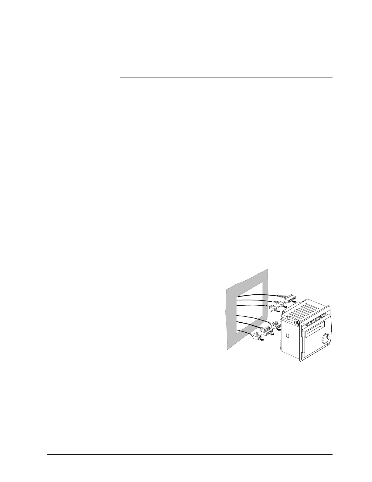
2.1.3 Mounting procedure
Description Diagram
• Turn off power supply
• Pull the prefabricated cables
through the cut-out
• Plug the connectors into the
respective sockets at the rear of the
controller
Note:
The connectors are coded to make
certain they cannot be mixed up.
2379Z11
1. step
Page 14
14/166
Siemens Building Technologies Basic Documentation RVA47.320 CE1P2379E
HVAC Products Handling 15.07.2002
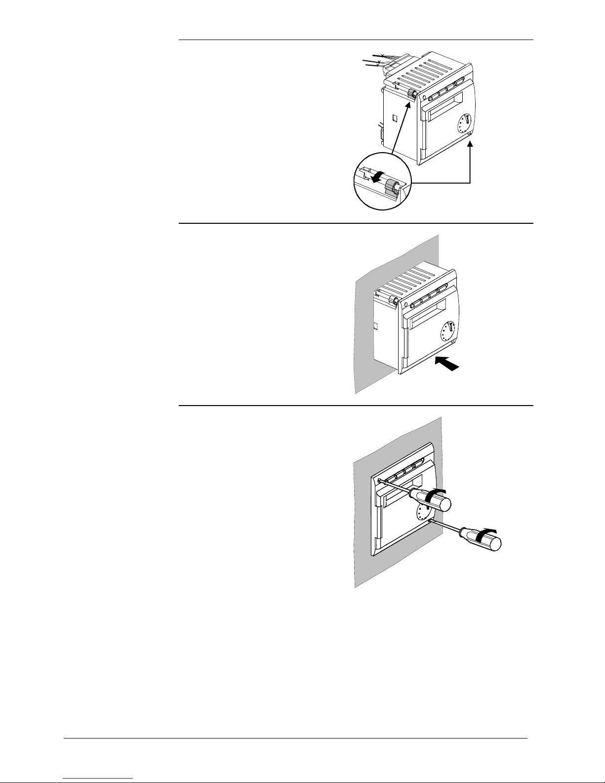
• Check to ensure the fixing levers
are turned inward
• Check to make certain there is
sufficient space between the front
panel and the fixing levers
2379Z12
• Slide the unit into the panel cut-out
without applying any force
Note:
Do not use any tools when inserting
the unit into the cut-out. If it does not
fit, check the size of the cut-out and
the housing.
2379Z13
• Secure the fixing levers by
tightening the two screws on the
front of the controller.
Note:
Tighten the screws only slightly .
When tightening the screws, the
fixing levers automatically assume
their correct positions.
2379Z142379Z14
2. step
3. step
4. step
Page 15
15/166
Siemens Building Technologies Basic Documentation RVA47.320 CE1P2379E
HVAC Products Handling 15.07.2002
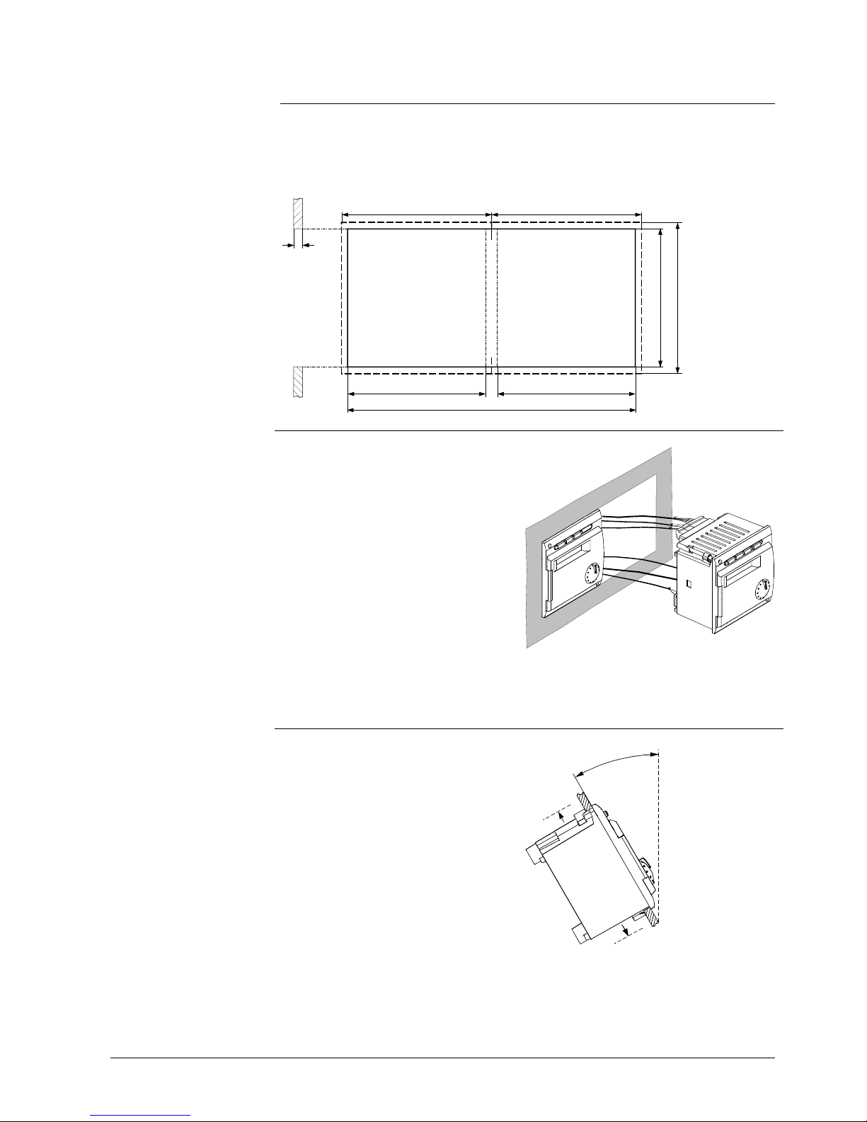
2.1.4 Required cut-out
The controller’s mounting dimensions are 91 x 91 mm.
Due to the dimensions of the front, however, the standard spacing is 96 mm.
The mechanical mounting facility allows the controller to be fitted in front panels having
a thickness of 2 to 10 mm.
The mechanical mounting facility makes
it possible to arrange several controllers
in a row in one cut-out. In that case, it is
merely necessary to have a wider panel
cutout.
2379Z15
2.1.5 Orientation
To avoid overtemperatures inside the
controller, the inclination may be no
more than 30° and there must be a
clearance of at least 10 mm on all sides
of the unit.
This allows the controller to emit the
heat generated during operation.
1
0
m
m
m
a
x
.
3
0
°
2
3
7
1
Z
1
6
1
0
m
m
Dimensions of cut-out
96
2...10
92
+0.8
-0
92
+0.8
-0
96
92
+0.8
-0
2371M02
188
96
Use of several
controllers
Page 16
16/166
Siemens Building Technologies Basic Documentation RVA47.320 CE1P2379E
HVAC Products Handling 15.07.2002
2.2 Electrical installation
2.2.1 Regulations for installation
• The connections for mains and low voltage are separated
• The wiring must be made in compliance with the requirements of safety class II.
This means that sensor and mains cables may not be run in the same duct
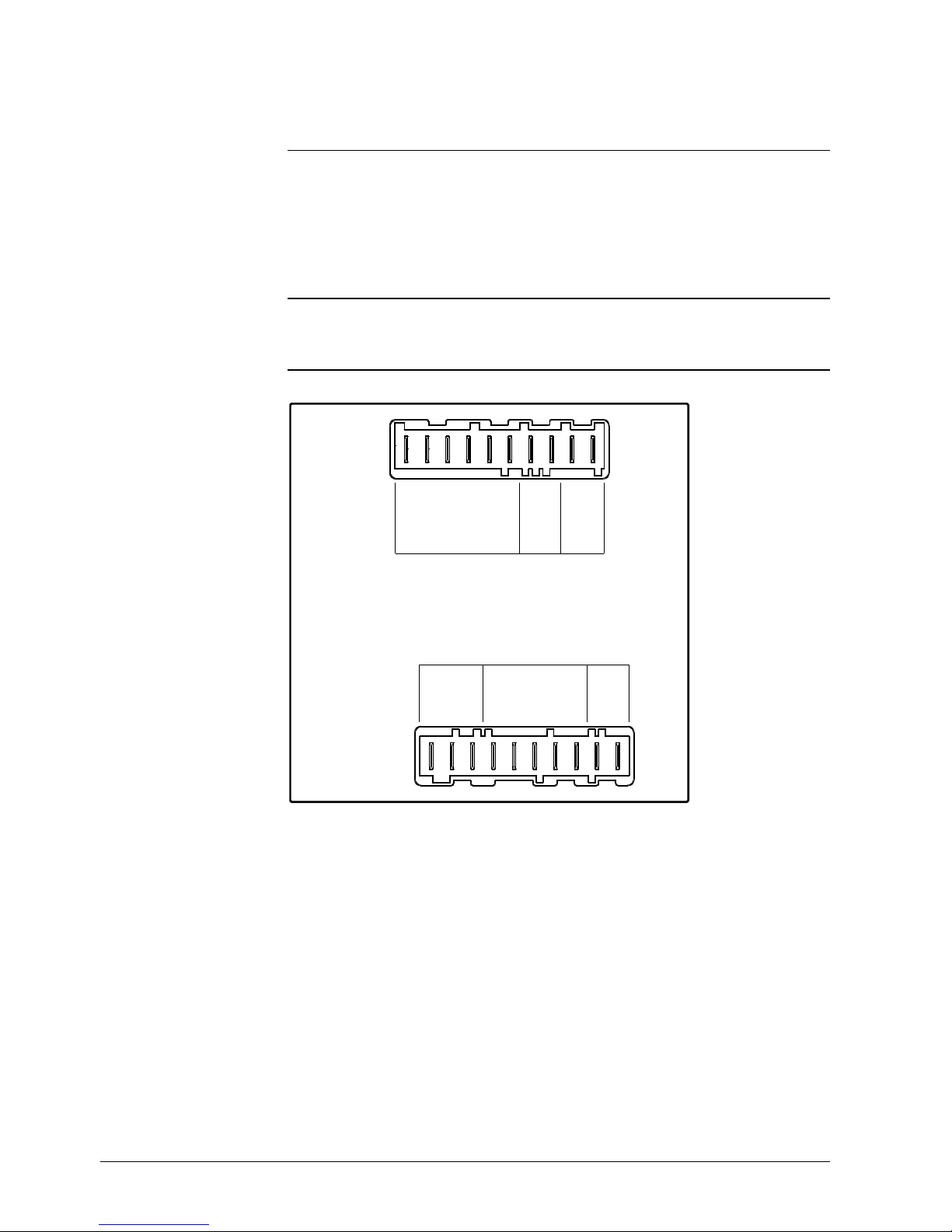
2.2.2 Wiring
When using prefabricated cables with connectors, the electrical installation is very
straightforward, owing to the coding.
Q3
Q1
F1
L
N
M
B10
B9
MDA6MB
DB
654M21M M
32F 432F LN
2379A01
B3
B70/B4
H1
Rear of controller
Connection terminals
Page 17

17/166
Siemens Building Technologies Basic Documentation RVA47.320 CE1P2379E
HVAC Products Handling 15.07.2002
Terminal Terminals Connector
H1 input H1 AGP2S.06A (white)
B70/B4 Cascade return temperature sensor B70 or
buffer storage tank temperature sensor B4
B3 D.h.w. temperature sensor or thermostat
M Ground sensors
B10 Cascade flow temperature sensor
(common flow temperature sensor)
B9 Outside sensor
MD Ground PPS (room unit, BMU) AGP2S.02G (blue)
A6 PPS (room unit, BMU)
MB Ground bus (LPB) AGP2S.02M (violet)
DB Data bus (LPB)
Terminal Terminals Connector
Q3 D.h.w. charging pump AGP3S.03B (brown)
Q1 Heating circuit or system pump:
F1 Phase Q1 / Q3
- Not used -
- Not used
- Not used
- Not used
- Not used
L Live AC 230 V (mains connection) AGP3S.02D (black)
N Neutral conductor (mains connection)
Low voltage side
Mains voltage side
Page 18
18/166
Siemens Building Technologies Basic Documentation RVA47.320 CE1P2379E
HVAC Products Handling 15.07.2002
2.3 Commissioning
To commission the controller:
1. Make certain that mounting and electrical installation are in compliance with the
relevant requirements.
2. Make all plant-specific settings as described in section "Parameter settings".
3. Reset the attenuated outside temperature (operating line 19).
4. Make the functional checks.
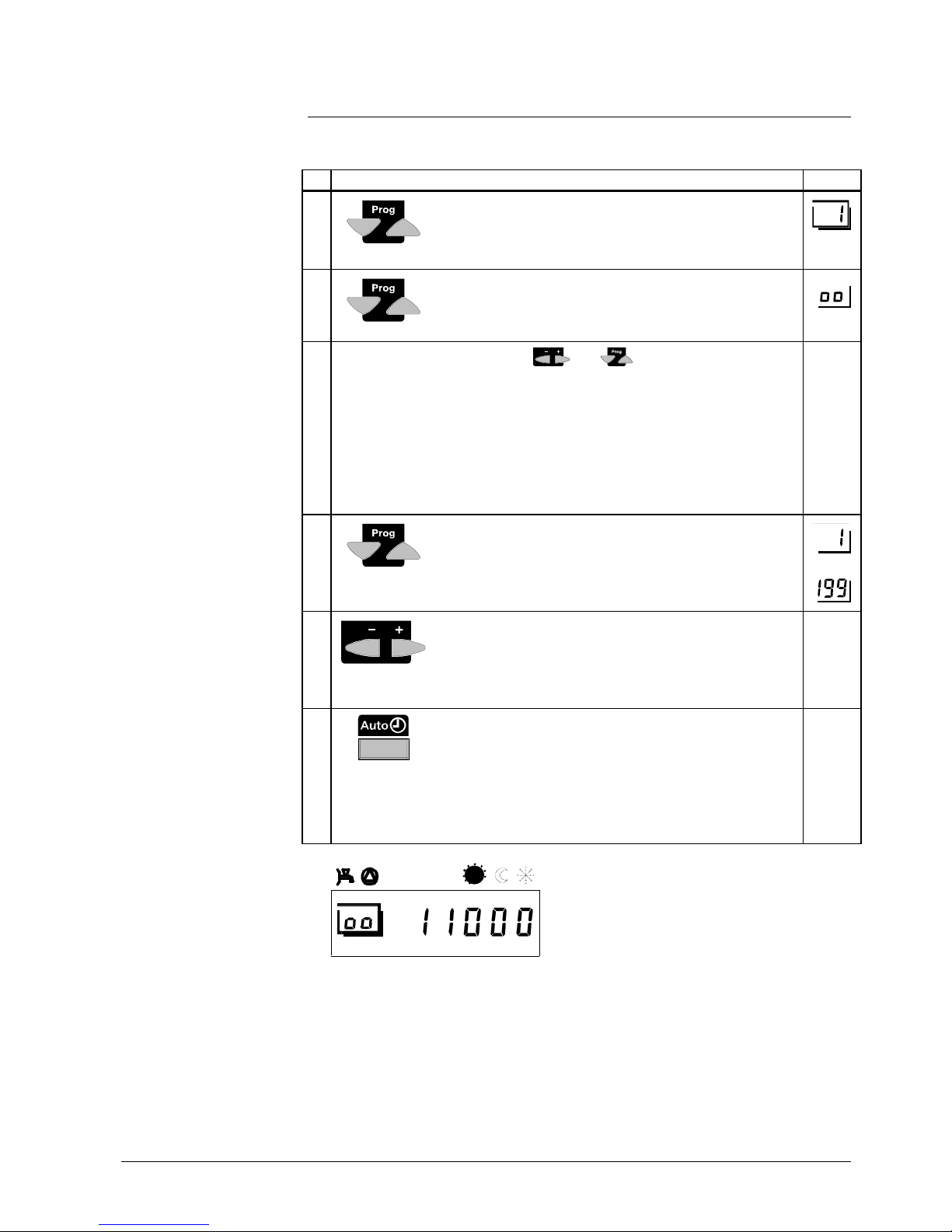
2.3.1 Functional checks
To facilitate commissioning and fault tracing, the controller allows output and input tests
to be made. With these tests, the controller’s inputs and outputs can be checked.
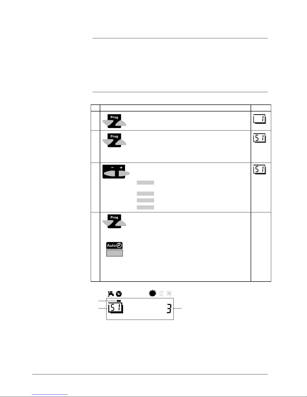
Buttons Explanation Line
1
Press one of the line selection buttons.
This will take you to the programming level "Enduser”.
2
Press both line selection buttons for at least 3 seconds.
This will take you to the programming level “Heating
engineer” and, at the same time, to the relay test (output
test).
3
Press the + or - button repeatedly, which will take you
one test step further:
Test step 0 All outputs are switched according to actual control
operation
Test step 1 All outputs are deactivated
Test step 2 D.h.w. charging pump (Q3) is activated
Test step 3 Heating circuit or system pump activated (Q1).
4
You leave the programming line "Output test” by
pressing either one of the line selection buttons,
or one of the operating mode buttons
Note:
If no button is pressed for about 8 minutes, the
controller will automatically return to the operating mode
selected last.
contin.
display
a) The pointer below the symbol indicates the output activated
b) The number indicates the current test step
c) The framed number indicates the selected setting line
Prerequisites
Output test
(relays)
Display
a)
b)
c)
2379Z02
04
812162024
Page 19
19/166
Siemens Building Technologies Basic Documentation RVA47.320 CE1P2379E
HVAC Products Handling 15.07.2002
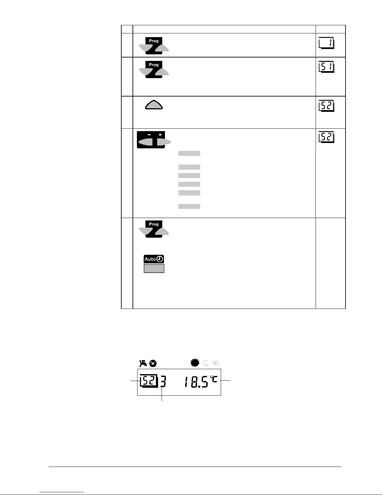
Buttons Explanation Line
1
Press one of the line selection buttons.
This will take you to the programming level "Enduser”.
2
Press both line selection buttons for at least 3
seconds.
This will take you to the programming level "Heating
engineer”.
3
Press line selection button "Up" until you reach line
52.
This will take you to the input test.
4
Press the + or - button repeatedly, which will take you
one test step further:
Test step 0 Display of the function selected on line 97 (B70/B4)
[°C].
Test step 1 Display of d.h.w. temperature (B3).
Test step 2 Display of the cascade flow temperature (B10).
Test step 3 Display of the actual outside temperature (B9)
Test step 4 Display of room temperature acquired with room
unit connected to A6
Test step 5 Display of input H1 according to the function
selected on operating line 170 [°C, - - - , o o o].
5
You leave the programming line "Input test" by
pressing either one of the line selection buttons,
or one of the operating mode or function buttons
Note:
If no button is pressed for about 8 minutes, the
controller will automatically return to the operating
mode selected last.
Contin.
display
The selected sensor values are updated within a maximum of 5 seconds. If no sensor
is present, the connecting line interrupted, or the contact open, the display shows "---”;
in the event of a short-circuit, or if the contact is closed, the LCD displays "ooo”.
a) The framed number indicates the selected setting line
b) Displayed value of the temperature measured
c) The number indicates the selected test step
Input test
(sensors)
Display
a)
c)
b)
2379Z02
04
812162024
Page 20
20/166
Siemens Building Technologies Basic Documentation RVA47.320 CE1P2379E
HVAC Products Handling 15.07.2002
2.4 Parameter settings for the enduser
The following settings can be made to meet the individual needs of the enduser.
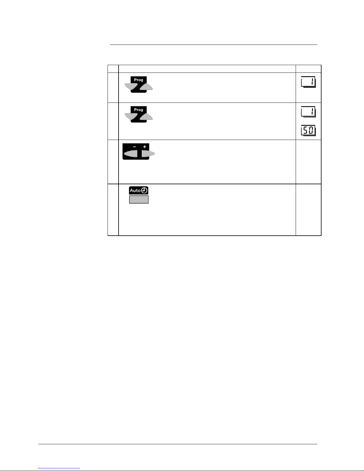
Buttons Explanation Line
1
Press one of the line selection buttons.
This will take you directly to the programming level
"Enduser”.
2
Press the line selection buttons to select the required
line.
The parameter list on the next pages contains all
available lines.
• • •
3
Press the + or - button to set the required value.
The setting will be stored as soon as you leave the
programming mode or change to another line.
The parameter list on the next 2 pages contains all
settings that can be made.
4
By pressing any of the operating mode buttons, you
leave the programming level "Enduser”.
Note:
If no button is pressed for about 8 minutes, the
controller will automatically return to the operating
mode selected last.
Contin.
display
Description
Setting
Page 21

21/166
Siemens Building Technologies Basic Documentation RVA47.320 CE1P2379E
HVAC Products Handling 15.07.2002
2.4.1 Overview of enduser parameters
Line Function Range Unit Resolution Factory
setting
Setting the clock
1 Time of day 0...23:59 h / min 1 min 2 weekday 1...7 Weekday 1 day 3 Date (day, month) 01.01...31.12 dd.MM 1 4 Year 1999...2099 jjjj 1 -
Time switch program for heating circuit
5 Weekday-preselection heating circuit
1-7 7-day block
1...7 Individual days
1-7 / 1...7 Weekday 1 day -
6 Switch-on time 1. 3rd period heating circuit 00:00...23:59 h / min 10 min 06:00
7 Switch-off time 1. 3rd period heating circuit 00:00...23:59 h / min 10 min 22:00
8 Switch-on time 2. 3rd period heating circuit 00:00...23:59 h / min 10 min - -:- 9 Switch-off time 2. 3rd period heating circuit 00:00...23:59 h / min 10 min - -:- 10 Switch-on time 3. 3rd period heating circuit 00:00...23:59 h / min 10 min - -:- 11 Switch-off time 3. 3rd period heating circuit 00:00...23:59 h / min 10 min - -:- -
D.h.w. values
13 Nominal setpoint of the d.h.w. temperature (TBWw)
TBWR Line 120
TBWmax Line 40 (OEM)
TBWR...TBWmax °C 1 55
Heating circuit values
14 Reduced room temperature setpoint (TRRw)
TRF Line 15
TRN Setpoint knob
TRF...TRN °C 0,5 16
15 Frost protection setpoint of the room temperature
(TRFw)
TRR Line 14
4...TRR °C 0,5 10
16 summer / winter changeover temperature 8...30 °C 0,5 17
17 heating curve slope
-:- - Inactive
2,5...40 Active
-:- - / 2,5...40 - 0,5 15
Actual values
18 Actual value of the room temperature (TRx) 0...50 °C 0,5 19
Actual value of the outside temperature (TAx)
To set the attenuated outside temperature to Tax, press the + / buttons simultaneously for 3 seconds.
-50...+50 °C 0,5 -
Maintenance
23 Standard time program for heating circuit and d.h.w.
To activate, press the + and - buttons simultaneously for 3 seconds
0/1 - 1 0
Time switch program for d.h.w. heating
29 preselection of weekday
1-7 7-day block
1...7 Individual days
1-7 / 1...7 Weekday 1 day -
30 Switch-on time 1. 3rd period d.h.w. 00:00...23:59 h / min 10 min 06:00
31 Switch-off time 1. 3rd period d.h.w. 00:00...23:59 h / min 10 min 22:00
32 Switch-on time 2. 3rd period d.h.w. 00:00...23:59 h / min 10 min - -:- 33 Switch-off time 2. 3rd period d.h.w. 00:00...23:59 h / min 10 min - -:- 34 Switch-on time 3. 3rd period d.h.w. 00:00...23:59 h / min 10 min - -:- 35 Switch-off time 3. 3rd period d.h.w. 00:00...23:59 h / min 10 min - -:- -
Service
49 Indication of BMU error code
1...4 = BMU number, 1...255 = error code
1...4 / 0...255 - 1 -
50 indication of faults 0..255 / 00.01–14.16 - 1 -
Page 22
22/166
Siemens Building Technologies Basic Documentation RVA47.320 CE1P2379E
HVAC Products Handling 15.07.2002
2.5 Parameter settings for the heating engineer
Configuration and parameter settings to be made by the heating engineer.
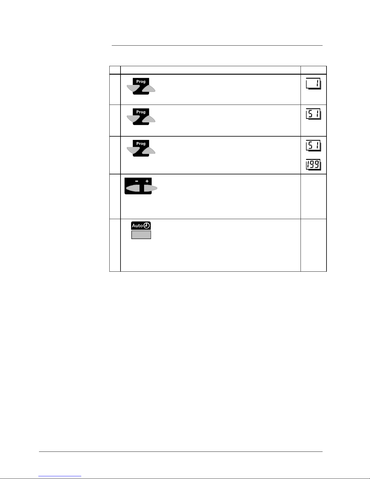
Buttons Explanation Line
1
Press one of the line selection buttons.
This will take you first to the programming level
"Enduser”.
2
Press both line selection buttons for at least 3 seconds.
This will take you to the programming level "Heating
engineer”.
3
Press the line selection buttons to select the required
line.
The parameter list on the next 2 pages contains all
available lines.
• • •
4
Press the + or - button to set the required value.
The setting will be stored as soon as you leave the
programming mode or change to another line.
The parameter list on the next 2 pages contains all
settings that can be made.
5
You leave the programming level "Heating engineer" by
pressing one of the operating mode buttons.
Note:
If no button is pressed for about 8 minutes, the
controller will automatically return to the operating
mode selected last.
Contin.
display
Description
Setting
Page 23

23/166
Siemens Building Technologies Basic Documentation RVA47.320 CE1P2379E
HVAC Products Handling 15.07.2002
2.5.1 Overview of heating engineer parameters
Line Function Range Unit Resolution Factory
setting
Service values
51 Output test (relay test)
0 Control mode according to the operational status
1 All outputs are deactivated
2 D.h.w. charging pump ON Q3
3 Heating circuit / system pump ON Q1
0...3 - 1 0
52 Input test (sensor test)
0 Cascade return temperature sensor B70/B4
or buffer storage tank temperature sensor
1 D.h.w. temperature sensor B3
2 Cascade flow temperature sensor B10
3 outside temperature sensor B9
4 Room temperature sensor (room unit) A6
5 input H1 H1
0...5 - 1 0
53 Display of plant type 27...36 / 65...67 - 1 54 displaying the PPS communication
- - - No communication
1...12 PPS device address
0...255 identification code
--- / 1..12 / 0..255 - 1 -
Actual values
55 Actual value of boiler temperature of BMUs (TKx) 1)
1...4 = BMU number, 0...140 = actual value of boiler temperature
(interrogate with + / - buttons)
1...4 / 0...140 °C 1 -
56 Actual value of cascade flow temperature
Input B10
0...140 °C 1 -
57 Actual value of cascade return temperature
Input B70
0...140 °C 1 -
58 actual value of buffer storage tank temperature
Input B4
0...140 °C 1 -
59 Actual value of the d.h.w. temperature (TBWx)
1)
(Input B3 or value from BMU)
0...140 °C 1 -
60
Attenuated outside temperature
(Taxged)
-50.0...+50.0 °C 0.5 -
61
Composite outside temperature
(TAxgem)
-50.0...+50.0 °C 0.5 -
62 outside temperature source
--.-- No signal
00.01 Segment / device address
--.-- / 00.01...14.16 - - -
Setpoints
65 Setpoint of the boiler temperature of BMUs (TKx) 1)
1...4 = BMU number, 0...140 = actual value of boiler temperature
(interrogate with + / - buttons)
1...4 / 0...140 °C 1 -
66 Setpoint of the cascade flow temperature 0...140 °C 1 69 Setpoint of d.h.w. temperature (TBWw) 0...140 °C 1 70 Nominal room temperature setpoint
Nominal setpoint plus readjustment made on the room unit
0.0...35.0 °C 0,5 -
71 Setpoint of room temperature (TRRw) 0.0...35.0 °C 0,5 72 Flow temperature setpoint (TVw) 0...140 °C 1 -
Heat generation values
75
Display of the available cascade boilers
(--- = none)
--- / 00.1...16.3 - 01.1 -
76 display lead boiler --- / 00.1...16.3 - 01.1 77
Remaining number of operating hours for changeover
of boiler
sequence
Only if a value is selected on line 130, otherwise the LCD displays - -
-
0...990 h 1 -
Page 24

24/166
Siemens Building Technologies Basic Documentation RVA47.320 CE1P2379E
HVAC Products Handling 15.07.2002
Line Function Range Unit Resolution Factory
setting
80 Burner hours run BMU 1
1)
0...65535 h 1 0
81 Burner hours run BMU 2
1)
0...65535 h 1 0
82 Burner hours run BMU 3
1)
0...65535 h 1 0
83 Burner hours run BMU 4
1)
0...65535 h 1 0
90 Minimum limitation of the boiler temperature (TKmin) 1) TKmin
OEM
...TKmax
(max 95°C)
°C 1 8
91 Nominal output BMU 1
1)
0...255 kW 1 20
92 Nominal output BMU 2
1)
0...255 kW 1 20
93 Nominal output BMU 3
1)
0...255 kW 1 20
94 Nominal output BMU 4
1)
0...255 kW 1 20
Configuration of plant
95
pump function output Q1
1 Heating circuit pump or no pump
2 System pump for heating circuits only
3 System pump for heating circuits and d.h.w. storage tank
4 d.h.w. circulating pump
5 Pump H1
1...5 - 1
97
use sensor input B70/B4
1 Cascade return temperature (B70)
2 Buffer storage tank temperature sensor (B4)
1...2 - 1 1
Space heating
100 parallel displacement of the heating curve -4.5...+4.5 K (°C) 0,5 0,0
101 room influence
0 Inactive
1 Active
0 / 1 - 1 1
102 Switching differential of the room temperature (SDR)
- - . - Inactive
0,5...4,0 Active
- - . - / 0.5...4.0 K (°C) 0,5 - - . -
103 Minimum limitation of the flow temperature setpoint
(TVmin)
TVmax Line 104
8...Tvmax °C 1 8
104 Maximum limitation of the flow temperature setpoint
(TVmax)
Tvmin Line 103
TVmin...95 °C 1 80
105 type of building construction
0 Heavy
1 Light
0 / 1 - 1 1
106 adaption of the heating curve
0 Inactive
1 Active
0 / 1 - 1 1
107 Maximum forward shift of optimum start control
0 No forward shift
00:00...06:00 hh:mm 10 min 00:00
108 Maximum forward shift of optimum stop control
0 No forward shift
00:00...06:00 hh:mm 10 min 00:00
D.h.w.
120 Reduced setpoint of d.h.w. temperature (TBWR)
TBWw Line 13
8...TBWw °C 1 40
121 release of d.h.w. heating
0 24 h/day
1 According to the heating circuit time switch program)s) with
forward shift
2 According to d.h.w. time switch program (lines 29...35)
0...2 - 1 1
122 switching program circulating pump
0 According to heating circuit time switch program
1 According to release of d.h.w. heating
0...1 - 1 1
123 Assignment of d.h.w. heating
0 For local consumer only
1 For all consumers in the same segment
2 For all consumers in the system
0...2 - 1 2
Page 25

25/166
Siemens Building Technologies Basic Documentation RVA47.320 CE1P2379E
HVAC Products Handling 15.07.2002
Line Function Range Unit Resolution Factory
setting
124 D.h.w. charging
0 Once per day (forward shift 2.5 h)
1 Several times per day (forward shift 1h)
0 / 1 - 1 1
125 Type of d.h.w. demand
0 Sensor
1 Control thermostat
0 / 1 - 1 0
126 Flow temperature boost for d.h.w. 0...30 K 1 16
127 d.h.w. priority
0 MK + PK absolute
1 MK + PK shifting
2 None (parallel)
3 MK shifting, PK absolute
0...3 1 1 1
129 demand for heat with reduced d.h.w. setpoint
0 No (application with buffer storage tank)
1 Yes
0 / 1 - 1 1
Boiler cascade
130 changeover of boiler sequence in cascades
--- No automatic changeover (fixed boiler sequence)
10...990 Changeover according to the selected number of hours
--- / 10...990 - / hours 10 500
131 Exclusion with autom. changeover of boiler
sequence
0 None
1 First boiler
2 Last boiler
3 First and last boiler
0...3 - 1 0
132 Lead boiler with the fixed sequence 00.1...16.3 - 01.1 133 Switch-on delay lag boilers 2...120 min 1 5
134 Restart lock of BMUs 0...1800 s 10 300
LPB / system
140 LPB device address
0 Standalone
1...16 Device number
0...16 - 1 1
141 LPB segment address
0 Central segment (heat generation)
1...14 Segment (heat consumers)
0...14 - 1 0
142 LPB power supply
0 Off (central bus power supply)
1 AUTOMATIC (controller - bus power supply)
0 / 1 - 1 1
143 Displaying the LPB power supply ON / OFF - - 144 displaying the LPB communication ON / OFF - - 145
Range of action of central changeover
0 In the segment
1 In the system (if segment address = 0)
0 / 1 - 1 1
146 Automatic summer / winter changeover
0 Effect on local heating circuit only
1 Central changeover of all heating circuits
0 / 1 - 1 0
147 Central standby switch
0 OFF (Inactive)
1 ON (all units on standby)
0 / 1 - 1 0
148 clock mode
0 Autonomous clock
1 System time without remote adjustment
2 system time with remote adjustment
3 System clock (master)
0...3 - 1 3
149 Winter- / summertime changeover 01.01...31.12 tt.MM 1 25.03
150 Summer- / wintertime changeover 01.01...31.12 tt.MM 1 25.10
input H1
170 input H1
0 Changeover of operating mode (HC standby / d.h.w. off)
1 Changeover of operating mode (HC standby)
2 Minimum setpoint of flow temperature (setting on line 171)
3 Heat generation lock
4 Heat demand DC 0...10 V
0...4 - 1 0
Page 26

26/166
Siemens Building Technologies Basic Documentation RVA47.320 CE1P2379E
HVAC Products Handling 15.07.2002
Line Function Range Unit Resolution Factory
setting
171 minimum setpoint of flow temperature contact H1
If activated at input H1 (setting 2)
8...TKmax °C 1 70
172 Maximum value of heat demand
If activated at input H1 (setting 4)
5...130 °C 1 100
173 operating action of the contact H1
0 N.C. contact
1 N.O.
0 / 1 - 1 1
1)
If a BMU is connected via LPB, this setting will not be active.
The respective setting must be made directly on the BMU.
Page 27
27/166
Siemens Building Technologies Basic Documentation RVA47.320 CE1P2379E
HVAC Products Handling 15.07.2002
2.6 Parameter settings for the OEM
Boiler-specific settings and protective functions for the boiler manufacturer.
Buttons Explanation Line
1
Press one of the line selection buttons.
This will take you first to the programming level
"Enduser”.
2
9 s
Press both line selection buttons for at least 9 seconds.
A special display for entering the code will appear.
3
CODE
Press buttons
and to enter the required
combination of the access code.
If the combination of buttons is correct, you reach the
programming mode ”OEM”.
Wrong code:
If the code has been entered incorrectly, the display will
change to the "Parameter settings for the heating
engineer”.
4
Press the line selection buttons to select the required
line.
The parameter list on the next 2 pages contains all
available lines.
• • •
5
Press the + or - button to set the required value.
The setting will be stored as soon as you leave the
programming mode or change to another line.
The following parameter list contains all available lines.
6
You leave the programming level "OEM" by pressing any
of the operating mode buttons.
Note:
If no button is pressed for about 8 minutes, the controller
will automatically return to the operating mode selected
last.
Contin.
display
2379Z02
04
812162024
Whether correct or incorrect, each push of a button represents irrevocably a digit of the
code.
As a confirmation, the respective digit changes to 1.
Description
Setting
Example
Page 28

28/166
Siemens Building Technologies Basic Documentation RVA47.320 CE1P2379E
HVAC Products Handling 15.07.2002
2.6.1 Overview of OEM parameters
Line Function Range Unit Resolution Factory
setting
Heat source OEM
1
Minimum limitation of the boiler temperature:OEM
1)
(TKminOEM)
8...95 °C 1 8
2 Maximum limitation of the boiler temperature (TKmax) 8...120 °C 1 80
8 Pump overrun time
(after burner OFF)
0...20 min 1 5
22 Minimum limitation of boiler return temperature 8...95 °C 1 8
25 Calibration of actual output value BMU 1
1)
-100...100 - 1 0
26 Calibration of actual output value BMU 2
1)
-100...100 - 1 0
27 Calibration of actual output value BMU 3
1)
-100...100 - 1 0
28 Calibration of actual output value BMU 4
1)
-100...100 - 1 0
Space heating OEM
30 Gain factor of room influence (KORR) 0...20 - 1 4
31 Constant for quick setback (KON)
(without room sensor)
0...20 - 1 2
32 Boost of room temperature setpoint
(with boost heating)
0...20 K (°C) 1 5
33
Frost protection for the plant
0 Inactive
1 Active
0 / 1 - 1 1
34 overtemperature protection for the pump heating circuit
0 Inactive
1 Active
0 / 1 - 1 1
35 Heat gains (Tf) -2...+4 °C 0,1 0
36 adaption sensitivity 1 1...15 - 1 15
37 adaption sensitivity 2 1...15 - 1 15
D.h.w. OEM
40 Maximum nominal setpoint of the d.h.w. temperature
(TBWmax)
8...80 °C 1 60
41 Switching differential of the d.h.w. temperature 0...20 K (°C) 1 5
42 Legionella function
0 = OFF
1 = ON
0 / 1 - 1 1
43 setpoint of the legionella function 8...95 °C 1 65
44
Protection against discharging during d.h.w. heating
0 = no protection against discharging
1 = always protection against discharging
2 = protection against discharging only when heat generation is
locked
0...2 - 1 2
Cascade settings OEM
50 cascade management strategy
1 autonomous 1
2 autonomous 2
3 autonomous 3
4 linked 1
5 linked 2
6 linked 3
1...6 - 1 2
51 Lower limit of output range (Pmin) 0...Pmax % 1 40
52 Upper limit of output range (Pmax) Pmin...100 % 1 90
56 Mandatory time on basic stage when boilers are added 10...1200 s 10 60
60 Minimum temperature differential at the pressureless
header
0...20 K (°C) 1 4
Page 29

29/166
Siemens Building Technologies Basic Documentation RVA47.320 CE1P2379E
HVAC Products Handling 15.07.2002
Line Function Range Unit Resolution Factory
setting
Configuration of plant
90 continuous display
0 Weekday / time of day
1 Actual value of cascade flow temperature
0 / 1 - 1 0
Service values OEM
91 software version 00.0...99.9 - 1 92 device operating hours 0...500000 h 1 -
1)
If a BMU is connected via LPB, this setting will not be active.
The respective setting is to be made directly on the BMU.
Page 30
30/166
Siemens Building Technologies Basic Documentation RVA47.320 CE1P2379E
HVAC Products Handling 15.07.2002
2.7 Operation
Operating instructions are inserted at the rear of the unit's front cover.
2379Z01
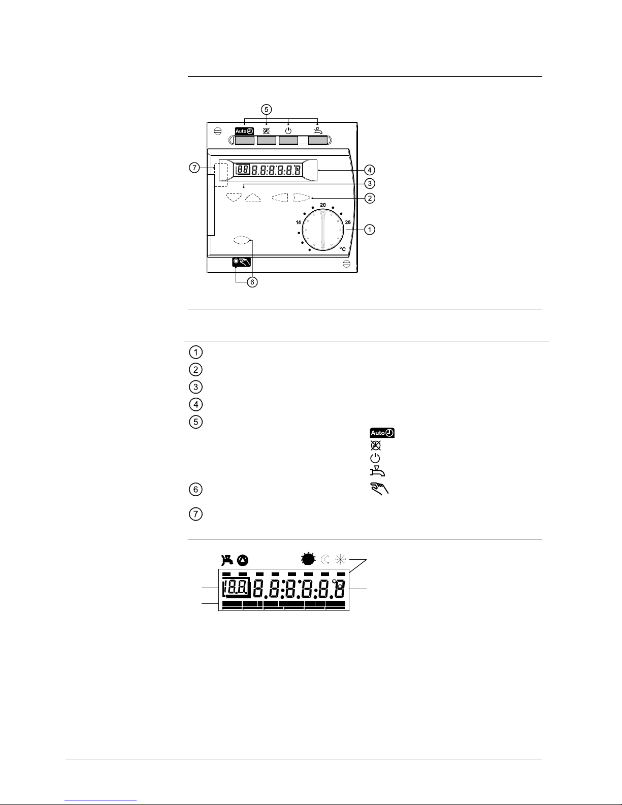
2.7.1 Operating elements
O
p
erating element
F
unction
Room temperature setpoint knob
Adjustment of room temperature setpoint
Setting buttons
Parameter settings
Line selection buttons
Selection of parameters / switching of lines
Display
Readout of actual values and settings
Operating mode buttons
Operating mode changes to:
Automatic operation
continuous operation
Standby
D.h.w. heating ON / OFF
Function button with LED for
manual operation
Manual operation ON / OFF
Connection facility for PC tool
Diagnostics and service
a) Symbols for indicating the operational status with the black bars (level pointers)
When the ECO function is active, the current level pointer flashes.
b) Display during normal control mode or when making settings
c) Programming line when making settings.
d) Time bar for normal control mode or when making settings.
Introduction
Display
a)
b)
c)
2379Z02B
d)
04
812162024
Page 31

31/166
Siemens Building Technologies Basic Documentation RVA47.320 CE1P2379E
HVAC Products Handling 15.07.2002
2.8 Operational faults
2.8.1 No display on the controller:
• Is the heating plant's main switch turned on?
• Are the fuses in order?
• Check the wiring
2.8.2 Controller displays the wrong time of day:
• Set the correct time of day on the controller (operating line 1).
• Set the correct time of day on the clock master (if present).
2.8.3 One of the BMUs does not switch on
• Does the BMU really have to operate? (Check cascade lead strategy, delayed
switching on?)
• Press BMU's lockout reset button.
• Check the electromechanical control thermostat (TR) and the manual reset safety
limit thermostat (STB)
• Check wiring and fuse of the BMU.
• Check communication link to the BMU (operating line 54)
• Check wiring of the cascade temperature sensors (sensor test, operating line 52).
2.8.4 One of the pumps does not run
• Is the right type of plant displayed (operating line 53)?
• Is the pump correctly defined? (Operating line 95)
• Check wiring and fuse of the pump (relay test, operating line 51)
• Check wiring of the sensors (sensor test, operating line 52)
2.8.5 D.h.w. is not being heated:
• Has the button for d.h.w. heating been pressed?
• Check setpoint of the d.h.w. temperature
• Check if d.h.w. heating is released
• Check wiring and fuse of the charging pump (relay test, operating line 51)
• Check wiring of the d.h.w. temperature sensor (sensor test, operating line 52)
• Check setting of the electromechanical control thermostat (TR) installed on the
boiler. It must be above the TKmax setting
2.8.6 The room temperature does not agree with the
required temperature level:
• Does the room temperature setpoint agree with the required temperature level?
(Knob on the controller or on the room unit)
• Is the required operating mode indicated?
• Are weekday, time of day and the displayed heating program correct?
(Operating lines 1...11)
• Has the heating curve slope been correctly set? (Operating line 17)
• Check wiring of outside sensor (operating line 52)
• Has the ”Setting knob for the nominal room temperature setpoint” with the ”Parallel
displacement of the heating curve” (operating line 100) been calibrated based on
the effective room temperature?
2.8.7 Error message; display shows "ER"
• Select operating line 50 which gives you the error code and error address. There,
you see the error code and the address of the error. Refer to section "Indication of
errors" for a list of the possible error codes and their descriptions.
Page 32

32/166
Siemens Building Technologies Basic Documentation RVA47.320 CE1P2379E
HVAC Products Description of the enduser settings 15.07.2002
3 Description of the enduser settings
User interface
3.1 Heating circuit operating modes
• Straightforward selection of heating circuit operating modes
The control provides 3 different heating circuit operating modes that can be directly
selected as required.
Select the required operating mode by pressing the respective operating mode button.
It is located on the controller front for direct access by the user.
Operating
mode
Designation Effect of selected operating mode
Automatic
operation
• Heating according to the time program
(operating lines 5 to 11)
• Temperature setpoints according to the heating
program
• Protective functions active
• Changeover on the room unit active
• Automatic summer / winter changeover and
automatic 24-hour heating limit active (ECO
functions)
continuous
operation
• Heating mode with no time program
• Temperature adjustment with the setpoint knob
• Protective functions active
• Changeover on room unit inactive
• Automatic summer / winter changeover and
automatic 24-hour heating limit inactive (ECO
functions)
Standby
• Heating OFF
• Temperature according to frost protection
• Protective functions active
• Changeover on room unit inactive
Benefit
Description
Setting
Page 33

33/166
Siemens Building Technologies Basic Documentation RVA47.320 CE1P2379E
HVAC Products Description of the enduser settings 15.07.2002
The selected operating mode is indicated by illuminated buttons. A number of functions
can cause the displayed selection to change. The following table shows the possible
statuses. The following table shows the possible statuses:
Function Effect on button and meaning
Heat generation lock
Line 170 = 3
• Selected HC operating mode button flashes when
contact H1 is closed
• D.h.w. operating mode button flashes when
switched on
Changeover of operating
mode
Line 170 = 0
• Selected HC operating mode button
flashes
when contact H1 is closed
• D.h.w. operating mode button flashes when
switched on
Changeover of operating
mode
Line 170 = 1
• HC operating mode
flashes
• D.h.w. operating mode button will not be affected
Minimum setpoint of flow
temperature
Line 170 = 2
• Selected HC operating mode button flashes when
contact H1 is closed.
• D.h.w. operating mode button will not be affected
Central standby switch
Line 147 = 1
• HC operating mode
flashes
• D.h.w. operating mode button will not be affected
Function Effect on button and meaning
Occupancy button
• HC operating mode
flashes when occupancy
button is active.
• D.h.w. operating mode button will not be affected
Holiday function
• HC operating mode
flashes when holiday
function is active
• D.h.w. operating mode button flashes when
switched on
Changeover of the operating mode on the room unit is active only if the controller is in
automatic mode
.
The room temperature is transmitted to the controller via PPS, independent of the
selected operating mode.
3.2 Operating mode of d.h.w. heating
• Selection of d.h.w. heating mode independent of heating operation
• Selection is made directly on the user interface
D.h.w. heating can be switched on and off independent of the other operating modes.
D.h.w. heating is selected by pressing the respective button on the controller's user
interface.
Illuminated buttons
Settings on the controller
Settings on the room unit
Effect of room unit
Benefit
Description
Setting
Page 34

34/166
Siemens Building Technologies Basic Documentation RVA47.320 CE1P2379E
HVAC Products Description of the enduser settings 15.07.2002
By pressing the respective button, d.h.w. heating is switched on or off.
• D.h.w. heating OFF - button dark.
D.h.w. is not being heated. Frost protection remains active, however, and prevents
the storage tank temperature from falling below a certain level
• D.h.w. heating ON - button illuminated.
The d.h.w. is heated according to the settings made
The following settings affect d.h.w. heating:
• Time switch program d.h.w. heating (lines 29...35)
• Nominal d.h.w. temperature setpoint (line 13)
• Reduced d.h.w. temperature setpoint (line 120)
• Release of d.h.w. heating at the nominal setpoint (line 121)
• Assignment of d.h.w. heating (line 123)
• D.h.w. heating (line 124)
• Type of d.h.w. demand (line 125)
The d.h.w. values that can be adjusted on the controller apply to both d.h.w. heating by
the controller and d.h.w. heating by a BMU supplied by Landis & Staefa. Some BMUs
of other manufacture also support this function.
3.3 Nominal room temperature setpoint
• Straightforward setting of the required nominal room temperature setpoint
The heating system uses 3 different setpoints that can be adjusted:
• The nominal room temperature setpoint described here
• The reduced room temperature setpoint (setting on line 14)
• The frost protection setpoint of the room temperature (setting on operating line 15)
The nominal room temperature setpoint is preadjusted with the setpoint knob. It is
located on the controller front for direct access by the user.
Setting range Unit Factory setting
8...26 °C 20
0 2 4 6 8 10 12 14 16 18 20 22 24 26
°C
2379Z17
Room temperature setpoint setting ranges
14 Setting "Reduced room temperature setpoint”
15 Setting "Frost protection setpoint of the room temperature”
When the nominal room temperature setpoint is active, the rooms will be heated
according to the adjustment made with the setpoint knob.
Effect in the various operating modes:
Effect
Important settings
Note
Benefit
Description
Setting
Effect of temperature
setting
Page 35

35/166
Siemens Building Technologies Basic Documentation RVA47.320 CE1P2379E
HVAC Products Description of the enduser settings 15.07.2002
Operating
mode
Effect of knob adjustment
Adjustment
acts on the heating periods
Adjustment acts continuously
Adjustment has no effect
The adjustment made with the setpoint knob has priority over the reduced room
temperature setpoint entered (line 14). Especially in a situation when the adjustment
made with the knob is lower.
During the heating periods, the nominal room temperature setpoint is maintained. The
heating periods are in accordance with the settings made on lines 6 to 11.
0 2 4 6 8 10 12 14 16 18 20 22 24
h
Mo
...
So
2373Z11
When using a room unit without setpoint readjustment (QAA50), the setpoint knob on
the controller acts as described above.
When using a room unit featuring setpoint readjustment (QAA70), the setpoint knob on
the controller is inactive. In that case, the nominal setpoint adjusted on the room unit
applies.
A connected room unit is active only when operating mode
is selected on the
controller.
3.4 Manual operation
• Partly manual heating operation
In operating mode “Manual operation”, the plant components on the consumer side
must be manually adjusted and monitored. The control functions of the unit are only
used for controlling the BMUs.
The BMUs are released and use their boiler temperature sensor to control the
temperature at the level of the maximum limitation of the BMU setpoint (TKmax.)
Factory setting 80 °C. The actual boiler temperatures are displayed on setting line 55.
Activation:
Manual operation is activated by pressing this button. It is accessible
only when the cover of the controller is open
Deactivation:
• By pressing one of the operating mode buttons
• By pressing again the manual operation button
When deactivating the function, the controller will automatically return to the operating
mode previously selected.
As soon as manual operation is selected, all relays will switch to the following statuses:
Note
Example
Room unit
Benefit
Description
Common flow temperature
Setting
Note
Effect
Page 36

36/166
Siemens Building Technologies Basic Documentation RVA47.320 CE1P2379E
HVAC Products Description of the enduser settings 15.07.2002
Output
Terminals Status
BMU PPS All boilers released, fixed
heat demand at TKmax
Heating circuit or system
pump:
Q1 ON (uncontrolled)
D.h.w. charging pump Q3 ON (uncontrolled)
TKmax = maximum limitation of BMU setpoint (operating line 2
OEM
)
Common flow temperature (cascade flow temperature):
04
812162024
2379Z02
Display
Page 37

37/166
Siemens Building Technologies Basic Documentation RVA47.320 CE1P2379E
HVAC Products Description of the enduser settings 15.07.2002
Setting the clock
• Straightforward changeover from summer- to wintertime, and vice versa
• Fast and easy-to-understand time settings
To ensure proper operation of the heating program, the 24-hour time switch with the
time of day and weekday must be correctly set.
The time of day can be set from a remote location via the bus system, provided clock
operation is appropriately set. Also refer to clock operation on operating line 148.
3.5 Time of day
1. Press the operating line selection buttons to select line 1.
2. Press the + / - buttons to set the time of day.
Setting range Unit
00:00...23:59 Hour : Minute
The controller's clock time is set in agreement with the correct time. This setting is
important to make certain the controller’s heating program will operate correctly.
• During the setting procedure, the clock continues to run
• Each time the + or - button is pressed, the seconds are reset to zero
3.6 Weekday
1. Press the operating line selection buttons to select line 2.
2. Press the + / - buttons to select the weekday.
Setting range Unit
1...7 Weekday
The time of day will be set to the selected weekday. This setting is important to make
certain the controller’s heating program will operate correctly.
1 = Monday
2 = Tuesday
3 = Wednesday
4 = Thursday
5 = Friday
6 = Saturday
7 = Sunday
Benefit
Description
System time
Setting
Effect
Notes
Setting
Effect
Weekday table
Page 38

38/166
Siemens Building Technologies Basic Documentation RVA47.320 CE1P2379E
HVAC Products Description of the enduser settings 15.07.2002
3.7 Date (day, month)
Setting range Unit
01:01...31:12 Day month
Day and month of the controller will be based on this setting. This setting of date is
important to make certain the controller’s holiday program and summer- / wintertime
changeover will operate correctly.
3.8 Year
Setting range Unit
1999...2099 Year
The year of the controller will be based on this setting. This setting of year is important
to make certain the controller’s holiday program and summer- / wintertime changeover
will operate correctly.
Setting
Effect
Setting
Effect
Page 39

39/166
Siemens Building Technologies Basic Documentation RVA47.320 CE1P2379E
HVAC Products Description of the enduser settings 15.07.2002
Time switch program for space heating
• The heating system operates only if there is demand for heat.
• The user can set the heating periods to suit his lifestyle.
• Energy can be saved by making adequate use of the heating program.
The time switch program for space heating consists of the switching times that can be
entered for the weekdays or the 7-day block.
The time switch program for space heating and the time switch program for d.h.w.
heating operate independently of one another.
3.9 Preselecting the weekday
With this setting, you select the weekdays or the 7-day block for which the switching
times of the time switch program apply.
The heating program thus set becomes active when selecting automatic mode
.
1. Press the operating line selection buttons to select line 5.
2. Press the + / - buttons to preselect the 7-day block or the individual day.
Setting range Unit
1-7
1...7
7-day block
Individual days
• This setting must be made before the switching times are entered!
• For every day on which other switching times shall apply, the preselection of the
individual day with subsequent entry of the switching times must be repeated
This setting is used to select either the whole week (1-7) or individual days (1...7).
7-day block
Entry of the switching times from operating line 6 to 11 is identical for every day from
Monday through Sunday.
0 2 4 6 8 10 12 14 16 18 20 22 24
h
Mo
...
So
2373Z11
Switching time for nominal setpoint
Switching time for reduced setpoint
Benefit
Description
Description
Setting
Important
Effect
Entry of 1-7
Example:
Page 40

40/166
Siemens Building Technologies Basic Documentation RVA47.320 CE1P2379E
HVAC Products Description of the enduser settings 15.07.2002
Individual days
The setting of the switching times from operating line 6 through 11 is entered only for
the individual day selected here.
Tip
First, choose the 7-day block (1-7) to enter the switching times that apply to the
majority of days; then, select the individual days (1...7) to make the required
adjustments.
0 2 4 6 8 10 1 2 1 4 16 18 20 2 2 2 4 h
Sa
Mo
Di
Mi
Do
Fr
So
237 3Z12
3.10 Switching times
With this setting, you determine the switching times for space heating. At these
switching times, the temperature setpoints of the heating circuit change.
The heating program thus set becomes active when selecting automatic mode
.
1. Press the line selection buttons to select line 6 to 11.
2. Press the + / – buttons to set the switching time on each line.
Setting range Unit Factory setting
- -:- -...24:00 h : min
See "Program overview"
below
First, select the weekday (operating line 5) for which the switching times shall be
entered!
The controller then makes a check to ensure the entries have been made in the correct
order.
At the times entered, the program will switch to the respective temperature setpoints.
The table below shows at what times the setpoints will be activated.
Entry of 1...7
Example:
Description
Setting
• • •
! Important
Note
Effect
Page 41

41/166
Siemens Building Technologies Basic Documentation RVA47.320 CE1P2379E
HVAC Products Description of the enduser settings 15.07.2002
Entry:
– – : – – Switching point inactive
00:00...24:00 At the time entered, heating to the respective temperature is ensured.
Line
Switching point Temperature setpoint Standard
Switch-on time period 1 Setpoint of knob
06:00
Switch-off time period 1 Reduced setpoint
22:00
Switch-on time period 2 Setpoint of knob
– – : – –
Switch-off time period 2 Reduced setpoint
– – : – –
Switch-on time period 3 Setpoint of knob
– – : – –
Switch-off time period 3 Reduced setpoint
– – : – –
When using a QAA70 room unit, the heating program will be acted upon. However, this
works only if operating mode “AUTO” is selected on the controller.
Program overview
Effect of room unit
Page 42

42/166
Siemens Building Technologies Basic Documentation RVA47.320 CE1P2379E
HVAC Products Description of the enduser settings 15.07.2002
D.h.w. values
3.11 Nominal d.h.w. temperature setpoint
• D.h.w. heating only if there is a demand for it
• Possibility of using 2 different d.h.w. temperature setpoints
1. Press the operating line selection buttons to select line 13.
2. Press the + / – buttons to adjust the nominal setpoint of the d.h.w. temperature.
Setting range Unit Factory setting
TBWR...TBWmax °C 55
TBWR Reduced setpoint of d.h.w. temperature (setting on operating line 120)
TBWmax Maximum nominal setpoint of d.h.w. temperature (setting on line 40
OEM
)
0 10 20 30 40 50 60 70 80 90 100 120 130 140 °C
2379Z16
The temperature setpoint during normal d.h.w. operation will be changed.
13 Setting "Nominal setpoint of the d.h.w. temperature”
120 Setting "Reduced setpoint of the d.h.w. temperature”
40
OEM
Setting "Maximum nominal setpoint of the d.h.w. temperature”
D.h.w. heating has 2 different setpoints that can be used:
• Nominal d.h.w. temperature setpoint: It ensures the d.h.w. temperature required
during main occupancy times
• Reduced d.h.w. temperature setpoint (setting on operating line 120): it ensures the
d.h.w. temperature required during the main occupancy times.
The criteria required for releasing d.h.w. heating are defined by the settings made on
lines 121 and 123 and 124.
In the event of a sensor with a short-circuit (display ”- - -” in input test, test step 1) the
d.h.w. will not be heated (protection against scalding).
Benefit
Setting
Effect
D.h.w. temperature
setpoints
D.h.w. charging
Note
Page 43

43/166
Siemens Building Technologies Basic Documentation RVA47.320 CE1P2379E
HVAC Products Description of the enduser settings 15.07.2002
Heating circuit values
3.12 Reduced room temperature setpoint
• Lower room temperatures during non-occupancy times, e.g. during the night
• Energy savings
The heating system has 3 different setpoints that can be adjusted:
• The reduced room temperature setpoint described here.
• The nominal room temperature setpoint (to be adjusted with the setpoint knob).
• The frost protection setpoint of the room temperature (setting on operating line 15)
1. Press the operating line selection buttons to select line 14.
2. Press the + / – buttons to adjust the reduced room temperature setpoint.
Setting range Unit Factory setting
TRF...TRN °C 16
TRF Frost protection setpoint of the room temperature (setting on line 15)
TRN Nominal room temperature setpoint (to be adjusted with the setpoint knob)
If the required temperature level cannot be set, the adjustment made with the setpoint
knob may be too low. It is not possible to set a value above the adjustment made with
the setpoint knob.
0 2 4 6 8 10 12 14 16 18 20 22 24 26
°C
2379Z17
Room temperature setpoint setting ranges
14 Setting "Reduced room temperature setpoint ”
15 Setting "Frost protection setpoint of the room temperature”
With this setting, the reduced room temperature setpoint will change to the level called
for by reduced operation
in the living rooms.
0 2 4 6 8 10 12 14 16 18 20 22 24
h
Mo
...
So
2373Z11
The heating periods are in accordance with the settings made on lines 6 to 11.
Benefit
Description
Setting
Note
Effect
Example
Page 44

44/166
Siemens Building Technologies Basic Documentation RVA47.320 CE1P2379E
HVAC Products Description of the enduser settings 15.07.2002
3.13 Frost protection setpoint of the room
temperature
• Protects the building against frost
This function is ensured only when the heating plant operates properly!
This function prevents the room temperature from falling below the adjusted frost
protection setpoint.
1. Press the operating line selection buttons to select line 15.
2. Press the + / – buttons to adjust the frost protection setpoint of the room
temperature.
Setting range Unit Factory setting
4...TRRw °C 10
TRRw Reduced room temperature setpoint (setting on operating line 14)
This setting will change the frost protection setpoint of the room temperature.
In operating mode
, the room temperature is prevented from falling below a certain
level. This means that the frost protection setpoint of the room temperature
will be
maintained.
0 2 4 6 8 10 12 14 16 18 20 22 24 26
°C
2379Z17
Room temperature setpoint setting ranges
14 Setting "Reduced room temperature setpoint”
15 Setting "Frost protection setpoint of the room temperature”
3.14 Summer / winter changeover temperature
of the heating circuit
• Fully automatic operation throughout the year
• The heating will not be switched on when the outside temperature drops for short
periods of time
• Additional savings function
The summer / winter changeover temperature is the criterion for automatic summer /
winter changeover of the heating plant.
Benefit
Caution
Description
Setting
Effect
Frost protection for the
building
Benefit
Description
Page 45

45/166
Siemens Building Technologies Basic Documentation RVA47.320 CE1P2379E
HVAC Products Description of the enduser settings 15.07.2002
1. Press the operating line selection buttons to select line 16.
2. Press the + / – buttons to select the summer / winter changeover temperature.
Setting range Unit Factory setting
8...30.0 °C 17
By changing the setting, the respective periods of time will be shortened or extended.
The change will only affect the heating circuit.
Entry:
Increase: Winter operation will start earlier
Summer operation will start later .
Decrease: Winter operation will start later
Summer operation will start earlier
The summer / winter changeover temperature can act either locally or on other devices
in the system (also refer to section "Effect of summer / winter changeover temperature")
(Also refer to "Effect of automatic summer / winter changeover" on operating line 91).
• This function only acts in automatic mode
and standby mode .
• Level cursor flashes during summer operation.
To determine changeover, the setting of the summer / winter changeover temperature
( ± a fixed switching differential) is compared with the attenuated outside temperature.
Also refer to page 64.
Heating OFF (from winter to summer)
TAged > SoWi + 1°C
Heating ON (from summer to winter)
TAged < SoWi - 1°C
ON
17
T
SoWi
TAged
°C
H
OFF
t
2379D06
SoWi
+1 °C
SoWi
-1 °C
16
18
19
20
501015
Changeover between summer and winter operation:
TAged Attenuated outside temperature
SoWi Summer / winter changeover temperature
T Temperature
t Time in days
H Heating
Setting
Effect
Notes
Changeover
Page 46

46/166
Siemens Building Technologies Basic Documentation RVA47.320 CE1P2379E
HVAC Products Description of the enduser settings 15.07.2002
3.15 Heating curve slope
• Constant room temperature in spite of outside temperature variations
• Generation of a flow temperature with no external demand for heat
The controller generates the flow temperature setpoint as a function of the selected
heating curve. For plants where the controllers cannot transmit their demand for heat
via LPB or input H1, the controller can generate a weather-compensated flow
temperature.
1. Press the operating line selection buttons to select line 17.
2. Press the + / - buttons to select the heating curve slope or - - . - einstellen.
Setting range Unit Factory setting
- : - - / 2.5...40.0 Increment 15.0
By changing the setting, the slope of the heating curve will be increased or decreased
with the following effects:
Increase: The flow temperature will be raised when the outside temperature
drops
Decrease: The flow temperature will be raised less when the outside
temperature drops
The following settings produce the following effects:
2.5...40.0 The controller delivers a weather-compensated flow temperature.
- - : - The controller delivers no weather-compensated flow temperature.
To release heat generation, an external heat demand signal is required.
Frost protection for the plant is active, but not frost protection for the
building. The settings and the display on the room unit are also
deactivated.
The setting of the heating curve slope (value from 2.5 to 40 or inactive - - - ) affects the
automatic generation of plant type (operating line 53).
An external demand for heat can be delivered to the controller via LPB (LPBcompatible controllers) or input H1 (controllers of other manufacture). If several signals
are present, the controller will use the highest of them as the setpoint.
Using the heating curve, the controller generates the flow temperature setpoint,
enabling the system to maintain a constant room temperature even without using a
room temperature sensor.
The steeper the slope of the heating curve, the higher the flow temperature setpoint at
low outside temperatures.
Comfort is considerably enhanced when using a room temperature sensor.
Benefit
Description
Setting
Effect
Notes
The heating curve
Note
Page 47

47/166
Siemens Building Technologies Basic Documentation RVA47.320 CE1P2379E
HVAC Products Description of the enduser settings 15.07.2002
20 10 0 -10 -20
-30
90
80
70
60
50
40
30
°C
°C
40
35
30
27,5 25 2 2,5
20
17,5
15
12,5
10
7,5
5
2,5
100
2000D07
TA
TV
TV Flow temperature
TA Composite outside temperature
Page 48

48/166
Siemens Building Technologies Basic Documentation RVA47.320 CE1P2379E
HVAC Products Description of the enduser settings 15.07.2002
Actual values
• Display of the actual room temperature
• Display of the actual outside temperature
All displays of actual values require the respective temperature detectors.
3.16 Actual value of the room temperature
1. Press the operating line selection buttons to select line 18.
2. No setting can be made with the + / - buttons.
Display Unit
0...50 °C °C
The temperature measured with the room unit will automatically be displayed on this
line.
– – –
Sensor with open-circuit or no room sensor connected
0 0 0 Sensor with short-circuit
3.17 Actual value of outside temperature
1. Press the operating line selection buttons to select line 19.
2. No setting can be made with the + / - buttons.
Display Unit
- 50... + 50 °C
The temperature measured with the outside sensor will automatically be displayed on
this line.
– – –
Sensor with open-circuit or no sensor connected
0 0 0 Sensor with short-circuit
For resetting the attenuated outside temperature to the actual room temperature, refer
to page " Attenuated outside temperature".
Benefit
Note
Setting
Effect
Special displays
Setting
Effect
Special displays
Note
Page 49

49/166
Siemens Building Technologies Basic Documentation RVA47.320 CE1P2379E
HVAC Products Description of the enduser settings 15.07.2002
Maintenance
3.18 Standard time switch program for heating
circuit and d.h.w.
• Straightforward resetting of all time switch programs to their standard values
The standard time program resets the time settings of all time switch programs. For this
purpose, the controller is supplied with non-volatile factory settings.
1. Press the operating line selection buttons to select line 23.
2. Press the + / - buttons for 3 seconds.
The standard time program is activated as soon as the display changes to 1.
Display Unit
0 / 1 -
In that case, the individual settings will be lost!
The time settings for the time switch programs will be overwritten with standard values.
This applies to the following settings:
• Switching times of time switch program "heating circuit"
...
• Switching times for d.h.w. program
...
Switching point
Setting line
Heating circuit D.h.w.
Standard time
Period 1 ON 6 30 06 : 00
Period 1 OFF 7 31 22 : 00
Period 2 ON 8 32 – – : – –
Period 2 OFF 9 33 – – : – –
Period 3 ON 10 34 – – : – –
Period 3 OFF 11 35 – – : – –
Benefit
Description
Setting
! Caution
Effect
Standard values
Page 50

50/166
Siemens Building Technologies Basic Documentation RVA47.320 CE1P2379E
HVAC Products Description of the enduser settings 15.07.2002
Time switch program for d.h.w. heating
• D.h.w. is heated only if required.
• The user can set the d.h.w. heating times to suit his lifestyle.
• Energy can be saved by making adequate use of the time switch program
The time switch program for d.h.w. consists of the switching times to be entered for the
weekdays or the 7-day block.
The time switch program for d.h.w. and the time switch program for space heating
operate independently of one another.
The time switch program is active only when, on operating line 121 (d.h.w. program),
setting 2 has been selected.
3.19 Preselecting the weekday
With this setting, you define the weekdays or the 7-day block for which the switching
times of the d.h.w. time switch program apply.
The time switch program thus set is activated by pressing the d.h.w. operating mode
button
.
1. Press the operating line selection buttons to select line 29.
2. Press the + / - buttons to preselect the 7-day block or the individual day.
Setting range Unit
1-7
1...7
7-day block
Individual days
• This setting must be made before the switching times are entered!
• For every day on which other switching times shall apply, the preselection of the
individual day with subsequent entry of the switching times must be repeated
This setting is used to select either the whole week (1-7) or individual days (1...7).
Entry:
1-7 7-day block: Entry of the switching times on lines 30 to 35 is identical for every
day from Monday through Sunday
1...7 Individual days: Entry of the switching times on lines 30 to 35 is made only for
the individual day selected here
The principle is the same as that used with "Time switch program space heating" (refer
to the diagrams and tips on page 39).
3.20 Switching times
This is the setting of the switching times for d.h.w. time switch program at which the
d.h.w. temperature setpoint will change.
The time switch program thus set is activated by pressing the d.h.w. operating mode
button
.
Benefit
Description
Important
Description
Setting
Important
Effect
Example:
Description
Page 51

51/166
Siemens Building Technologies Basic Documentation RVA47.320 CE1P2379E
HVAC Products Description of the enduser settings 15.07.2002
1. Press the line selection buttons to select line 30 to 35.
2. Press the + / – buttons to set the switching time on each line.
Setting range Unit Factory setting
- -:- -...24:00 h : min
See "Program overview"
below
First, select the weekday for which the switching times shall be entered!
The controller then makes a check to ensure the entries have been made in the correct
order.
At the times entered, the program will switch to the respective temperature setpoints.
The table below shows at what times the setpoints will be activated.
Entry:
– : – – Switching point inactive
00:00...24:00 At the time entered, the d.h.w. will be heated to the respective
temperature.
Line
Switching point D.h.w temperature setpoint Standard
Switch-on time period 1
Nominal setpoint
06:00
Switch-off time period 1
Reduced setpoint
22:00
Switch-on time period 2
Nominal setpoint
– – : – –
Switch-off time period 2
Reduced setpoint
– – : – –
Switch-on time period 3
Nominal setpoint
– – : – –
Switch-off time period 3
Reduced setpoint
– – : – –
Setting
• • •
! Important
Note
Effect
Program overview
Page 52

52/166
Siemens Building Technologies Basic Documentation RVA47.320 CE1P2379E
HVAC Products Description of the enduser settings 15.07.2002
Service .
3.21 Displaying the BMU error code
• Straightforward checking of plant.
• Fault tracing is made easier.
For each BMU, the RVA47.320 can log and store one fault status signal with the
associated BMU number and error code. The faults are indicated on this operating line.
1. Press the operating line selection buttons to select operating line 49.
2. Press the + / - buttons to interrogate the individual BMUs.
Display Unit
1...4 / 0...255
BMU number / error code
The number of the lowest connected BMU number containing a fault entry will
automatically be displayed on this line.
Error messages cannot be acknowledged. They disappear only if the appropriate fault
has been rectified.
The display shows the BMU number and the associated error code. When none of the
BMUs delivers a fault status signal, or when no BMU is connected, there will be no
display.
The meaning of the different error codes depends of the make of BMU used. For this
reason, no overview of all the different error codes can be given here. For details,
please refer to the technical documentation of the relevant product.
04
812162024
2379Z02
BMU 1 signals error code 1.
If there is a BMU error code, operating line 50 also displays a general BMU error (error
code 150).
Benefit
Description
Setting
Effect
Note
Display
Example:
Note
Page 53

53/166
Siemens Building Technologies Basic Documentation RVA47.320 CE1P2379E
HVAC Products Description of the enduser settings 15.07.2002
3.22 Indication of faults
• Straightforward checking of plant
• Fault tracing is made easier
The controller indicates faults that may have occurred in the controller itself or in the
system.
The display shows "Er" if an error has occurred.
1. Press the operating line selection buttons to select line 50.
2. Press the + / - buttons to display the list of faults.
Display Unit
0...255 -
The first entry in the error list will automatically be displayed on this operating line.
By pressing
, it is possible to switch between error signals.
The controller can store a maximum of 2 error signals. The error signal will be cleared
only after the cause of the fault has been removed. If additional errors are present, they
will be stored as soon as storage capacity becomes available.
Errors that may occur locally on this device:
Display Description of error
Blank No error
10 outside temperature sensor
26 Cascade flow temperature sensor
46 Cascade return temperature sensor
50 D.h.w. temperature sensor
58 D.h.w. thermostat
61 Fault room unit
70 Buffer storage tank temperature sensor
81 Short-circuit LPB
82 Address collision on LPB (same address several times)
86 Short-circuit PPS
100 2 clock masters present
145 Wrong device connected to PPS
146 Inadmissible plant configuration
147 No BMU connected
150 General BMU fault
In the case of error code 150, operating line 49 also gives the manufacturer-specific
error code of the BMU.
Benefit
Description
Setting
Effect
Note
Error signals
Device errors
Note
Page 54

54/166
Siemens Building Technologies Basic Documentation RVA47.320 CE1P2379E
HVAC Products Description of the enduser settings 15.07.2002
Other devices that are faulty and whose faults are signaled:
Display Description of error
Example:
26.0.01
Fault with address of the faulty device
- The first digit gives the error code (26).
The second digit indicates the segment address of the faulty device (.01).
(for the segments 10-14, the letters A, b, C, d, and E are used)
The third digit indicates the device address of the faulty device (.01).
Example of a display after an error has occurred:
04
812162024
2379Z02
Faulty devices
Display
“Er” indicates that a fault has occurred.
A
dditional faults can be displayed by pressing
.
Page 55

55/166
Siemens Building Technologies Basic Documentation RVA47.320 CE1P2379E
HVAC Products Description of the heating engineer settings 15.07.2002
4 Description of the heating engineer
settings
Service values
4.1 Output test
• Connections can be checked prior to commissioning
• Faults can be traced much faster
Also termed relay test, which is used to check the wiring and the configuration.
1. Press the operating line selection buttons to select operating line 51.
2. Press the + / - buttons to run through the output test.
Setting range Unit Factory setting
0...3 Increment 0
The output test will automatically become available on this operating line.
With each test step, the respective output will be activated so that it can be checked.
The test sequence is arranged in the form of a ring counter. This means it can be run
through either forward or backward by pressing the + / - buttons.
Test step 0 All outputs are switched according to actual control operation
Test step 1 All outputs are deactivated
Test step 2 D.h.w. charging pump (Q3) is activated
Test step 3 Heating circuit or system pump (Q1) is activated.
For additional information, refer to section "Commissioning”.
4.2 Input test
• Commissioning is facilitated
• Faults can be traced much faster
Also termed detector test, which is used to check the wiring and the configuration.
1. Press the operating line selection buttons to select operating line 52.
2. Press the + / - buttons to run through the input test.
Setting range Unit Factory setting
0...5 Increment 0
The input test will automatically become available on this operating line.
With each test step, the respective input will be displayed so that it can be checked.
The test sequence is arranged in the form of a ring counter. This means it can be run
through either forward or backward by pressing the + / - buttons.
Benefit
Description
Setting
Effect
Test sequence
Note
Benefit
Description
Setting
Effect
Test sequence
Page 56

56/166
Siemens Building Technologies Basic Documentation RVA47.320 CE1P2379E
HVAC Products Description of the heating engineer settings 15.07.2002
Test step 0 Display of the function (B70/B4) [°C] selected on operating line 97.
Test step 1 Display of the d.h.w. temperature (B3).
Test step 2 Display of the cascade flow temperature (B10).
Test step 3 Display of the actual outside temperature (B9)
Test step 4 Display of room temperature acquired with room unit connected to
A6
Test step 5 Display of input H1 according to the function selected on operating
line 170 [°C, - - - , o o o].
For additional information, refer to section "Commissioning”.
– – –
Sensor with open-circuit or no sensor connected
0 0 0 Sensor with short-circuit
4.3 Display of plant type
• Plant structure is easy to understand
• Straightforward checking of configuration
Displays the plant type used.
1. Press the operating line selection buttons to select operating line 53.
2. No setting can be made with the + / - buttons.
Display Unit
0, 27...36, 65...67
-
The number of the current plant type will automatically be displayed on this line.
0 Invalid configuration of plant
27...36, Valid configuration of plant
65...67
Based on the connected peripheral devices and parameter settings, the controller
ascertains the current plant type.
The plant type is displayed in the form of a number which corresponds to the plant
diagram.
For the graphic illustration of the various plant types, refer to chapter "Application".
The following factors have an impact on the generation of the type of plant:
- Connection of a d.h.w. temperature sensor:
The controller identifies a connected d.h.w. temperature sensor and also whether it is
connected directly to the controller or to one of the BMUs.
- Setting of operating line "Type of d.h.w. demand" (line 125)
Based on this setting, the controller knows whether the d.h.w. is heated by means of
a temperature sensor or control thermostat.
- Selection of pump connected to output Q1 (operating line 95)
- Adjustment of heating curve (operating line 17)
(- - : - or value between 2.5 and 40)
Note
Special displays
Benefit
Description
Setting
Effect
Plant type
Page 57

57/166
Siemens Building Technologies Basic Documentation RVA47.320 CE1P2379E
HVAC Products Description of the heating engineer settings 15.07.2002
The following table contains the setting combinations that lead to the required types of
plant:
Plant type-
number
(operating
line 53)
Slope of
heating curve
(operating line
17)
Pump function
(output Q1)
(operating line 95)
Type of d.h.w. demand
(operating line 125)
D.h.w. sensor
connected to:
BMU RVA
27 --- heating circuit pum
p
temperature No No
27 x D.h.w. circulating pum
p
temperature No No
28 --- heating circuit pum
p
temperature x
Y
es
28 --- heating circuit pum
p
Control x No
28 x D.h.w. circulating pum
p
temperature x
Y
es
28 x D.h.w. circulating pum
p
Control x No
29 --- heating circuit pum
p
temperature
Y
es No
29 x D.h.w. circulating pum
p
temperature
Y
es No
30 x Primary pump for d.h.w. and temperature No No
30 x Primary pump for HCs onl
y
temperature No No
31 x Primary pump for d.h.w. and temperature x
Y
es
31 x Primary pump for d.h.w. and Control x No
32 x Primary pump for HCs onl
y
temperature x
Y
es
32 x Primary pump for HCs onl
y
Control x No
33 x Primary pump for d.h.w. and temperature
Y
es No
33 x Primary pump for HCs onl
y
temperature
Y
es No
34 2.5...40 heating circuit pum
p
temperature No No
35 2.5...40 heating circuit pum
p
temperature x
Y
es
35 2.5...40 heating circuit pum
p
Control x No
36 2.5...40 heating circuit pum
p
temperature
Y
es No
65 x Pump H1 temperature No No
66 x Pump H1 temperature x
Y
es
66 x Pump H1 Control x No
67 x Pump H1 temperature
Y
es No
x means that the setting has no influence on the generation of plant type.
If the heating curve is deactivated (setting ---), the controller requires an external heat
demand signal to release the generation of heat. An external demand for heat can be
transmitted to the controller via LPB (LPB capable controllers) or input H1. If several
signals are present, the controller will use the highest of them as the setpoint.
The following settings are invalid, therefore producing fault message 58 (demand from
thermostat, but sensor used):
Plant type-
number
Slope of heating
curve
Pump function
(output Q1)
Type of d.h.w.
demand
D.h.w. sensor
connected to:
BMU RVA
28 --- heating circuit pum
p
Control x
Y
es
28 x D.h.w. circulating pum
p
Control x
Y
es
31 x Primary pump for d.h.w. and Control x
Y
es
32 x Primary pump for HCs onl
y
Control x
Y
es
35 2.5...40 heating circuit pum
p
Control x
Y
es
66 x Pump H1 Control x
Y
es
x means that the setting has no influence on the generation of the type of plant.
combinations
Note
Page 58

58/166
Siemens Building Technologies Basic Documentation RVA47.320 CE1P2379E
HVAC Products Description of the heating engineer settings 15.07.2002
4.4 Displaying the PPS communication
• Interface for BMUs and digital room unit
• Checking the communication with the peripheral devices (BMUs, room unit)
PPS is a point-to-point interface for communication between controller, BMU and room
unit. The display provides information about the communication status and the types of
connected peripheral devices.
1. Press the operating line selection buttons to select operating line 54.
2. Press the + / - buttons to interrogate the various PPS users.
Display Unit
– – –
1...12 / 0...255
o o o
No communication
PPS address / identification code
Short-circuit of communication line
The status of the PPS communication will automatically be displayed on this line. If
communication is error-free, the controller identifies the unit connected by displaying
the identification number, in addition to the device address.
The display is comprised of PPS address and a device identification code.
Within the PPS, a fixed PPS address is assigned to some types of devices:
Room unit
1
BMU-Nummer 1
4
BMU-Nummer 2
5
BMU-Nummer 3
6
BMU-Nummer 4
7
These peripheral devices can only be operated under the respective PPS address. If
one of these devices is not used, the PPS address can be allocated to some other
peripheral device.
Assignment of all the other peripheral devices to the PPS addresses can be made
randomly.
Since every controller has a specific and confined PPS address space, the same PPS
addresses can be assigned to each device.
Benefit
Description
Setting
Effect
Displays
PPS-address
Note
Page 59

59/166
Siemens Building Technologies Basic Documentation RVA47.320 CE1P2379E
HVAC Products Description of the heating engineer settings 15.07.2002
Only digital peripheral devices can be connected to the controller. Analog devices are
not permitted. The digital devices transmit the controller an identification code in
agreement with the type of device. The type of device can be identified with the help of
the list given below.
82 Room unit QAA 50 (digital)
83 Room unit QAA 70 (digital)
90 Room temperature sensor QAA10 (digital)
102 BMU
• When the LCD displays a PPS address with an identification code, the
communication with the respective device is error-free
• When the LCD displays no PPS address and no identification code, there is no
communication or it is faulty
• Incompatible devices are also displayed, but produce error code 145 (operating line
50)
Identification code
Notes
Page 60

60/166
Siemens Building Technologies Basic Documentation RVA47.320 CE1P2379E
HVAC Products Description of the heating engineer settings 15.07.2002
Actual values
• Overview of the actual temperatures of the sensors used
• Better reproducibility of the control sequences thanks to visualized temperatures
4.5 Actual boiler temperature values of BMUs
(TKx)
1. Press the operating line selection buttons to select operating line 55.
2. Press the + / - buttons to interrogate the individual BMUs.
Display Unit
1...4 / 0...140 BMU number / °C
The lowest connected BMU number with the associated temperature will automatically
be displayed on this line. The temperatures of the other cascaded heating boilers can
be interrogated by pressing the + / - buttons. Non-existing BMUs will be skipped.
The cascade boilers displayed are only those connected to this controller. If there are
additional cascaded boilers, they will be displayed on the controllers to which they are
physically connected.
In place of the temperature, the following displays can appear next to the BMU number:
– – –
Sensor with an open-circuit or no sensor connected
0 0 0 Sensor with short-circuit
If the LCD displays – – – without giving an associated BMU number, there is no BMU
connected to the controller.
4.6 Actual value of cascade flow temperature
When using several cascaded heat sources, a cascade flow temperature sensor (B10)
must be installed.
Also termed "Common flow temperature sensor”.
1. Press the operating line selection buttons to select operating line 56.
2. No setting can be made with the + / - buttons.
Display Unit
0...140 °C
The temperature measured with the cascade flow temperature sensor (B10) will
automatically be displayed on this line.
In a cascaded system, a common cascade flow temperature sensor (B10) is used for
all heat sources.
The cascade temperature sensor (B10) is connected directly to the RVA47.320.
Benefit
Setting
Effect
Note
Special displays:
Note
Description
Setting
Effect
Cascade flow
temperature sensor
Page 61

61/166
Siemens Building Technologies Basic Documentation RVA47.320 CE1P2379E
HVAC Products Description of the heating engineer settings 15.07.2002
4
1
2
3
B10
B70
2379S27
B10 Cascade flow temperature sensor
– – –
Sensor with open-circuit, no sensor connected, or sensor incorrectly
defined
0 0 0 Sensor with short-circuit
4.7 Actual value of the cascade return
temperature
When using several cascaded heat sources, we recommend to use a cascade return
temperature sensor (B70).
It is also termed "Common return temperature sensor”.
1. Press the operating line selection buttons to select operating line 57.
2. No setting can be made with the + / - buttons.
Display Unit
0...140 °C
The temperature measured with the cascade return temperature sensor (B70) will
automatically be displayed on this line.
In a cascaded system, a common cascade return temperature sensor (B70) should be
used for all heat sources. The value of this sensor is used for optimizing the controller’s
functionality. In particular, it permits the detection of wrong mass flows (primary /
secondary mass flow).
The cascade return temperature sensor is connected directly to the RVA47.320.
Special displays
Description
Setting
Effect
Cascade return
temperature sensor
Page 62

62/166
Siemens Building Technologies Basic Documentation RVA47.320 CE1P2379E
HVAC Products Description of the heating engineer settings 15.07.2002
4
1
2
3
B10
B70
2379S27
B70 Cascade return temperature sensor
The meaning of the temperature measured at B70/B4 is defined by setting 1 (cascade
return temperature sensor) on operating line 97.
– – –
Sensor with open-circuit, no sensor connected, or sensor incorrectly
defined
0 0 0 Sensor with short-circuit
Important
Special displays
Page 63

63/166
Siemens Building Technologies Basic Documentation RVA47.320 CE1P2379E
HVAC Products Description of the heating engineer settings 15.07.2002
4.8 Actual value of buffer storage tank
temperature
When using alternative heat sources, the buffer storage tank temperature is used as a
control criterion for the release of additional heat sources.
1. Press the operating line selection buttons to select operating line 58.
2. No setting can be made with the + / - buttons.
Display Unit
0...140 °C
The actual temperature in the buffer storage tank (B4) will automatically be displayed
on this line.
To be used as a buffer storage tank temperature sensor, input B70/B4 must be
appropriately defined (operating line 97, setting 2)
If input B70/B4 of the first cascade controller is already used by the optional cascade
return temperature sensor B70, buffer storage tank temperature sensor B4 can be
connected to input B70/B4 of the second controller.
4.9 Actual value of the d.h.w. temperature
(TBWx)
1. Press the operating line selection buttons to select operating line 59.
2. No setting can be made with the + / - buttons.
Display Unit
0...140 °C
The temperature measured with the d.h.w. temperature sensor (B3) connected to the
controller, or the d.h.w. temperature transmitted by the BMU via PPS will automatically
be displayed on this line.
With the type of d.h.w. demand ”Thermostat” (line 125), there will be no temperature
display of course. The display shows ” --- ”. The input test (line 52, test step 1)
provides information about the current switching status of the thermostat.
– – –
Sensor with open-circuit or no sensor connected
0 0 0 Sensor with short-circuit
Description
Setting
Effect
Important
Note
Setting
Effect
Note
Special displays
Page 64

64/166
Siemens Building Technologies Basic Documentation RVA47.320 CE1P2379E
HVAC Products Description of the heating engineer settings 15.07.2002
4.10 Attenuated outside temperature
• Making use of the building’s thermal storage capacity
The attenuated outside temperature is the simulated room temperature of a fictive
building that has no internal heat source. This means that it is only the outside
temperature that affects the room temperature.
This operating line automatically displays the actual value [°C] of the attenuated outside
temperature. No direct setting can be made.
The generation of the attenuated outside temperature cannot be influenced.
Display Unit
-50...50 °C
It is possible, however, to reset the attenuated outside temperature:
1. Press the operating line selection buttons to select line 19.
2. Press the + / - buttons for 3 seconds.
As soon as the display stops flashing, the attenuated outside temperature is reset to
the actual outside temperature.
The attenuated outside temperature is generated by the controller. It is continually
calculated based on the prevailing outside temperature. The factory setting is 0 °C.
The attenuated outside temperature affects directly only the summer / winter
changeover (setting 16).
The attenuated outside temperature acts indirectly, via the composite outside
temperature, on flow temperature control.
13
14
15
16
17
2371D11
18:00 06:00 06:00 18:0018:00
h
TA
°C
TAakt
TAged
TAakt Actual outside temperature
TAged Attenuated outside temperature
Benefit
Description
Setting
Resetting
Process
Effect
Example
Page 65

65/166
Siemens Building Technologies Basic Documentation RVA47.320 CE1P2379E
HVAC Products Description of the heating engineer settings 15.07.2002
4.11 Composite outside temperature
• Compensating variable for the flow temperature control
The composite outside temperature is a mixture of the actual outside temperature and
the attenuated outside temperature calculated by the controller.
This operating line automatically displays the actual value [°C] of the composite outside
temperature. No direct setting can be made.
Display Unit
-50...50 °C
The mixture of actual and attenuated outside temperature is dependent on the type of
building construction (setting 105) and is generated as follows:
Selected type of construction Composite outside temperature
Heavy (setting 105 = 0) Tagem = ½ TAakt + ½ TAged
Light (setting 105 = 1) Tagem = ¾ TAakt + ¼ TAged
The composite outside temperature as a compensating variable acts on flow
temperature control, that is thus matched to the prevailing weather conditions.
It also acts on the 24-hour heating limit to shut down the heating.
13
14
15
16
17
2371D12
18:00 06:00 06:00 18:0018:00
t
TA
TAakt
TAged
°C
TAgem1
TAgem0
TAakt Actual outside temperature
TAged Attenuated outside temperature
TAgem1 Composite outside temperature for light building structures
TAgem0 Composite outside temperature for heavy building structures
Benefit
Description
Setting
Process
Effect
Example
Page 66

66/166
Siemens Building Technologies Basic Documentation RVA47.320 CE1P2379E
HVAC Products Description of the heating engineer settings 15.07.2002
Setpoints .
4.12 Outside temperature source
• Display and location of actual outside temperature measurement
When interconnecting several controllers, only one outside sensor is required. This
sensor will be connected to any of the controllers and delivers its signal via LPB.
The controllers to which no sensor is connected adopt the outside temperature signal
via the bus system, from a controller to which a sensor is connected.
1. Press the operating line selection buttons to select operating line 62.
2. No setting can be made with the + / - buttons.
Display Unit
– – . – –
00.01...14.16
No signal
Segment and device address
The address of the outside detector that currently delivers the outside temperature
signal will automatically be displayed on this line.
– – . – –
No outside sensor signal
01.02
Address of outside sensor
The first 2 digits represent the segment number (01.)
The second digit corresponds to the device number (.02)
If required (e.g. due to different exposure to solar radiation of the various buildings), the
different sections of the system can be equipped with their own outside sensors.
For more detailed information, refer to section ”Outside temperature source” of ”Local
Process Bus (LPB), Basic Documentation, System Engineering” (document no.
CE1P2370E).
4.13 Boiler temperature setpoint of BMUs
• Indication of BMU temperature setpoints
• Better overview of the plant’s operational status
The lowest connected BMU number with the associated temperature setpoint will
automatically be displayed on this line. The temperature setpoints of the other BMUs
used in the cascade can be interrogated by pressing the + / - buttons. Nonexisting
BMUs will be skipped.
1. Press the operating line selection buttons to select line 65.
2. Press the + / - buttons to select the setpoint of the required BMU.
Display Unit
1...4 / 0...140 BMU number / °C
The setpoints can only be displayed but not changed. The function helps better
understand the control sequences taking place in the controller.
No setpoint is displayed (---), when
• there is no heat demand from the consumers
• no BMU is connected to the controller
Benefit
Description
Setting
Effect
Display
Note
Benefit
Description
Setting
Note
Page 67

67/166
Siemens Building Technologies Basic Documentation RVA47.320 CE1P2379E
HVAC Products Description of the heating engineer settings 15.07.2002
4.14 Setpoint of the cascade flow temperature
• Indication of setpoint of the cascade flow temperature
• Better overview of the plant’s operating state
The setpoint of the cascade flow temperature will automatically be displayed on this
line.
1. Press the operating line selection buttons to select line 66.
2. No setting can be made with the + / - buttons.
Display Unit
0...140 °C
The setpoint can only be displayed, but not changed. The function helps better
understand the control sequences taking place in the controller.
The setpoint displayed is generated based on the different heat demand signals
received from the system. These are:
• Demand for heat from the controller’s internal heating circuits based on the outside
temperature
• Demand for heat from the external heating circuits (system) based on the outside
temperature
• Demand for heat for d.h.w. (from inside the controller or externally)
• Demand for heat via contact H1
• Demand for heat resulting from protective functions (e.g. frost protection for the
plant)
• Demand for heat by pressing the button for manual operation
The highest of the setpoints received is shown on the display as the setpoint of the
cascade flow temperature.
The display shows ”---“ if one of the following points applies:
• There is no demand for heat
• The controller has been defined as a cascade controller (device address > 1)
• Sensor B10 has not been detected or connected
4.15 D.h.w temperature setpoint
• Visualization of the d.h.w. temperature setpoint
• Better overview of the plant’s operating state
The current d.h.w. temperature setpoint will automatically be displayed on this line.
1. Press the operating line selection buttons to select line 69.
2. No setting can be made with the + / - buttons.
Display Unit
0...140 °C
The setpoint can only be displayed, but not changed.
The value displayed depends on the following parameters:
Benefit
Description
Setting
Generation of setpoint
Note
Benefit
Description
Setting
Generation of setpoint
Page 68

68/166
Siemens Building Technologies Basic Documentation RVA47.320 CE1P2379E
HVAC Products Description of the heating engineer settings 15.07.2002
• Current time of day (operating line 1)
• Time switch program d.h.w. heating (lines 29...35)
• Nominal setpoint of the d.h.w. temperature
(operating line 13)
• Reduced setpoint of the d.h.w. temperature
(operating line 120)
• Release of d.h.w. heating
(operating line 121)
• Assignment of d.h.w.
(operating line 123)
• d.h.w.frost protection (5°C)
• Number of the d.h.w. heating cycles per day (operating line 124)
• Legionella function ON / OFF (operating line 42
OEM
)
• Legionella setpoint (operating line 43
OEM
)
No value (---) is displayed in the following situations:
• No d.h.w. heating available
• D.h.w. heating is switched off (button for d.h.w. heating OFF)
4.16 Nominal room temperature setpoint
• Information about the nominal room temperature setpoint in normal operation
Displays the current nominal room temperature setpoint during the comfort period.
The nominal room temperature setpoint is the temperature adjusted on the controller
that shall be maintained in the rooms in normal operation (comfort).
1. Press the operating line selection buttons to select operating line 70.
2. No setting can be made with the + / - buttons.
Display Unit
0.0...35.0 °C
The nominal room temperature setpoint will automatically be displayed on this
operating line.
The resulting nominal room temperature setpoint is made up of the adjusted setpoint
and a readjustment that may have been made on the room unit:
• Without room unit
Adjustment made with the controller’s setpoint knob
= controller's nominal room temperature setpoint
• When using a room unit with no programming facility (e.g. QAA50)
Adjustment made with the controller’s setpoint knob
+ readjustment made on the room unit (± 3 °C)
1)
= controller's nominal room temperature setpoint
• When using a room unit with a programming facility (e.g. QAA70)
Setpoint programmed with the room unit
1)
+ readjustment made on the room unit (± 3 °C)
1)
= controller's nominal room temperature setpoint
In that case, the controller's setpoint knob is inactive.
Note
Benefit
Description
Setting
Effect
Nominal room
temperature setpoint
Page 69

69/166
Siemens Building Technologies Basic Documentation RVA47.320 CE1P2379E
HVAC Products Description of the heating engineer settings 15.07.2002
1) Setpoints and readjustments made on room units are considered only in automatic
mode
.
4.17 Room temperature setpoint
• Information about the room temperature setpoint in the various operating modes
Displays the current room temperature setpoint during the respective heating period
(normal operation / reduced operation).
1. Press the operating line selection buttons to select line 71.
2. No setting can be made with the + / - buttons.
Display Unit
0...35 °C
When selecting the operating line, the current room temperature setpoint is displayed,
depending on the operating mode and the time switch program, that is, a selection /
combination of the following parameters:
• Room temperature setpoint knob
• Reduced setpoint of room temperature (operating line 13)
• Frost protection setpoint of room temperature (operating line 15)
• Readjustments made on the room unit (QAA50 / QAA70)
If there is no heating circuit, the display shows ”---”.
4.18 Flow temperature setpoint
• Displays the current flow temperature setpoint of the pump heating circuit
When selecting this operating line, the current flow temperature setpoint of the
controller’s internal pump heating circuit is displayed.
1. Press the operating line selection buttons to select line 72.
2. No setting can be made with the + / - buttons.
Display Unit
0...140 °C
The value displayed corresponds to the flow temperature of the pump heating circuit
which is required for reducing the demand for heat.
The display shows ”---” in the following situations:
• No heating circuit available
• ECO function active (summer / winter changeover, automatic 24-hour heating limit)
• Quick setback active
• Room temperature limitation active
Important
Benefit
Description
Setting
Note
Benefit
Description
Setting
Note
Page 70

70/166
Siemens Building Technologies Basic Documentation RVA47.320 CE1P2379E
HVAC Products Description of the heating engineer settings 15.07.2002
Heat generation values
4.19 Existing boilers
• Overview of the boilers used by the system
The function makes it possible to obtain a quick overview of the boilers used by the
system.
1. Press the operating line selection buttons to select line 75.
2. Press the + / - buttons to scroll through the list of available boilers.
Display Unit
00.1...16.3 -
The numbers have the following meaning:
00.1...16.3 Device address
and device subaddress (boiler number in a controller) of
the boilers assigned to the system (max. 16).
All boilers must be contained in segment 0 to ensure the demand for
heat from all segments will be considered.
Do not mix up device / device subaddress and segment / device address!
If the segment address was added, the display would read 0.00.1 ... 0.16.3.
A controller that uses device address 0
(e.g. 00.1) operates autonomously ( no
communication via LPB).
The device address 1
(01.1) defines the cascade master (controller).
Up to four BMUs can be connected to the first RVA47.320 (B-series) of a cascade, and
up to three BMUs to each of the additional RVA47.320 (B-series).
The possible device subaddresses are therefore 1.1 ... 1.4, 2.1 ... 2.3, 3.1 ... 3.3
through 16.3 One cascade can contain a maximum of 16 boilers, however.
For more detailed information, refer to ”Local Process Bus (LPB), Basic
Documentation, System Engineering” (document no. CE1P2370E).
4.20 Display lead boiler
• Quick overview of current lead boiler
With ”Automatic lead boiler changeover”, this function facilitates quick identification of
the current lead boiler.
When selecting this operating line, the current lead boiler is displayed. No settings can
be made with the + / – buttons.
Display Unit
00.1...16.3 -
The numbers have the following meaning:
Benefit
Description
Setting
Caution!
Device address
Device subaddress
Benefit
Description
Display
Page 71

71/166
Siemens Building Technologies Basic Documentation RVA47.320 CE1P2379E
HVAC Products Description of the heating engineer settings 15.07.2002
00.1...16.3 Device address and device subaddress (boiler number in a controller) of
the boilers assigned to the system (max. 16).
All boilers must be contained in segment 0 to ensure the demand for
heat from all segments will be considered.
Do not mix up device / device subaddress and segment / device address!
If the segment address was added, the display would read 0.00.1 ... 0.16.3.
A controller that uses device address 0
(e.g. 00.1) operates autonomously ( no
communication via LPB).
The device address 1
(01.1) defines the cascade master (controller).
Up to four BMUs can be connected to the first RVA47.320 (B-series) of a cascade, and
up to three BMUs to each of the additional RVA47.320 (B-series).
The possible device subaddresses are therefore 1.1 ... 1.4, 2.1 ... 2.3, 3.1 ... 3.3
through 16.3 One cascade can contain a maximum of 16 boilers, however.
The setting for boiler sequence changeover is made on operating line 130.
For more detailed information, refer to ”Local Process Bus (LPB), Basic
Documentation, System Engineering” (document no. CE1P2370E).
4.21 Remaining number of operating hours for
changeover of boiler sequence
• Indication of the remaining number of operating hours until the next changeover of
boiler sequence takes place.
Indicates the number of hours the current lead boiler still operates until the next
changeover of boiler sequence occurs.
When selecting this operating line, the remaining number of operating hours for
changeover of the boiler sequence are displayed.
Display Unit
0...990 / --- h / -
The number displayed represents the number of operating hours until the next
changeover of boiler sequence occurs. It is generated by subtracting the current
number of operating hours from the setting made on operating line 130 (automatic
changeover according to the number of operating hours).
The display appears only if, on operating line 130, a setting of 10…990h has been
selected (automatic changeover according to the number of operating hours).
Otherwise, the display will show "- - -”.
Caution!
Device address
Device subaddress
Note
Benefit
Description
Setting
Display
Note
Page 72

72/166
Siemens Building Technologies Basic Documentation RVA47.320 CE1P2379E
HVAC Products Description of the heating engineer settings 15.07.2002
4.22 Burner operating hours BMU 1 – 4
• Overview of the number of burner operating hours of the individual BMUs
• Criterion for service and maintenance work
• Criterion for adjusting the cascade management strategy
The display shows the number of hours the respective BMU has been operating since
the controller was first commissioned.
1. Press the line selection buttons to select lines 80 -83.
2. No setting can be made with the + / - buttons.
Display Unit
0...65535 h
The numbers have the following meaning:
Line 80 Number of burner operating hours of BMU 1
Line 81 Number of burner operating hours of BMU 2
Line 82 Number of burner operating hours of BMU 3
Line 83 Number of burner operating hours of BMU 4
For information about the selection of the cascade management strategy, refer to
operating lines 50
OEM
to 52
OEM
.
4.23 Minimum limitation of the boiler
temperature TKmin
• This function prevents the boiler temperature from falling below a predefined
minimum temperature.
Minimum limitation of the boiler temperature setpoint is a protective function for the
boiler. In addition, minimum limitation of the setting range can be provided with the
setting 01
OEM
.
1. Press the operating line selection buttons to select line 90.
2. Press the + / - buttons to set the minimum limitation of the boiler temperature
TKmin.
Setting range Unit Factory setting
TKmin
OEM
...TKmax (max 95°C) °C 8
Tkmin
OEM
Minimum limitation of the boiler temperature setpoint (setting on line 01
OEM
)
Tkmax Maximum limitation of the boiler temperature setpoint (setting on line 02
OEM
)
0 10 20 30 40 50 60 70 80 90 100 120
TV
max
min
akt
°C
2371Z22
Benefit
Description
Setting
Note
Benefit
Description
Setting
Page 73

73/166
Siemens Building Technologies Basic Documentation RVA47.320 CE1P2379E
HVAC Products Description of the heating engineer settings 15.07.2002
55 Actual value of the boiler temperature
90 Minimum limitation of the boiler temperature setpoint
2
OEM
Maximum limitation of the boiler temperature setpoint
1
OEM
Lowest minimum limitation of the boiler temperature setpoint
If the boiler temperature falls below the set minimum temperature, this setting
generates a locking signal which reduces the amount of heat supplied to the
consumers.
4.24 Nominal output of BMU 1 - 4
• Consideration is given to the different heat source capacities
By setting this paramter, the controller knows the proportion of capacities of the
connected boilers and can take this into account with the running time strategy and the
linked lead boiler operation (refer to page 114 ff.).
1. Press the line selection buttons to select lines 91 -94.
2. Press the + / - buttons to set the nominal capacities of BMUs 1 - 4.
Line BMU-Nr. Setting range Unit Factory setting
BMU1 0...255 kW 20
BMU2 0...255 kW 20
BMU3 0...255 kW 20
BMU4 0...255 kW 20
The controller only uses the proportions of the numbers entered. When having
capacities of 100 / 150 / 70 kW, entry of the proportions of 10 / 15 / 7 or 20 / 30 / 14 will
lead to the same result as entry of the absolute figures. Hence, capacities above 255
kW can also be entered by using the respective ratios.
This setting has an impact on the accuracy of the points in time the individual boilers
are switched on and off (refer to boiler management and running time strategy,
operating line 50
OEM
).
Autonomous lead boiler operation:
No effect
Linked lead boiler operation:
The lag boilers follow the lead boiler's output at different speeds, depending on the
proportion of capacities of lead boiler and lag boilers.
Running time strategy 1 - 3:
Additional boilers are switched on or off earlier or later, depending on the capcities of
the individual boilers in sequence.
Effect
Benefit
Description
Settings
Note
Effect
Page 74

74/166
Siemens Building Technologies Basic Documentation RVA47.320 CE1P2379E
HVAC Products Description of the heating engineer settings 15.07.2002
Configuration of plant
4.25 Pump function output Q1
• Use of pump for different types of plant
This parameter defines the function provided by the pump connected to terminal Q1.
Setting of this function has an impact on automatic generation of the type of plant.
Operating line 53.
1. Press the operating line selection buttons to select operating line 95.
2. Press the + / - buttons to select the required function of the circulating pump.
Setting range Unit Factory setting
1...5 - 1
The pump provides one of the following functions, depending on the setting made:
1 Circulating pump operates as a heating circuit pump of the controller-internal
pump heating circuit or no pump is available.
2 Circulating pump works as a system pump for the heating circuits only
(located after the d.h.w. storage tank).
3 Circulating pump works as a system pump for the heating circuits and
for the
d.h.w. (located before the d.h.w. storage tank).
4 Circulating pump operates as a d.h.w. circulating pump
5 Circulating pump operates as an H1 pump
Pump overrun is active with all settings, with the exception of setting 4.
4.26 Use sensor input B70/B4
• The same sensor input can be used for different functions
This parameter setting defines the function adopted by the temperature sensor
connected to terminal B70/B4.
1. Press the operating line selection buttons to select operating line 97.
2. Press the + / - buttons to select the required function of the input B70/B4.
Setting range Unit Factory setting
1...2 - 1
Depending on the setting made, the sensor provides the following function:
1 The sensor is used for measuring the return temperature (B70).
2 The sensor is used for measuring the buffer storage tank temperature (B4).
If, with the first controller, sensor input B70/B4 is defined for use with a return
temperature sensor (B70), for instance, it can be defined with another controller of the
Benefit
Description
Note
Setting
Effect
Benefit
Description
Setting
Effect
Use in cascades
Page 75

75/166
Siemens Building Technologies Basic Documentation RVA47.320 CE1P2379E
HVAC Products Description of the heating engineer settings 15.07.2002
cascade for use with a buffer storage tank temperature sensor (B4). The sensor values
are automatically transmitted to the cascade master. Within a cascade, each type of
sensor may occur only once (with the exception of the outside sensor).
When using input B70/B4 for a buffer storage tank temperature sensor (B4), the
temperature measured at B4 is used to decide whether the consumers receive their
heat from the cascade or from the buffer storage tank.
If the temperature measured in the buffer storage tank is higher than the flow
temperature called for by the consumers, the cascade will be locked and the
consumers receive their heat from the buffer storage tank.
If the temperature measured in the buffer storage tank is lower than the flow
temperature called for by the consuemrs, the buffer storage tank will be locked and the
consumers receive their heat solely from the cascade.
Example of a hydraulic circuit with a buffer storage tank. The buffer storage tank can be
charged by any type of heat source (wood-fired boiler, solar collectors, heat pump, etc).
2379S37
B10
B70
B9
B4
FK
FK
SK
SK
V
V
21
SK = solar collectors
FK = solid fuel boiler
V = consumer
The changeover valve must be connected in parallel to the pump of the first BMU. This
BMU must be excluded from automatic changeover of the boiler sequence (refer to
operating line 131).
Use as a buffer storage
tank temperature sensor
Example
Connection of diverting
valve
Page 76

76/166
Siemens Building Technologies Basic Documentation RVA47.320 CE1P2379E
HVAC Products Description of the heating engineer settings 15.07.2002
Heating circuit values
4.27 Parallel displacement of the heating curve
• Adjustment of controller's temperature scale to the actual plant conditions.
Produces a parallel displacement of the heating curve in order to achieve a better
match of room temperature setpoints and actual room temperatures.
1. Press the operating line selection buttons to select operating line 100.
2. Press the + / – buttons to set the parallel displacement..
Setting range Unit Factory setting
-4.5...+4.5 °C (K) 0.0
By changing the value entered, all room temperature setpoints will be appropriately
raised or lowered. This allows the room temperature setpoints to be matched to the
effective room temperatures.
If a nominal room temperature setpoint of 20 °C adjusted on the controller always
produces a room temperature of 22 °C (independent of the prevailing outside
temperature), displace the heating curve downward by 2 °C.
Each setpoint readjustment, be it by changing the setting value or the operational level,
corresponds to a parallel displacement of the heating curve.
20 10 0 -10 - 20
-30
90
80
70
60
50
40
30
°C
°C
2406D02
100
0
10
10
0
30
T
R
w
TA
TV
TV Flow temperature
TA Composite outside temperature
TRw Room temperature setpoint
4.28 Room influence
• More accurate room temperature control due to temperature checkback signal from
the space
• Use of heat gains
• Possibility of boost heating and quick setback
Benefit
Description
Setting
Effect
Example:
Parallel displacement
Benefit
Page 77

77/166
Siemens Building Technologies Basic Documentation RVA47.320 CE1P2379E
HVAC Products Description of the heating engineer settings 15.07.2002
Defines the impact of room temperature deviations on the controlled system.
Room temperature deviation is the temperature differential between actual room
temperature and room temperature setpoint.
1. Press the operating line selection buttons to select operating line 101.
2. Press the + / – buttons to select the room influence.
Setting range Unit Factory setting
0 / 1 Increment 1
The setting will activate or deactivate the effect of room temperature deviations on the
temperature control.
Entry:
0 Room influence inactive:
The measured room temperature will not affect temperature control
1 Room temperature influence active: The measured room temperature will affect
the temperature control
Room influence means:
Deviations of the actual room temperature from the setpoint are acquired and taken into
account by temperature control.
To use the control variant "Weather compensation with room influence", the following
conditions must be satisfied:
• An outside sensor must be connected (either to B9, the PPS or the LPB).
• Setting "Room temperature influence" (101) must be active (1)
• The respective room unit must be connected to terminal A6 (PPS)
• There may be no controlled thermostatic radiator valves
(If such valves are present, they must be set to their fully open position).
4.29 Switching differential of the room
temperature
• Temperature control with pump heating circuit
• Prevents overtemperatures in the room in the case of pump heating circuits
Serves as a room temperature limitation with pump heating circuits
1. Press the operating line selection buttons to select operating line 102.
2. Press the + / – buttons to set the room temperature switching differential.
Setting range Unit Factory setting
– – . –
0.5...4.0
°C
– – . –
The switching differential for two-position control will be changed.
Entry:
- - . - Switching differential is inactive
• The pump always remains activated
Description
Setting
Effect
Room influence
Benefits
Description
Setting
Effect
Page 78

78/166
Siemens Building Technologies Basic Documentation RVA47.320 CE1P2379E
HVAC Products Description of the heating engineer settings 15.07.2002
Decrease: Switching differential will become smaller
• Pumps are switched on and off more often
• Room temperature varies within a narrower band
Increase: Switching differential will become greater
• Pumps are switched on and off less often
• Room temperature varies within a wider band
With pump heating circuits, the amount of heat supplied is controlled by switching the
pumps on and off. This is accomplished with two-position control by means of the room
temperature's switching differential.
Room temperature acquisition requires a room unit.
OFF
ON
P
°C
TRx
TRw+SDR
2371D02
TRw
t
°C
2379Z19
ON
OFF
w
TRx
P
[]
Pump ON TRx = TRw
Pump OFF TRx = TRw + SDR
4.30 Minimum limitation of the flow temperature
setpoint
• Prevents too low flow temperatures
Minimum and maximum limitation define the range within which the flow temperature
setpoint may vary.
Room temperature
control
Note
Functioning:
Switching differential
Benefit
Description
TRx Actual value of the room temperature
TRw Room
temperature setpoint
SDR Switching
differential of room temperature
P Pump (ON / OFF)
w
Setpoint
Switch-on point
Switch-off point
Legend
TRx Actual value of the room temperature
TRw Room temperature setpoint
SDR Switching differential of room
temperature
ON Switch-on point
OFF Switch-off point
t Time
P Pump
Page 79

79/166
Siemens Building Technologies Basic Documentation RVA47.320 CE1P2379E
HVAC Products Description of the heating engineer settings 15.07.2002
1. Press the operating line selection buttons to select operating line 103.
2. Press the + / - buttons to set the minimum limitation of the flow temperature
setpoint.
Einst ellbereich Unit Factory setting
8...TVmax °C 8
TVmax Maximum limitation of flow temperature setpoint (setting on operating line 104)
0 10 20 30 40 50 60 70 80 90 100
TV
max
min
akt
°C
2379Z09
TVw
TVw Current flow temperature setpoint
103 Minimum limitation of flow temperature setpoint
104 Maximum limitation of the flow temperature setpoint
The setting will make certain that the flow temperature setpoint will not fall below a
minimum level.
If the flow temperature setpoint demanded by the heating circuit reaches the minimum
limit and the outside temperature rises, the flow temperature setpoint will be maintained
at that limit, in other words, it will not be allowed to fall below it.
4.31 Maximum limitation of the flow temperature
setpoint
• Prevents too high flow temperatures
Minimum and maximum limitation define the range within which the flow temperature
setpoint may vary.
1. Press the operating line selection buttons to select operating line 104.
2. Press the + / - buttons to set the maximum limitation of the flow temperature
setpoint.
Setting range Unit Factory setting
TVmin...95 °C 80
Tvmin Minimum limitation of flow temperature setpoint (setting on operating line 103)
Setting
Effect
Limitation
Benefit
Description
Setting
Page 80

80/166
Siemens Building Technologies Basic Documentation RVA47.320 CE1P2379E
HVAC Products Description of the heating engineer settings 15.07.2002
0 10 20 30 40 50 60 70 80 90 100
TV
max
min
akt
°C
2379Z09
TVw
TVw Current flow temperature setpoint
103 Minimum limitation of the flow temperature setpoint
104 Maximum limitation of the flow temperature setpoint
The setting will ensure that the flow temperature setpoint will not exceed a maximum
level.
Maximum limitation is not to be regarded as a safety function as required with
underfloor heating systems, for example.
If the flow temperature setpoint demanded by a consumer reaches the maximum limit
and the outside temperature falls, the flow temperature setpoint will be maintained at
that limit, in other words, it will not be allowed to exceed it.
4.32 Type of building construction
• Consideration is given to the building's thermal dynamics
Enables the control system's response to be matched to the type of building
construction.
1. Press the operating line selection buttons to select operating line 105.
2. Press the + / – buttons to select the type of building construction.
Setting range Unit Factory setting
0 / 1 Increment 1
When the outside temperature varies, the room temperature changes at different rates,
depending on the building's thermal storage capacity.
The above setting ensures that the generation of the composite outside temperature
will be matched to the type of building construction. Also refer to "Composite outside
temperature” in section "Functions without settings".
Entry:
0 Heavy building structures: The room temperature will respond slower to outside
temperature variations
1 Light building structures: The room temperature will respond quicker to outside
temperature variations
• Heavy building structures:
Buildings with thick walls or with external insulation
• Light building structures:
Buildings with a light envelope
Effect
Important
Limitation
Benefit
Description
Setting
Effect
Building construction
Page 81

81/166
Siemens Building Technologies Basic Documentation RVA47.320 CE1P2379E
HVAC Products Description of the heating engineer settings 15.07.2002
4.33 Adaption of the heating curve
• No heating curve adjustments required
• Automatic adaption of heating curve
The adaption facility learns from the different heating situations and matches the control
to the heating circuit at regular intervals. Also refer to section ”Adaption sensitivities”
(lines 36
OEM
+ 37
OEM
).
1. Press the operating line selection buttons to select operating line 106.
2. Press the + / – buttons to select the type of heating curve adaption.
Setting range Unit Factory setting
0 / 1 Increment 1
The setting will switch automatic adaption of the heating curve on or off.
Entry:
0 Automatic adaption inactive: The heating curve will use the setting made
1 Automatic adaption active: In automatic mode (nominal room temperature
setpoint
), the heating curve will automatically and continuously be adapted
Prerequisite is the presence of a room temperature sensor.
The adaption facility automatically matches the heating curve to the type of building
construction and the heating requirements. Adaption gives consideration to room
temperature deviations, outside temperature characteristics and adaption sensitivity.
To achieve optimum adaption, the following situations should occur as rarely as
possible - especially after commissioning - since this would reset certain calculations
required for the adaption:
− Manual correction of heating curve
− Power failure
− Heating curve set to --.-
− Changes to the room temperature setpoint
Every day at midnight, the room temperature control differential of the previous day is
evaluated. This evaluation leads to an automatic readjustment of the heating curve.
• Simple adaption (range
):
At attenuated outside temperatures below 4 °C, it is only the slope of the heating
curve that is adapted.
Within this temperature range, the readjustment is weighted with the factor f2 and
adaption sensitivity 2 (line 37
OEM).
• Combined adaption (range
):
At attenuated outside temperatures of between 4 and 12 °C, it is partly the slope
and partly the parallel displacement that are adapted.
Within this temperature range, the readjustment of the parallel displacement is
weighted with the factor f1 and adaption sensitivity 1 (line 36
OEM).
Benefit
Description
Setting
Effect
Note
Adaption
Note
Process
Page 82

82/166
Siemens Building Technologies Basic Documentation RVA47.320 CE1P2379E
HVAC Products Description of the heating engineer settings 15.07.2002
The readjustment of the slope in this temperature range is weighed with factor f2
and adaption sensitivity 2 (line 37
OEM).
• No adaption (range
):
At attenuated outside temperatures above 12 °C, the heating curve will not be
adapted.
Example using a nominal room temperature setpoint of 20 °C.
0
2371D07
TA
12 4 -4 -12
0,5
1
f
20
ged
f
1
f
2
ZAF1 ZAF2
f Factor
f1 Factor for parallel displacement
f2 Factor for slope
TAged Attenuated outside temperature
ZAF1 Adaption sensitivity 1 (line 36
OEM
)
ZAF2 Adaption sensitivity 2 (line 37
OEM
)
4.34 Maximum forward shift of optimum start
control
• Maximum forward shift of optimum start control.
Maximum forward shift is a limit function that defines the range of optimum start control.
Setting range Unit Factory setting
00:00...06:00 hh:mm 00:00
00:00 Optimum start control switched off
00:10...06:00 Optimum start control switched on
Diagram
Benefit
Description
Setting
Effect
Page 83

83/166
Siemens Building Technologies Basic Documentation RVA47.320 CE1P2379E
HVAC Products Description of the heating engineer settings 15.07.2002
4.34.1 Optimum start control
Optimum start control acts with or without room influence.
The maximum forward shift can be set with parameter ”Maximum forward shift with
optimum start control” (range 0…6 h). This parameter can also be used to switch
optimum start control off (setting 0).
During non-occupancy hours, the heating is maintained at the reduced level. Towards
the end of the nonoccupancy time, optimization switches the control back to the normal
level.
Optimization calculates the changeover time such that, at the start of occupancy, the
room temperature will have reached the nominal setpoint.
4.34.2 Without room influence
The composite outside temperature is used as the compensating variable. In the case
of floor heating systems, the maximum forward shift should be longer than with radiator
systems.
Using the parameter for the constant of quick setback and optimum start control (KON),
the forward shift can be matched the building dynamics.
Forward shift tE in hours and minutes with optimum start control without room
influence:
TAgem KON
0 4 8 12 16 20
- 20 0 1h20 2h40 4h00 5h20 6h00
- 10 0 0h50 1h50 2h40 3h40 4h30
0 0 0h30 1h00 1h30 2h00 2h30
+ 10 0 0 0h10 0h10 0h20 0h20
tE
TAgem Composite outside temperature
tE Forward shift
KON
Parameter for quick setback and optimum start control without room influence
KON = 0: Function deactivated
note: KON also acts on quick setback
Small KON: for high building structures can be heated up fairly quickly
Large KON: for heavy, well insulated building structures whose heating
up time is fairly long
4.34.3 With room influence
Optimum start control acts only when room influence is active.
The switch-on time for the heating (change to nominal level) is selected such that, at
the beginning of the occupancy time according to the heating program, the room
temperature reached will be the room temperature setpoint - 0.25 K.
The correct switch-on time is determined by adaption.
Parameter KON:
Page 84

84/166
Siemens Building Technologies Basic Documentation RVA47.320 CE1P2379E
HVAC Products Description of the heating engineer settings 15.07.2002
4.35 Maximum forward shift of optimum stop
control
• Maximum forward shift of optimum stop control.
Maximum forward shift is a limit function that defines the range of optimum stop control.
Setting range Unit Factory setting
00:00...06:00 hh:mm 00:00
00:00 Optimum stop control deactivated
00:10...06:00 Optimum stop control activated
4.35.1 Optimum stop control
Optimum stop control acts only when a room sensor is used and when room influence
is active.
The maximum forward shift can be set with parameter ”Maximum forward shift with
optimum stop control” (range is 0…6 h). This parameter can also be used to switch
optimum stop control off (setting = 0).
During occupancy hours, the heating is maintained at the nominal level. Towards the
end of the occupancy time, the control switches to the reduced level.
Optimization calculates the changeover time such that, at the end of occupancy time,
the room temperature will be 0.5 °C below the nominal setpoint (early shutdown).
Adaption takes place only with the first occupancy period per day. The switch-off point
is adapted in steps of 10 minutes. If the 0.25 K are not reached, the switch-off point is
shifted forward by 10 minutes (earlier shutdown). In the other case, the switch-off point
is shifted backward by 10 minutes (later shutdown).
Benefit
Description
Setting
Effect
Page 85

85/166
Siemens Building Technologies Basic Documentation RVA47.320 CE1P2379E
HVAC Products Description of the heating engineer settings 15.07.2002
D.h.w. values
4.36 Reduced setpoint of the d.h.w. temperature
• High d.h.w. temperatures only if required
• Energy savings due to lower temperatures in the remaining time
Reduction of the d.h.w. temperatures outside main occupancy times.
The time switch integrated in the controller automatically switches between main and
secondary occupancy times. For more detailed information, refer to "D.h.w. heating
program", operating lines 29...35
If the d.h.w. is heated by means of a control thermostat connected to terminal B3,
reduced setpoint operation will not be possible.
1. Press the operating line selection buttons to select operating line 120.
2. Press the + / – buttons to adjust the reduced setpoint of the d.h.w. temperature.
Setting range Unit Factory setting
8...TBWw °C 40
TBWw Nominal setpoint of d.h.w. temperature (setting on line 13)
The temperature setpoint during reduced d.h.w. operation will be changed.
0 10 20 30 40 50 60 70 80 90 100 120 130 140 °C
2379Z10a
13 Setting "Nominal setpoint of d.h.w. temperature”
120 Setting "Reduced setpoint of the d.h.w. temperature”
40
OEM
Setting "Maximum nominal setpoint of the d.h.w. temperature”
D.h.w. heating has 2 different setpoints that can be used:
• Nominal setpoint of the d.h.w. temperature (setting on line 13)
Produces the d.h.w. temperature required during main occupancy times
• Reduced setpoint of the d.h.w. temperature (setting on line 120)
Produces the d.h.w. temperature required outside the main occupancy times
The periods of time during which these d.h.w. temperature setpoints shall be used can
be set on line 121.
4.37 Release of d.h.w. heating
• Release of d.h.w. heating to the nominal setpoint as demanded by the consumers
• Release of d.h.w. heating can be matched to the plant's load curve
Makes it possible to limit the period of time during which d.h.w. heating at the nominal
setpoint is released.
Benefit
Description
Note
Setting
Effect
D.h.w. temperature
setpoints
Benefit
Description
Page 86

86/166
Siemens Building Technologies Basic Documentation RVA47.320 CE1P2379E
HVAC Products Description of the heating engineer settings 15.07.2002
1. Press the operating line selection buttons to select operating line 121.
2. Press the + / – buttons to enter the required period of time during which d.h.w.
heating at the nominal setpoint shall be released.
Setting range Unit Factory setting
0...2 Increment 1
The setting defines the period of time during which d.h.w. heating at the nominal
setpoint is released. Outside this period of time, the reduced d.h.w. setpoint applies.
There is one exception, however, function d.h.w. push (function with no setting).
Release of d.h.w. heating to the nominal setpoint takes place when using the following
settings:
0 24 hours per day
1 According to the heating circuit time switch program)s) with forward shift
2 According to the d.h.w. time switch program of the RVA47.320
The frost protection temperature for d.h.w. is fixed at 5 °C and is always active.
4.37.1 24-hour operation - Setting 0
The d.h.w. temperature is always maintained at the nominal d.h.w. temperature
setpoint, independent of any time switch programs (setting line 13).
0 6121824
h
2371Z18
4.37.2 Operation according to heating program(s) with
forward shift - Setting 1
For d.h.w. heating, the heating circuit time switch programs of the controllers in the
selected range are taken into consideration. The selection of the range (local / segment
/ system) for which the d.h.w. is produced is made on operating line 123.
The switch-on point for the release is shifted forward in time against the earliest switchon point of all heating circuits. The switch-off point for the release coincides with the
last switch-off point of all heating circuits.
At the switch-on point, the controller switches from the reduced d.h.w. temperature
setpoint (operating line 120) to the nominal d.h.w. temperature setpoint (operating line
13).
At the switch-off point, the controller switches from the nominal to the reduced d.h.w.
temperature setpoint.
Setting
Effect
Note
Example:
Page 87

87/166
Siemens Building Technologies Basic Documentation RVA47.320 CE1P2379E
HVAC Products Description of the heating engineer settings 15.07.2002
The extent to which the switch-on point is shifted forward in time depends on the
number of d.h.w. heating cycles permitted in a 24-hour period (operating line 124):
0 61217 245
h
2379Z29
16
4.37.3 Operation according to the d.h.w. time switch program
- Setting 2
For d.h.w. heating, time switch program (d.h.w.) of the local controller is taken into
account. The set switching times of that program are then used to change over
between the nominal d.h.w. setpoint (operating line 13) and the reduced d.h.w. setpoint
(operating line 120).
D.h.w. heating takes place independent of the heating circuit programs.
With this d.h.w. heating program, it is possible to have a maximum of 3 heating periods
per day. The forward shift of the switch-on times is inactive.
0 6121824
h
2373Z24
4.38 Switching program circulating pump
• The circulating pump runs only during the selected periods of time
• No heat losses during the periods of time when there is no demand for d.h.w.
Defines the time switch program according to which the circulating pump is switched on
and off.
1. Press the operating line selection buttons to select operating line 122.
2. Press the + / - buttons to select the required time switch program.
Setting range Unit Factory setting
0...1 Increment 1
Depending on the setting made, the circulating pump will be operated according to the
following time switch program:
0 For the switching program of the circulating pump, the switching program of the
controller internal heating circuit will be adopted.
1 Switching program according to the selected d.h.w. release (operating line 121).
Note
Example:
Heating periods
Example:
Benefit
Description
Setting
Effect
Page 88

88/166
Siemens Building Technologies Basic Documentation RVA47.320 CE1P2379E
HVAC Products Description of the heating engineer settings 15.07.2002
4.39 Assignment of d.h.w. heating
• Assignment of d.h.w. heating to the respective consumers
• All relevant time switch programs are taken into consideration
• Controllers in holiday mode are taken into consideration
Determines the consumers for which d.h.w. will be heated and which time switch
programs will be appropriately considered, also checking whether the relevant
controllers are in holiday mode.
1. Press the operating line selection buttons to select operating line 123.
2. Press the + / – buttons to select the required assignment.
Setting range Unit Factory setting
0...2 Increment 2
Depending on the selection made, the d.h.w. will be heated for the following
consumers:
0 For the local consumer only (RVA47.320)
1 For all consumers (controllers) in the same segment
2 For all consumers (controllers) in the LPB system
In the case of d.h.w. heating according to the heating circuit time switch program
(operating line 121, setting 1), the time switch programs are used from the appropriate
range for the release of d.h.w. heating at the nominal temperature setpoint, based on
the consumers selected here.
With all settings (operating line 121, setting 0 - 2), it is checked whether the controllers
of the selected range are in holiday mode. Controllers in holiday mode will not be
considered for d.h.w. heating.
If all controllers in the selected range are in holiday mode, d.h.w. heating will not be
released. Only the frost protection function will remain active (function with no setting).
4.40 Number of d.h.w. charging cycles
• Choice of one or several d.h.w. charging cycles
• Forward shift of release matched to the number of d.h.w. charging cycles
With this setting, d.h.w. heating can be reduced to one charging cycle per day. The
forward shift of d.h.w. heating against the range selected on operating line 123 will be
appropriately adjusted.
This setting is effective only if, on operating line 121, setting 1 (according to the heating
circuit time switch program(s)) has been selected.
1. Press the operating line selection buttons to select operating line 124.
2. Press the + / - buttons to select the type of d.h.w. heating.
Setting range Unit Factory setting
0...1 Increment 1
Benefit
Description
Setting
Effect
Important
Benefit
Description
Note
Setting
Page 89

89/166
Siemens Building Technologies Basic Documentation RVA47.320 CE1P2379E
HVAC Products Description of the heating engineer settings 15.07.2002
According to the selection made, the controller releases d.h.w. heating either once or
several times per day and adjusts the forward shift accordingly.
Setting Charging / day Forward shift
0 One 2.5 hours
1 Several 1 hourStunde
4.40.1 Once per day with a forward shift of 2.5 hours
Setting 0
The number of daily releases for d.h.w. heating at the nominal temperature setpoint is
limited to one. Also with this setting, the switch-on point is shifted forward by 2.5 hours
against the range selected on line 123.
On days where space heating at the nominal room temperature setpoint is provided for
24 hours, d.h.w. heating is released at midnight for 2.5 hours.
4.40.2 Several times per day with a forward shift of 1 hour
Setting 1
The number of d.h.w. charging cycles will not be limited. Also with this setting, the
switch-on point is shifted forward by one hour against the range selected on line 123.
4.41 Type of d.h.w. demand
• Possibility of using a d.h.w. storage tanks equipped with a control thermostat
Defines the type of d.h.w. control (via d.h.w. sensor or control thermostat).
Setting of this function has an impact on automatic generation of the type of plant.
Operating line 53.
1. Press the operating line selection buttons to select operating line 125.
2. Press the + / - buttons to select the type of d.h.w. demand.
Setting range Unit Factory setting
0 / 1 Increment 0
By making this setting, the controller takes into account the signal fed to it by the d.h.w.
sensor connected to terminal B3.
Entry:
0: Sensor: the temperature measured with the sensor connected to terminal B3 is
used for the control of the d.h.w. temperature.
1: Control thermostat: the switching status of the control thermostat connected to
terminal B3 is used for the control of the d.h.w. temperature.
Effect
Benefit
Description
Note
Setting
Effect
Page 90

90/166
Siemens Building Technologies Basic Documentation RVA47.320 CE1P2379E
HVAC Products Description of the heating engineer settings 15.07.2002
The contacts of the control thermostat must be suited for extra low voltage (goldplated)!
When using a d.h.w. sensor:
The controller calculates the switching points with the respective switching differential
as a function of the d.h.w. temperature setpoint entered.
Sensor / line with a short- = fault message
Sensor value available = d.h.w. according to the current setpoint
Sensor / line with a short- = no d.h.w.
When using a d.h.w. control thermostat:
The controller takes into consideration the switching statuses of the control thermostat.
Line / terminal with short-circuit = d.h.w. charging ON
Line / terminal with open-circuit = d.h.w charging OFF
Contact resistance too high = error message from the thermostat
When using a d.h.w. control thermostat, reduced operation is not possible.
• The nominal d.h.w. temperature setpoint (operating line 13) must be equal to or
higher than the setpoint adjusted on the control thermostat (thermostat is calibrated
at switch-off point)
• Boost of the flow temperature setpoint (setting on operating line 126) must be
minimum of 10 °C (has an impact on the charging time)
• In that case, frost protection for d.h.w. is not ensured
50 °C
56 °C
60 °C
70 °C
SD = 6 °C
∆
T > 0 °C
TBWw
2371Z36
TBWw + UEBW
TRw - SD
TRw
UEBW >= 10 °C
UEBW = Boost of the temperature setpoint (setting 126)
TBWw = Nominal setpoint of the d.h.w. temperature (setting on operating line 13)
TRW - SD = setpoint of the thermostat minus the switching differential
TRw = setpoint of the thermostat (point of calibration)
4.42 Boost of the flow temperature setpoint for
d.h.w.
• Efficient d.h.w. heating
To allow the d.h.w. to be heated up, the boiler temperature must be higher than the
d.h.w. setpoint.
Important
Difference
Note
Important when using a
d.h.w. thermostat
D.h.w. control thermostat
(example)
Benefit
Description
Page 91

91/166
Siemens Building Technologies Basic Documentation RVA47.320 CE1P2379E
HVAC Products Description of the heating engineer settings 15.07.2002
1. Press the operating line selection buttons to select line 126.
2. Press the + / - buttons to adjust the setpoint boost.
Setting range Unit Factory setting
0...30 °C (K) 16
The setting will raise the boiler temperature setpoint when there is demand for d.h.w.
Increase: Heating up time will become shorter
More overshoot
Decrease: Heating up time will become longer
Less overshoot
Using the two settings, the controller generates the boiler temperature setpoint for
d.h.w. heating.
Setting on operating line
13
Nominal d.h.w. temperature setpoint
Setting on operating line
126
Boost
Total Boiler temperature setpoint
For d.h.w. control, refer to section "Switching differential of d.h.w. temperature” (line 41
OEM
).
4.43 D.h.w. priority
• Optimum allocation of boilers' heat output
Defines the priority of d.h.w. heating over space heating.
1. Press the operating line selection buttons to select line 127.
2. Press the + / - buttons to select the type of d.h.w. priority.
Setting range Unit Factory setting
0...3 Increment 1
During d.h.w. heating, space heating will be restricted, depending on the setting made.
Entry:
0 Absolute priority
The controller-internal heating circuit and the heating circuits of other controllers
connected to the LPB will be locked until the d.h.w. is heated up. The system
pump remains in operation.
1 Shifting priority If the capacity of the heat generating equipment is no longer
sufficient, the amount of heat supplied to the heating circuits will be restricted
until d.h.w. heating is terminated.
2 No priority: D.h.w. heating and space heating at the same time.
Setting
Effect
boiler boost
Note
Benefit
Description
Setting
Effect
Page 92

92/166
Siemens Building Technologies Basic Documentation RVA47.320 CE1P2379E
HVAC Products Description of the heating engineer settings 15.07.2002
In the case of tightly sized boilers and mixing heating circuits, the setpoint may
not be reached if the heating load is great, since too much heat is required for
space heating.
3 Shifting / absolute priority
If the capacity of the heat source is no longer sufficient, the mixing heating
circuits will be restricted until d.h.w. heating is terminated. The pump heating
circuits will be locked until d,h.w. is heated up.
Frost protection for the plant is fully active only in the case of setting 2. With setting 0 or
1, it will be partly or fully restricted. If the boiler is correctly sized, frost protection for the
plant is also ensured when using setting 1. In the case of plants where there is a
considerable risk of frost (e.g. plants with outdoor heating), setting 0 should not be
used.
4.43.1 Shifting priority
The purpose of the function "Shifting priority" is to achieve optimum d.h.w. heating. This
means that during d.h.w. heating, the actual boiler temperature should be as close as
possible to the boiler temperature setpoint without shutting down the burner. To
achieve this, it may be necessary to restrict the heating circuits by means of a locking
signal. The signal is generated by a temperature-time integral.
Depending on the consumer, the locking signal will lead to switching on / off or a
setpoint reduction.
Cycling or deactivation of the pumps will reduce the amount of heat drawn from the
heat source. This will considerably shorten the time required for heating up the d.h.w.
• Heating circuit pump:
Status Effect
Locking signal < 20 % Normal pump operation
Locking signal > 20 % Heating circuit pump cycles
Locking signal > 93 % Heating circuit pump OFF
• D.h.w. pump or boiler pump:
No effect
Through the generation of the temperature-time integral it is not only the period of time
that is considered, but also the extent of the undershoot. This means that when the
crossing is significant, the pumps will be deactivated earlier.
The consumption of heat is considerably reduced through the reduction of the flow
temperature setpoints. This reduces considerably the heating up time for d.h.w., with a
minimum impact on the heating circuits.
• Mixing valve:
Status Effect
Locking signal > 0 %
Flow temperature setpoints will be lowered.
The extent of lowering is dependent on the magnitude and the period of
time of the undershoot.
Locking signal reduced to
0 %
Setpoints according to the normal control condition
Through the generation of the temperature-time integral it is not only the period of time
that is considered, but also the extent of the undershoot. This means that when the
undershoot is significant, the setpoint reduction will be greater.
Frost protection for the
plant
Impact on 2-position
loads
Switching point
Impact on modulating
loads
setpoint reduction
Page 93

93/166
Siemens Building Technologies Basic Documentation RVA47.320 CE1P2379E
HVAC Products Description of the heating engineer settings 15.07.2002
This temperature-time integral generates the locking signal for restricting the heating
circuits.
When generating the locking signal, one of four different procedures is used:
Diagram
Procedure
a to b Within a foreseeable period of time, the actual value of the boiler
temperature (TKx) will no longer be within the switching differential of
the boiler temperature setpoint.
Locking signal will be increased
b to c and
d to e
Within a foreseeable period of time, the actual boiler temperature (TKx)
will lie within the switching differential of the boiler temperature setpoint.
Locking signal will remain at a constant level
c to d and
e to f
Within a foreseeable period of time, the actual boiler temperature (TKx)
will lie above TKw.
Locking signal will be decreased
f
The actual boiler temperature (TKx) exceeds the boiler temperature
setpoint.
Locking signal will be set to 0 %.
a Start of d.h.w. heating
TK Boiler temperature
TKw Boiler temperature setpoint
TKx Actual value of the boiler temperature
SDK Boiler’s switching differential (factory setting 8K)
t Time
Y Locking signal
Temperature-time
integral
Example:
TKx
2378Z1 1
t
a b
TK
TKw
0%
t
y
x%
cd ef
SDK
y
Page 94

94/166
Siemens Building Technologies Basic Documentation RVA47.320 CE1P2379E
HVAC Products Description of the heating engineer settings 15.07.2002
4.44 Demand for heat with reduced d.h.w.
setpoint
• Selectable type of heat demand with reduced d.h.w. setpoint
In connection with alternative sources of energy, an early release of heat generation
(BMUs) for d.h.w. heating outside the main occupancy times is often undesirable. A
choice of two different procedures is available releasing the cascade earlier or later.
1. Press the operating line selection buttons to select operating line 129.
2. Press the + / - buttons to select the required assignment.
Setting range Unit Factory setting
0 / 1 - 1
The setting determines whether or not heat generation will be released for maintaining
the reduced d.h.w. setpoint:
No (use with buffer storage tank and alternative heat source).
Outside the main occupancy hours, the attempt is made to bring the d.h.w.
temperature to the reduced setpoint level using energy from the buffer storage
tank. This means that the d.h.w. charging pump runs but the demand for heat
will be suppressed. Heat generation for d.h.w. charging will be released only
(d.h.w. push) when the d.h.w. temperature has dropped below the reduced
setpoint by twice the d.h.w. switching differential (41
OEM
).
Yes (standard procedure).
Outside the main occupancy hours, the d.h.w. temperature is raised to the level
of the reduced setpoint. This is accomplished by sensing a heat demand signal
to the heat source (individual boiler or cascade).
Benefit
Description
Setting
Effect
Page 95

95/166
Siemens Building Technologies Basic Documentation RVA47.320 CE1P2379E
HVAC Products Description of the heating engineer settings 15.07.2002
Cascade settings
4.45 Changeover of boiler sequence in a
cascade
• Even wear and tear of the boilers in a cascade, or
• Selectable fixed switching on / off sequence
• Different time intervals for changeover of boiler sequence can be set
The parameter determines whether or not the switching on / off sequence of the boilers
shall be changed after an adjustable period of time.
1. Press the operating line selection buttons to select operating line 130.
2. Press the + / – buttons to select “---“ or enter the number of operating hours after
which changeover of boiler sequence shall take place.
Setting range Unit Factory setting
--- / 10...990 - / hours 500
--- Fixed switching on / off sequence of the boilers in the cascade. The lead
boiler can be freely selected (refer to operating line 132); the other boilers
are switched on and off in the order of the device addresses /
subaddresses.
10...990 On completion of the number of operating hours set here, the switching
sequence of the boilers in the cascade will change. This means that the
boiler with the next higher device address will become the lead boiler.
Example of four boilers with a set differential of 100 operating hours.
1st changeover 2nd changeover 3rd changeover 4th changeover
BMU 1
BMU 2
BMU 3
BMU 4
BMU 2
BMU 3
BMU 4
BMU 1
BMU 3
BMU 4
BMU 1
BMU 2
BMU 4
BMU 1
BMU 2
BMU 3
t [h]
100
300
400200
P [kW]
2379Z07
Lag boiler
lead boiler
t = Total number of operating hours of all lead boilers [h]
P = Total output of cascade [kW]
Benefit
Description
Setting
Effect
Example:
Page 96

96/166
Siemens Building Technologies Basic Documentation RVA47.320 CE1P2379E
HVAC Products Description of the heating engineer settings 15.07.2002
4.46 Exemption from automatic changeover of
the boiler sequence
• Individual boilers can be exempted from automatic changeover
Use this function if you want to operate a certain boiler as the first and / or last boiler of
the switching on sequence.
1. Press the operating line selection buttons to select line 131.
2. Press the + / – button to enter the boiler(s) to be exempted from automatic
changeover.
Setting range Unit Factory setting
0...3 - 0
Setting this parameter has an effect only if, on operating line ”Changeover of boiler
sequence in a cascade” (line 130), setting ”Automatic changeover according to the
number of operating hours” (10...990 h) has been selected.
Depending on the selected setting, the respective boiler will be exempted from
automatic changeover of the boiler sequence.
Entry:
0 No exemption.
The switching on sequence of the boilers will change on completion of the number
of operating hours set (line 130).
1 The first boiler is exempted.
The first boiler in the addressing scheme always remains the lead boiler. With the
other boilers, the switching on sequence changes when the set number of
operating hours have elapsed (line 130).
2 The last boiler is exempted.
The last boiler in the addressing scheme always remains the last boiler. The other
boilers will be switched over on completion of the number of operating hours set
(line 130).
3 The first and the last boiler are exempted.
The first boiler in the addressing scheme always remains the lead boiler. the last
boiler in the addressing scheme always remains the last boiler. The boilers in
between will be switched over on completion of the number of operating hours set
(line 130).
The boiler sequence is to be determined on operating lines ”Device address” (line 140)
and ”Segment address” (line 141).
Benefit
Description
Setting
Important
Effect
Note
Page 97

97/166
Siemens Building Technologies Basic Documentation RVA47.320 CE1P2379E
HVAC Products Description of the heating engineer settings 15.07.2002
4.47 Lead boiler with a fixed changeover of the
boiler sequence
• Lead boiler of the cascade with a fixed changeover of the boiler sequence can be
freely selected
• Better adjustment to the plant’s demand profile by selecting a suitable type of boiler
as the lead boiler
With a fixed changeover of the boiler sequence (refer to operating line 130), the lead
boiler can be freely selected.
1. Press the operating line selection buttons to select operating line 132.
2. Press the + / - buttons to select the required lead boiler.
Setting range Unit Factory setting
00.1...16.3 - -
The boiler defined as the lead boiler is always the first boiler to be switched on and the
last to be switched off. The other boilers are switched on and off in accordance with the
order of the device addresses / device subaddresses.
For example, display 1.1 means that device 1 (in segment 0), device subaddress 1
(BMU 1), is the selected lead boiler.
All cascade boilers must be in segment 0 so that the heat demand signals from all
segments can be acquired. For more detailed information about the device address /
device subaddress, refer to ”Local Process Bus (LPB), Basic Documentation, System
Engineering” (document no. CE1P2370E).
This setting has an effect only if function "Changeover of boiler sequence in cascades"
(operating line 130) is set to ”---” = fixed switching on / off sequence.
Benefit
Description
Setting
Effect
Note
Important
Page 98

98/166
Siemens Building Technologies Basic Documentation RVA47.320 CE1P2379E
HVAC Products Description of the heating engineer settings 15.07.2002
4.48 Switch-on delay lag boilers
• Smooth operation due to stable operating conditions
• Adjustable rate of release of total capacity
After a BMU has switched on, an adjustable period of time must elapse until another
BMU can be switched on.
1. Press the operating line selection buttons to select operating line 133.
2. Press the + / - buttons to enter the number of minutes on completion of which
another BMU can be switched on.
Setting range Unit Factory setting
1...120 Minutes 5
For stability reasons, each BMU added to the cascade will first run in its basic stage for
about one minute. This minute is already contained in the adjusted switch-on delay.
Correct adjustment of the switch-on delay ensures that plant operating conditions will
be stable. This prevents frequent cycling of the BMUs.
The function is only active with "Serial 2" (setting on line OEM 61 = 0)
4.49 Restart lock of BMUs
• Too frequent switching on / off cycles of the BMUs will be avoided
A BMU that has just been switched off can be switched on again only after an
adjustable period of time has elapsed.
1. Press the operating line selection buttons to select operating line 134.
2. Press the + / - buttons to enter the number of minutes on completion of which a
switched off BMU can be switched on again.
Setting range Unit Factory setting
0...1800 Seconds 300
The restart lock ensures that a BMU that has just been switched off will not be switched
on again a short time later. The BMU will be released again only after the adjusted
period of time has elapsed. This prevents frequent cycling of the BMUs and ensures
that plant conditions will be more stable.
Benefit
Description
Setting
Effect
Note
Benefit
Description
Setting
Effect
Page 99

99/166
Siemens Building Technologies Basic Documentation RVA47.320 CE1P2379E
HVAC Products Description of the heating engineer settings 15.07.2002
LPB / system
• Creation of systems
• Wide field of use with a smaller number of unit versions
• Plants can be extended in a straightforward manner
The LPB is used as a communication basis for generating a system with additional
ALBATROS™ controllers or controllers of other manufacture.
4.50 LPB device address
The device address and the segment address are used as destinations in the bus
system (similar to a postal address). To ensure communication, each device must be
correctly addressed.
1. Press the operating line selection buttons to select operating line 140.
2. Press the + / - buttons to enter the device number.
Setting range Unit Factory setting
0...16 Increment 1
Entry of the device address is especially important when using combinations of units, or
in a system. The addresses classify the controllers within a segment.
Entry:
Address Effect Example
0 Standalone Single controllers
1 Master (LPB)
− Controllers with master function
− Cascade master
− Heat generation master
− Consumer master in the respective segment
2...16 Slave (LPB)
− Controllers with slave function
− Other heat generation controller
− Heating circuit controller
− D.h.w. controller
The device addresses should be assigned in consecutive order in accordance with the
controllers connected. It is not permitted to assign an address several times within a
bus segment, since this would lead to communication errors. Each segment must have
a device as a master (address 1).
For more detailed information about the addressing of devices in a system, refer to
”Local Process Bus (LPB), Basic Documentation, System Engineering” (document no.
CE1P2370E).
Benefit
Description
Description
Setting
Effect
Device address
Note
Page 100

100/166
Siemens Building Technologies Basic Documentation RVA47.320 CE1P2379E
HVAC Products Description of the heating engineer settings 15.07.2002
4.51 LPB segment address
The segment address and the device address are used as destinations in the bus
system (similar to a postal address). To ensure communication, each device must be
correctly addressed.
1. Press the operating line selection buttons to select operating line 141.
2. Press the + / - buttons to enter the segment address.
Setting range Unit Factory setting
0...14 Increment 0
Entry of the segment address is especially important when used in a system. With this
setting, the system can be subdivided into a number of segments.
Entry:
0 Heat generation segment
1...14 Heat consumer segment
A bus segment is comprised of a number of devices that are used in the same place of
application. All devices in a segment must carry the same segment address.
For more detailed information about the addressing of devices in a system, refer to
”Local Process Bus (LPB), Basic Documentation, System Engineering” (document no.
CE1P2370E).
4.52 LPB power supply
• A central bus power supply is not required in systems with up to 16 devices
• Straightforward extension of systems
The bus power supply via the controllers enables the bus system to be powered directly
by the individual controllers (no central bus power supply).
1. Press the operating line selection buttons to select operating line 142.
2. Press the + / - buttons to select the type of bus power supply.
Setting range Unit Factory setting
0 / 1 Increment 1
Entry:
0 Off
No bus power supply via the controller.
1 Automatically
The bus power supply (LPB) via the controller is automatically switched on and
off depending on the requirements of the LPB.
The actual status of the power supply is shown on operating line 143.
The bus system (LPB) can be powered either via the individual controller bus power
supplies or via a central bus power supply.
Description
Setting
Effect
Segment number
Note
Benefit
Description
Setting
Effect
Note
Bus power supply
 Loading...