

Siemens RUGGEDCOM WIN5214,RUGGEDCOM WIN5137 Installation Manual

Preface
RUGGEDCOM WIN5214
Installation Guide
Introduction
Installing the Device
Technical Specifications
Dimension Drawings
Certification
1
2
3
4
5
08/2015
RC1130-EN-04

RUGGEDCOM WIN5214
Installation Guide
Copyright © 2015 Siemens Canada Ltd.
All rights reserved. Dissemination or reproduction of this document, or evaluation and communication of its contents, is not authorized
except where expressly permitted. Violations are liable for damages. All rights reserved, particularly for the purposes of patent application or
trademark registration.
This document contains proprietary information, which is protected by copyright. All rights are reserved. No part of this document may be
photocopied, reproduced or translated to another language without the prior written consent of Siemens Canada Ltd..
Disclaimer Of Liability
Siemens has verified the contents of this manual against the hardware and/or software described. However, deviations between the product
and the documentation may exist.
Siemens shall not be liable for any errors or omissions contained herein or for consequential damages in connection with the furnishing,
performance, or use of this material.
The information given in this document is reviewed regularly and any necessary corrections will be included in subsequent editions. We
appreciate any suggested improvements. We reserve the right to make technical improvements without notice.
Registered Trademarks
ROX™, Rugged Operating System On Linux™, CrossBow™ and ELAN™ are trademarks of Siemens Canada Ltd. ROS® is a registered
trademark of Siemens Canada Ltd.
Other designations in this manual might be trademarks whose use by third parties for their own purposes would infringe the rights of the
owner.
Security Information
Siemens provides products and solutions with industrial security functions that support the secure operation of plants, machines, equipment
and/or networks. They are important components in a holistic industrial security concept. With this in mind, Siemens' products and solutions
undergo continuous development. Siemens recommends strongly that you regularly check for product updates.
For the secure operation of Siemens products and solutions, it is necessary to take suitable preventive action (e.g. cell protection concept)
and integrate each component into a holistic, state-of-the-art industrial security concept. Third-party products that may be in use should also
be considered. For more information about industrial security, visit http://www.siemens.com/industrialsecurity.
To stay informed about product updates as they occur, sign up for a product-specific newsletter. For more information, visit http://
support.automation.siemens.com.
Warranty
Siemens warrants this product for a period of five (5) years from the date of purchase, conditional upon the return to factory for maintenance
during the warranty term. This product contains no user-serviceable parts. Attempted service by unauthorized personnel shall render all
warranties null and void. The warranties set forth in this article are exclusive and are in lieu of all other warranties, performance guarantees
and conditions whether written or oral, statutory, express or implied (including all warranties and conditions of merchantability and fitness for
a particular purpose, and all warranties and conditions arising from course of dealing or usage or trade). Correction of nonconformities in the
manner and for the period of time provided above shall constitute the Seller’s sole liability and the Customer’s exclusive remedy for defective
or nonconforming goods or services whether claims of the Customer are based in contract (including fundamental breach), in tort (including
negligence and strict liability) or otherwise.
For warranty details, visit www.siemens.com/ruggedcom or contact a Siemens customer service representative.
Contacting Siemens
Address
Siemens Canada Ltd.
Industry Sector
300 Applewood Crescent
Concord, Ontario
Canada, L4K 5C7
Telephone
Toll-free: 1 888 264 0006
Tel: +1 905 856 5288
Fax: +1 905 856 1995
E-mail
ruggedcom.info.i-ia@siemens.com
Web
www.siemens.com/ruggedcom
ii

RUGGEDCOM WIN5214
Installation Guide
Table of Contents
Table of Contents
Preface ................................................................................................................ v
Alerts .................................................................................................................................................. v
Related Documents ............................................................................................................................. v
Accessing Documentation ................................................................................................................... vi
Training .............................................................................................................................................. vi
Customer Support .............................................................................................................................. vi
Chapter 1
Introduction .......................................................................................................... 1
1.1 Feature Highlights ........................................................................................................................ 1
1.2 Configuration Ports and Indicator LEDs ......................................................................................... 2
1.3 Antennas ..................................................................................................................................... 4
Chapter 2
Installing the Device ............................................................................................ 7
2.1 Mounting the Device .................................................................................................................... 8
2.1.1 Mounting the Device to a Pole ........................................................................................... 9
2.1.2 Mounting the Device to a Wall or Tower ............................................................................ 11
2.2 Installing the Antenna ................................................................................................................. 13
2.3 Assembling the PoE Cable ......................................................................................................... 14
2.4 Connecting the WIN1010 Data Adapter ....................................................................................... 17
2.5 Connecting to a RUGGEDCOM RP100 or RP110 ........................................................................ 19
2.6 Installing the Device in Hazardous Locations ............................................................................... 20
2.7 Grounding the Device ................................................................................................................. 21
2.8 Weatherproofing the Device ........................................................................................................ 21
2.9 Configuring the CPE .................................................................................................................. 23
Chapter 3
Technical Specifications ..................................................................................... 25
3.1 Power Consumption ................................................................................................................... 25
3.2 Operating Environment ............................................................................................................... 25
3.3 Mechanical Specifications ........................................................................................................... 25
3.4 IDU to ODU Cable Specifications ................................................................................................ 26
iii

Table of Contents
Chapter 4
RUGGEDCOM WIN5214
Installation Guide
Dimension Drawings .......................................................................................... 29
Chapter 5
Certification ........................................................................................................ 31
5.1 Standards Compliance ............................................................................................................... 31
5.2 Agency Approvals ...................................................................................................................... 31
5.3 MIL-STD Ratings ........................................................................................................................ 32
5.4 IEEE 802.16e Mobile WiMAX Compliance ................................................................................... 32
5.5 Environmental Type Tests ........................................................................................................... 32
iv
RUGGEDCOM WIN5214
Installation Guide
Preface
This guide describes the RUGGEDCOM WIN5214. It describes the major features of the device, installation,
commissioning and important technical specifications.
It is intended for use by base station installers and operators, and assumes readers have a working knowledge
of WiMAX technologies and procedures. While some safety precautions are reviewed here, it is assumed that
installers are trained in safe installation practices. Users unfamiliar with safe installation procedures, WiMAX
technologies, and service procedures should not rely on this manual for comprehensive guidance.
Alerts
The following types of alerts are used when necessary to highlight important information.
DANGER!
DANGER alerts describe imminently hazardous situations that, if not avoided, will result in death or
serious injury.
Preface
WARNING!
WARNING alerts describe hazardous situations that, if not avoided, may result in serious injury and/or
equipment damage.
CAUTION!
CAUTION alerts describe hazardous situations that, if not avoided, may result in equipment damage.
IMPORTANT!
IMPORTANT alerts provide important information that should be known before performing a procedure
or step, or using a feature.
NOTE
NOTE alerts provide additional information, such as facts, tips and details.
Related Documents
Other documents that may be of interest include:
• RUGGEDCOM CPE User Guide
• RUGGEDCOM RP100 Installation Guide
• RUGGEDCOM RP110 Installation Guide
Alerts v
Preface
RUGGEDCOM WIN5214
Installation Guide
Accessing Documentation
The latest Hardware Installation Guides and Software User Guides for most RUGGEDCOM products are
available online at www.siemens.com/ruggedcom.
For any questions about the documentation or for assistance finding a specific document, contact a Siemens
sales representative.
Training
Siemens offers a wide range of educational services ranging from in-house training of standard courses on
networking, Ethernet switches and routers, to on-site customized courses tailored to the customer's needs,
experience and application.
Siemens' Educational Services team thrives on providing our customers with the essential practical skills to make
sure users have the right knowledge and expertise to understand the various technologies associated with critical
communications network infrastructure technologies.
Siemens' unique mix of IT/Telecommunications expertise combined with domain knowledge in the utility,
transportation and industrial markets, allows Siemens to provide training specific to the customer's application.
For more information about training services and course availability, visit www.siemens.com/ruggedcom or
contact a Siemens sales representative.
Customer Support
Customer support is available 24 hours, 7 days a week for all Siemens customers. For technical support or
general information, contact Siemens Customer Support through any of the following methods:
Online
Visit http://www.siemens.com/automation/support-request to submit a Support Request (SR) or
check on the status of an existing SR.
Telephone
Call a local hotline center to submit a Support Request (SR). To locate a local hotline center, visit
http://www.automation.siemens.com/mcms/aspa-db/en/automation-technology/Pages/default.aspx.
Mobile App
Install the Industry Online Support app by Siemens AG on any Android, Apple iOS or Windows
mobile device and be able to:
• Access Siemens' extensive library of support documentation, including FAQs and manuals
• Submit SRs or check on the status of an existing SR
• Contact a local Siemens representative from Sales, Technical Support, Training, etc.
• Ask questions or share knowledge with fellow Siemens customers and the support community
vi Accessing Documentation

RUGGEDCOM WIN5214
Installation Guide
Introduction
The RUGGEDCOM WIN5214 Outdoor Unit (ODU) Customer Premises Equipment (CPE) device is part of the
RUGGEDCOM WIN family, a line of mobile WiMAX broadband wireless access systems based on the IEEE
802.16e mobile WiMAX standard.
The RUGGEDCOM WIN5214 is a high-performance, self-learning subscriber. It automatically detects the base
station on the best signal available allowing for plug and play installation and maintenance free operation. The
automatic switching and monitoring features guarantee on-going operation in changing conditions, which results
in low maintenance and considerable operating expense savings.
The device is compliant to the IEEE 802.16e standards to effectively meet the unique requirements of the
wireless Metropolitan Area Network (MAN) environment and to deliver broadband access services to a wide
range of customers. Specifically designed for point-to-multipoint broadband wireless access applications,
the RUGGEDCOM WIN5214 provides efficient use of the wireless spectrum, supporting a range of user
environments.
The RUGGEDCOM WIN5214 Outdoor Unit (ODU) Customer Premises Equipment (CPE) device also complies
with the IEEE 802.16-2005 standard for the deployment of point-to-multipoint (PMP) and point-to-point (PTP)
network architectures.
The device is a WiMAX Forum IEEE 802.16e Wave 2 (MIMO) certified subscriber. Each subscriber registers and
establishes a bi-directional data link with the base station.
The following sections provide more information about the device:
• Section 1.1, “Feature Highlights”
• Section 1.2, “Configuration Ports and Indicator LEDs”
• Section 1.3, “Antennas”
Chapter 1
Introduction
Section 1.1
Feature Highlights
Long Range
The device has multiple built-in receivers to improve range and Non-Line-of-Sight (NLoS) performance. The
system has the ability to leverage sub-channelization technology to balance links with high-power base stations.
Robust Design
The device is designed for mission critical applications in harsh environments with very high Mean Time Before
Failure.
Quality of Service
The device gives the user the ability to separate traffic types over the air, and guarantee latency, minimum
bandwidth and jitter according to application needs.
Power Supply Options
When combined with the injector series (RP100 or RP110), the device offers the industry’s leading power supply
options with 12, 24, 48, and 88–300 VDC or 85–264 VAC available for a variety of industrial applications.
Feature Highlights 1
Chapter 1
2
1
Introduction
Flexibility
The device supports both IP convergence sublayer for wireless Internet service providers or Ethernet
Convergence Sublayer, ideal for mission critical private networks.
Radio and Modem Features
• Supported Frequency Bands: 5251, 5151, 7251
• Frequency: 1350 MHz to 1525 MHz
• Radio Access Method: IEEE802.16-2005 (16e OFDMA)
• Operation Mode: TDD
• Compatibility: Wave 2 Profile (MIMO)
• Channel Bandwidth: 5MHz, 7MHz, 10MHz
• Frequency Resolution: 0.25 MHz
• Antenna Support: Integrated Dual Slant Antenna
• Antenna Diversity Support: STC/MRC/MIMO
• Output Power (average): 24 dBm
• FFT/Modulation: 1024/512 FFT points; QPSK, 16 QAM, 64 QAM
RUGGEDCOM WIN5214
Installation Guide
• FEC: Convolutional Turbo Code
• Dynamic Range:
▪ RX: -100 dBm: -20 dBm
▪ TX: -30 dBm: +24 dBm
Section 1.2
Configuration Ports and Indicator LEDs
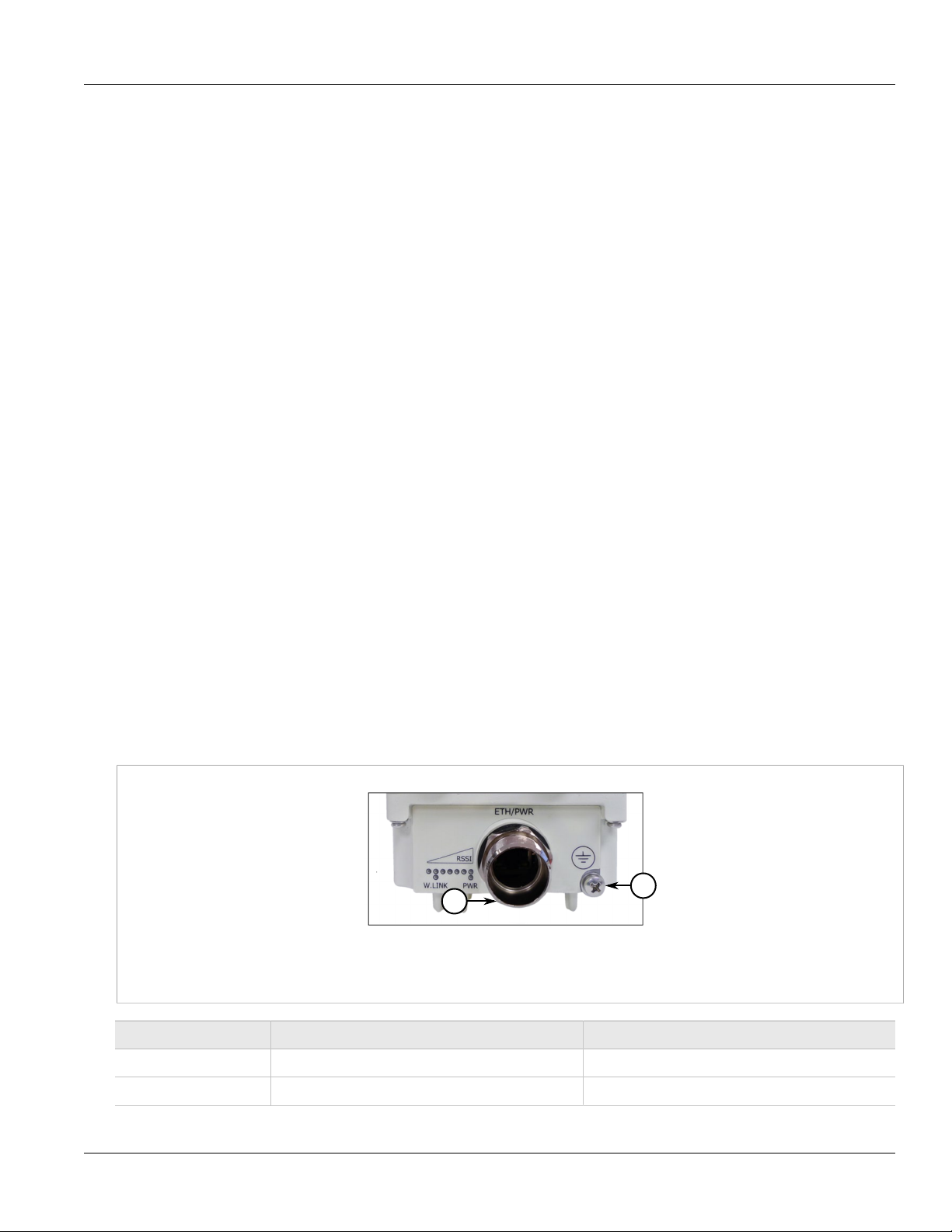
Connectors and LED indicators are found on the bottom of the device casing.
Figure 1: RUGGEDCOM WIN5214 Connectors
1. ETH/PWR 2. Ground
Name Description Connector Type
ETH/PWR Data and power from PoE injector RJ-45
Ground Ground Grounding screw
2 Configuration Ports and Indicator LEDs

RUGGEDCOM WIN5214
Installation Guide
LED Indicators
The LED indicators display the following information:
• RSSI: displays the Received Signal Strength Indicator (RSSI) level
• W.LNK: displays the wireless link indication
• PWR: displays the power status
The following table displays the LED indicators for the device:
LED Color Description
Chapter 1
Introduction
WLNK is ON Green
WLNK is BLINKING Green
PWR is ON Green CPE power is on.
RSSI: one LED is ON (least
significant)
RSSI: two LEDs are ON Green -85 < RSSI < -90
RSSI: three LEDs are ON Green -80 < RSSI < -85
RSSI: four LEDs are ON Green -75 < RSSI < -80
RSSI: five LEDs are ON Green -70 < RSSI < -75
RSSI: six LEDs are ON Green -65 < RSSI < -70
RSSI: seven LEDs are ON
Green RSSI < -90
Older Hardware
LEDs 1-7: Green
LED 8: Red
Latest Hardware
LEDs 1-6: Green
LED 7: Red
The device is connected with and
receives services from the base
station; network entry is complete.
The link between the CPE and the
base station is down.
-20 < RSSI < -60
RSSI: only the last LED is ON
(most significant)
Red -20 < RSSI (Saturation)
RUGGEDCOM WIN1010 Data Adapter LED Indicators
LEDs on the WIN1010 data adapter indicate the status of the WIN1010 power supply.
Name Color Description
PWR Green Input power is connected
LAN Green LAN link/activity display
WLNK Green Wireless link/activity display
Configuration Ports and Indicator LEDs 3
Chapter 1
1
2
3
Introduction
Section 1.3
Antennas
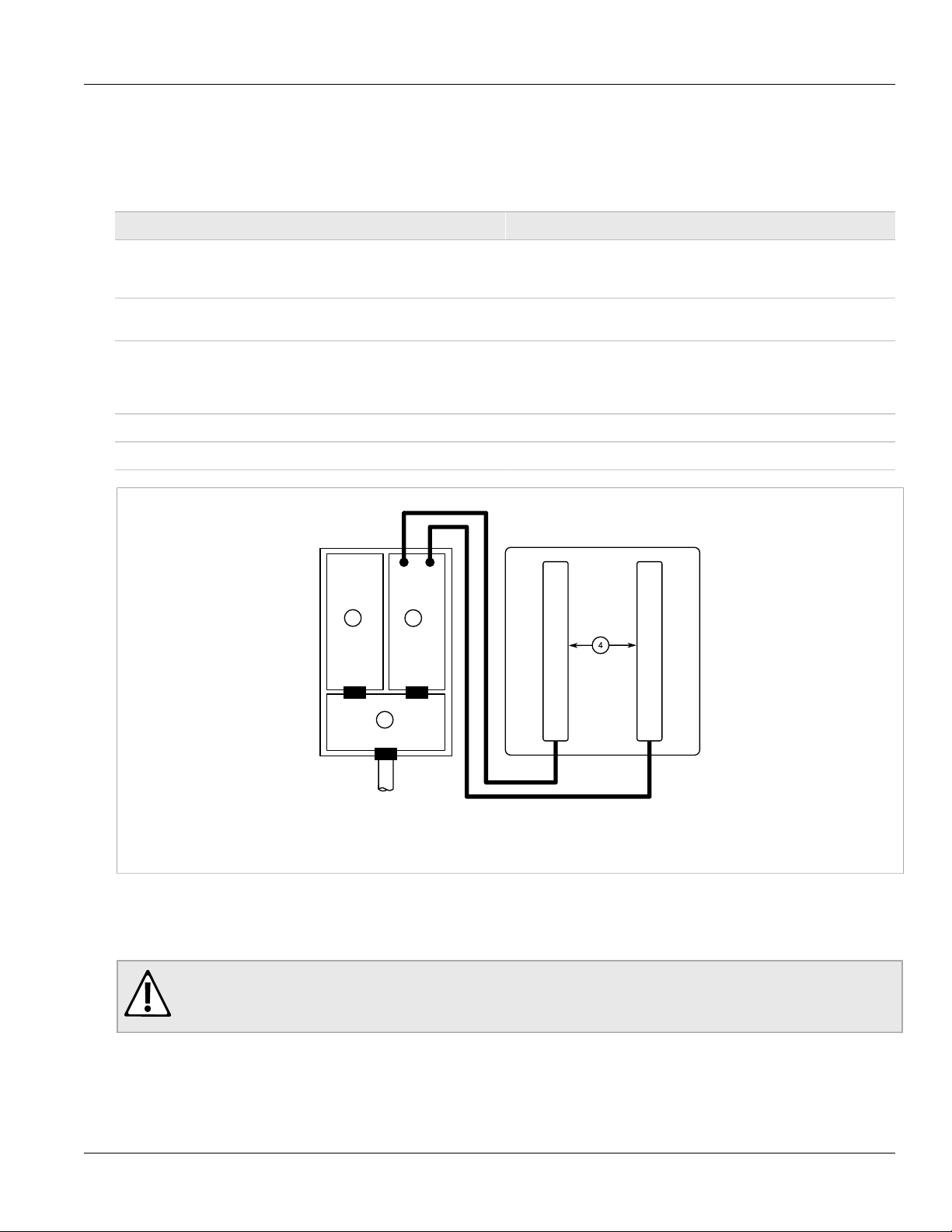
The CPE consists of the following modules:
Module Description
RUGGEDCOM WIN5214
Installation Guide
Base-Band board: Includes the WiMAX 16e MIMO Base-Band SoC and runs the 16e
Power Supply board with DC/DC power supply: Converts 48 VDC input to the voltages feeding the Digital and RF
RF board: Single transmit/dual receive module that modulates the analog
Chassis
Antenna or Antennas: Integrated dual polarization antenna supporting MIMO schemes.
MAC + PHY, user interface, and analog front end interface to the RF
module.
modules.
WiMAX signal input from the Base-Band modem to the high
frequency RF output. Several RF modules exist, each supporting a
different frequency band.
Figure 2: RUGGEDCOM WIN5214 CPE Block Diagram: Integrated Antenna
1. Power Supply 2. RF 3. Base-Band 4. Antennas
Outdoor Grounding System
Verify the antenna or cable system is grounded. The CPE antenna installation must be as per Article 810 of the
NEC.
WARNING!
Fire hazard – risk of serious personal injury and/or damage to equipment. To reduce the risk of fire, use
only 26 AWG or larger telecommunication line cord between indoor and outdoor units.
Specifically, the requirement the grounding conductor be not less than 10 AWG (Cu). The grounding scheme
should either be in accordance with UL 96 and 96A Lightning Protection Components and Installation
Requirements for Lightning Protection Systems, or tested in accordance with UL 50 and UL 497.
4 Antennas

RUGGEDCOM WIN5214
Installation Guide
Chapter 1
Introduction
NOTE
The antenna is an integral part of the device.
Antennas 5

RUGGEDCOM WIN5214
Installation Guide
Chapter 1
Introduction
Antennas 6
 Loading...