

Page 1

FCC Statement And
Cautions
RUGGEDCOM WiN5100/WiN5200
v4.3
User Guide
Introduction
Product Description
Mounting
Installation Procedure
Equipment Configuration
and Monitoring
CPE Management Interface
WiN5100/WiN5200
Specifications
IDU to ODU Cable
Specifications
1
2
3
4
5
6
A
B
11/2013
List of Acronyms
RUGGEDCOM CPE Warranty
C
D
Page 2

RUGGEDCOM WiN5100/WiN5200
User Guide
ii
Page 3

RUGGEDCOM WiN5100/WiN5200
User Guide
Table of Contents
Table of Contents
FCC Statement And Cautions ............................................................................ vii
Chapter 1
Introduction .......................................................................................................... 1
1.1 WiN5100 with External Antenna: Package Components and Unpacking ........................................... 1
1.2 WiN5200 with Integrated Antenna: Package Components and Unpacking ........................................ 1
1.3 Safety Information ........................................................................................................................ 2
1.3.1 RF Exposure ..................................................................................................................... 2
1.3.2 Lightning Protection ........................................................................................................... 2
1.3.3 Power Cord Protection ....................................................................................................... 2
1.3.4 Servicing ........................................................................................................................... 3
1.3.5 Outdoor Grounding System ................................................................................................ 3
1.4 Allowed Antenna Types ................................................................................................................ 3
Chapter 2
Product Description ............................................................................................. 5
2.1 IEEE 802.16e Mobile WiMAX Compliance ..................................................................................... 5
2.2 Block Diagram ............................................................................................................................. 5
2.3 Features ...................................................................................................................................... 7
2.3.1 Mobile WiMAX Wave 2 MIMO Features .............................................................................. 7
2.3.1.1 Space-Time Coding ................................................................................................ 8
2.3.1.2 Time Division Duplexing (TDD) ................................................................................ 9
2.3.1.3 Coding Rate ........................................................................................................... 9
2.3.1.4 Modulation ............................................................................................................. 9
2.3.1.5 Convolution Turbo Coding Correction ....................................................................... 9
2.3.2 Deployment Models ........................................................................................................... 9
2.3.2.1 PTP Deployment .................................................................................................... 9
2.3.2.2 PMP Deployment .................................................................................................. 10
2.3.2.3 Non Line-of-Sight .................................................................................................. 10
2.3.2.4 Channelization ...................................................................................................... 10
2.3.3 Service Flows .................................................................................................................. 10
2.3.3.1 Service Flow Classification .................................................................................... 10
2.3.3.2 Default Service Flows ........................................................................................... 11
2.3.3.3 Scheduling ........................................................................................................... 11
2.3.4 Physical Description ........................................................................................................ 12
iii
Page 4

Table of Contents
2.3.5 Connectors and LED Indicators ........................................................................................ 13
2.3.5.1 WiN5100 Connectors: AC Version ......................................................................... 14
2.3.5.2 WiN5100 Connectors: DC Version ......................................................................... 15
2.3.5.3 WiN5200 Connectors ............................................................................................ 16
2.3.6 LED Indicators ................................................................................................................ 16
Chapter 3
RUGGEDCOM WiN5100/WiN5200
Mounting ............................................................................................................ 19
3.1 Site Survey ................................................................................................................................ 19
3.1.1 Recommended Site Requirements .................................................................................... 19
3.1.2 Pole Mounting ................................................................................................................. 19
3.1.3 Wall Mounting ................................................................................................................. 19
Chapter 4
Installation Procedure ........................................................................................ 21
4.1 Safety Hazards .......................................................................................................................... 21
4.2 Required Installation Tools .......................................................................................................... 21
4.3 Required Cables ........................................................................................................................ 21
4.4 Cat5 Cable Requirements ........................................................................................................... 22
4.5 Mounting Bracket Installation ...................................................................................................... 22
4.6 Pole Mount Installation ............................................................................................................... 24
4.7 Wall Mount Installation ............................................................................................................... 25
4.8 Connecting the Ground Cable ..................................................................................................... 27
4.9 Aligning the CPE Antenna .......................................................................................................... 27
4.10 Cable Connections ................................................................................................................... 28
4.10.1 Weatherproofing ............................................................................................................ 28
4.10.1.1 Weatherproofing Cable Connections .................................................................... 28
4.10.2 Assembling the RJ45 Connector ..................................................................................... 30
4.10.3 Installing the WiN1010 Data Adaptor .............................................................................. 34
4.10.4 WiN1010 Data Adaptor LED Indicators ........................................................................... 35
4.11 Hazardous Location Installation ................................................................................................. 35
User Guide
Chapter 5
Equipment Configuration and Monitoring .......................................................... 37
5.1 Connecting to and Logging In to the CPE .................................................................................... 37
5.2 Configuring the CPE .................................................................................................................. 39
Chapter 6
CPE Management Interface .............................................................................. 43
6.1 Using the CPE Management Interface ......................................................................................... 43
6.1.1 Configuration Buttons ...................................................................................................... 44
6.2 System Management .................................................................................................................. 45
iv
Page 5

RUGGEDCOM WiN5100/WiN5200
User Guide
6.2.1 Managing System Functions ............................................................................................ 46
6.2.2 Changing the CPE Management Interface Password ......................................................... 47
6.2.3 Users and Access Levels ................................................................................................. 48
6.2.4 Loading HTTPS Certificates and Private Keys ................................................................... 49
6.2.5 Generating SSH Keys ...................................................................................................... 50
6.2.6 Log Management ............................................................................................................ 51
6.2.7 Remote Management Parameters .................................................................................... 51
6.2.8 Software Version Management ......................................................................................... 54
6.2.9 SNMP Administration ....................................................................................................... 62
6.2.10 Alarms & Traps ............................................................................................................. 67
6.2.11 NTP Server ................................................................................................................... 71
6.2.12 Developer Mode ............................................................................................................ 72
6.2.13 Ethernet Lock ................................................................................................................ 72
6.2.14 Radius Login ................................................................................................................. 73
6.3 CPE Network Configuration ........................................................................................................ 74
6.3.1 Network IP Settings ........................................................................................................ 74
6.3.2 Ethernet Settings ............................................................................................................. 76
6.3.3 Configuring the Access List .............................................................................................. 79
6.4 CPE Statistics ............................................................................................................................ 80
6.4.1 General Statistics ............................................................................................................ 80
6.4.2 Device Info ...................................................................................................................... 82
6.4.3 RF Statistics .................................................................................................................... 82
Table of Contents
6.2.3.1 Adding Users ........................................................................................................ 48
6.2.7.1 Configuring the Management Port .......................................................................... 52
6.2.7.2 Configuring the Management VLAN ....................................................................... 52
6.2.7.3 Configuring DSCP Marking .................................................................................... 53
6.2.8.1 Upgrading CPE Software ...................................................................................... 54
6.2.8.2 Viewing Software Properties .................................................................................. 55
6.2.8.3 Downloading CPE Software ................................................................................... 56
6.2.8.4 Managing the Primary Memory Bank ..................................................................... 57
6.2.8.5 Managing the Secondary Memory Bank ................................................................. 59
6.2.8.6 File Status ............................................................................................................ 61
6.2.9.1 SNMP General Settings ........................................................................................ 62
6.2.9.2 SNMPv2 Configuration .......................................................................................... 63
6.2.9.3 SNMPv3 Configuration .......................................................................................... 64
6.2.9.4 Viewing SNMPv3 Access Groups .......................................................................... 66
6.2.9.5 MIB2 System ........................................................................................................ 66
6.3.2.1 Configuring VLAN Tagging .................................................................................... 76
6.3.2.2 Configuring the MAC Address Table ....................................................................... 77
6.3.2.3 MTU Configuration ................................................................................................ 78
v
Page 6

Table of Contents
6.4.4 Network Statistics ............................................................................................................ 84
6.4.5 Service Flow Statistics ..................................................................................................... 85
6.5 WiMAX Settings ......................................................................................................................... 86
6.5.1 Scanner Settings ............................................................................................................. 86
6.5.2 WiMAX Authentication ..................................................................................................... 88
6.5.2.1 Viewing the CPE Authentication Method ................................................................. 88
6.5.2.2 Configuring EAP-TLS Authentication ...................................................................... 89
6.5.2.3 Configuring EAP-TTLS Authentication .................................................................... 90
6.5.2.4 Configuring Null Authentication .............................................................................. 91
6.5.2.5 Loading Authentication Certificates ........................................................................ 91
6.5.3 Viewing Base Station Information ..................................................................................... 92
6.5.4 Configuring WiMAX Radio Parameters .............................................................................. 93
Appendix A
RUGGEDCOM WiN5100/WiN5200
WiN5100/WiN5200 Specifications ..................................................................... 95
Appendix B
IDU to ODU Cable Specifications ...................................................................... 99
User Guide
Appendix C
List of Acronyms ............................................................................................... 101
Appendix D
RUGGEDCOM CPE Warranty ......................................................................... 105
vi
Page 7
RUGGEDCOM WiN5100/WiN5200
User Guide
FCC Statement And Cautions
FCC Statement And Cautions
Federal Communications Commission Radio Frequency Interference Statement
This equipment has been tested and found to comply with the limits for a Class A digital device pursuant to Part
15 of the FCC Rules. These limits are designed to provide reasonable protection against harmful interference
when the equipment is operated in a commercial environment. This equipment generates, uses and can radiate
radio frequency energy and, if not installed and used in accordance with the instruction manual, may cause
harmful interference to radio communications. Operation of this equipment in a residential area is likely to cause
harmful interference in which case the user will be required to correct the interference at his own expense.
CAUTION!
Caution: Service
This product contains no user-serviceable parts. Attempted service by unauthorized personnel shall
render all warranties null and void.
Changes or modifications not expressly approved by RUGGEDCOM could invalidate specifications,
test results, and agency approvals, and void the user’s authority to operate the equipment.
Should this device require service, refer to Appendix D, RUGGEDCOM CPE Warranty in this guide.
CAUTION!
Caution: Physical Access
This product should be installed in a restricted access location where access can only be gained by
service personnel or users who have been instructed about the reasons for the restrictions applied to
the location and about any precautions that shall be taken; and access is through the use of a tool or
lock and key, or other means of security, and is controlled by the authority responsible for the location.
vii
Page 8

RUGGEDCOM WiN5100/WiN5200
User Guide
FCC Statement And Cautions
viii
Page 9
RUGGEDCOM WiN5100/WiN5200
User Guide
Introduction
This guide describes how to install and configure the RUGGEDCOM WiN5100-series and WiN5200-series Out
Door Unit (ODU) Customer Premises Equipment (CPE) units. The WiN5100-series and WiN5200-series ODU
CPEs are members of the RUGGEDCOM family, a line of WiMAX broadband wireless access systems based on
the 802.16e mobile WiMAX standard.
This guide is intended for installers and network operators. This manual assumes that users have some
experience with WiMAX technologies and procedures.
NOTE
While some safety precautions are reviewed here, this guide assumes that installers are trained in safe
installation practises. Users who are new to WiMAX technologies and service procedures should not
rely on this guide for comprehensive guidance.
Section 1.1
Chapter 1
Introduction
WiN5100 with External Antenna: Package Components and Unpacking
• 1 × WiN5100-series ODU CPE with external antenna connectors
• RF cables - 5m (approximately 16')
• Power cable - 5m (approximately 16')
• Mounting kit
Section 1.2
WiN5200 with Integrated Antenna: Package Components and Unpacking
• 1 × WiN5200-series ODU CPE with integrated directional dual slant antenna
• 1 × commercial grade power supply
WiN5100 with External Antenna: Package Components
and Unpacking 1
Page 10
Chapter 1
Introduction
Section 1.3
RUGGEDCOM WiN5100/WiN5200
Safety Information
Section 1.3.1
RF Exposure
The WiN5100-series and WiN5200-series ODU CPEs are compliant with the requirements set forth in CFR
47, section 1.1307, addressing Radio Frequency (RF) exposure from radio frequency devices as defined in
OET Bulletin 65. The emitted radiation should be as little as possible. To achieve minimum RF exposure, install
the CPE when it is configured not to transmit and set it to operational mode remotely, rather than enabling
transmission by the installer on-site. For maintenance of the CPE, or other operations which require RF
exposure, minimize the exposure time according to the regulations set by the FCC or the regulations relevant to
the country of installation.
For WiN5149/WiN5249 and WiN5158/WiN5258, always install the antenna at least 0.65 m from people and
public areas. For other models, always install the antenna at least 0.39 m from people and public areas.
User Guide
Section 1.3.2
Lightning Protection
When the ODU CPE is installed in an outdoor location, all indoor components (Ethernet connections and power
supply) should be connected through a lightning protector.
Lightning protection is intended to protect people and equipment located indoors from lightning that might strike
the ODU CPE or its outdoor cables. The lightning protection device should be installed indoors, as close as
possible to the point where the cables enter the building. The lightning protector can be installed outdoors as
long as the cables leading from it to indoor equipment are well protected from lightning between the box and the
building entrance.
Section 1.3.3
Power Cord Protection
The ODU CPE should always be connected to a supported Power over Ethernet (PoE) injector.
NOTE
The WiN5100-series and WiN5200-series ODU CPEs are non-standard PoE devices. Do not attempt
to use third-party PoE injectors. The use of any other type of connection or application of the ODU CPE
and/or WiN1010 data adaptor is not permitted.
Route all power supply cords so that people cannot walk on them or place objects on or against them, which can
pinch or damage the cords.
2 Safety Information
Page 11
RUGGEDCOM WiN5100/WiN5200
User Guide
Section 1.3.4
Servicing
Do not open the ODU CPE cover to perform corrective actions unless instructed to do so in the operating
instructions.
Section 1.3.5
Outdoor Grounding System
NOTE
For the WiN5200, the antenna is an integral part of the CPE.
Verify that the antenna or cable system is grounded. The CPE antenna installation must be as per Article 810 of
the NEC. Of particular note is the requirement that the grounding conductor be not less than 10 AWG (Cu). The
grounding scheme should either be in accordance with UL 96 and 96A Lightning Protection Components and
Installation Requirements for Lightning Protection Systems, or tested in accordance with UL 50 and UL 497.
WARNING!
To reduce the risk of fire, use only 26 AWG or larger telecommunication line cord between indoor and
outdoor units.
Chapter 1
Introduction
Section 1.4
Allowed Antenna Types
NOTE
Under Industry Canada regulations, this radio transmitter may only operate using an antenna of a type
and maximum (or lesser) gain approved for the transmitter by Industry Canada. To reduce potential
radio interference to other users, the antenna type and its gain should be so chosen that the equivalent
isotropically radiated power (e.i.r.p.) is not more than that necessary for successful communication.
This radio transmitter (WIN5149-AC, WIN5149-DC, WIN5249, WIN5158-AC, WIN5158-DC, WIN5258)
has been approved by Industry Canada to operate with the antenna types listed below with the
maximum permissible gain and required antenna impedance for each antenna type indicated. Antenna
types not included in this list, having a gain greater than the maximum gain indicated for that type, are
strictly prohibited for use with this device.
Conformément à la réglementation d'Industrie Canada, le présent émetteur radio peut fonctionner
avec une antenne d'un type et d'un gain maximal (ou inférieur) approuvé pour l'émetteur par Industrie
Canada. Dans le but de réduire les risques de brouillage radioélectrique à l'intention des autres
utilisateurs, il faut choisir le type d'antenne et son gain de sorte que la puissance isotrope rayonnée
équivalente (p.i.r.e.) ne dépasse pas l'intensité nécessaire à l'établissement d'une communication
satisfaisante.
Le présent émetteur radio (WIN5149-AC, WIN5149-DC, WIN5249, WIN5158-AC, WIN5158-DC,
WIN5258) a été approuvé par Industrie Canada pour fonctionner avec les types d'antenne énumérés
ci-dessous et ayant un gain admissible maximal et l'impédance requise pour chaque type d'antenne.
Les types d'antenne non inclus dans cette liste, ou dont le gain est supérieur au gain maximal indiqué,
sont strictement interdits pour l'exploitation de l'émetteur.
Servicing 3
Page 12

Chapter 1
RUGGEDCOM WiN5100/WiN5200
Introduction
The following table contains a list of approved 4.9/5.8Ghz antenna types for the following models: WiN5149-AC,
WiN5149-DC, WiN5249, WiN5158-AC, WiN5158-DC, and WiN5258.
Table: Antenna Types
Type Manufacturer Model Number Gain Impedance
Dual slant antenna MTI Wireless Edge Ltd. MT-465017/SVH/E 22.5 dBi 50Ω
Dual slant antenna MTI Wireless Edge Ltd. MT-465017/NVH 22.5 dBi 50Ω
Omnidirectional MTI Wireless Edge Ltd. MT 462008/N/A 9.5 dBi 50Ω
User Guide
Omnidirectional HUBER-SUHNER
SWA-0860/360/4/0/V_2,
1399.17.0099
9.5 dBi 50Ω
For WCS CPE 2.3GHz, to comply with FCC regulations and restrictions, use only outdoor antennas with gain of
16dBi.
4 Allowed Antenna Types
Page 13

RUGGEDCOM WiN5100/WiN5200
User Guide
Product Description
Product Description
The WiN5100-series and WiN5200-series Out Door Unit (ODU) Customer Premises Equipment (CPE) units are
IEEE 802.16-2005 compliant wireless devices for the deployment of point-to-multipoint (PMP) and point-to-point
(PTP) network architectures.
The ODU CPEs are WiMAX Forum 802.16e Wave 2 (MIMO) certified subscribers. Each subscriber registers and
establishes a bi-directional data link with the base station.
NOTE
This device complies with Industry Canada license-exempt RSS standard. Operation is subject to the
following two conditions:
• this device may not cause interference, and
• this device must accept any interference, including interference that may cause undesired operation
of the device.
Le présent appareil est conforme aux CNR d'Industrie Canada applicables aux appareils radio
exempts de licence. L'exploitation est autorisée aux deux conditions suivantes :
• l'appareil ne doit pas produire de brouillage, et
• l'utilisateur de l'appareil doit accepter tout brouillage radio électrique subi, meme si le brouillage est
susceptible d'en compromettre le fonctionnement.
Chapter 2
Section 2.1
IEEE 802.16e Mobile WiMAX Compliance
The IEEE 802.16-2005 specifications describe a PMP broadband wireless access standard for systems. This
standard includes descriptions for both the Media Access Control (MAC) and the physical (PHY) layers.
The ODU CPE is compliant to IEEE 802.16-2005 WiMAX forum Wave 2 profile.
NOTE
The 802.16e standards are subject to amendment and the WiN5100/WiN5200 product family design
compliance applies to a specific revision of the standard. The WiN5100/WiN5200 product family does
not support mesh communication (direct subscriber-to-subscriber).
Section 2.2
Block Diagram
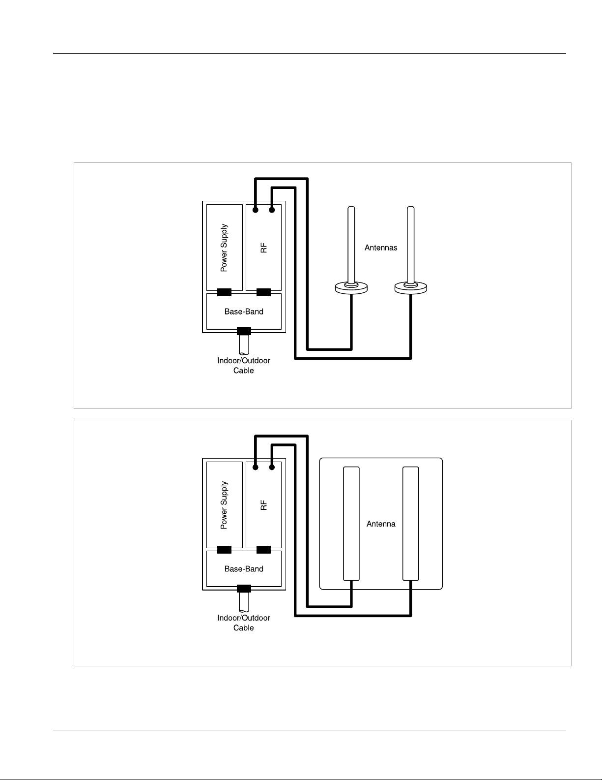
The CPE consists of the following modules:
1. Base-Band board: includes the the WiMAX 16e MIMO Base-Band SoC and runs the 16e MAC + PHY, user
interface, and analog front end interface to the RF module.
2. Power Supply board with DC/DC power supply: converts 48 VDC input to the voltages feeding the Digital
and RF modules.
IEEE 802.16e Mobile WiMAX Compliance 5
Page 14
Chapter 2
Product Description
RUGGEDCOM WiN5100/WiN5200
3. RF board: single transmit/dual receive module that modulates the analog WiMAX signal input from the
Base-Band modem to the high frequency RF output. Several RF modules exist, each supporting a different
frequency band.
4. Chassis
5. Antenna or Antennas: dual omni or polarization antennas (WiN5100) or integrated dual polarization antenna
(WiN5200) supporting MIMO schemes.
User Guide
Figure 1: WiN5100 CPE Block Diagram: External Antennas
Figure 2: WiN5200 CPE Block Diagram: Integrated Antenna
6 Block Diagram
Page 15

RUGGEDCOM WiN5100/WiN5200
User Guide
Section 2.3
Product Description
Features
Section 2.3.1
Mobile WiMAX Wave 2 MIMO Features
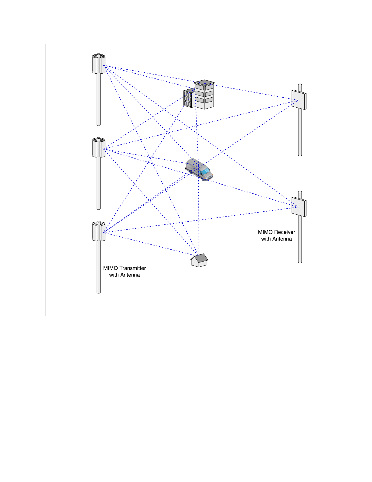
Multiple-Input, Multiple-Output (MIMO) describes systems that use more than one radio and antenna system
at each end of the wireless link. In the past it was too costly to incorporate multiple antennas and radios in a
subscriber terminal. Recent advances in radio miniaturization and integration technology now make it feasible
and cost effective. Combining two or more received signals has the immediate benefit of improving received
signal strength, but MIMO also enables transmission of parallel data streams for greater throughput. For
example, in a 2 × 2 MIMO (two transmit and two receive elements), dual polarization point-to-point system, the
carrier’s allocated frequency can be used twice, effectively doubling the throughput data rate.
In point-to-multipoint systems employing MIMO, each base station antenna transmits a different data stream
and each subscriber terminal receives various components of the transmitted signals with each of its subscriber
antennas. The subscriber terminal is able to algorithmically separate and decode the parallel simultaneously
received data streams.
Chapter 2
Features 7
Page 16
Chapter 2
Product Description
RUGGEDCOM WiN5100/WiN5200
User Guide
Figure 3: MIMO Antenna System
Section 2.3.1.1
Space-Time Coding
Space-Time Coding (STC) is a technique for implementing transmission diversity. Mobile WiMAX uses transmit
diversity in the downlink direction to provide spatial diversity to enhance the signal quality to a specific subscriber
located anywhere within the range of the antenna beam. Although providing less signal gain than beam-forming,
transmit diversity is more robust for mobile users as it does not require prior knowledge of the path characteristics
of a subscriber’s particular frequency channel. One such STC technique, known as the Alamouti Code, was
published in 1998[4] is incorporated in the WiMAX 16e standard.
8 Space-Time Coding
Page 17

RUGGEDCOM WiN5100/WiN5200
User Guide
Section 2.3.1.2
Product Description
Time Division Duplexing (TDD)
The CPE uses time division duplexing (TDD) to transmit and receive on the same RF channel. This is a noncontention based method for providing an efficient and predictable two-way PTP or PMP cell deployment. All
uplink and downlink transmission scheduling is managed by the base station. The base station sends data traffic
to subscribers, polls for grant requests, and sends grant acknowledgements based on the total of all traffic to all
subscribers.
Section 2.3.1.3
Coding Rate
Each burst of data transmitted over the wireless interface is padded with redundant information, making it more
resistant to potential over-the-air errors. The coding rate is the ratio of user data to the total data transmitted
including the redundant error correction data. The base station supports coding rates of 1/2, 2/3, and 3/4.
Section 2.3.1.4
Modulation
Chapter 2
The modulation technique specifies how the data is coded within the OFDMA carriers. The base station supports
QPSK, 16 Quadarature Amplitude Modulation (QAM), and 64 QAM modulations.
Section 2.3.1.5
Convolution Turbo Coding Correction
Convolution Coding (CC) error correction is enabled for all traffic rates. This low-level process can correct bursts
of errors in received messages and reduce the number of retransmissions.
Section 2.3.2
Deployment Models
The CPE supports point to point (PTP) and point to multipoint (PMP) deployment scenarios.
Section 2.3.2.1
PTP Deployment
When deployed in a PTP configuration, the base station establishes a dedicated bidirectional link to a single
subscriber. PTP deployments typically use a directional narrow beam antenna for both ends of the link.
Time Division Duplexing (TDD) 9
Page 18

Chapter 2
Product Description
Section 2.3.2.2
RUGGEDCOM WiN5100/WiN5200
PMP Deployment
When deployed in a PMP configuration, the base station establishes bi-directional links to more than one
subscriber. PMP deployments typically use a wide beam (sector) antenna at the base station and a narrow beam
antenna at the subscriber. Service flows are used to police service level agreements for each subscriber.
Section 2.3.2.3
Non Line-of-Sight
The WiN5100/WiN5200 product family supports line-of-sight (LOS) and non line-of-sight (NLOS) operation. A
clear LOS link has no obstacles within 60% of the first Fresnel zone of the direct path.
A wireless link is considered non-LOS if natural or man-made structures block the visible path between the
base station and the subscriber. In this case, a wireless link can be established only if a reflective path can be
established between the base station and subscriber.
Section 2.3.2.4
Channelization
User Guide
The CPE is a frequency-specific system, with the frequency band defined by the PHY unit. The use of the
operating band must be in accordance with local regulation requirements.
The CPE divides the available frequency band into channels. Allocation of channels during deployment is
dependent on spectrum availability in the licensed band and local licensing requirements and conditions. Channel
selection allows planners to obtain the maximum geographic coverage, while avoiding frequency contention in
adjacent sectors.
Section 2.3.3
Service Flows
Service flows are a key feature of the 802.16e standard. A service flow represents a unidirectional data flow
having separate Quality of Service (QoS) settings for uplink and downlink. Service flows provide the ability to set
up multiple connections to each subscriber in a sector.
Separate service flows can be established for uplink and downlink traffic, where each service flow is assigned
a unique service level category and separate QoS settings. This feature allows segregation of high-speed/highpriority traffic from less time-critical flows.
Section 2.3.3.1
Service Flow Classification
Data packets are forwarded based on classification rules. Classification rules examine each packet for pattern
matches such as destination address, source address, IP TOS, or VLAN tag. All classification is defined at the
base station and the classification parameters are downloaded to the subscriber.
10 PMP Deployment
Page 19

RUGGEDCOM WiN5100/WiN5200
User Guide
Section 2.3.3.2
Product Description
Default Service Flows
Default uplink and downlink service flows are created automatically for each registered subscriber. These service
flows are used to pass all traffic not matching any user-defined service flow (such as broadcast ARP) between
the base station and subscribers. The default service flow capacity is limited for each subscriber.
Section 2.3.3.3
Scheduling
The base station enforces QoS settings for each service flow by controlling all uplink and downlink traffic
scheduling. This provides a non-contention based traffic model with predictable transmission characteristics. By
analyzing the total of all requests from all subscribers, the base station ensures that uplink and downlink traffic
conforms to the current service level agreements (SLAs). Centralized scheduling increases predictability of traffic,
eliminates contention, and provides the maximum opportunity for reducing overhead.
A regular period is scheduled for subscribers to register with the base station. These subscribers may be newly
commissioned or have been deregistered due to service outage or interference on the wireless interface. This is
the only opportunity for multiple subscribers to transmit simultaneously.
• Real-Time Polling Service (rt-PS)
Chapter 2
The base station schedules a continuous regular series of transmit opportunities for the subscriber to
send variable size data packets. The grant size is based on the current data transfer requirement. Typical
applications include streaming MPEG video or VOIP with silence suppression. This is efficient for applications
that have a real-time component and continuously changing bandwidth requirements.
• Extended Real-Time Polling Service (ert-PS)
The base station schedules a continuous series of transmit opportunities for the subscriber to send variable
size data packets. This schedule supports real-time applications including VoIP with silence suppression. The
dynamically scheduled grants guarantee reserved bandwidth and reduce latency introduced by repetitive grant
requests. The service flow will not transmit packets larger than the nominal grant interval.
• Non-Real-Time Polling Service (nrt-PS)
The base station schedules regular transmit opportunities for the subscriber to send variable size data packets.
Typical applications include high bandwidth FTP. The polling period is typically be one second or less, even
during periods of network congestion.
• Best Effort (BE)
The base station schedules transmit opportunities for the subscriber to send traffic based on unused bandwidth
after all higher level traffic scheduling requirements are serviced. Typical applications include Internet access
and email. Best effort service flows can be assigned a priority of 0 to 7.
• Unsolicited Grant Service (UGS)
The base station schedules a continuous series of transmit opportunities for the subscriber to send fixed size
data packets. This schedule supports real-time applications, including VoIP or TDM transport. The UGS prescheduled grants guarantee reserved bandwidth and reduce latency introduced by repetitive grant requests.
The service flow will not transmit packets larger than the nominal grant interval.
Default Service Flows 11
Page 20
Chapter 2
Product Description
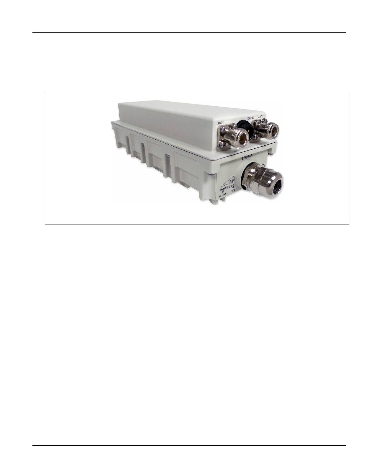
Section 2.3.4
Physical Description
Dimensions (H × W × D without antenna): 22cm × 9.2cm × 6cm
Weight: <1.5 Kg
RUGGEDCOM WiN5100/WiN5200
User Guide
Figure 4: WiN5100: General View
12 Physical Description
Page 21

RUGGEDCOM WiN5100/WiN5200
User Guide
Product Description
Chapter 2
Figure 5: WiN5200: Top View
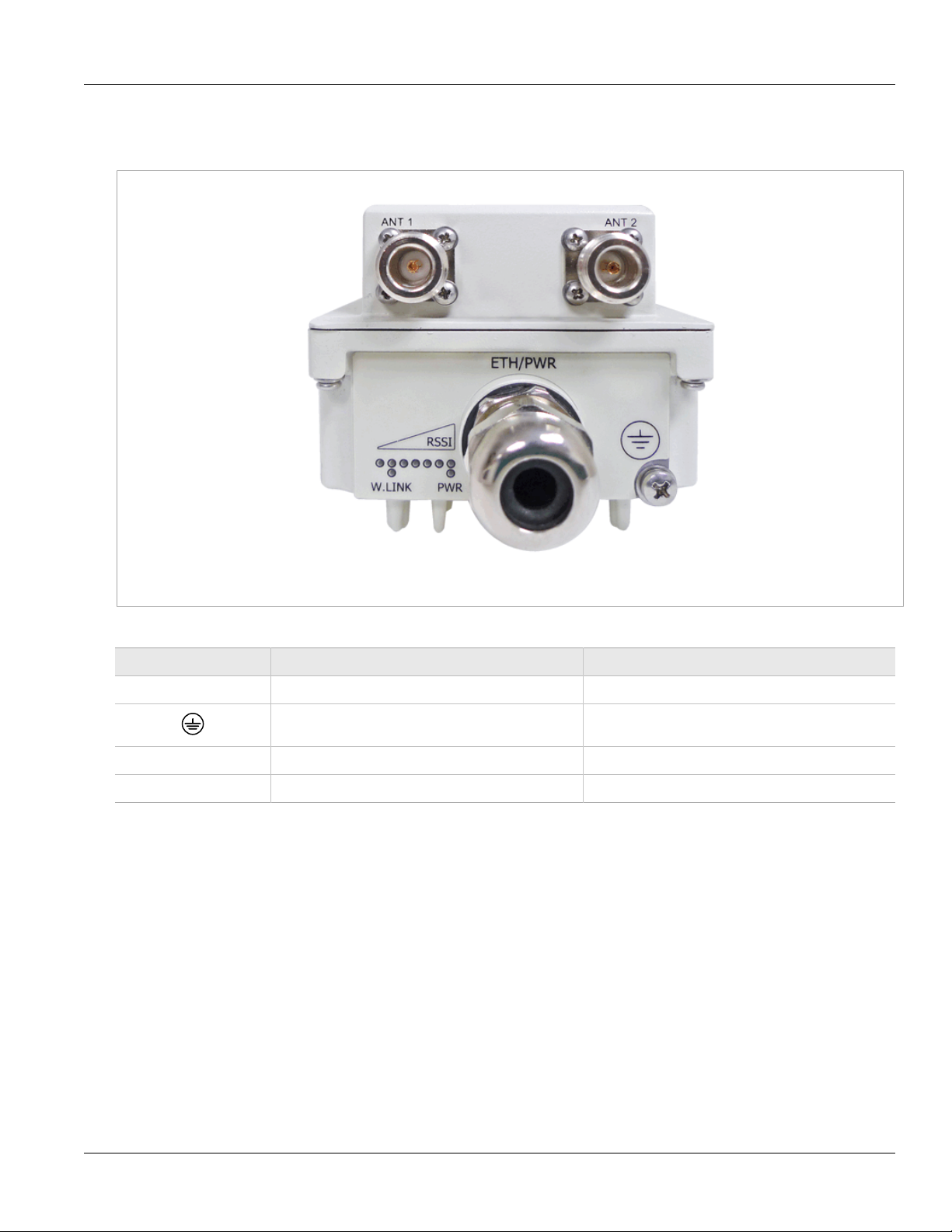
Section 2.3.5
Connectors and LED Indicators
Connectors and LED indicators are found on the bottom of the CPE casing.
Connectors and LED Indicators 13
Page 22
Chapter 2
Product Description
Section 2.3.5.1
WiN5100 Connectors: AC Version
RUGGEDCOM WiN5100/WiN5200
User Guide
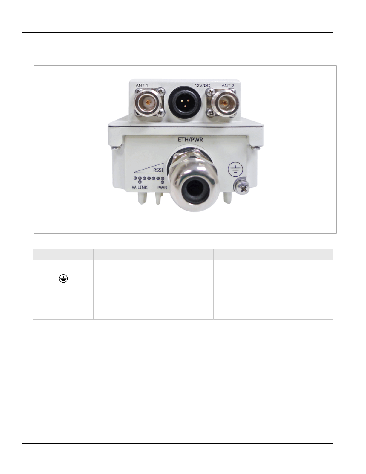
Figure 6: WiN5100 Connectors: AC Version
Table: WiN5100 Connectors: AC Version
Name Description Connector Type
ETH/PWR Data and power from PoE injector RJ-45
ANT1 Antenna 1 RF
ANT2 Antenna 2 RF
Ground Grounding screw
14 WiN5100 Connectors: AC Version
Page 23
RUGGEDCOM WiN5100/WiN5200
User Guide
Section 2.3.5.2
WiN5100 Connectors: DC Version
Product Description
Chapter 2
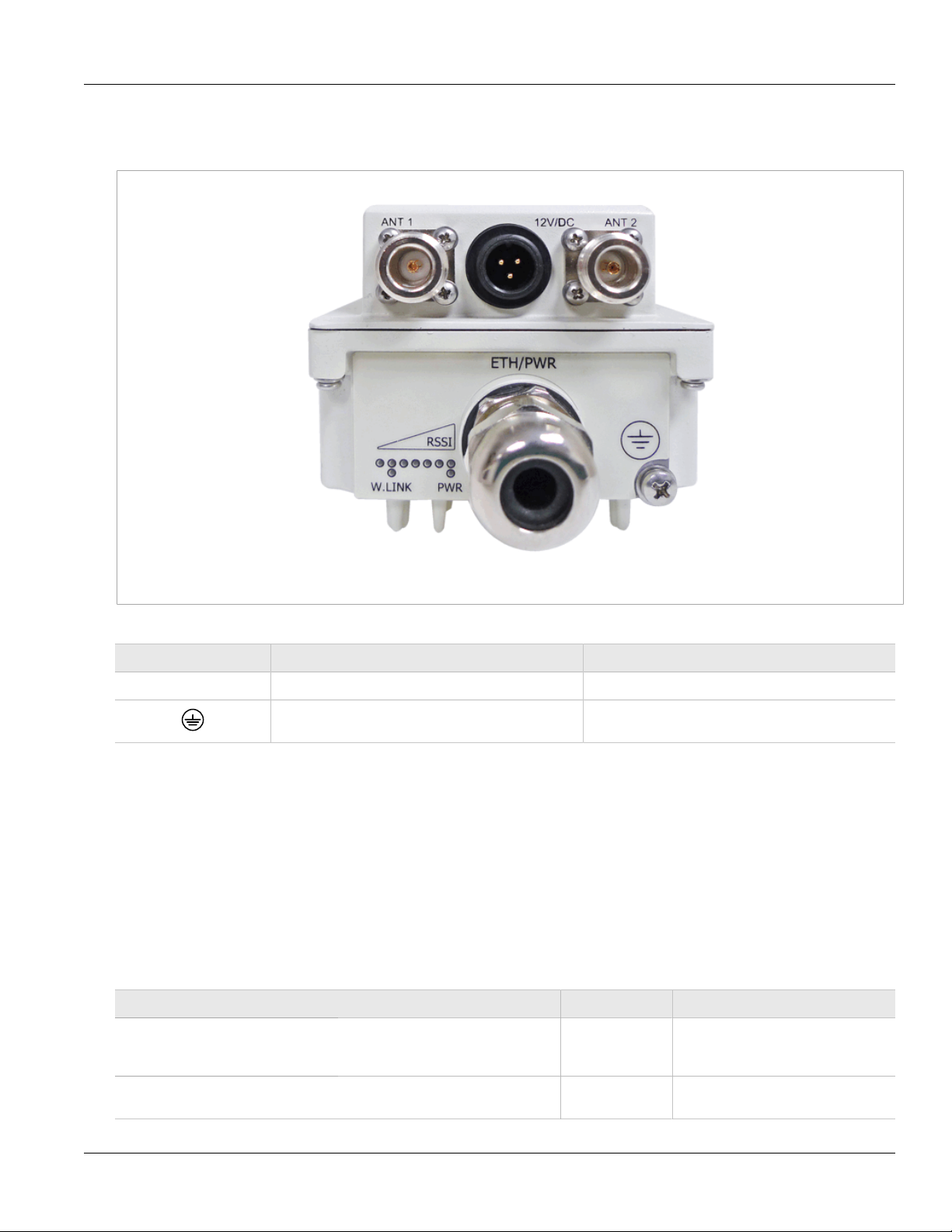
Figure 7: WiN5100 Connectors: DC Version
Table: WiN5100 Connectors: DC Version
Name Description Connector Type
ETH/PWR Ethernet data connection only RJ-45
ANT1 Antenna 1 RF
ANT2 Antenna 2 RF
DC DC input, 10 VDC to 30 VDC 3-pin connector
Ground Grounding screw
WiN5100 Connectors: DC Version 15
Page 24
Chapter 2
Product Description
Section 2.3.5.3
WiN5200 Connectors
RUGGEDCOM WiN5100/WiN5200
User Guide
Figure 8: WiN5200 Connectors
Table: WiN5200 Connectors
Name Description Connector Type
ETH/PWR Data and power from PoE injector RJ-45
Ground Grounding screw
Section 2.3.6
LED Indicators
The LED indicators at the bottom of the CPE casing display the following information:
• RSSI: displays the RSSI level
• W.LNK: displays the wireless link indication
• PWR: displays the power status
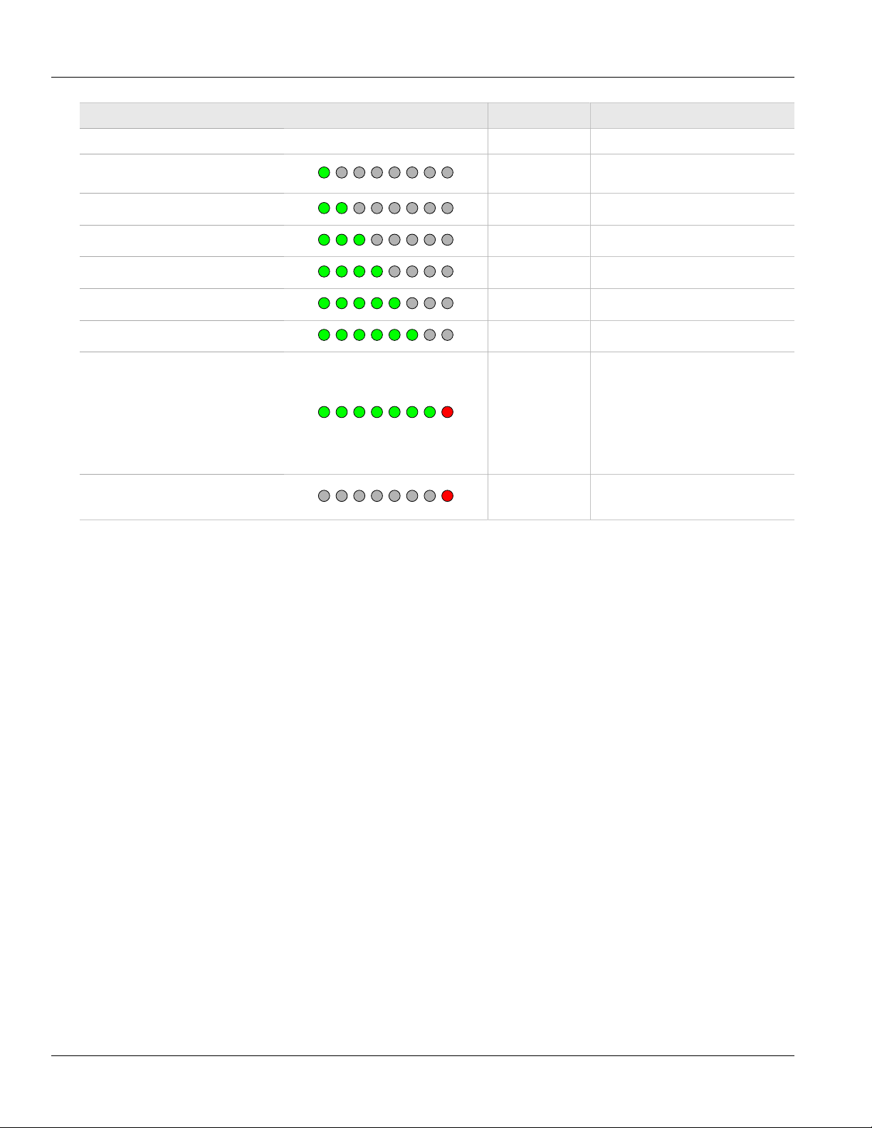
Table: CPE LED Indicators
LED Color Description
WLNK is ON Green
CPE is connected with and receives
services from the base station;
network entry is complete.
WLNK is BLINKING Green
16 WiN5200 Connectors
Link between CPE and base station is
down.
Page 25
RUGGEDCOM WiN5100/WiN5200
User Guide
LED Color Description
PWR is ON Green CPE power is on.
Product Description
Chapter 2
RSSI: one LED is ON (least
significant)
Green RSSI < -90
RSSI: two LEDs are ON Green -85 < RSSI < -90
RSSI: three LEDs are ON Green -80 < RSSI < -85
RSSI: four LEDs are ON Green -75 < RSSI < -80
RSSI: five LEDs are ON Green -70 < RSSI < -75
RSSI: six LEDs are ON Green -65 < RSSI < -70
Older Hardware
LEDs 1-7: Green
RSSI: seven LEDs are ON
LED 8: Red
Latest Hardware
-20 < RSSI < -60
LEDs 1-6: Green
LED 7: Red
RSSI: only the last LED is ON
(most significant)
Red -20 < RSSI (Saturation)
LED Indicators 17
Page 26

RUGGEDCOM WiN5100/WiN5200
User Guide
Product Description
Chapter 2
LED Indicators 18
Page 27

RUGGEDCOM WiN5100/WiN5200
User Guide
Mounting
The WiN5100/WiN5200 ODU CPE mounting kit allows for pole or wall mounting.
When choosing the mounting location for the unit, consider the available mounting structures and antenna
clearance.
Section 3.1
Site Survey
Most wireless networks include many CPEs and BSTs installed in various locations in an overlapping radiocell pattern. It is important to position each CPE at an optimal location considering the assignment of its radio
channels. Therefore, a site survey becomes an essential first step before physically deploying the WiN5100/
WiN5200 solution.
Installation of the CPEs requires a backhaul connection to interface with the corporate network or Internet. The
backhaul connection can be an Ethernet-wired connection, a wireless–connection, or a third party solution.
The site survey should include a detailed planning of the WiMAX system deployment. The system deployment
plan should include mounting points and the routes for the power and backhaul cables.
Chapter 3
Mounting
Section 3.1.1
Recommended Site Requirements
It is highly recommended that the WiN5100/WiN5200 CPEs be mounted near the edge of the roof of a tall
building. The CPEs should be pointed in the direction of the area to be covered. To provide maximum coverage,
multiple CPEs can be installed on the same rooftop. To prevent interference between the units themselves, it is
important to leave some distance between each unit. When choosing the ideal location, it is also important to take
into consideration the overall area topology.
Section 3.1.2
Pole Mounting
You can attach the WiN5100 and WiN5200 to any pipe or pole with a diameter of 1.75" to 10".
Section 3.1.3
Wall Mounting
You can attach the WiN5100 and WiN5200 to any wall capable of carrying the weight of the unit. An outer wall on
a roof or other high location to avoid interference from other buildings or trees is preferred.
Site Survey 19
Page 28

RUGGEDCOM WiN5100/WiN5200
User Guide
Chapter 3
Mounting
Wall Mounting 20
Page 29
RUGGEDCOM WiN5100/WiN5200
User Guide
Installation Procedure
Section 4.1
Safety Hazards
WARNING!
Installing the WiN5100/WiN5200 ODU CPEs can pose a serious hazard. Be sure to take precautions to
avoid the following:
• Exposure to high voltage lines during installation
• Falls when working at heights or with ladders
• Injuries from dropping tools
• Contact with AC wiring
During antenna installation, observe the following:
Installation Procedure
Chapter 4
• For WiN5149/WiN5249 and WiN5158/WiN5258, always install the antenna at least 0.65 m from
people and public areas. For other models, always install the antenna at least 0.39 m from people
and public areas.
• Antenna must be in a fixed position.
• After it is installed, do not change the antenna position.
Section 4.2
Required Installation Tools
• Flat screwdriver
• Wrench or socket set
• Torque wrench
• Drill
• RJ-45 connector crimping tool
Section 4.3
Required Cables
• IDU-to-ODU Category 5e Ethernet cable (maximum 80 m) and two RJ-45 plug connectors
• Ground cable with an appropriate termination
Safety Hazards 21
Page 30
Chapter 4
Solder
Installation Procedure
Section 4.4
Cat5 Cable Requirements
All Cat5 cables used in the installation of the base station must meet the following requirements:
• Must be provided or approved by Siemens
• Must not be longer than 80 m (262 ft)
• Must be ground as shown in Figure 9
RUGGEDCOM WiN5100/WiN5200
User Guide
Figure 9: Cat5 Cable Grounded
Section 4.5
Mounting Bracket Installation
The following procedures describe how to secure the mounting bracket to the CPE unit.
Procedure: Securing the Mounting Bracket to the Antenna
1. Place the antenna/enclosure base bracket against the back of the antenna. Make sure it is oriented with the
elevation axis.
22 Cat5 Cable Requirements
Page 31

RUGGEDCOM WiN5100/WiN5200
User Guide
Installation Procedure
Chapter 4
Figure 10: Mounting Bracket to Antenna Assembly
2. Secure the antenna/enclosure base bracket to the antenna using nuts, washers and spring washers. Make
sure the nuts are torqued to 24 Nm (17.7 ft. lb.).
Procedure: Securing the Mounting Bracket to the Enclosure
1. Place the antenna/enclosure base bracket against the back of the enclosure. Make sure it is oriented with
the elevation axis.
Figure 11: Mounting Bracket to Enclosure Assembly
Mounting Bracket Installation 23
Page 32

Chapter 4
Installation Procedure
RUGGEDCOM WiN5100/WiN5200
2. Secure the antenna/enclosure base bracket to the antenna using screws, washers and spring washers.
Make sure the screws are torqued to 5.7 Nm (4.2 ft. lb.).
Section 4.6
Pole Mount Installation
The following procedure describes how to mount the CPE unit to a pole.
NOTE
When mounting a WiN5258 or WiN5249 unit, make sure that the antenna and CPE unit are rotated by
45 degrees (when compared to other models), with the arrow on the antenna facing up, as shown in
the following figure.
User Guide
Figure 12: Mounting a WiN5258 or 5249 Unit
Procedure: Mounting the CPE Unit To a Pole
1. Select a mounting location on the pole.
2. Position the mounting bracket against the pole.
3. Secure the clamping bracket to the mounting bracket using screws, spring washers and nuts. Make sure the
screws are hand tightened.
24 Pole Mount Installation
Page 33

RUGGEDCOM WiN5100/WiN5200
User Guide
Installation Procedure
Chapter 4
NOTE
When mounting the antenna/enclosure to a 1"-1.75" pole, note the orientation of the clamping
bracket in the illustration.
Figure 13: Mounting the Antenna/Enclosure to a Pole
4. Adjust the position of the CPE unit. For more information about how to align the CPE Antenna, refer to
Section 4.9, “Aligning the CPE Antenna”.
5. Tighten the screws connecting the clamping bracket to the mounting bracket. Make sure the screws are
torqued to 14 Nm (10 ft. lb.).
Section 4.7
Wall Mount Installation
To following procedure describes how to mount the CPE unit to a wall.
Wall Mount Installation 25
Page 34

Chapter 4
Installation Procedure
NOTE
When mounting a WiN5258 or WiN5249 unit, make sure that the antenna and CPE unit are rotated by
45 degrees (when compared to other models), with the arrow on the antenna facing up, as shown in
the following figure.
RUGGEDCOM WiN5100/WiN5200
User Guide
Figure 14: Mounting a WiN5258 or 5249 Unit
Procedure: Mounting the CPE Unit To a Wall
1. Select a mounting location on the wall.
2. Place the mounting bracket on the wall and mark 4 mounting holes.
3. Drill 4 holes and insert 4 type NC 1/4" fastening inserts into the holes.
4. Secure the mounting bracket to the wall with 4 type NS 1/4" × 1/2" HEX screws, 4 spring washers, and 4 flat
washers.
5. Connect the arm bracket to the mounting bracket using a screw, spring washer and washer. Make sure the
screw is hand tightened.
6. Connect the CPE unit to the arm bracket using a screw, spring washer and washer. Make sure the screw is
hand tightened.
7. Adjust the position of the CPE unit. For more information about how to aligned the CPE Antenna, refer to
Section 4.9, “Aligning the CPE Antenna”.
26 Wall Mount Installation
Page 35

RUGGEDCOM WiN5100/WiN5200
User Guide
8. Tighten the screws connecting the arm bracket to the CPE unit and mounting bracket. Make sure the screws
are torqued to 24 Nm (17.7 ft. lb.).
Section 4.8
Installation Procedure
Connecting the Ground Cable
When connecting the ground cable to the device, make sure to use a 10 AWG grounding cable and torque the
screw to 15 Nm (11 ft. lb.).
Section 4.9
Aligning the CPE Antenna
NOTE
For information on the location of and how to read the RSSI LED indicators, see Section 2.3.6, “LED
Indicators ”.
Chapter 4
Procedure: Aligning the CPE Antenna
1. Point the antenna towards the general direction of the base station.
2. Verify that power is applied to the CPE. The PWR LED should be ON.
3. Verify that at least one green RSSI LED is ON, indicating that the CPE is synchronized with the base station.
If the CPE is not synchronized with the base station, ensure that all parameters are configured properly. If
the CPE is still not synchronized with the base station, improve link quality by changing the direction of the
antenna or by placing the CPE at a higher or alternate location.
4. Rotate the CPE until the maximum RSSI link quality reading is achieved. If you encounter prolonged difficulty
in achieving the expected link quality, try to improve the reception quality by placing the CPE at a higher point
or in an alternate location.
NOTE
Ensure that the front of the antenna is always facing the base station. In some conditions, such
as when the line of sight to the base station is impeded, better reception may be achieved using a
reflected signal. In this case, direct the antenna towards the reflecting object, rather than towards
the base station.
In some cases, the antenna may need to be tilted to ensure that the level at which the CPE
receives transmissions from the base station (and vice versa) is not too high. When only the last
RSSI LED is on, this indicates saturation and that the received signal level is too high. This must
be avoided, preferably by tilting the antenna upwards. As a rule of thumb, if the CPE is located
at a distance of less than 300 meters from the base station, it is recommended to tilt the antenna
upwards by approximately 10° to 15°.
Connecting the Ground Cable 27
Page 36

Chapter 4
Installation Procedure
Section 4.10
RUGGEDCOM WiN5100/WiN5200
Cable Connections
Section 4.10.1
Weatherproofing
It is extremely important to weatherproof all outdoor cable connections. Weatherproofing the connections at the
outdoor unit and antennas prevents corrosion, prevents water from interfering with the connection, and helps to
keep the connection tight. Because cables also carry DC current, the need for proper weatherproofing cannot be
overstated.
We recommend the use of sealing tapes designed for outdoor use:
• 3M™ Scotch® Super 88 Electrical Tape
• Heavy-duty weather-, abrasion-, and UV-resistant rubber splicing tape or self-amalgamating tape
Rubber mastic putty or duct sealing putty must also be used to complete the weatherproofing where needed.
We do not recommend silicon seal or glue. These materials are difficult to apply accurately and are difficult to
remove. Do not use PVC tape.
User Guide
Section 4.10.1.1
Weatherproofing Cable Connections
Most outdoor unit, antenna, or cable problems are caused by coaxial cable connections loosened by vibration,
allowing moisture to penetrate the connector interface. We recommend that all outdoor unit-to-cable connections
be weatherproofed using a procedure similar to the one described below.
This method of weatherproofing must be completed on all external connections, including RF connectors, RF
adapters and both sides of RF cables. If surge arrestors are used, all the associated connections and arrestors
must be completely wrapped with splicing tape or self-amalgamating tape.
NOTE
Before waterproofing, ensure all connectors are correctly tightened. Ensure the connector and cables
are free of foreign substances such as oil, water, grease, and dirt. Ensure that the cable extends below
the connector to which it is attached, providing a path for water to follow away from the connected
device.
Procedure: Weatherproofing Cable Connectors
1. Begin to wrap the rubber-splicing or self-amalgamating tape. Start as close to the equipment body as
possible. Stretch and wind the tape around the connector housing, ensuring there are no gaps in the tape.
28 Cable Connections
Page 37

RUGGEDCOM WiN5100/WiN5200
User Guide
Installation Procedure
Figure 15: Wrapping the Connector with Rubber-splicing or Self-amalgamating Tape
2. Tightly wrap the connector and the cable. Overlap the tape, without gaps, all the way along the connector.
Continue wrapping the tape 25 mm (1") onto the cable.
Chapter 4
Figure 16: Wrapping the Cable with Rubber-splicing or Self-amalgamating Tape
3. For UV protection of the rubber splicing tape, wrap two layers of electrical tape on top of the rubber splicing
tape.
Weatherproofing Cable Connections 29
Page 38

Chapter 4
Installation Procedure
Figure 17: Wrapping the Connector with Electrical Tape
RUGGEDCOM WiN5100/WiN5200
4. Work mastic putty or duct sealing putty between the connector and the body of the radio or antenna. Ensure
the putty fills any gaps not covered by the tape.
User Guide
Figure 18: Sealing Gaps with Putty
5. Apply two layers of electrical tape over the rubber splicing tape for UV protection.
Section 4.10.2
Assembling the RJ45 Connector
The ODU CPE uses a male, shielded, RJ45 connector to provide the data and Power over Ethernet (PoE)
connection to the device. To assemble the RJ45 connector, follow the instructions in this section. Before
beginning, you will need the following items:
• CPE RJ45 Connector Kit
• Category 5e cable of suitable length for your application (for information on cable specifications, see
Appendix B, IDU to ODU Cable Specifications)
• Standard cable splicing tools, including a standard crimp tool
Procedure: Assembling the CPE RJ45 Connector
1. Slide the connector parts on to the end of the cable as shown in Figure 19.
30 Assembling the RJ45 Connector
Page 39

RUGGEDCOM WiN5100/WiN5200
User Guide
Figure 19: RJ45 Connector Components and Cable
2. Refer to Figure 20 and Figure 21.
• Strip at least 22mm (0.71 inch) of sheathing from the end of the cable.
• Remove the inner jacket and foil, leaving 10mm (0.25 inch) of inner jacket and the drain wire.
• Fan the pairs into the proper color code and trim the conductors, leaving 12mm (0.47 inch) extending from
the inner jacket.
Installation Procedure
Chapter 4
Figure 20: Preparing the CPE Cable
Figure 21: Pin Arrangement
Assembling the RJ45 Connector 31
Page 40

Chapter 4
Installation Procedure
RUGGEDCOM WiN5100/WiN5200
User Guide
Table: Ethernet Port Pinout
Pin Number Description
1 ETH Data TP0+
2 ETH Data TP0-
3 ETH Data TP1+
4 +55V TP2+
5 +55V TP2-
6 ETH Data TP1-
Figure 22: Ethernet Port Pinout
7 RTN (-) TP3+
8 RTN (-) TP3-
3. Refer to Figure 23.
• Using the supplied RJ45 connector, use an abrasive to remove the nickel coating on the grounding shield.
Figure 23: Preparing the RJ45 connector
4. Refer to Figure 24.
• Place the RJ45 connector over the wire ends, making sure to maintain the pin arrangement shown in
Figure 21.
• Once inserted, visually inspect the cable layout.
• Crimp the RJ45 connector to the cable.
Figure 24: Inserting the Cat 5e cable into the RJ45 connector
32 Assembling the RJ45 Connector
Page 41

RUGGEDCOM WiN5100/WiN5200
User Guide
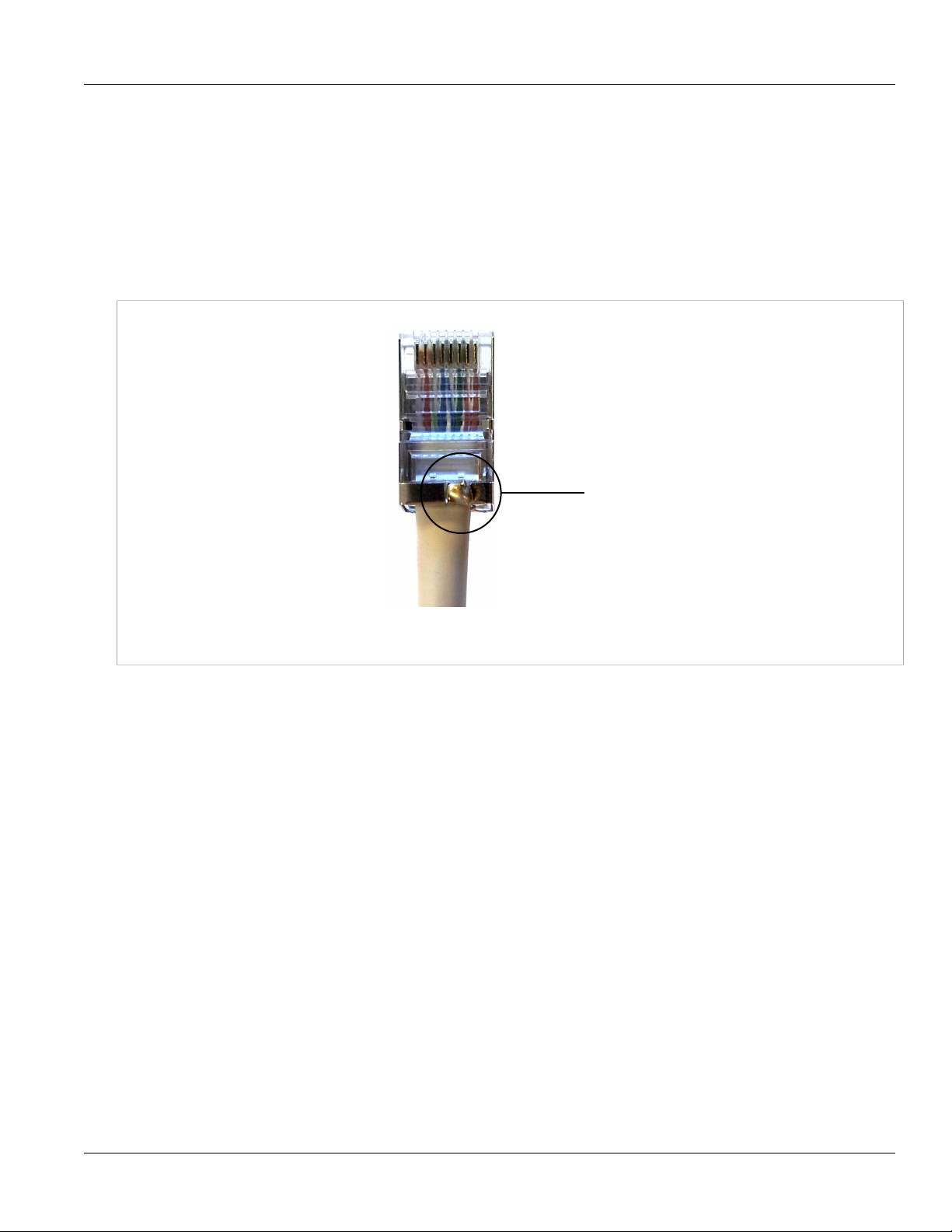
5. Refer to Figure 25.
• Loop the drain wire over the prepared grounding shield of the RJ45.
• Solder in position and trim off the remaining drain wire.
Figure 25: Solder the Drain Wire
6. Refer to Figure 26.
• Insert the modular plug into the plug housing.
• Align the latch with the LATCH slot.
• Press the modular plug into the plug housing until it bottoms out.
Installation Procedure
Chapter 4
Figure 26: Assembly of Connector Components
7. Refer to Figure 27. While maintaining inward pressure on the plug or keeping the dust cover engaged,
tighten the compression nut to 0.56Nm (5 In-lbs).
Figure 27: Connecting the Cable to the CPE
Assembling the RJ45 Connector 33
Page 42

Chapter 4
Installation Procedure
Section 4.10.3
RUGGEDCOM WiN5100/WiN5200
Installing the WiN1010 Data Adaptor
The WiN1010 data adaptor powers the ODU CPE and distributes data. The WiN1010 data adaptor unit provides
RJ-45 input connectors that include 10/100Base-T transformers for connection to an IEEE802.3 (10/100BaseT) compatible device. The unit receives power from 100V to 240V AC using an IEC-320-C14 industry standard
connector.
CAUTION!
Important:
The power supply AC cord should be 3 wires, 18 AWG minimum, with length less than 4.5 m, and
safety certified according to national rules.
A single output RJ-45 connector provides 10/100 Base-T data and power to the outdoor unit over a
Category 5e cable. This cable provides for the bi-directional transfer of data and signalling as well as a
power feed to the outdoor equipment.
NOTE
The Category 5e Ethernet cable is not included. Refer to Appendix B, IDU to ODU Cable Specifications
for detailed technical specifications.
User Guide
Figure 28: Power over Ethernet Connection Schematic
NOTE
Before connecting the WiN1010 data adaptor to the 110 VAC/220 VAC power source, verify that all
system components are properly installed. Make sure that all cable connectors are securely positioned
in the appropriate ports.
Procedure: Connecting Power to the CPE
1. Connect a Category 5e cable between the CPE and the WiN1010 data adaptor.
2. Connect a Category 5e cable between the WiN1010 data adaptor and a 10/100 Base-T port of a switch,
router, or PC.
34 Installing the WiN1010 Data Adaptor
Page 43

RUGGEDCOM WiN5100/WiN5200
User Guide
3. Connect the WiN1010 data adaptor to the 110 VAC/220 VAC power source using the cable.
Section 4.10.4
WiN1010 Data Adaptor LED Indicators
LEDs on the WiN1010 data adaptor front panel indicate the status of the WiN1010 power supply.
Table: WiN1010 Data Adaptor LED Indications
Name Color Description
PWR Green Input power is connected
LAN Green LAN link/activity display
WLNK Green Wireless link/activity display
Section 4.11
Hazardous Location Installation
Installation Procedure
Chapter 4
This equipment is suitable for use in Class 1, Division 2, Groups A, B, C, D hazardous locations when installed
using the Class 1, Division 2 installation kit (P/N MKIT0090).
WARNING!
EXPLOSION HAZARD
• Substitution of components may impair suitability for Class I, Division 2
• Do not disconnect equipment unless power has been switched off or the area is known to be nonhazardous
• Use only Lambda DPP240-48-1 Power Supply in conjunction with the unit
RISQUE D’EXPLOSION
• La substitution decomposants peut rendre ce matériel inacceptable pour les emplacements de
Classe I, Division 2
• Avant de déconnecter l’equipment, couper le courant ou s’assurer que l’emplacement est désigné
non dangereux
• Utilisez l’unité uniquement avec une batterie de la marque Lamba DPP240-48-1
Contents of the Class 1, Division 2 Installation Kit:
• Lambda power supply unit (model DPP240-48-1)
• Y-Box Surge Suppression Unit
• DC cable for connection between the power supply unit (PSU) and the power-over-ethernet (PoE) injector
To install the equipment in a hazardous location, do the following:
1. Connect a DC cable between the PSU and PoE injector.
WiN1010 Data Adaptor LED Indicators 35
Page 44

Chapter 4
Installation Procedure
Figure 29: Connection Scheme
2. Connect a Category 5e cable between the PoE injector (Data+Power jack) and the CPE.
3. Connect a Category 5e cable between the Ethernet switch and the PoE injector (Data jack).
4. Connect the AC open-ended cable to the PSU.
RUGGEDCOM WiN5100/WiN5200
User Guide
Figure 30: Complete Class 1 Division 2 Installation Kit
CAUTION!
The power supply AC cord should be 3 wires, 18 AWG minimum, with a length of less than 4.5 m, and
safety certified according to national rules.
36 Hazardous Location Installation
Page 45

RUGGEDCOM WiN5100/WiN5200
User Guide
Equipment Configuration and Monitoring
Equipment Configuration and
Monitoring
This section describes how to configure basic CPE parameters. You can preconfigure the CPE in the lab,
eliminating the need to configure the unit in the field. After installing a preconfigured unit, configure additional
parameters remotely through the wireless link.
Section 5.1
Connecting to and Logging In to the CPE
This section describes how to set up the network parameters in Microsoft Windows so you can connect a
computer to the WiN5100 or WiN5200 . For instructions on how to configure the network parameters for other
operating systems, refer to your operating system documentation.
Before beginning, ensure that the CPE is connected to the Power over Ethernet (PoE) power adaptor and that
power is applied.
Chapter 5
Procedure: Connecting a computer to the CPE
1. Ensure that the PoE adaptor is connected to the base station. Connect the computer’s Ethernet port to the
PoE adaptor’s Ethernet port.
2. On the computer, click Start and select Control Panel.
3. In the Control Panel, select Network and Internet Connections.
4. Select Network Connections and then double-click Local Area Connection. The Local Area Connections
Properties dialog appears with the General tab selected.
Figure 31: Windows Local Area Connection Properties dialog
5. In the Items list, select Internet Protocol (TCP/IP) and click the Properties button. The Internet Protocol
(TCP/IP) Properties dialog appears.
Connecting to and Logging In to the CPE 37
Page 46

Chapter 5
Equipment Configuration and Monitoring
Figure 32: Windows TCP/IP Properties dialog
RUGGEDCOM WiN5100/WiN5200
6. Assign your computer the IP address 192.168.254.250 and the subnet 255.255.255.0.
7. On the Internet Protocol (TCP/IP) Properties dialog, click OK. On the Local Area Connection Properties
dialog, click Close.
8. Launch your web browser and type https://192.168.254.251 in the address field.
User Guide
NOTE
For information on browser versions and compatibility, refer to the release notes for your software
version.
9. Press Enter. The Login window appears.
10. Enter your user name and password and click Log In. The RUGGEDCOM WiN5100/WiN5200 management
interface appears.
Figure 33: CPE General Statistics pane
38 Connecting to and Logging In to the CPE
Page 47

RUGGEDCOM WiN5100/WiN5200
User Guide
Equipment Configuration and Monitoring
NOTE
The default user name is admin and the default password is generic. The user name and
password are case sensitive.
Section 5.2
Configuring the CPE
This section describes how to configure the initial CPE settings. This section describes just the minimal setting
required to connect the CPE to the network. After installing the minimally configured CPE, configure additional
parameters remotely through the wireless link.
Procedure: Configuring the WiN5100/WiN5200
1. Connect a computer to the CPE and log in to the CPE management interface. For instructions, see
Section 5.1, “Connecting to and Logging In to the CPE”.
2. Click the WiMAX button. The Scanner Settings pane appears.
Chapter 5
Figure 34: Scanner Settings pane
3. Review the entries in the Scanner Table and ensure that the CPE is configured to work in the correct
frequency.
4.
To add an entry to the Scanner Table, click the button. A new row appears in the table. You can add up to
32 rows to the table.
Configure the bandwidth and frequency settings in the following fields:
Configuring the CPE 39
Page 48

Chapter 5
Equipment Configuration and Monitoring
Table: Scanner Table fields
Field Description
Priority Sets the scanning priority.
Bandwidth [MHz] Sets the scanning bandwidth.
Values: 3.5 MHz | 5 MHz | 7 MHz | 10 MHz
RUGGEDCOM WiN5100/WiN5200
User Guide
Start frequency
[kHz]
Step [kHz] Sets the scanning step.
End frequency [kHz] Sets the end of the scanning range.
Sets the start of the scanning range.
NOTE
The frequency and bandwidth should match the base station configuration.
5.
To remove a row from the table, select the row and click the button. The row is removed from the table.
6. After making changes to the Scanner Settings table, click the Apply button.
7. To begin transmitting, click the Connect button.
8. Click the Network button. The IP Settings pane appears.
Figure 35: IP Settings pane
9. Configure the CPE IP addresses in the following fields:
Table: IP Settings fields
Field Description
Configured LAN IP
Address
Configured LAN
Mask
40 Configuring the CPE
Sets the CPE LAN IP address. Use this address for local CPE management through a direct connection
between the CPE and a computer.
Sets the CPE LAN subnet mask.
Page 49

RUGGEDCOM WiN5100/WiN5200
User Guide
Field Description
Equipment Configuration and Monitoring
Chapter 5
RF IP Address Sets the CPE RF network IP address. Use this address for remote CPE management through the core
RF IP Subnet Mask Sets the CPE RF network subnet mask.
RF IP Default GW Sets the CPE RF network default gateway.
network.
10. Click the Apply button.
11. If you changed the Configured LAN IP Address or Configured LAN Mask fields, reboot the CPE:
a. Click the Management button. The System Functions pane appears.
b. Click the Reboot button. The CPE reboots.
12. Review the CPE statistics and ensure that the CPE is operational. Click the Statistics button. The General
Statistics pane appears.
Figure 36: General Statistics pane
13. Confirm that the CPE Status field indicates that the CPE is “Operational”.
14. Review the service flow information and ensure that the service flows are created. Click the Statistics button
and select Service Flow. The Service Flow pane appears.
Configuring the CPE 41
Page 50

Chapter 5
Equipment Configuration and Monitoring
RUGGEDCOM WiN5100/WiN5200
User Guide
Figure 37: Service Flow pane
15. Log out of the CPE management interface. Click the Management button. The System Functions pane
appears.
16. Click the Logout button. You are logged out of the CPE management interface.
42 Configuring the CPE
Page 51

RUGGEDCOM WiN5100/WiN5200
User Guide
CPE Management Interface
CPE Management Interface
This chapter describes how to use the CPE management interface. Use the CPE management interface to
configure and control CPE settings and functions. You can access the CPE management interface through the
CPE’s LAN or RF IP address.
Section 6.1
Using the CPE Management Interface
The CPE management interface consists of four main areas:
• Configuration Buttons — a set of buttons providing access to configuration options. To select a group of
configuration options, click a button.
• Options Pane — a set of links providing access to individual configuration panes. To select a specific
configuration pane, click a link.
Chapter 6
• Display Pane — displays fields and controls for configuration options and system information displays.
Using the CPE Management Interface 43
Page 52

Chapter 6
CPE Management Interface
RUGGEDCOM WiN5100/WiN5200
User Guide
Figure 38: CPE Management Interface Controls
Section 6.1.1
Configuration Buttons
The configuration buttons provide access to the main groups of configuration options. Clicking a button displays
a set of links in the Options Pane. Clicking a link in the options pane displays a pane where you can review and
configure system parameters, or review system data.
Figure 39: CPE Configuration Buttons
Table: Configuration Buttons and Options Pane Links
Configuration Button Description Option Pane Links
Network Access to CPE network settings. IP Settings
Ethernet Settings
44 Configuration Buttons
Page 53

RUGGEDCOM WiN5100/WiN5200
User Guide
Configuration Button Description Option Pane Links
Access List
CPE Management Interface
Chapter 6
WiMAX Access to WiMAX scanner, authentication,
mobility, and radio settings.
Management Access to general CPE management
settings and functions.
Statistics Displays general CPE, RF, network, and
service flow statistics.
Section 6.2
Scanner Settings
Authentication
Mobility
Radio
System Functions
Log Management
Remote Management
SW Upgrade
SNMP
Alarms & Traps
NTP Server
Developer Mode
Ethernet Lock
Radius Login
General
RF
Network
Service Flow
System Management
This section describes how to:
• manage general system functions. See Section 6.2.1, “Managing System Functions”.
• change the management interface password. See Section 6.2.2, “Changing the CPE Management Interface
Password”.
• manage CPE users and access levels. See Section 6.2.3, “Users and Access Levels”.
• configure the syslog parameters. See Section 6.2.6, “Log Management”.
• configure the remote management parameters. See Section 6.2.7, “Remote Management Parameters”.
• manage software versions and perform software upgrades. See Section 6.2.8, “Software Version
Management”.
• manage SNMP. See Section 6.2.9, “SNMP Administration”.
• manage Alarms & Traps. See Section 6.2.10, “Alarms & Traps”.
• manage the NTP Server. See Section 6.2.11, “NTP Server”.
• access Developer Mode. See Section 6.2.12, “Developer Mode”.
• lock the CPE. See Section 6.2.13, “Ethernet Lock”.
• log in from a remote location. See Section 6.2.14, “Radius Login”.
System Management 45
Page 54

Chapter 6
CPE Management Interface
Section 6.2.1
RUGGEDCOM WiN5100/WiN5200
Managing System Functions
The System Function pane displays the CPE name and provides general system controls. On this pane, you
can change the CPE password, connect to and disconnect from the base station, reboot the CPE, log out from
the management interface, and restore the CPE to its factory default settings.
Procedure: Accessing the System Functions pane
1. Click the Management button. The System Functions pane appears.
User Guide
Figure 40: System Functions pane
2. The following operations can be performed from this pane:
• Set the CPE name: The CPE name appears at the top of many of the management interface panes,
identifying the CPE unit as you work with the management interface. In the CPE name field, type a name
and click the Apply button. The CPE name appears in the at the top of the management interface panes.
• Link Watchdog: You can set the Link Watchdog function to reset the device if it is not in an operational
state for a continuous time. In the Link WatchDog field, select Disabled, Smart or Always and click the
Apply button. The default setting is Smart.
• Link Timeout (min): You can change the number of minutes before the Link Watchdog function times
out. In the Link Timeout (min) field, enter the number of minutes and click the Apply button. The default
setting is 15.
• Change the CPE password: You can change the password used to log in to the CPE management
interface. For more information, see Section 6.2.2, “Changing the CPE Management Interface Password”.
• Connect the CPE to the base station: To begin broadcasting and connect to the base station, click the
Connect button.
46 Managing System Functions
Page 55

RUGGEDCOM WiN5100/WiN5200
User Guide
CPE Management Interface
• Disconnect the CPE from the base station: To stop broadcasting and disconnect from the base station,
click the Disconnect button.
• Reboot the CPE: To reboot the CPE and run the software in the “Primary” memory bank, click the Reboot
button.
• Log out of the management interface: To log out of the CPE management interface, click the Logout
button.
• Restore the CPE to factory defaults: To restore the CPE to its factory default settings and reboot the
CPE, click the Set Factory Defaults button.
• Partially Restore the CPE to factory defaults: To restore the CPE to its factory default settings, except
for parameters that affect CPE connectivity, and reboot the CPE, click the Set Partial Defaults button.
Section 6.2.2
Changing the CPE Management Interface Password
The Change Password for User Admin pane appears when you click the Change Password button on the
System Functions pane. On this pane, you can change the the CPE management interface password for the user
admin.
Chapter 6
Procedure: Changing the Admin Password
1. Click the Management button. The System Functions pane appears.
2. Click the Change Password button. The Change Password for User Admin pane appears.
Figure 41: Change Password for User Admin pane
3. In the Current Password field, type the current password. The default password is generic.
4. In the New Password field, type the new password.
5. In the Confirm Password field, retype the new password.
6. Click the Apply button.
Changing the CPE Management Interface Password 47
Page 56

Chapter 6
CPE Management Interface
Section 6.2.3
RUGGEDCOM WiN5100/WiN5200
Users and Access Levels
Access to the CPE web management application is secured through user accounts and access levels. Two
access levels are available:
• Admin – user can access all read and write options, including user definitions.
• Guest – user can access all read options only.
Section 6.2.3.1
Adding Users
Add users and set user access levels on the Device Access Permissions pane. Only users with the Admin
access level can add and manage user accounts.
Procedure: Setting Access Permissions
1. Click the Management button. The Management options appear in the options pane.
2. In the options panel, click the Access Permissions link. The Device Access Permissions pane appears.
User Guide
Figure 42: Device Access Permissions pane
3. To add a user:
•
Click the button. A new row appears in the Permitted Users table.
• In the User Name field, type the user name.
• In the Access Level column, select an access level for the user.
• In the Password column, type the password for the user.
• In the Retype Password column, retype the password for the user.
• Click the Apply button.
4. To delete a user:
• Select a user from the Permitted Users list.
•
Click the button.
48 Users and Access Levels
Page 57

RUGGEDCOM WiN5100/WiN5200
User Guide
• Click the Apply button.
Section 6.2.4
Loading HTTPS Certificates and Private Keys
Use the Load HTTPS certificates pane to load HTTPS certificates or private keys.
NOTE
Resetting the base station to its factory defaults will erase the loaded certificate, key and delete the
password from the UV file (as the whole UV is erased). The base station will revert its default certificate
and key.
Procedure: Loading HTTPS Certificates
NOTE
• All certificates and keys must be saved in .pem format
• The filename for the certificate must be httpscert.pem
• The filename for the private key must be httpskey.pem
• The maximum certificate file size is 20 kb
• The maximum private key file size is 4 kb
• The private key password can be up to 16 characters long
CPE Management Interface
Chapter 6
1. Click the Management button. The Management options appear in the options pane.
2. In the options panel, click the HTTPS Certificate link. The Load HTTPS certificates pane appears.
Figure 43: Load HTTPS certificates pane
3. Enter a passphrase in the Private Key Passphrase box.
4. Under HTTPS Certificates, select the certificate type and then click the adjacent Choose File button.
Loading HTTPS Certificates and Private Keys 49
Page 58

Chapter 6
CPE Management Interface
5. Select the file to upload.
6. Click the Load button to load the certificate or key.
7. Click the Certificate Verify button to verify the passphrase, certificate and key.
8. Click the Apply button.
9. Reboot the base station:
a. Click the Quick Start button. The Quick Start Settings pane appears.
b. Click the Reboot button.
Section 6.2.5
Generating SSH Keys
Use the SSH Keys pane to reboot the base station and generate new SSH keys.
Procedure: SSH Keys
1. Click the Management button. The Management options appear in the options pane.
RUGGEDCOM WiN5100/WiN5200
User Guide
2. In the options panel, click the SSH Keys link. The SSH Keys pane appears.
Figure 44: SSH Keys pane
NOTE
Key generation can take up to 15 minutes to complete.
3. Click the Generate SSH Keys button. The base station reboots and generates new SSH keys.
50 Generating SSH Keys
Page 59

RUGGEDCOM WiN5100/WiN5200
User Guide
Section 6.2.6
Log Management
On the Syslog Configuration and Log Files panes, you configure the log management options.
Procedure: Setting Syslog Configuration Options
1. Click the Management button. The Management options appear in the options pane.
2. In the options panel, click the Log Management link. The Syslog pane appears.
CPE Management Interface
Chapter 6
Figure 45: Syslog pane
3. Review and set the syslog configuration parameters in the following fields:
Table: Syslog Configuration Fields
Field Description
Syslog Enable Enables or disables logging.
Values: Enable | Disable
Default: Disable
Server IP Sets the IP address of the server to which log files are uploaded. Type an IPv4 address.
Values: IPv4 address
Default: 0.0.0.0
UDP Port (1-65535) Sets the UDP port on the server to use when uploading the log files to the server. Type a value in
the range of 1 to 65535.
Values: Number in the range of 1 to 65535
Default: 514
4. Click the Apply button.
Section 6.2.7
Remote Management Parameters
On the Remote Management panes, you configure the management port, management VLAN, and DSCP
marking parameters:
Log Management 51
Page 60

Chapter 6
CPE Management Interface
RUGGEDCOM WiN5100/WiN5200
• Section 6.2.7.1, “Configuring the Management Port”
• Section 6.2.7.2, “Configuring the Management VLAN”
• Section 6.2.7.3, “Configuring DSCP Marking”
Section 6.2.7.1
Configuring the Management Port
On the Management Port pane, you configure the CPE management port. Note that changing the management
port affects both local and remote management access.
Procedure: Setting the Management Port
1. Click the Management button. The System Functions pane appears.
2. In the options pane, click the Remote Management link. The Management Settings pane appears.
User Guide
Figure 46: Management Settings pane
3. In the Management port [1-65535] field, type the port number you want to use for the management port.
The default port is 80.
4. Click the Apply button.
5. After changing the Management port [1-65535] field, reboot the CPE:
a. Click the Management button. The System Functions pane appears.
b. Click the Reboot button. The CPE reboots.
Section 6.2.7.2
Configuring the Management VLAN
On the Management VLAN pane, you configure the management VLAN options. The options include the VLAN
number and the 802.1p priority value. Outgoing management frames are tagged with the configured VLAN
number and priority. Incoming management frames must be tagged with the same values, or the CPE drops the
incoming frames.
Procedure: Setting Management VLAN Configuration Options
1. Click the Management button. The System Functions pane appears.
2. In the options panel, click the Remote Management link, and then click the Management VLAN link. The
Management VLAN pane appears.
52 Configuring the Management Port
Page 61

RUGGEDCOM WiN5100/WiN5200
User Guide
Figure 47: Management VLAN pane
3. Review and set the management VLAN parameters in the following fields:
Table: Management VLAN Fields
Field Description
CPE Management Interface
Chapter 6
VLAN Number Displays an identifier for the management VLAN. When setting this value, ensure that
802.1p bits [0-7] Sets the 802.1p priority value for the management VLAN. Type a value from 0 to 7.
the relevant VLAN service is created on the base station and that remote management
is enabled.
Values: Any numeric value
Default: 0
Values: A number in the range of 0 to 7
Default: 6
4. Click the Apply button.
Section 6.2.7.3
Configuring DSCP Marking
On the DSCP Marking pane, you configure the Differentiated Services Code Point marking value. DSCP marking
identified outgoing management traffic only.
Procedure: Setting the DSCP Marking Parameter
1. Click the Management button. The System Functions pane appears.
2. In the options panel, click the Remote Management link, and then click the DSCP Marking link. The DSCP
Marking pane appears.
Configuring DSCP Marking 53
Page 62

Chapter 6
CPE Management Interface
Figure 48: DSCP Marking pane
3. In the DSCP marking [0-63] field, type a value in the range of 0 to 63. The default value is 48.
4. Click the Apply button.
Section 6.2.8
RUGGEDCOM WiN5100/WiN5200
User Guide
Software Version Management
Permanent memory storage is organized in two memory banks, “1” and “2”. Two versions of the operating system
software can be stored on the CPE, one in each memory bank. Each memory bank is designated as either
the “Primary” or “Secondary” memory bank. When you reset or reboot the CPE, it always runs the software
installed in the “Primary” bank. The CPE web console provides controls to change the “Primary” and “Secondary”
designations on the memory banks, and to reboot the CPE using the “Secondary” memory bank for testing.
Software saved in one bank can be copied to the other, allowing you to create backups and to restore or update
versions as required.
This section describes how to manage CPE software versions 4.2 and later, including how to upload and
download files, manage the memory banks and their “Primary” and “Secondary” designations, and how to backup
and restore the operating system.
Section 6.2.8.1
Upgrading CPE Software
For safety and reliability, the CPE software upgrade process consists of the following steps, with checks and
verification at several stages:
1. Load the new software image to the secondary memory bank:
• Configure the FTP server from which the new software files will be downloaded (see Section 6.2.8.3,
“Downloading CPE Software”):
• Download the software update files to the secondary memory bank (see Section 6.2.8.3, “Downloading
CPE Software”).
• Verify that the downloaded software files have been correctly saved to the secondary memory bank (see
Section 6.2.8.5, “Managing the Secondary Memory Bank”).
2. Perform a trial run of the new software image:
On the SW Properties pane, click Run Secondary.
54 Software Version Management
Page 63

RUGGEDCOM WiN5100/WiN5200
User Guide
CPE Management Interface
The CPE will reset and load the software image in the secondary memory bank. This process will take
approximately two minutes.
3. Commit the new software image as the new default software:
Again on the SW Properties pane, click Set As Primary in order to set the current memory bank (currently
denoted Secondary) as Primary. Doing so will cause the software in the memory bank newly designated
Primary to be run by default on bootup.
Section 6.2.8.2
Viewing Software Properties
The SW Properties pane displays information about the software loaded into each CPE memory bank. On this
pane, you can reboot the CPE from the secondary bank, set the current bank as the primary bank, and reboot the
CPE.
Procedure: Viewing software properties
1. Click the Management button. The System Functions pane appears.
2. In the options pane, click the SW Upgrade link. The SW Properties pane appears.
Chapter 6
Figure 49: SW Properties pane
3. The SW Properties pane displays the following information:
Table: SW Properties
Field Description
Current Active Bank Displays the name of the memory bank from which the CPE software is running.
Viewing Software Properties 55
Page 64

Chapter 6
CPE Management Interface
Field Description
Current SW Location Displays the number of the memory bank from which the CPE software is running.
Primary SW Version Displays the version number of the software in the Primary memory bank.
Primary SW Location Displays the number of the current Primary memory bank.
RUGGEDCOM WiN5100/WiN5200
User Guide
Values: Primary | Secondary
Values: 1 | 2
Values: 1 | 2
Primary CDC Displays the filename of the CDC (Customer Defaults Configuration) file in the Primary
Primary UV Displays the filename of the UV (Unique Value) file in the Primary memory bank.
Secondary SW Version Displays the version number of the software in the Secondary memory bank.
Secondary SW Location Displays the number of the memory bank selected as the Secondary memory bank.
Secondary CDC Displays the filename of the CDC (Customer Defaults Configuration) file in the
Secondary UV Displays the filename of the UV (Unique Value) configuration file in the Primary memory
Configuration Changes Counter Displays the number of changes made to configuration values on the CPE. This value
memory bank.
Secondary memory bank.
bank.
only includes changes to configuration values. It does not include events, such as
setting the primary software image or uploading a file.
4. The following operations can be performed from this pane:
• Run Secondary — Reboot the CPE and run the “Secondary” software image. Reboot a second time to
run the CPE using the “Primary” software image.
• Set as Primary — Set the current running software as the “Primary” image. For example, if the CPE is
running from the “Secondary” image, the “Primary” and “Secondary” designations are exchanged.
• Reboot — Reboot the CPE and run the “Primary” image.
Section 6.2.8.3
Downloading CPE Software
Use the SW Download pane to download CPE software from your FTP server. The CPE downloads all software
to the “Secondary” memory bank.
Procedure: Downloading software
1. Click the Management button. The Current Status pane appears.
2. In the options pane, click the SW Upgrade link, and then click the SW Download link. The SW Download
pane appears.
56 Downloading CPE Software
Page 65

RUGGEDCOM WiN5100/WiN5200
User Guide
Figure 50: SW Download pane
3. Set the download parameters in the following fields:
Table: Download Parameters
CPE Management Interface
Chapter 6
Field Description
FTP Server IP Type the IPv4 address for the FTP server from which the CPE software is to be
Directory Type the directory path to the CPE software on the FTP server.
File Type Select the type of file to download:
File Name Type the name of the file you want to download.
User Name Type the user name used to log in to the FTP server.
Password Type the password used to log in to the FTP server.
downloaded.
• Package — The software package file provided with an upgrade package. For
example: ruggedupgrade.ini
• Web Resource — A web console template file. For example: web.rc
• CDC — A Common Default Configuration file. For example: BS-Val-Cdc.xml
• UV — A Unique Value file. For example: BS-Val-Unique.xml
4. Click the Download button. The CPE downloads the specified file from the FTP server directory to the
“Secondary” memory bank.
Section 6.2.8.4
Managing the Primary Memory Bank
Use the Primary Components pane to manage software in the “Primary” memory bank. On this pane, you can
view information for the files in the memory bank, upload files from the memory bank to your FTP server, and
copy files from the “Primary” memory bank to the “Secondary” memory bank.
Before uploading files to an FTP server, you must configure an FTP server on the SW Download pane. For
instructions on how to configure the FTP server properties, see Section 6.2.8.3, “Downloading CPE Software”.
Managing the Primary Memory Bank 57
Page 66

Chapter 6
CPE Management Interface
Procedure: Viewing files in the Primary memory bank
RUGGEDCOM WiN5100/WiN5200
1. Click the Management button. The Current Status pane appears.
2. In the options pane, click the SW Upgrade link, and then click the Primary Bank link. The Primary
Components pane appears.
User Guide
Figure 51: Primary Bank Components pane
3. The Primary Components Table displays the following information:
Table: Primary Components Table
Field Description
Name Displays the software component filename.
Type Displays the software component file type.
Values: Package | Application | VxWorks | Blob | Script | WebResource | Defaults | CDC
| Regulation | UV | GUI
Version Displays the software component version number.
4. To upload a file to your FTP server:
NOTE
Before uploading files to an FTP server, you must configure an FTP server on the FTP
Server Properties pane. For instructions on how to configure the FTP server properties, see
Section 6.2.8.3, “Downloading CPE Software”.
• Select a file from the Primary Components Table.
• Click the Upload File.
5. To copy a file to the “Secondary” memory bank:
58 Managing the Primary Memory Bank
Page 67

RUGGEDCOM WiN5100/WiN5200
User Guide
CPE Management Interface
NOTE
Before copying the file, ensure that it does not already exist in the “Secondary” memory bank. If
the file is present in the “Secondary” memory bank, delete the file from the “Secondary” memory
bank before copying. For instructions on how to delete files from the “Secondary” memory bank,
see Section 6.2.8.5, “Managing the Secondary Memory Bank”.
• Select a file from the Primary Components Table.
• Click the Copy File.
6. To copy all files to the “Secondary” memory bank:
• Click the Copy directory.
Section 6.2.8.5
Managing the Secondary Memory Bank
Use the Secondary Components pane to manage software in the “Secondary” memory bank. On this pane, you
can view information for the files in the memory bank, upload files from the memory bank to your FTP server, and
delete files from the memory bank.
Before uploading files to an FTP server, you must configure an FTP server on the FTP Server Properties
pane. For instructions on how to configure the FTP server properties, see Section 6.2.8.3, “Downloading CPE
Software”.
Chapter 6
Procedure: Viewing files in the Secondary memory bank
1. Click the Management button. The Current Status pane appears.
2. In the options pane, click the SW Upgrade link, and then click the Secondary Bank link. The Secondary
Components pane appears.
Managing the Secondary Memory Bank 59
Page 68

Chapter 6
CPE Management Interface
RUGGEDCOM WiN5100/WiN5200
User Guide
Figure 52: Secondary Bank Components pane
3. The Secondary Components Table displays the following information:
Table: Secondary Components Table
Field Description
Name Displays the software component filename.
Type Displays the software component file type.
Values: Package | Application | VxWorks | Blob | Script | WebResource | Defaults | CDC
| Regulation | UV | GUI
Version Displays the software component version number.
4. To upload a file to your FTP server:
NOTE
Before uploading files to an FTP server, you must configure an FTP server on the FTP
Server Properties pane. For instructions on how to configure the FTP server properties, see
Section 6.2.8.3, “Downloading CPE Software”.
• Select a file from the Secondary Components Table.
• Click the Upload File.
5. To delete a file:
• Select a file from the Secondary Components Table.
• Click the Delete File.
6. To delete all files:
60 Managing the Secondary Memory Bank
Page 69

RUGGEDCOM WiN5100/WiN5200
User Guide
CPE Management Interface
• Click the Delete Directory.
Section 6.2.8.6
File Status
Use the File Transfer Status pane to view the status of upload and download operations between the CPE and
your FTP server. You can also cancel current upload and download operations from this pane.
Procedure: Viewing File Transfer Status
1. Click the Management button. The Current Status pane appears.
2. In the options pane, click the SW Upgrade link, and then click the Files Status link. The File Transfer
Status pane appears.
Chapter 6
Figure 53: File Transfer Status pane
3. From the File Operation Status list, select an operation status:
• OK — displays successfully completed file transfers.
• Not Started — displays requested file transfers that have not yet started.
• In Process — displays file transfers that are currently in progress.
• Failure — displays failed file transfers.
4. The File Transfer Operation Status table displays the following information for the files in the selected
operation status:
Table: File Transfer Operation Status table
Field Description
Index Displays a unique identifier for the file.
Operation Displays the file transfer operation performed on the file.
Values: Download | Upload | Delete | Copy | Operations (indicates the completion of a
batch operation on several files)
File Name Displays the filename for the uploaded or downloaded file.
Status Displays the status of the file transfer operation.
File Status 61
Page 70

Chapter 6
CPE Management Interface
Field Description
Values: OK | Not Started | In Process | Failure
RUGGEDCOM WiN5100/WiN5200
5. To cancel a download or upload operation that is currently in progress:
• Click the Cancel button.
Section 6.2.9
SNMP Administration
In SNMP administration, you enable and disable SNMPv2 and SNMPv3, configure trap destinations, SNMP
communities, and MIB2 system identification parameters.
For instructions on enabling and disabling SNMPv2 and SNMPv3, and on setting SNMP trap destinations, see
Section 6.2.9.1, “SNMP General Settings”.
For instructions on configuring SNMPv2, see Section 6.2.9.2, “SNMPv2 Configuration”.
For instructions on configuring SNMPv3, see Section 6.2.9.3, “SNMPv3 Configuration”.
For instructions on setting the MIB2 system identification information, see Section 6.2.9.5, “MIB2 System”.
User Guide
Section 6.2.9.1
SNMP General Settings
On the SNMP General Settings pane, you can enable or disable SNMPv2 and SNMPv3, set the SNMP trap
destinations, and access the SNMPv2 and SNMPv3 configuration settings. You can specify up to five trap
destination addresses.
Procedure: Setting the SNMP general settings
1. Click the Admin button. The Admin options appear in the options pane.
2. In the options pane, click the SNMP link, and then click the SNMP General Settings link. The SNMP
General Settings pane appears.
62 SNMP Administration
Page 71

RUGGEDCOM WiN5100/WiN5200
User Guide
CPE Management Interface
Chapter 6
Figure 54: SNMP General Settings
3. In the SNMPv2c and SNMPv3 fields, enable or disable SNMPv2c and SNMPv3.
4. In the Managers Table, add up to five trap destination addresses:
a.
Click the button. A new row appears in the Managers Table.
b. Type an IP address in the new row.
5.
To remove an SNMP trap destination, select a row and click the button. If no rows are selected, clicking the
button removes the last entry in the table.
6. Click the Apply button.
7. To configure SNMPv2 parameters, click the SNMPv2 Configuration button. See Section 6.2.9.2, “SNMPv2
Configuration”.
8. To configure SNMPv3 parameters, click the SMPv3 Configuration button. See Section 6.2.9.3, “SNMPv3
Configuration”.
Section 6.2.9.2
SNMPv2 Configuration
The SNMPv2c Configuration pane appears when you click the SNMPv2 Configuration button on the SNMP
General Settings pane. On this pane, you set the SNMPv2c read, write, and trap community settings.
Procedure: Setting the SNMPv2c parameters
1. On the SNMP General Settings pane, click the SNMPv2 Configuration button. The SNMPv2c
Configuration pane appears.
SNMPv2 Configuration 63
Page 72

Chapter 6
RUGGEDCOM WiN5100/WiN5200
CPE Management Interface
Figure 55: SNMPv2c Configuration pane
2. The Current SNMPv2 Status field displays the current status for the SNMPv2 system: Enabled or Disabled.
3. Review and set the SNMPv2c settings in the following fields:
User Guide
Table: SNMPv2c Configuration table
Field Description
SNMP Read Community The SNMP community name for read access. This name can be used as a password
SNMP Write Community The SNMP community name for write access. This name can be used as a password
SNMP Trap Community The SNMP community name to use when the SNMP service receives a request that
for secure information retrieval. Type a name in the field. The SNMP Read Community
name must be different from the SNMP Write Community name.
Default: public
for secure set commands. Type a name in the field. The SNMP Write Community name
must be different from the SNMP Read Community name.
Default: private
does not contain the correct community name and does not match an accepted host
name.
Default: public
4. Click the Apply button.
Section 6.2.9.3
SNMPv3 Configuration
The SNMPv3 Configuration pane appears when you click the SMPv3 Configuration button on the SNMP
General Settings pane. On this pane, you configure SNMPv3 users, authentication parameters, and access
groups.
Procedure: Setting the SNMPv3 parameters
1. On the SNMP General Settings pane, click the SNMPv3 Configuration button. The SNMPv3
Configuration pane appears.
64 SNMPv3 Configuration
Page 73

RUGGEDCOM WiN5100/WiN5200
User Guide
CPE Management Interface
Chapter 6
Figure 56: SNMPv3 Configuration pane
2. The Current SNMPv3 Status field displays the current status for the SNMPv3 system: Enabled or Disabled.
3. Review and set the SNMPv3 users in the Users table.
To add an SNMPv3 user, click the button. A new row appears in the Users Table. Enter the following
parameters:
Table: SNMPv3 Users Table
Field Description
Username The user name.
Authentication Passphrase The passphrase used for authentication.
Authentication Protocol Select the authentication protocol for the user.
Value: HMAC-SHA1
Privacy Passphrase The passphrase used for privacy.
Privacy Protocol Select the privacy protocol.
Value: CBC-DES
Access Group Associated the user with an SNMPv3 Access Group.
4.
To remove an SNMPv3 user, select a row in the Users Table and click the button. If no rows are selected,
clicking the button removes the last entry in the table.
5. Click the Apply button.
6. To view the SNMPv3 access groups, click the Access Groups button. See Section 6.2.9.4, “Viewing
SNMPv3 Access Groups”.
SNMPv3 Configuration 65
Page 74

Chapter 6
CPE Management Interface
Section 6.2.9.4
RUGGEDCOM WiN5100/WiN5200
Viewing SNMPv3 Access Groups
The SNMPv3 Access Groups Configuration pane appears when you click the Access Groups button on the
SNMPv3 Configuration pane. On this pane, you can review the default SNMP v3 access groups.
Procedure: Viewing the SNMPv3 Access Groups
1. On the SNMPv3 Configuration pane, click the Access Groups button. The SNMPv3 Access Groups
Configuration pane appears.
User Guide
Figure 57: SNMPv3 Access Groups Configuration
2. Review the SNMPv3 access groups in the Access Groups table:
Table: SNMPv3 Access Groups table
Field Description
Group Name The access group name.
Read View The read view for the access group.
Write View The write view for the access group.
Notification View The notification view for the access group.
Section 6.2.9.5
MIB2 System
The SNMP MIB2 settings provide subscriber station system identification information.
On the SNMP - MIB2 Settings pane, you set the subscriber station contact details, name, and street address.
This pane also displays the read-only SNMP system description, object identifier, system up time, and system
services values.
Procedure: Setting SNMP MIB2 system identification information
1. Click the Admin button. The Admin options appear in the options pane.
2. In the options panel, click the SNMP link, and then click the MIB2 System link. The SNMP - MIB2 Settings
pane appears.
66 Viewing SNMPv3 Access Groups
Page 75

RUGGEDCOM WiN5100/WiN5200
User Guide
Figure 58: SNMP MIB2 Settings pane
3. Review and set the SNMP system identification information in the following fields:
CPE Management Interface
Chapter 6
Table: MIB2 System Table
Field Description
sysDescr Displays the SNMP MIB version.
sysObjectID Displays the RUGGEDCOM private enterprise number and object identifier for the
sysUpTime Displays the length of time, in hundredths of a second, since the SNMP subsystem was
Contact Details Contains subscriber station contact information. Type a name and contact details, such
Subscriber Station Name Contains the subscriber station name. Type a descriptive name in this field.
Street Address Contains the subscriber station street address or location. Type and address or location
sysServices Displays a value indicating the set of services provided by the system. The value 2
4. Click the Apply button.
Section 6.2.10
Default: This MIB version: BS-E-12-MIB.mib
subscriber station SNMP subsystem.
Default: .1.3.6.1.4.1.15004.2.7.1
last initialized.
as an e-mail address, in this field.
in this field.
indicates the datalink/subnetwork layer.
Alarms & Traps
Use the System Alarms and SNMP Trap Settings panes to view system alarms and to configure SNMP traps.
Alarms & Traps 67
Page 76

Chapter 6
RUGGEDCOM WiN5100/WiN5200
CPE Management Interface
System Alarms
The System Alarms pane displays current system alarms. This pane is read-only; there are no parameters to set
on this pane.
Procedure: Viewing System Alarms
1. Click the Management button. The Management options appear in the options pane.
2. In the options panel, click the Alarms and Traps link. The System Alarms pane appears.
User Guide
Figure 59: System Alarms pane
3. Review the current number of alarms in the following fields:
Table: System Alarms
Field Description
Number of Critical Alarms Displays the number of critical alarms.
Number of Major Alarms Displays the number of major alarms.
Number of Warning Alarms Displays the number of warning or advisory alarms.
4. Review the current alarm settings in the Alarms Table:
Table: Alarms Table
Column Description
ID Displays the alarm type identification number.
Name Displays the alarm type. For a list of alarm and trap conditions, see the section called
Status Indicates if the alarm type is enabled or disabled.
68 Alarms & Traps
“SNMP Traps List”.
Page 77

RUGGEDCOM WiN5100/WiN5200
User Guide
Column Description
Values: Off | On
Severity Displays the severity of the alarm.
Values: Clear | Critical | Major | Warning
Category Displays the category for the alarm type.
Values: Restart | Communication | RF | Hardware | Security | Environmental |
Redundancy | Services | Link Status
Last Description Displays a message describing the alarm.
Last Update Time Displays the date and time of the most recent alarm.
CPE Management Interface
SNMP Trap Settings
On the SNMP Trap Settings panel, configure the subscriber station SNMP traps. From this pane, you can also
select traps and send them on demand.
NOTE
To send traps, you must have SNMP Trap Destinations configured. For instructions on configuring
SNMP Trap Destinations, see Section 6.2.9, “SNMP Administration”
Chapter 6
Procedure: Setting SNMP traps
1. Click the Management button. The Management options appear in the options pane.
2. In the options panel, click the Alarms and Traps link, and then click the Traps link. The SNMP Trap
Settings pane appears.
Figure 60: SNMP Trap Settings
3. In the Traps Table, review and configure the SNMP traps:
Alarms & Traps 69
Page 78

Chapter 6
CPE Management Interface
Table: Traps Table
Column Description
Trap ID Displays the trap identification number.
Trap Name Displays the trap name.
RUGGEDCOM WiN5100/WiN5200
User Guide
Activation Mode Indicates if the trap is enabled or disabled. To enable a trap, select True. To disable a
Severity Displays the severity of the trap condition.
Category Displays the category of the trap condition.
Description Displays a description of the trap condition.
Value Displays the value reported by the SNMP trap.
trap, select False.
Values: True | False
Values: Clear | Critical | Major | Warning
Values: Restart | Communication | RF | Hardware | Security | Environmental |
Redundancy | Services | Link Status
4. Click the Apply button.
For testing purposes, you can send selected traps on demand. To send traps, you must have SNMP Trap
Destinations configured. For instructions on configuring SNMP Trap Destinations, see Section 6.2.9, “SNMP
Administration”.
Procedure: Sending SNMP traps on demand
1. In the Traps Table, select one or more SNMP traps.
2. Click the Send Trap button.
SNMP Traps List
NOTE
The WIMAX-SS-TRAPS.mib file in the software release folder contains a full list of traps.
Table: SNMP Traps List
Event Name Description
RestartOK The subscriber station restarted successfully.
RestartFailure
WebLoginOK Web interface login was successful.
WebLogout Web interface logout.
WebLoginFailed Web login has failed for 10 consecutive attempts.
EthernetUp Ethernet link is up.
EthernetDown Ethernet link is down.
FileOperationsOK File operations are successful.
FileOperationsFail File operations failed.
ConfigChanged Configuration was changed successfully.
The subscriber station failed to restart. This
event reports all causes of initialization errors.
70 Alarms & Traps
Page 79

RUGGEDCOM WiN5100/WiN5200
User Guide
CPE Management Interface
Chapter 6
Event Name Description
DuplicateNsiIp Duplicate LAN IP address.
DuplicateRfiIp Duplicate RF IP address.
CPELocked
CPEUnlocked The CPE Ethernet port is unlocked to forward user data.
ACLPacketDrop
The CPE Ethernet port is locked to forward user data.
Only management data is permitted from the LAN.
If the maximum permitted number of access list
entries is exceeded, packets from any new host will
be dropped. In addition to a trap being sent at the
occurence, the trap will be sent every 1000 packets.
Section 6.2.11
NTP Server
Use the NTP Server pane to access the NTP server.
NOTE
Prior to enabling the NTP server, the Time Advertisement Enabled field must be set, on the GPS
pane in the base station. This field enables the NTP Server to work properly.
Procedure: Accessing the NTP Server
1. Click the Management button. The Management options appear in the options pane.
2. In the options panel, click the NTP Server link. The NTP Server pane appears.
Figure 61: NTP Server pane
3. Review and set the parameters in the following fields:
Table: NTP Server table
Field Description
Enable Ntp Server To set the NTP Server, select a value from this list.
Values: True | False
NTP Server 71
Page 80

Chapter 6
CPE Management Interface
Field Description
RUGGEDCOM WiN5100/WiN5200
User Guide
Local Time Displays the local time advertised by the base station. The time appears automatically in this field, if set
in the base station.
4. Click the Apply button.
Section 6.2.12
Developer Mode
Use the Developer Mode pane to access Developer Mode.
Procedure: Accessing Developer Mode
1. Click the Management button. The Management options appear in the options pane.
2. In the options panel, click the Developer Mode link. The Developer Mode pane appears.
Figure 62: Developer Mode pane
3. In the Password field, type the password for Developer Mode. To obtain this password, contact Technical
Support.
The status of the password appears in the Status field. If the password is correct, the message "Correct
Password" appears in this field.
4. Click the Apply button.
Section 6.2.13
Ethernet Lock
If enabled, the Ethernet Lock function locks ethernet ports during certain events. The CPE will be automatically
locked during the following conditions:
• When Ethernet is down.
• During system start-up, with the following exceptions:
▪ A software exception – if the reason for the system reboot was a software exception, the CPE will not be
locked.
72 Developer Mode
Page 81

RUGGEDCOM WiN5100/WiN5200
User Guide
▪ A reboot due to a watchdog reboot.
▪ The Reboot button was pressed.
▪ The CPE rebooted from the base station.
NOTE
Management traffic to/from the CPE will always pass through.
Use the Ethernet Lock pane to lock the CPE.
Procedure: Setting the Ethernet Lock parameters
1. Click the Management button. The Management options appear in the options pane.
2. In the options pane, click the Ethernet Lock link. The Ethernet Lock pane appears.
CPE Management Interface
Chapter 6
Figure 63: Ethernet Lock pane
3. Review and set the Ethernet Lock settings in the following fields:
Table: Ethernet Lock table
Field Description
Ethernet Lock Displays the setting for the Ethernet Lock.
Values: Enable | Disable
Data Forwarding Displays the setting for Data Forwarding.
Values: Allowed | Blocked
4. Click the Apply button.
Section 6.2.14
Radius Login
Use the Radius Login pane to set radius login authentication settings for remote login.
Procedure: Setting the Radius Login parameters
1. Click the Management button. The Management options appear in the options pane.
Radius Login 73
Page 82

Chapter 6
CPE Management Interface
2. In the options panel, click the Radius Login link. The Radius Login Settings pane appears.
Figure 64: Radius Login Settings pane
3. Review and set the parameters in the following fields:
RUGGEDCOM WiN5100/WiN5200
User Guide
Table: Radius Login
Field Description
Radius Login To set the Radius Login authentication mode, select a value from this list.
Values: Enable | Disable
Login AAA IP Address The configured Web Login AAA Server IP Address. Type an IP address in this field.
Login AAA Port The configured Web Login AAA Server Port. Type a value in this field.
Login AAA Secret The configured Web Login AAA Server Secret. Type a value in this field.
NAS ID The Radius NAS Identifier. Type a value in this field.
4. Click the Apply button.
Section 6.3
CPE Network Configuration
This section describes how to:
• set the CPE LAN and RF IP settings. See Section 6.3.1, “ Network IP Settings ”.
• set the CPE Ethernet settings. See Section 6.3.2, “Ethernet Settings”.
• set the Access List settings. See Section 6.3.3, “Configuring the Access List”.
Section 6.3.1
Network IP Settings
On the the IP Settings pane, configure the CPE’s LAN and RF IP addresses.
74 CPE Network Configuration
Page 83

RUGGEDCOM WiN5100/WiN5200
User Guide
CPE Management Interface
• Use the LAN IP address when you access the CPE through a direct connection to its physical Ethernet port.
• Use the RF IP address when you access the CPE through the RF network.
Procedure: Configuring the IP Settings
1. Click the Network button. The IP Settings pane appears.
Chapter 6
Figure 65: IP Settings pane
2. View and configure the LAN and RF IP settings in the following fields:
Table: IP Settings fields
Field Description
Current LAN IP Address Displays the currently configured CPE LAN IP address.
Configured LAN IP Address To change the LAN IP address, type an IPv4 address in this field. After changing this
Current LAN Mask Displays the currently configured LAN netmask.
Configured LAN Mask To change the LAN mask, type a dotted-decimal mask in this field. After changing this
RF IP mode Displays the RF IP mode: Static or DHCP. To change the mode, select a value from the
RF IP Address Displays the RF IP address. To change the address, type an IPv4 address in this field.
RF IP Subnet Mask Displays the RF IP subnet mask. To change the subnet mask, type a dotted-decimal
RF IP Default Gateway Displays the RF default gateway. To change the gateway, type an IPv4 address in this
field, you must reboot the CPE.
field, you must reboot the CPE.
list.
mask in this field.
field.
3. Click the Apply button.
4. If you changed the value in the Configured LAN IP Address or Configured LAN Mask fields, reboot the
base station:
a. Click the Management button. The System Functions pane appears.
b. Click the Reboot button. The CPE reboots.
Network IP Settings 75
Page 84

Chapter 6
CPE Management Interface
Section 6.3.2
RUGGEDCOM WiN5100/WiN5200
Ethernet Settings
On the Ethernet Settings panes, you configure VLAN tagging, the MAC address table, and MTU parameters:
• Section 6.3.2.1, “Configuring VLAN Tagging”
• Section 6.3.2.2, “Configuring the MAC Address Table”
• Section 6.3.2.3, “MTU Configuration”
Section 6.3.2.1
Configuring VLAN Tagging
On the VLAN Tagging pane, you configure the management VLAN options. The options include the VLAN
number and the 802.1p priority value. Outgoing management frames are tagged with the configured VLAN
number and priority. Incoming management frames must be tagged with the same values, or the CPE drops the
incoming frames.
Procedure: Setting the VLAN Tagging Parameters
1. Click the Network button. The IP Settings pane appears.
2. In the options panel, click the Ethernet Settings link. The VLAN Tagging pane appears.
User Guide
Figure 66: VLAN Tagging pane
3. View and configure the LAN and RF IP settings in the following fields:
Table: IP Settings fields
Field Description
VLAN ID [1-4094] Displays an identifier for the management VLAN.
Values: A number in the range of 1 to 4094.
Default: 0
802.1p bits [0-7] Sets the 802.1p priority value for the management VLAN. Type a value from 0 to 7.
Values: A number in the range of 0 to 7
Default: 0
4. Click the Apply button.
76 Ethernet Settings
Page 85

RUGGEDCOM WiN5100/WiN5200
User Guide
CPE Management Interface
5. If you changed the value in the Configured LAN IP Address or Configured LAN Mask fields, reboot the
base station:
a. Click the Management button. The System Functions pane appears.
b. Click the Reboot button. The CPE reboots.
Section 6.3.2.2
Configuring the MAC Address Table
The MAC Address Table displays the MAC addresses learned by the CPE. On the MAC Address Table pane,
you can set the MAC address aging time and clear the MAC Address Table.
Procedure: Managing the the MAC Address Table
1. Click the Network button. The IP Settings pane appears.
2. In the options panel, click the Ethernet Settings link, and then click the MAC Address Table link. The MAC
Address Table pane appears.
Chapter 6
Figure 67: MAC Address Table pane
3. In the Aging time [300-1800] sec field, set the MAC address aging time. This is the time until table entries
are removed from the MAC address table. Type a value in the range of 300 to 1800 seconds.
4. The MAC Address Table displays the following information:
Table: IP Settings fields
Field Description
Index Displays a unique identifier for the table entry.
Configuring the MAC Address Table 77
Page 86

Chapter 6
CPE Management Interface
Field Description
MAC Address Displays the MAC address of a local or remote node.
VLAN ID Displays the identifier for the Virtual LAN on which the node is active.
Aging Time [sec] Displays the time, in seconds, until the entry will be removed from the table.
Interface Displays the interface from which the CPE learned the MAC address.
Possible values include:
• Network — the base station acquired the address from the Ethernet network interface
• RF — the base station acquired the address from the RF interface
• Local — indicates the MAC address of the base station itself
RUGGEDCOM WiN5100/WiN5200
5. To remove an entry from the MAC address table, select a row in the table and click the Clear button.
6. After changing the Aging time [300-1800] sec field, click the Apply button.
Section 6.3.2.3
MTU Configuration
On the MTU pane, you can enable or disable the maximum transmission unit. The MTU specifies the size of the
largest data unit, in bytes, that the Base Station will transmit. The MTU value includes the L2 header and cyclic
redundancy check (CRC).
User Guide
Procedure: Enabling/Disabling MTU
1. Click the Backbone button. The Backbone links appear in the options pane.
2. In the options pane, click the MTU link. The MTU Configuration pane appears.
Figure 68: MTU Configuration pane
3. Under Mini-jumbo frames support, select either Enable or Disable.
4. Click the Apply button.
5. Reboot the base station:
78 MTU Configuration
Page 87

RUGGEDCOM WiN5100/WiN5200
User Guide
a. Click the Quick Start button. The Quick Start Settings pane appears.
b. Click the Reboot button.
Section 6.3.3
Configuring the Access List
If the Access List function is enabled, only MAC Addresses in this list will be able to pass data.
Procedure: Setting the Access List parameters
1. Click the Network button. The Network options appear in the options pane.
2. In the options pane, click the Access List link. The Access List pane appears.
CPE Management Interface
Chapter 6
Figure 69: Access List pane
3. Review and set the Access List settings in the following fields:
Table: Access List Configuration table
Field Description
Access List Displays the setting for the Access List.
Values: Enable | Disable
Total Number of Entries Type a number in the field.
Max Number of Self-Learned Entries Displays the maximum number of Self-Learned Entries
Default = 1
4. Review and set the Access List settings in the following fields:
Table: Access List table
Field Description
MAC Address Displays the MAC Address.
Configuring the Access List 79
Page 88

Chapter 6
CPE Management Interface
Field Description
RUGGEDCOM WiN5100/WiN5200
User Guide
Status Displays the Status. Sticky addresses remain in the table after a reboot. Non-Sticky
Type Displays Self-Learned Entries.
addresses are cleared from the table after a reboot.
Values: Sticky | Non-Sticky
Values: Self-Learned | Preprovisioned
5. In the Access List Table, you can add preprovisioned entries to the list. Self-learned entries appear in the
list automatically.
a.
Click the button. A new row appears in the Access List Table.
b. Type an IP address in the new row.
6.
To remove a MAC Address, select a row and click the button. If no rows are selected, clicking the button
removes the last entry in the table.
7. Click the Apply button.
Section 6.4
CPE Statistics
This section describes how to:
• view general CPE system statistics. See Section 6.4.1, “General Statistics”.
• view CPE hardware information. See Section 6.4.2, “Device Info”.
• view and clear CPE RF statistics. See Section 6.4.3, “RF Statistics”.
• view and clear network statistics. See Section 6.4.4, “Network Statistics”.
• view and clear service flow statistics. See Section 6.4.5, “Service Flow Statistics”.
Section 6.4.1
General Statistics
On the the General Statistics pane, you can review general CPE status and information. The General Statistics
pane is read-only; there are no parameters to set on this pane.
Procedure: Viewing General Statistics
1. Click the Statistics button. The General Statistics pane appears.
80 CPE Statistics
Page 89

RUGGEDCOM WiN5100/WiN5200
User Guide
Figure 70: General Statistics pane
2. View the CPE general information in the following fields:
CPE Management Interface
Chapter 6
Table: General Statistics fields
Field Description
CPE Name Displays the name of the CPE. This name identifies the CPE on the base station and
MS ID Displays the mobile station MAC address.
CPE Status Displays the current CPE status.
Up Time Displays the time since the last CPE start-up.
BS ID Displays the base station MAC address.
Frequency [kHz] Displays the CPE broadcast frequency, in kilohertz.
Bandwidth Displays CPE bandwidth setting.
Current SW version Displays the current CPE software version number.
Current Authentication Displays the current CPE authentication mode.
Outer NAI Displays the outer network access identifier.
in the base station management interface. The name is set on the System Functions
pane. For instructions on how to set the name, see Section 6.2.1, “Managing System
Functions”.
Values: Init | DL Synchronization | Handover DL acquisition | UL Acquisition | Ranging |
Handover ranging | Capabilities negotiation | Authorization | Registration | DHCP | TOD |
TFTP | Operational | Sleep | IDLE | Aborted
Values: 3.5MHz | 5MHz | 7MHz | 10MHz
Values: Null | EAP-TTLS | EAP-TLS
Next re-authentication
General Statistics 81
Page 90

Chapter 6
CPE Management Interface
Section 6.4.2
RUGGEDCOM WiN5100/WiN5200
Device Info
On the the Device Info pane, you can review CPE hardware information. The Device Info pane is read-only;
there are no parameters to set on this pane.
Procedure: Viewing Device Information
1. Click the Statistics button. The Statistics options appear in the options pane.
2. In the options pane, click the Device Info link. The Device Info pane appears.
User Guide
Figure 71: Device Info pane
3. View the Device information in the following fields:
Table: Device Info table
Field Description
Serial Number Displays the device's serial number.
Calibration Version Displays the device's calibration version.
RF ID Displays the device's radio frequency identification number.
HW ID Displays the devices's hardware identification number.
Section 6.4.3
RF Statistics
On the the RF Statistics pane, you can review CPE RF status and information. The RF Statistics pane is readonly; there are no parameters to set on this pane.
Procedure: Viewing RF Statistics
1. Click the Statistics button. The General Statistics pane appears.
In the options panel, click the RF link. The RF pane appears.
82 Device Info
Page 91

RUGGEDCOM WiN5100/WiN5200
User Guide
CPE Management Interface
Chapter 6
Figure 72: RF pane
2. View the CPE RF statistics in the following fields:
Table: RF Statistics fields
Field Description
CPE Status Displays the current CPE status.
Values: Init | DL Synchronization | Handover DL acquisition | UL Acquisition | Ranging |
Handover ranging | Capabilities negotiation | Authorization | Registration | DHCP | TOD |
TFTP | Operational | Sleep | IDLE | Aborted
DL RSSI Displays the downlink received signal strength, in dBm.
DL CINR Displays the downlink carrier to interference and noise ratio, in dBm.
MIMO mode Displays the CPE Multiple-Input, Multiple-Output mode.
Values: SISO | MIMO A | MIMO B
TX Power [dBm] Displays the CPE transmission power, in dBm.
UL MCS Displays the uplink Modulation and Coding Scheme.
Values: N/A | QPSK-CTC-1/2 | QPSK-CTC-3/4 | QAM16-CTC-1/2 | QAM16-CTC-3/4 |
QAM64-CTC-2/3 | QAM64-CTC-3/4| QAM64-CTC-5/6
DL MCS Displays the downlink Modulation and Coding Scheme.
Values: N/A | QPSK-CTC-1/2 | QPSK-CTC-3/4 | QAM16-CTC-1/2 | QAM16-CTC-3/4 |
QAM64-CTC-2/3 | QAM64-CTC-3/4| QAM64-CTC-5/6
Distance from BS Displays the estimated distance of the CPE from the base station, in meters.
Received bytes Displays the amount of data received by the CPE, in bytes.
Received packets Displays the number of packets received by the CPE.
RF Statistics 83
Page 92

Chapter 6
RUGGEDCOM WiN5100/WiN5200
CPE Management Interface
Field Description
Sent bytes Displays amount of data sent by the CPE, in bytes.
Sent packets Displays the number of packets sent by the CPE.
DL rate [Kb/sec] Displays the downlink rate, in kilobits per second.
UL rate [Kb/sec] Displays the uplink rate, in kilobits per second.
Section 6.4.4
Network Statistics
On the the Network pane, you can review LAN and RF network information and statistics. On this pane, you can
clear the network statistics.
Procedure: Viewing Network Statistics
1. Click the Statistics button. The General Statistics pane appears.
In the options panel, click the Network link. The Network pane appears.
User Guide
Figure 73: Network pane
2. View the LAN and RF network information in the following fields:
Table: Network Statistics fields
Field Description
Current LAN IP Address Displays the current CPE LAN IP address. Use the LAN IP address when you access
Current RF IP Address Displays the current CPE RF IP address. Use the RF IP address when you access the
RF IP Default GW Displays the CPE default gateway on the RF network.
DHCP Lease Time Displays the CPE default DHCP lease time.
84 Network Statistics
the CPE through a direct connection to its physical Ethernet port.
CPE through the RF network.
Page 93

RUGGEDCOM WiN5100/WiN5200
User Guide
3. View the network statistics in the SS Statistic Table:
Table: SS Statistic Table
Field Description
Direction Displays the direction of network traffic to and from the CPE: Input or Output.
CPE Management Interface
Chapter 6
Packets/sec Displays the packet transmission rate for inbound and outbound traffic, in packets per
Packets Displays the total number of inbound and outbound packets.
second.
4. To clear the SS Statistics Table, click the Clear statistics button.
Section 6.4.5
Service Flow Statistics
On the the Service Flow pane, you can review service flow statistics for each service flow defined on the CPE.
Each row in the Service flow statistics table displays information for a service flow.
On this pane, you can clear the statistics all of the service flows or for selected service flows.
Procedure: Viewing Service Flow Statistics
1. Click the Statistics button. The General Statistics pane appears.
2. In the options panel, click the Service Flow link. The Service Flow pane appears.
Figure 74: Network pane
3. View the service flow statistics in the Service flow statistics table:
Service Flow Statistics 85
Page 94

Chapter 6
CPE Management Interface
Table: Service flow statistics Table
Field Description
SF Name Displays the name of the service flow.
Service flow ID Displays a numeric identifier for the service flow.
CID Displays the connection identifier for the service flow.
Direction Displays the direction for the service flow: uplink or downlink.
RUGGEDCOM WiN5100/WiN5200
User Guide
Values: DL | UL
Scheduling Service Displays the scheduling service for the service flow: Best Effort, Near-Real Time, Real
Packets Displays the number of packets handled by the service flow.
Bytes Displays the number of bytes handled by the service flow.
Time, Extended Real Time, or Unsolicited Grant Service.
Values: BE | nRT | RT | eRT | UGS
4. To clear the statistics for a selected service flow, select the service flow in the Service flow statistics table
and click the Clear SF statistics button.
5. To clear the statistics for all service flows, click the Clear All button.
Section 6.5
WiMAX Settings
This section describes how to:
• configure the scanner settings. See Section 6.5.1, “Scanner Settings”.
• configure WiMAX authentication. See Section 6.5.2, “WiMAX Authentication”.
• view information for the serving and neighboring base stations. See Section 6.5.3, “Viewing Base Station
Information”.
• configure the WiMAX radio options. See Section 6.5.4, “Configuring WiMAX Radio Parameters”.
Section 6.5.1
Scanner Settings
On the the Scanner Settings pane, you set the CINR (Carrier to Interference + Noise Ratio) value and define the
scanning frequencies for the CPE. The CPE uses this information to scan for and locate available base stations.
During the scan, the CPE builds a table of detected base stations. If the CPE finds a base station with a CINR
greater than the user-defined threshold, it stops the scan and connects to the base station immediately. This
technique is scanning time.
On this pane, you can also start and stop CPE’s scan for base stations.
Procedure: Working with WiMAX Scanner Settings
1. Click the WiMAX button. The Scanner Settings pane appears.
86 WiMAX Settings
Page 95

RUGGEDCOM WiN5100/WiN5200
User Guide
CPE Management Interface
Chapter 6
Figure 75: Scanner Settings pane
2. The Autoconnect CINR threshold field displays the Carrier to Interference + Noise Ratio threshold.
3. The Connect to recent used BS field can be set to connect to a recently used base station. The default
option is No.
4. The Scanner Table lists the frequencies scanned by the CPE to locate its base station. The Scanner Table
displays the following information:
Table: Scanner Table fields
Column Description
Priority Sets the priority for the scanning table entry. Priority is ranked in numeric order.
Values: A numeric value.
Bandwidth [MHz] Displays the bandwidth of the scanning table entry.
Values: 3.5MHz | 5MHz | 7MHz | 10MHz
Start frequency [kHz] Displays the start of the scanning range as a frequency in kilohertz.
Step [kHz] Displays scanning increment in the scanning range, in kilohertz.
End frequency [kHz] Displays the end of the scanning range as a frequency in kilohertz.
PUSC Mode Displays the PUSC mode. The base station must be set to a PUSC mode (using the
Frame Settings pane in the Base Station) for this feature to work. You can then select
which PUSC mode channels to connect to.
Values: PUSC3 | PUSC2 | PUSC1 | All Subchannels
5. The Scan Report field displays a list of base stations located by the scan. The list includes the following
information for each base station:
• the base station MAC address
• the base station frequency
Scanner Settings 87
Page 96

Chapter 6
CPE Management Interface
RUGGEDCOM WiN5100/WiN5200
• the base station bandwidth
• the transmission preamble
• the CINR R1 value
• the RSSI value, in dBm
6.
To add an entry to the Scanner Table, click the button. A new row appears in the table. You can add up to
32 rows to the table.
Set the values for the new scanning range in the Priority, Bandwidth [MHz], Start frequency [kHz], Step
[kHz], and End frequency [kHz] fields.
7.
To remove a row from the table, select the row and click the button. The row is removed from the table.
8. After adding or editing rows in the Scan Report table, or after changing the values in the Autoconnect
CINR threshold or Connect to recent used BS fields, click the Apply button.
9. To begin scanning for base stations, click the Connect button.
10. To stop scanning for base stations, click the Disconnect button.
11. To delete all scanning configuration information, click the Delete All button.
User Guide
Section 6.5.2
WiMAX Authentication
On the the Authentication panes, you set view and set the WiMAX authentication parameters. The CPE
supports EAP-TLS (Extensible Authentication Protocol - Transport Layer Security) and EAP-TTLS (Extensible
Authentication Protocol - Tunneled Transport Layer Security) authentication. You can also set the CPE to use null
(no) authentication.
This section describes how to:
• view the current CPE authentication setting. See Section 6.5.2.1, “Viewing the CPE Authentication Method”.
• configure EAP-TLS authentication. See Section 6.5.2.2, “Configuring EAP-TLS Authentication”.
• configure EAP-TLLS authentication. See Section 6.5.2.3, “Configuring EAP-TTLS Authentication”.
• configure null authentication. See Section 6.5.2.4, “Configuring Null Authentication”.
• view the authentication certificate filenames. See Section 6.5.2.5, “Loading Authentication Certificates”.
Section 6.5.2.1
Viewing the CPE Authentication Method
The Authentication Setting pane displays the current CPE WiMAX authentication configuration. The
Authentication Setting pane is read-only; there are no parameters to set on this pane.
Procedure: Viewing CPE Authentication
1. Click the WiMAX button. The Scanner Settings pane appears.
2. In the options panel, click the Authentication link. The Authentication Method pane appears.
3. On the Authentication Method pane, click the Show Settings button. The Authentication Setting pane
appears.
88 WiMAX Authentication
Page 97

RUGGEDCOM WiN5100/WiN5200
User Guide
Figure 76: Authentication Setting pane
4. The Configured Authentication field displays the current configuration setting: Null or EAP.
5. The Outer NAI field displays the outer Network Access Identifier.
CPE Management Interface
Chapter 6
Section 6.5.2.2
Configuring EAP-TLS Authentication
On the EAP-TLS pane, you configure Extensible Authentication Protocol - Transport Layer Security
authentication by specifying the authentication realm. After configuring EAP-TLS, you must reboot the CPE.
Procedure: Configuring EAP-TLS
1. Click the WiMAX button. The Scanner Settings pane appears.
2. In the options panel, click the Authentication link. The Authentication Method pane appears.
3. On the The Authentication Method pane, click the Set TLS button. The EAP TLS pane appears.
Figure 77: EAP TLS pane
4. In the Realm field, type the authentication realm.
5. After changing the Realm field, reboot the CPE:
a. Click the Management button. The System Functions pane appears.
Configuring EAP-TLS Authentication 89
Page 98

Chapter 6
CPE Management Interface
RUGGEDCOM WiN5100/WiN5200
b. Click the Reboot button. The CPE reboots.
Section 6.5.2.3
Configuring EAP-TTLS Authentication
On the EAP-TTLS pane, you configure Extensible Authentication Protocol - Tunneled Transport Layer Security
authentication by specifying the authentication realm and a username and password. After configuring EAPTTLS, you must reboot the CPE.
Procedure: Configuring EAP-TTLS
1. Click the WiMAX button. The Scanner Settings pane appears.
2. In the options panel, click the Authentication link. The Authentication Method pane appears.
3. On the The Authentication Method pane, click the Set TTLS button. The EAP TTLS pane appears.
User Guide
Figure 78: EAP TTLS pane
4. Set the EAP-TTLS parameters in the following fields:
Table: EAP-TTLS Authentication fields
Column Description
Realm Specify the EAP-TTLS authentication realm.
Username Specify the EAP-TTLS user name.
Password Specify the password for the EAP-TTLS user.
Confirm Password Re-type the password to confirm it.
5. Click the Apply button.
6. After changing and of the fields on the EAP TTLS pane, reboot the CPE:
a. Click the Management button. The System Functions pane appears.
b. Click the Reboot button. The CPE reboots.
90 Configuring EAP-TTLS Authentication
Page 99

RUGGEDCOM WiN5100/WiN5200
User Guide
Section 6.5.2.4
CPE Management Interface
Configuring Null Authentication
You enable null authentication on the Authentication Method pane.
Procedure: Enabling Null Authentication
1. Click the WiMAX button. The Scanner Settings pane appears.
2. In the options panel, click the Authentication link. The Authentication Method pane appears.
3. On the The Authentication Method pane, click the Set Null button.
Section 6.5.2.5
Loading Authentication Certificates
You can load authentication certificates using the Load Certificates pane.
Procedure: Loading Authentication Certificates
1. Click the WiMAX button. The Scanner Settings pane appears.
Chapter 6
2. In the options panel, click the Authentication link and then click the View Certificates link. The Load
Certificates pane appears.
Figure 79: Load Certificates pane
3. Select a certificate type to load.
The following types of certificates can be loaded: Device Certificate, Device Private Key, CA Certificate and
Random Seed.
4. In the Name path field, click the Browse button to upload a file.
5. Click the Load button.
Configuring Null Authentication 91
Page 100

Chapter 6
CPE Management Interface
Section 6.5.3
RUGGEDCOM WiN5100/WiN5200
Viewing Base Station Information
On the Mobility pane, you can view information about the base station serving the CPE and information about
neighboring base stations. The Mobility pane is read-only; there are no parameters to set on this pane.
Procedure: Viewing Base Station Information
1. Click the WiMAX button. The Scanner Settings pane appears.
2. In the options panel, click the Mobility link. The Mobility pane appears.
User Guide
Figure 80: Mobility pane
3. The Serving BS table displays information about the base station to which the CPE is connected:
Table: Serving BS table
Column Description
BSID Displays the MAC address of the base station to which the CPE is connected.
Preamble Index Displays the base station’s preamble index.
Frequency Displays the base station frequency.
DL RSSI Displays the downlink RSSI (Received Signal Strength Indication).
UL RSSI Displays the uplink RSSI (Received Signal Strength Indication).
4. The Scanned Neighbor BS list table displays information about neighboring base stations detected by the
CPE. This table displays the same information for neighboring base stations as that shown in Section 6.5.3,
“Viewing Base Station Information”.
92 Viewing Base Station Information
 Loading...