

Siemens RUGGEDCOM WIN5114-V, RUGGEDCOM WIN5114, RUGGEDCOM WIN5214, RUGGEDCOM WIN5151 Series, RUGGEDCOM WIN5151-AC Installation Manual
...Page 1

Preface
RUGGEDCOM WIN5114-V
Installation Guide
Introduction
Installing the Subscriber
Unit
Device Management
Technical Specifications
Certification
1
2
3
4
5
10/2018
RC1310-EN-03
Page 2

RUGGEDCOM WIN5114-V
Installation Guide
Copyright © 2018 Siemens Canada Ltd
All rights reserved. Dissemination or reproduction of this document, or evaluation and communication of its contents, is not authorized
except where expressly permitted. Violations are liable for damages. All rights reserved, particularly for the purposes of patent application or
trademark registration.
This document contains proprietary information, which is protected by copyright. All rights are reserved. No part of this document may be
photocopied, reproduced or translated to another language without the prior written consent of Siemens Canada Ltd.
Disclaimer Of Liability
Siemens has verified the contents of this document against the hardware and/or software described. However, deviations between the product
and the documentation may exist.
Siemens shall not be liable for any errors or omissions contained herein or for consequential damages in connection with the furnishing,
performance, or use of this material.
The information given in this document is reviewed regularly and any necessary corrections will be included in subsequent editions. We
appreciate any suggested improvements. We reserve the right to make technical improvements without notice.
Registered Trademarks
RUGGEDCOM™ and ROS™ are trademarks of Siemens Canada Ltd.
Other designations in this manual might be trademarks whose use by third parties for their own purposes would infringe the rights of the
owner.
Security Information
Siemens provides products and solutions with industrial security functions that support the secure operation of plants, machines, equipment
and/or networks. They are important components in a holistic industrial security concept. With this in mind, Siemens' products and solutions
undergo continuous development. Siemens recommends strongly that you regularly check for product updates.
For the secure operation of Siemens products and solutions, it is necessary to take suitable preventive action (e.g. cell protection concept) and
integrate each component into a holistic, state-of-the-art industrial security concept. Third-party products that may be in use should also be
considered. For more information about industrial security, visit https://www.siemens.com/industrialsecurity.
To stay informed about product updates as they occur, sign up for a product-specific newsletter. For more information, visit https://
support.automation.siemens.com.
Warranty
Siemens warrants this product for a period of five (5) years from the date of purchase, conditional upon the return to factory for maintenance
during the warranty term. This product contains no user-serviceable parts. Attempted service by unauthorized personnel shall render all
warranties null and void. The warranties set forth in this article are exclusive and are in lieu of all other warranties, performance guarantees
and conditions whether written or oral, statutory, express or implied (including all warranties and conditions of merchantability and fitness for
a particular purpose, and all warranties and conditions arising from course of dealing or usage or trade). Correction of nonconformities in the
manner and for the period of time provided above shall constitute the Seller’s sole liability and the Customer’s exclusive remedy for defective
or nonconforming goods or services whether claims of the Customer are based in contract (including fundamental breach), in tort (including
negligence and strict liability) or otherwise.
For warranty details, visit https://www.siemens.com/ruggedcom or contact a Siemens customer service representative.
Contacting Siemens
Address
Siemens Canada Ltd
Industry Sector
300 Applewood Crescent
Concord, Ontario
Canada, L4K 5C7
Telephone
Toll-free: 1 888 264 0006
Tel: +1 905 856 5288
Fax: +1 905 856 1995
E-mail
ruggedcom.info.i-ia@siemens.com
Web
https://www.siemens.com/ruggedcom
ii
Page 3

RUGGEDCOM WIN5114-V
Installation Guide
Table of Contents
Table of Contents
Preface ............................................................................................................. v
Alerts .................................................................................................................................................. v
Related Documents ............................................................................................................................. vi
Training .............................................................................................................................................. vi
Customer Support ............................................................................................................................... vi
Chapter 1
Introduction ..................................................................................................... 1
1.1Feature Highlights ........................................................................................................................ 2
1.2Description ................................................................................................................................... 2
1.3Required Tools and Materials ......................................................................................................... 3
1.4Decommissioning and Disposal ...................................................................................................... 4
Chapter 2
Installing the Subscriber Unit ............................................................................ 5
2.1General Procedure ........................................................................................................................ 6
2.2Unpacking the Subscriber Unit ....................................................................................................... 7
2.3Site Preparation and Precautions .................................................................................................... 7
2.4Mounting the Subscriber Unit ........................................................................................................ 8
2.4.1Mounting the Subscriber Unit to a Wall or Tower ................................................................. 9
2.4.2Mounting the Subscriber Unit to a Pole ............................................................................. 10
2.5Installing the Antennas ............................................................................................................... 12
2.6Grounding the Subscriber Unit ..................................................................................................... 13
2.7Connecting Power and Data ........................................................................................................ 14
2.8Weatherproofing the Subscriber Unit ............................................................................................ 14
2.8.1Weatherproofing a Cable .................................................................................................. 15
2.8.2Applying Cold Shrink Tubing ............................................................................................. 15
2.8.3Applying Self-Amalgamating Tape ..................................................................................... 16
Chapter 3
Device Management ....................................................................................... 17
3.1Configuring the Subscriber Unit ................................................................................................... 17
Chapter 4
Technical Specifications .................................................................................. 19
4.1Power Supply Requirements ........................................................................................................ 19
iii
Page 4

Table of Contents
RUGGEDCOM WIN5114-V
Installation Guide
4.2Power Consumption .................................................................................................................... 19
4.3Radio and Modem Specifications .................................................................................................. 19
4.4Operating Environment ............................................................................................................... 20
4.5Mechanical Specifications ............................................................................................................ 20
4.6Dimension Drawings ................................................................................................................... 21
Chapter 5
Certification .................................................................................................... 23
5.1Approvals ................................................................................................................................... 23
5.1.1 CSA ................................................................................................................................. 23
5.1.2European Union (EU) ....................................................................................................... 24
5.1.3TÜV Rheinland ................................................................................................................. 24
5.1.4 IEEE ................................................................................................................................ 24
5.1.5 RoHS ............................................................................................................................... 24
5.2Environmental Type Tests ............................................................................................................ 25
iv
Page 5

RUGGEDCOM WIN5114-V
Installation Guide
Preface
This guide describes the RUGGEDCOM WIN5114-V. It describes the major features of the subscriber unit,
installation, commissioning and important technical specifications.
It is intended for use by subscriber unit installers and operators, and assumes readers have a working knowledge
of WiMAX technologies and procedures. While some safety precautions are reviewed here, it is assumed that
installers are trained in safe installation practices. Users unfamiliar with safe installation procedures, WiMAX
technologies, and service procedures should not rely on this manual for comprehensive guidance.
CONTENTS
• “Alerts”
• “Related Documents”
• “Training”
• “Customer Support”
Preface
Alerts
The following types of alerts are used when necessary to highlight important information.
DANGER!
DANGER alerts describe imminently hazardous situations that, if not avoided, will result in death or
serious injury.
WARNING!
WARNING alerts describe hazardous situations that, if not avoided, may result in serious injury and/or
equipment damage.
CAUTION!
CAUTION alerts describe hazardous situations that, if not avoided, may result in equipment damage.
IMPORTANT!
IMPORTANT alerts provide important information that should be known before performing a procedure
or step, or using a feature.
NOTE
NOTE alerts provide additional information, such as facts, tips and details.
Alerts v
Page 6

Preface
RUGGEDCOM WIN5114-V
Installation Guide
Related Documents
Other documents that may be of interest include:
• RUGGEDCOM SU User Guide [https://support.industry.siemens.com/cs/ww/en/view/109737453]
Training
Siemens offers a wide range of educational services ranging from in-house training of standard courses on
networking, Ethernet switches and routers, to on-site customized courses tailored to the customer's needs,
experience and application.
Siemens' Educational Services team thrives on providing our customers with the essential practical skills to make
sure users have the right knowledge and expertise to understand the various technologies associated with critical
communications network infrastructure technologies.
Siemens' unique mix of IT/Telecommunications expertise combined with domain knowledge in the utility,
transportation and industrial markets, allows Siemens to provide training specific to the customer's application.
For more information about training services and course availability, visit https://www.siemens.com/ruggedcom or
contact a Siemens Sales representative.
Customer Support
Customer support is available 24 hours, 7 days a week for all Siemens customers. For technical support or general
information, contact Siemens Customer Support through any of the following methods:
Online
Visit http://www.siemens.com/automation/support-request to submit a Support Request (SR) or check
on the status of an existing SR.
Telephone
Call a local hotline center to submit a Support Request (SR). To locate a local hotline center, visit http://
www.automation.siemens.com/mcms/aspa-db/en/automation-technology/Pages/default.aspx.
Mobile App
Install the Industry Online Support app by Siemens AG on any Android, Apple iOS or Windows mobile
device and be able to:
• Access Siemens' extensive library of support documentation, including FAQs and manuals
• Submit SRs or check on the status of an existing SR
• Contact a local Siemens representative from Sales, Technical Support, Training, etc.
• Ask questions or share knowledge with fellow Siemens customers and the support community
vi Related Documents
Page 7

RUGGEDCOM WIN5114-V
Installation Guide
Introduction
The RUGGEDCOM WIN5114-V subscriber unit is part of the RUGGEDCOM WIN family, a line of mobile WiMAX
broadband wireless access systems based on the IEEE 802.16e mobile WiMAX standard.
The RUGGEDCOM WIN5114-V is a high-performance, self-learning subscriber. It automatically detects the base
station on the best signal available, allowing for plug-and-play installation and maintenance free operation. The
automatic switching and monitoring features guarantee on-going operation in changing conditions, which results
in low maintenance and considerable operating expense savings.
The subscriber unit is compliant with IEEE 802.16e standards to effectively meet the unique requirements of the
wireless Metropolitan Area Network (MAN) environment and to deliver broadband access services to a wide range
of customers. Specifically designed for point-to-multipoint broadband wireless access applications, the subscriber
unit provides efficient use of the wireless spectrum, supporting a range of user environments.
The subscriber unit also complies with the IEEE 802.16-2005 standard for the deployment of point-to-multipoint
(PMP) and point-to-point (PTP) network architectures.
The subscriber unit is a WiMAX Forum IEEE 802.16e Wave 2 (MIMO) certified subscriber. Each subscriber registers
and establishes a bi-directional data link with the base station.
Primary benefits offered by the RUGGEDCOM WIN5114-V include:
• Non-Line-of-Sight (NLOS) Propogation
Provides excellent performance in NLOS conditions. Mitigates multi-path and deep fading, providing extended
range and easy installation.
• Automatic Transmit Power Control (ATPC)
ATPC allows for optimal network deployment, tight frequency reuse, and interference avoidance.
• Wide Frequency Band
Provides support for deployments around the world.
Chapter 1
Introduction
CONTENTS
• Section1.1, “Feature Highlights”
• Section1.2, “Description”
• Section1.3, “Required Tools and Materials”
• Section1.4, “Decommissioning and Disposal”
1
Page 8

Chapter 1
4
3
1
8
6
5
7
2
RSSI
W.LINK PWR
Introduction
Section1.1
RUGGEDCOM WIN5114-V
Installation Guide
Feature Highlights
Long Range
The subscriber unit has multiple built-in receivers to improve range and Non-Line-of-Sight (NLoS) performance.
The system has the ability to leverage sub-channelization technology to balance links with high-power base
stations.
Robust Design
The subscriber unit is designed for mission critical applications in harsh environments with very high Mean Time
Before Failure.
Quality of Service
The subscriber unit gives the user the ability to separate traffic types over the air, and guarantee latency,
minimum bandwidth and jitter according to application needs.
Flexibility
The subscriber unit supports both IP convergence sublayer for wireless Internet service providers or Ethernet
Convergence Sublayer, ideal for mission critical private networks.
Section1.2
Description
The RUGGEDCOM WIN5114-V features various ports, controls and indicator LEDs on the bottom panel for
connecting, configuring and troubleshooting the subscriber unit.
Figure1:RUGGEDCOM WIN5114-V
1.ETH Port 2.PWR Port 3.ANT 1 Port 4.ANT 2 Port 5.RSSI LEDs 6.W.LINK LED 7.PWR LED 8.Chassis Ground
2 Feature Highlights
Page 9
RUGGEDCOM WIN5114-V
Installation Guide
Chapter 1
Introduction
12VDC Port A 4-pin, female, D-Coded M12 port for power. For more information about connecting data
ANT 1 and ANT 2 Ports Ports for connecting primary and secondary external antennas. For information about
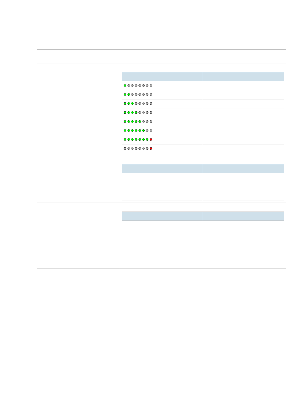
RSSI LEDs Indicates the received signal strength.
W.LINK LED Indicates when the subscriber unit is connected with a base station.
and power, refer to Section2.7, “Connecting Power and Data”.
connecting the antennas, refer to Section2.5, “Installing the Antennas”.
LED RSSI Level
< -90
-85 to -90
-80 to -85
-75 to -80
-70 to -75
-65 to -70
-20 to -60
> -20
State Description
Green (Solid) Subscriber unit is connected to the base
station and receiving services.
Green (Blinking) Link between the subscriber unit and the
PWR LED Indicates when power is supplied to the subscriber unit.
State Description
Green Power is on.
Off Power is off.
ETH Port A 4-pin, female, D-Coded M12 port for data.
Chassis Ground Connection Protects the subscriber unit from power surges and accumulated static electricity. For
information about grounding the subscriber unit, refer to Section2.6, “Grounding the
Subscriber Unit”.
base station is down.
Section1.3
Required Tools and Materials
The following tools and materials are required to install the RUGGEDCOM WIN5114-V:
Tools
• Wrench or socket set
• Phillips screwdriver
• Drill with an 8 mm (5/16 in) drill bit
• Wall anchors (if necessary)
Greases
• Marine grease (for marine applications only)
Tapes
• POE cold shrink (maximum 49.2 mm or 1.9 in inner
diameter before shrinking) or self-amalgamating tape
Required Tools and Materials 3
Page 10

Chapter 1
Introduction
RUGGEDCOM WIN5114-V
Installation Guide
Sprays
• Cleaner and de-greaser
• SCC3 conformal coating
• Corrosion protection
Section1.4
• UV-resistant vinyl tape
• Electrical insulation putty
Mounting Hardware (Wall/Tower Only)
• Four 1/4" × 1/2" HEX chipboard screws
• Four 1/4" flat washers
• Four 1/4" spring washers
Decommissioning and Disposal
Proper decomissioning and disposal of this device is important to prevent malicious users from obtaining
proprietary information and to protect the environment.
Decommissioning
This device may include sensitive, proprietary data. Before taking the device out of service, either permanently or
for maintenance by a third-party, make sure it has been fully decommissioned.
For more information, refer to the associated User Guide.
Recycling and Disposal
For environmentally friendly recycling and disposal of this device and related accessories, contact a facility
certified to dispose of waste electrical and electronic equipment. Recycling and disposal must be done in
accordance with local regulations.
4 Decommissioning and Disposal
Page 11

RUGGEDCOM WIN5114-V
Installation Guide
Installing the Subscriber Unit
Installing the Subscriber Unit
This chapter describes how to install the subscriber unit, including mounting the subscriber unit, connecting
power, connecting the antenna, and connecting the subscriber unit to the network.
DANGER!
Electrocution hazard – risk of serious personal injury and/or damage to equipment. Before performing
any maintenance tasks, make sure all power to the subscriber unit has been disconnected and wait
approximately two minutes for any remaining energy to dissipate.
DANGER!
Electrocution hazard – risk of death or serious injury. When the subscriber unit is installed in an
outdoor location, all indoor components (e.g. Ethernet and power supply) should be connected
through a lightning protector.
Lightning protection protects people and equipment located indoors from lightning that may strike
the subscriber unit or its outdoor cables. Therefore, install the lightning protector indoors, as close
as possible to the point where the cables enter the building. The lightning protector can also be
installed outdoors as long as the cables that lead indoors are well protected from lightning between
the protector and the building entrance.
Chapter 2
WARNING!
Safety hazard – risk of serious personal injury and/or damage to equipment. Installing the
RUGGEDCOM WIN5114-V can pose a serious safety hazard. Be sure to take precautions to avoid the
following:
• Exposure to high voltage lines during installation
• Falling when working at heights or with ladders
• Injuries from dropping tools
• Contact with AC wiring (power system connection)
IMPORTANT!
Only certified personnel should be permitted to install equipment.
IMPORTANT!
This product contains no user-serviceable parts. Attempted service by unauthorized personnel shall
render all warranties null and void.
Changes or modifications not expressly approved by Siemens Canada Ltd could invalidate
specifications, test results, and agency approvals, and void the user's authority to operate the
equipment.
5
Page 12

Chapter 2
Installing the Subscriber Unit
IMPORTANT!
This product should be installed in a restricted access location where access can only be gained by
authorized personnel who have been informed of the restrictions and any precautions that must be
taken. Access must only be possible through the use of a tool, lock and key, or other means of security,
and controlled by the authority responsible for the location.
IMPORTANT!
Install equipment in accordance with the electrical code relevant to the country of installation, such as:
• the National Electrical Code (NEC), ANSI/NFPA 70
• the Canadian Electrical Code (CEC), Part 1, CSA C22.1
• the National Electrical Safety Code IEEE C2 (when applicable)
Unless marked or otherwise identified, the Standard for the Protection of Electronic Computer/Data
Processing Equipment, ANSI/NFPA 75, also applies.
IMPORTANT!
Outdoor exposed communication lines longer than 40 m (140 ft) must be considered as TNV-1 circuits.
The installer must make sure the power supply and network ports are designed for full compliance with
the standards for TNV-1 telecommunication networks.
RUGGEDCOM WIN5114-V
Installation Guide
CONTENTS
• Section2.1, “General Procedure”
• Section2.2, “Unpacking the Subscriber Unit”
• Section2.3, “Site Preparation and Precautions”
• Section2.4, “Mounting the Subscriber Unit”
• Section2.5, “Installing the Antennas”
• Section2.6, “Grounding the Subscriber Unit”
• Section2.7, “Connecting Power and Data”
• Section2.8, “Weatherproofing the Subscriber Unit”
Section2.1
General Procedure
The general procedure for installing the subscriber unit is as follows:
1. Review the relevant certification information for any regulatory requirements. For more information, refer to
Section5.1, “Approvals”.
2. Unpack and inspect the subscriber unit components. For more information, refer to Section2.2, “Unpacking
the Subscriber Unit”.
3. Mount the subscriber unit to a pole, wall or tower. For more information, refer to Section2.4, “Mounting the
Subscriber Unit”.
4. Install and connect the antenna(s). For more information, refer to Section2.5, “Installing the Antennas”.
5. Make sure the subscriber unit is grounded. For more information, refer to Section2.6, “Grounding the
Subscriber Unit”.
6 General Procedure
Page 13

RUGGEDCOM WIN5114-V
Installation Guide
6. Connect the subscriber unit to a power source and the network. For more information, refer to Section2.7,
“Connecting Power and Data”.
7. Seal all cable connections. For more information, refer to Section2.8, “Weatherproofing the Subscriber Unit”.
8. Configure the subscriber unit. For more information, refer to Section3.1, “Configuring the Subscriber Unit”.
Section2.2
Installing the Subscriber Unit
Unpacking the Subscriber Unit
The following items are included in the RUGGEDCOM WIN5114-V package:
Item Quantity
RUGGEDCOM WIN5114-V Subscriber Unit 1
Radio Frequency (RF) antenna cables, 5 m (16.4 ft) long 2
Pole/wall/tower mounting kit 1
When unpacking the subscriber unit, do the following:
1. Inspect the package for damage before opening it.
2. Visually inspect each item in the package for any physical damage.
3. Verify all items are included.
If any item is missing or damaged, contact Siemens for assistance.
Chapter 2
Section2.3
Site Preparation and Precautions
Before installing the subscriber unit and or antenna(s), it is important to plan the the complete installation and
make sure the appropriate safe guards are in place.
Site Selection
Consider the following recommendations when selecting an appropriate site for the subscriber unit and
antenna(s):
• Mount the antenna(s) at the highest point possible. Reception will increase according to the height of the
antenna(s).
• Mount the antenna(s) in a place with as few obstructions as possible between the antenna(s) and the planned
service area.
• To avoid interference, mount the antenna(s) and subscriber unit as far as possible from other antenna(s) and
subscriber units.
• Keep the cable from the subscriber unit to the antenna(s) as short as possible and mount the antenna(s) as
close as possible to the subscriber unit. Using a cable longer than 2 m (6.6 ft) will result in greater loss and more
interference, as the cable will act as an antenna itself.
• Do not point the antenna(s) directly at populated areas.
• Locate the antenna(s) at least 3.6 m (11.8 ft) from people and public areas.
Unpacking the Subscriber Unit 7
Page 14

Chapter 2
Installing the Subscriber Unit
• Make sure the antenna(s) and subscriber unit are easily accessible for maintenance purposes.
• Conduct a site survey to best position the subscriber unit and antenna(s) in relation to other subscriber units,
antennas and base stations in the area. The site survey should also take into consideration the overall safety of
the selected site
RUGGEDCOM WIN5114-V
Installation Guide
Site Survey
Most wireless networks include many subscriber/base stations installedin various locations in an overlapping
radio-cell pattern. It is important to position each subscriber unit in an optimal location considering the
assignment of its radio channels. Therefore, a site survey becomes an essential first step before physically
deploying the subscriber unit.
The site survey should include details important to the planning of the subscriber unit deployment in each specific
site, including potential mounting points for the subscriber unit and antennas, as well as the routing options for
data, power and antenna cables.
For safety, always consult with the local power utility as well. It is important to select a site that not only offers
maximum coverage, but is also safe for installers to work in.
Safety Precautions
When installing the subscriber unit or an antenna, make sure to adhere to the following safety precautions:
• Always install the subscriber unit with the help of a partner.
• Always use the most appropriate mounting method for the site and the equipment being installed. For
assistance, contact a Siemens representative.
• Always assume an overhead line can cause serious injury or death. Note that electric power lines and phone
lines look alike.
• Always wear the appropriate Personal Protective Equipment (PPE) for the task, including but not limited to
rubber boots, rubber gloves, hard hat, harness and lanyard, etc.
• Always use a ladder made of a non-conductive material, such as wood or fiberglass. Do not use a metal ladder.
• Always work under favorable conditions. Do not work on wet or windy days.
• If the subscriber unit or antenna begins to drop, step away immediately and allow it to fall. The subscriber unit,
cables, metal guy wires and pole (in the case of pole mount installations) are all excellent conductors. Any
contact between these components and an electrical power line will complete an electrical path through the
subscriber unit/antenna and the installer.
• If any part of the subscriber unit or an antenna comes in contact with an electrical power line, contact the local
power utility. Do not attempt to touch or remove the component.
Section2.4
Mounting the Subscriber Unit
The RUGGEDCOM WIN5114-V is designed for maximum mounting and display flexibility. It can be secured to a
bracket and then mounted to a pole, wall or tower.
NOTE
For detailed dimensions of the subscriber unit, refer to Section4.6, “Dimension Drawings”.
8 Mounting the Subscriber Unit
Page 15

RUGGEDCOM WIN5114-V
Installation Guide
When choosing the mounting location for the unit, consider the available mounting structures and antenna
clearance.
Installing the Subscriber Unit
Site Survey
Most wireless networks include many subscriber/base stations installedin various locations in an overlapping
radio-cell pattern. It is important to position each subscriber unit in an optimal location considering the
assignment of its radio channels. Therefore, a site survey becomes an essential first step before physically
deploying the subscriber unit.
The site survey should include details important to the planning of the subscriber unit deployment in each specific
site, including potential mounting points for the subscriber unit and antennas, as well as the routing options for
data, power and antenna cables.
Recommended Site Requirements
It is highly recommended the subscriber unit be mounted with as few obstructions as possible between itself and
the base station. The subscriber unit should be pointed in the direction of the designated server base station.
When choosing the ideal location, it is also important to take into consideration the overall area topology.
CONTENTS
• Section2.4.1, “Mounting the Subscriber Unit to a Wall or Tower”
Chapter 2
• Section2.4.2, “Mounting the Subscriber Unit to a Pole”
Section2.4.1
Mounting the Subscriber Unit to a Wall or Tower
Mount the subscriber unit to any wall or tower capable of supporting its weight. An outer wall on a roof or other
high location to avoid interference from other buildings or trees is preferred.
To mount the subscriber unit to a wall or tower, do the following:
1. Attach the subscriber unit to the mounting bracket.
Mounting the Subscriber Unit to a Wall or Tower 9
Page 16

Chapter 2
2
1
3
5
4
6
8
10
2
9
6
5
7
Installing the Subscriber Unit
RUGGEDCOM WIN5114-V
Installation Guide
Figure2:Mounting the Subscriber Unit to a Wall or Tower
1.Subscriber Unit 2.Mounting Kit 3.Wall Holder/Pole Mount 4.M8 × 25 mm Hex Screw 5.M8 Spring Washer 6.M8 Flat
Washer 7.M8 Nut 8.M5 Flat Washer 9.NS 1/4" × 1/2" HEX Chipboard Screw 10.Wall Anchor
2. Liberally apply an anti-corrosion spray to all galvanized steel components, including mounting brackets,
washers and screws.
3. Select a mounting location on the wall.
4. Place the mounting bracket on the wall and mark four mounting holes.
5. Drill four holes and insert a wall anchor into each hole.
6. Secure the mounting bracket to the wall with four 1/4" × 1/2" HEX screws, four spring washers, and four flat
washers.
7. Connect the arm bracket to the mounting bracket using a screw, spring washer, flat washer and nut. Make
sure the nut is hand tight
8. Connect the subscriber unit to the arm bracket using a screw, spring washer, flat washer and nut. Make sure
the nut is hand tight.
9. Make sure the subscriber unit is properly grounded according to local standards. For more information, refer
to Section2.6, “Grounding the Subscriber Unit”.
10. Tighten the screws connecting the arm bracket to the subscriber unit and mounting bracket. Make sure the
screws are torqued to 24 N·m (17.7 ft. lb.).
Section2.4.2
Mounting the Subscriber Unit to a Pole
The subscriber unit can be attached to any pipe or pole with a diameter of 44.5 to 254 mm (1.75 to 10 in).
To mount the subscriber unit to a pole, do the following:
10 Mounting the Subscriber Unit to a Pole
Page 17

RUGGEDCOM WIN5114-V
4
9
2
3
6
6
8
3 5 6
7
1
7
1
2
9
6
7
6
8
7
6
53
4
3
Installation Guide
1. Attach the subscriber unit to the mounting bracket.
Installing the Subscriber Unit
Chapter 2
Figure3:Mounting the Subscriber Unit to a Large Pole
1.Subscriber Unit 2.Pole 3.Clamping Bracket 4.Mounting Bracket 5.M8-25 Hex Screw 6.M8 Spring Washer 7.M8 Flat
Washer 8.M8 Nut 9.M8-70 Hex Screw
Figure4:Mounting the Subscriber Unit to a Small Pole
1.Subscriber Unit 2.Pole 3.Clamping Bracket 4.Mounting Bracket 5.M8-25 Hex Screw 6.M8 Spring Washer 7.M8 Flat
Washer 8.M8 Nut 9.M8-70 Hex Screw
2. Liberally apply an anti-corrosion spray to all galvanized steel components, including mounting brackets, nuts,
washers and screws.
Mounting the Subscriber Unit to a Pole 11
Page 18

Chapter 2
Installing the Subscriber Unit
3. Select a mounting location on the pole.
4. Position the mounting bracket against the pole.
RUGGEDCOM WIN5114-V
Installation Guide
NOTE
When mounting the subscriber unit, note the orientation of the clamping bracket in Figure 3 or
Figure 4.
5. Secure the clamping bracket to the mounting bracket using screws, spring washers and nuts. Make sure the
screws are hand tightened.
6. Make sure the subscriber unit is properly grounded according to local standards. For more information, refer
to Section2.6, “Grounding the Subscriber Unit”.
7. Tighten the screws connecting the clamping bracket to the mounting bracket. Make sure the screws are
torqued to 14 N·m (10 lbf-ft).
Section2.5
Installing the Antennas
The RUGGEDCOM WIN5114-V supports N-Connect female antennas.
To install an antenna, do the following:
WARNING!
Radiation hazard – risk of Radio Frequency (RF) exposure. This subscriber unit is compliant with the
requirements set forth in FCC CFR 47, section 1.1307, addressing Radio Frequency (RF) exposure from
radio frequency base stations, as defined in FCC OET Bulletin 65 [http://transition.fcc.gov/Bureaus/
Engineering_Technology/Documents/bulletins/oet65/oet65.pdf]. The emitted radiation should be as
little as possible. To achieve minimum RF exposure, install the subscriber unit when it is configured
not to transmit and set it to operational mode remotely, rather than having a technician enable
transmission on-site. For maintenance of the subscriber unit or other operations which require RF
exposure, the exposure should be minimized in time and according to the regulations set forth by the
country of installation or the Federal Communications Commission (FCC).
WARNING!
The subscriber unit must be placed at a distance of at least 20 cm (8 in) from all persons during normal
operation. The antennas used for this product must not be located or operating in conjunction with any
other antenna or transmitter, except in accordance with FCC multi-transmitter evaluation procedures.
IMPORTANT!
During antenna installation, observe the following:
• Always install the antenna at least 40 cm (16 in) from people and public areas.
• Antenna must be in a fixed position.
• Make sure the front of the antenna is always facing the base station. In some conditions, such as
when the line of sight to the subscriber unit is impeded, better reception may be achieved using a
reflected signal. In this case, direct the antenna towards the reflecting object, rather than towards
the base station.
• In some cases, the antenna may need to be tilted to make sure the level at which the subscriber unit
receives transmissions from the base station (and vice versa) is not too high. When only the last RSSI
LED is on, this indicates saturation and the received signal level is too high. This must be avoided,
12 Installing the Antennas
Page 19

RUGGEDCOM WIN5114-V
1
1
4
3
3
5
2
6
Installation Guide
Installing the Subscriber Unit
preferably by tilting the antenna upwards. As a general rule, if the subscriber unit is located at a
distance of less than 300 m (984 ft) from the base station, it is recommended to tilt the antenna
upwards by approximately 10 to 15°.
• After the antenna is installed, do not change the antenna position.
1. Mount the antenna to a pole or wall in an area that provides good signal coverage and is away from any
signal noise emanating from other communications equipment.
2. Position the antenna towards the general direction of the designated base station.
WARNING!
Fire hazard – risk of serious personal injury and/or damage to equipment. To reduce the risk of fire,
use only 26 AWG or larger telecommunication line cord between indoor and outdoor devices.
3. Using shielded coaxial cables, connect the antenna to the lightning protector. Make sure the cables are
routed away from any noise sources, such as Switch-Mode Power Supplies (SMPS).
Chapter 2
Figure5:Antenna and Lightning Protector Assembly
1.Drain Wire 2.RUGGEDCOM WIN5114-V 3.Shielded Coaxial Cable 4.Lightning Protector 5.Ground Wire 6.Antenna
4. Make sure the PWR LED on the subscriber unit is on.
5. Adjust the position of the antenna until the maximum RSSI link quality reading is achieved. A single RSSI LED
indicates the subscriber unit is at minimum synchronized with the base station. For information about the
RSSI LED indicators, refer to Section1.2, “Description”.
If the subscriber unit is not synchronized with the base station, make sure the subscriber unit is properly
configured. For more information, refer to the RUGGEDCOM WIN User Guide for the subscriber unit.
If the expected link quality still cannot be achieved, try to improve the reception quality by placing the
antenna at a higher point or in an alternate location.
6. Make sure the antenna is properly grounded according to local standards.
Section2.6
Grounding the Subscriber Unit
When connecting the ground cable to the subscriber unit, make sure to use a 10 AWG grounding cable and torque
the screw to 15 N·m (11 ft. lb.).
Grounding the Subscriber Unit 13
Page 20

Chapter 2
Installing the Subscriber Unit
DANGER!
Electrocution hazard – risk of death or serious injury. The system must be properly grounded to protect
against power surges and accumulated static electricity. It is the installer’s responsibility to install this
base station in accordance with the local electrical codes.
Section2.7
Connecting Power and Data
The RUGGEDCOM WIN5114-V requires a 9 to 36 VDC Class 2 power supply.
IMPORTANT!
When connecting a DC battery power supply, make sure to use a 36 VDC, 3 A, double-pole circuit
breaker as the main disconnecting device.
To connect a power supply to the subscriber unit, do the following:
1. Make sure the power supply is grounded. For more information, refer to Section2.6, “Grounding the
Subscriber Unit”.
RUGGEDCOM WIN5114-V
Installation Guide
CAUTION!
Crushing hazard – risk of damage to cables. Route all power supply cables so that people cannot
walk on them or place objects on or against them.
2. Connect the power supply to the M12 (4-pin, male, A-coded) PWR port on the subscriber unit.
3. Connect a CAT-5e cable between the ETH port on the subscriber unit and a router/switch.
Section2.8
Weatherproofing the Subscriber Unit
Most outdoor subscriber unit, antenna and cable problems are caused by coaxial cable connections loosened by
vibration, allowing moisture to penetrate the connector interface. Siemens strongly recommends weatherproofing
all outdoor cable connections to prevent the ingress of water and help secure connections.
Use cold shrink tubing or self-amalgamating tape, as well as UV-resistant tape and electrical insulation putty to
seal connections.
IMPORTANT!
Warranty is void if the subscriber unit is assembled without waterproof sealing or if the sealing is
removed from the connections.
IMPORTANT!
The method of weatherproofing described in this section must be completed on all external
connections. If surge arrestors are used, all associated connections and arrestors must be completely
wrapped with splicing tape or self-amalgamating tape.
CONTENTS
• Section2.8.1, “Weatherproofing a Cable”
14 Connecting Power and Data
Page 21

RUGGEDCOM WIN5114-V
Installation Guide
• Section2.8.2, “Applying Cold Shrink Tubing”
• Section2.8.3, “Applying Self-Amalgamating Tape”
Section2.8.1
Installing the Subscriber Unit
Weatherproofing a Cable
To weatherproof a cable, do the following:
IMPORTANT!
PVC tape, silicon sealant and glue are not recommended for weatherproofing, as these materials are
difficult to apply accurately and are difficult to remove.
1. Spray the cable end and connector with a cleaner and de-greaser, making sure to remove any excess with a
clean lint-free cloth.
2. Spray the cable end and connector with SCC3 conformal coating and allow them to dry fully (approximately 3
to 5 minutes depending on the ambient temperature).
3. Apply cold shrink or self-amalgamating tape to the connector end. For information about how to apply
these types of seals, refer to Section2.8.2, “Applying Cold Shrink Tubing” or Section2.8.3, “Applying Self-
Amalgamating Tape”.
4. Apply two layers of UV-resistant vinyl tape to the cable ends.
5. Apply electrical insulation putty around the very end of the cable to form a seal between it and the base
station.
6. If the subscriber unit is installed in a marine environment (e.g. wind farm substation, coastal tower, or marine
vessel) apply a coating of marine grease to all galvanized steel components, including mounting brackets,
nuts, washers and screws. This is in addition to the anti-corrosion spray applied during the mounting process.
Chapter 2
IMPORTANT!
Should a cable need to be replaced, make sure all surfaces are thoroughly cleaned with a cleaner and
de-greaser spray before connecting the new cable. No residue from the previous weatherproofing
materials should be evident on the connector or the subscriber unit chassis.
Section2.8.2
Applying Cold Shrink Tubing
To apply cold shrink tubing to a cable end, do the following:
1. Disconnect the cable and slide the tube over the connector end.
2. Reconnect the cable and slide the tube up to meet the subscriber unit chassis.
3. Hold the tube against the subscriber unit chassis and start rotating it clockwise while gently pulling out the
core. Stop rotating once the front end of the cold shrink has begun to form around the cable end.
4. Continue to remove the core in a counter-clockwise direction until it is completely removed.
Weatherproofing a Cable 15
Page 22

Chapter 2
Installing the Subscriber Unit
Section2.8.3
RUGGEDCOM WIN5114-V
Installation Guide
Applying Self-Amalgamating Tape
To apply self-amalgamating (or self-fusing) tape to a cable end, do the following:
IMPORTANT!
When applying self-amalgamating tape, make sure to stretch it to 2/3 of its original width to form a
tight seal.
1. Cut a strip of self-amalgamating tape approximately 50 cm (19.7 in) long.
2. Apply one end of the tape to the cable end and tightly wrap it around the cable once fully, making sure the
tape overlaps.
3. Tightly wrap the remainder of the tape down the cable, making sure the tape overlaps with each pass.
4. Repeat the previous steps to apply a second layer of tape.
16 Applying Self-Amalgamating Tape
Page 23

RUGGEDCOM WIN5114-V
Installation Guide
Device Management
Device Management
This section describes how to connect to and manage the subscriber unit.
CONTENTS
• Section3.1, “Configuring the Subscriber Unit”
Section3.1
Configuring the Subscriber Unit
Once the subscriber unit is installed and connected to the network, it must be configured. The RUGGEDCOM
WIN5114-V features a Web-based User Interface (UI) for all configuration management. For more information
about configuring the subscriber unit, refer to the RUGGEDCOM WIN Subscriber Unit User Guide associated with
the subscriber unit and the installed software release.
Chapter 3
Configuring the Subscriber Unit 17
Page 24

Chapter 3
Device Management
RUGGEDCOM WIN5114-V
Installation Guide
18 Configuring the Subscriber Unit
Page 25

RUGGEDCOM WIN5114-V
Installation Guide
Technical Specifications
This section provides important technical specifications related to the subscriber unit.
CONTENTS
• Section4.1, “Power Supply Requirements”
• Section4.2, “Power Consumption”
• Section4.3, “Radio and Modem Specifications”
• Section4.4, “Operating Environment”
• Section4.5, “Mechanical Specifications”
• Section4.6, “Dimension Drawings”
Technical Specifications
Chapter 4
Section4.1
Power Supply Requirements
The RUGGEDCOM WIN5114-V requires an external power supply that meets the following requirements:
Power Supply Type Class 2
Input Range 10 to 36 VDC
Section4.2
Power Consumption
Typical Power Consumption 12 W
Section4.3
Radio and Modem Specifications
Operating Frequency 1350 to 1525 MHz
Wireless Communication
Standard
Operating Mode Time-Division Duplexing (TDD)
Channel Bandwidths 3.5 MHz
Power Supply Requirements 19
IEEE 802.16e-2009
5 MHz
Page 26

Chapter 4
Technical Specifications
7 MHz
10 MHz
Frequency Resolution 250kHz
Transmission Mode for MIMO MRC/STC (downlink)
Antenna Type External RF
RUGGEDCOM WIN5114-V
Installation Guide
Number of Ports for External
Antenna(s)
Type of Ports for External
Antenna(s)
Maximum Transmit Power 0.5W
Transmit Power Level
(Adjustable)
Size of Fast Fourier Transform
(FFT) Channels
Type of Modulation QPSK, 16-QAM, 64-QAM
Dynamic Range (Receiver) -20 to 100 dBm
Dynamic Range (Transmitter) -20 to 27 dBm
2
N-Connect female
54dB
1024/512FFT
Section4.4
Operating Environment
The RUGGEDCOM WIN5114-V is rated to operate under the following environmental conditions.
Ambient Operating
Temperature
a
-40 to 75 °C (-40 to 167 °F)
Ambient Storage Temperature -40 to 75 °C (-40 to 167 °F)
Ambient Relative Humidity
Maximum Altitude 2000 m (6562 ft)
a
Measured from a 30 cm (12 in) radius surrounding the center of the enclosure
b
Non-condensing
b
5% to 95%
Section4.5
Mechanical Specifications
Weight 1.5 kg (3.3 lb)
Ingress Protection IP67
Enclosure Aluminum
20 Operating Environment
Page 27

RUGGEDCOM WIN5114-V
37.0
44.2
81.7
42.5
27.5
25.1
244.7
226.0
92.2
154.0
11.0
36.0
4.5
106.8
Installation Guide
Section4.6
Dimension Drawings
NOTE
All dimensions are in millimeters, unless otherwise stated.
Technical Specifications
Chapter 4
Figure6:Overall Dimensions
Dimension Drawings 21
Page 28

Chapter 4
Technical Specifications
RUGGEDCOM WIN5114-V
Installation Guide
22 Dimension Drawings
Page 29

RUGGEDCOM WIN5114-V
Installation Guide
Certification
The RUGGEDCOM WIN5114-V ODU SU has been thoroughly tested to guarantee its conformance with recognized
standards and has received approval from recognized regulatory agencies.
CONTENTS
• Section5.1, “Approvals”
• Section5.2, “Environmental Type Tests”
Section5.1
Approvals
Chapter 5
Certification
This section details the standards to which the RUGGEDCOM WIN5114-V complies.
CONTENTS
• Section5.1.1, “CSA”
• Section5.1.2, “European Union (EU)”
• Section5.1.3, “TÜV Rheinland”
• Section5.1.4, “IEEE”
• Section5.1.5, “RoHS”
Section5.1.1
CSA
This subscriber unit meets the requirements of the following Canadian Standards Association (CSA) standards:
• CAN/CSA-C22.2 No. 60950-1-07+A1:2011+A2:2014
Information Technology Equipment – Safety – Part 1: General Requirements (Bi-National Standard, with UL
60950-1)
• CAN/CSA-C22.2 No. 60950-22-07+GI1:2012
Information Technology Equipment – Safety – Part 22: Equipment to be Installed Outdoors (Bi-National
standard, with UL 60950-22)
Approvals 23
Page 30

Chapter 5
Certification
Section5.1.2
RUGGEDCOM WIN5114-V
Installation Guide
European Union (EU)
This subscriber unit is declared by Siemens Canada Ltd to comply with essential requirements and other relevant
provisions of the following EU directives:
• IEC/EN 60950-1
Information Technology Equipment – Safety – Part 1: General Requirements
Section5.1.3
TÜV Rheinland
This subscriber unit is certified by TÜV Rheinland to meet the requirements of the following standards:
• UL 60950-1:2007 R10.14
Information Technology Equipment – Safety – Part 1: General Requirements
• UL 60950-22:2007 R12.11
Information Technology Equipment – Safety – Part 22: Equipment to be Installed Outdoors
The subscriber unit is marked with a TÜV Rheinland marking and can be used throughout the European
community.
A copy of the TÜV Rheinland Declaration of Conformity is available from Siemens Canada Ltd. For contact
information, refer to “Contacting Siemens”.
Section5.1.4
IEEE
This subscriber unit complies with the Mobile WiMAX Forum Wave 2 requirements defined by the following
Institute of Electrical and Electronics Engineers (IEEE) standards:
• IEEE 802.16-2005
IEEE Standard for Local and Metropolitan Area Networks – Part 16: Air Interface for Fixed and Mobile Broadband
Wireless Access Systems – Amendment for Physical and Medium Access Control Layers for Combined Fixed and
Mobile Operation in Licensed Bands
Section5.1.5
RoHS
This device is declared by Siemens Canada Ltd to meet the requirements of the following RoHS (Restriction of
Hazardous Substances) directives for the restricted use of certain hazardous substances in electrical and electronic
equipment:
• China RoHS 2
Administrative Measure on the Control of Pollution Caused by Electronic Information Products
24 European Union (EU)
Page 31

RUGGEDCOM WIN5114-V
Installation Guide
A copy of the Material Declaration is available online at https://support.industry.siemens.com/cs/ww/en/
view/109738831.
Section5.2
Environmental Type Tests
The RUGGEDCOM WIN5114-V has passed the following environmental tests.
Test Description Test Levels
IEC 60068-2-1 Low Temperature -25 °C for 72 hours
-40 °C (-40 °F) for 16 hours
-40 °C (-40 °F) for 72 hours
IEC 60068-2-2 High Temperature 55 °C (131 °F) for 72 hours
60 °C (140 °F) for 16 hours
70 °C (158 °F) for 72 hours
Chapter 5
Certification
IEC 60068-2-11
MIL-STD-810F 509.4
IEC 60068-2-14 Temperature Change -10 to 45 °C (14 to 113 °F) @ 0.5 °C/min (0.9 °F/min) for 2 cycles
IEC 529 (IP65/IP67)
IEC 60068-2-6 Sine Vibration Velocity: 5 mm/s
IEC 60068-2-64
Random Vibration (Class 4M5) ASD: 0.04 m²/s³
Salt Fog 5% NaCI 35° 48h
-40 to -30 °C (-40 to -22 °F) @ 1 °C/min (1.8 °F/min) for 5 cycles
Water (Rain, Intensity) 0.01 m³/min (0.35 ft³/min @ 90 kPa (13 PSI) for 30 minutesIEC 60068-2-18
Water (Rain) 0.01 m³/min @ 90 kPa (13 PSI) for 15 minutes
Displacement: 1.5 mm
Acceleration: 2 m/s²
Frequency Range: 5 to 62 Hz, 62 to 200 Hz
3 Axes
Duration: 3x5 sweep
12 to 12 dB/oct
Frequency Range: 5 to 10 Hz, 10 to 50, 50 to 100 Hz
3 axes, 30 min per axes
Random Vibration ASD: 1 m²/s³
-3 dB/oct
Frequency Range: 5 to 20 Hz, 20 to 200 Hz
3 axes, 30 min per axes
IEC 60068-2-29
Shock (Class 4M5) Spectrum: Half sine
Duration: 11 ms
Accelerator: 50 m/s²
100 shocks in each direction
Shock Spectrum: Half sine
Duration: 6 ms
Accelerator: 180 m/s²
Environmental Type Tests 25
Page 32

Chapter 5
Certification
RUGGEDCOM WIN5114-V
Installation Guide
Test Description Test Levels
100 shocks in each direction
IEC 60068-2-32
Nebs: GR63
Free Fall Height: 1 m (3.3 ft)
One fall on 3 faces, 3 edges and 4 corners
30 °C (86 °F) @ 90 to 100% for 2 cyclesIEC 60068-2-30 Humidity (Cycling)
40 °C (104 °F) @ 90 to 100% for 2 cycles
26 Environmental Type Tests
 Loading...