

Page 1
Preface
RUGGEDCOM RX1511
Installation Guide
Introduction
Installing the Device
Communication Ports
Technical Specifications
Dimension Drawings
Certification
1
2
3
4
5
6
02/2016
RC1056-EN-04
Page 2

RUGGEDCOM RX1511
Installation Guide
Copyright © 2016 Siemens Canada Ltd.
All rights reserved. Dissemination or reproduction of this document, or evaluation and communication of its contents, is not authorized
except where expressly permitted. Violations are liable for damages. All rights reserved, particularly for the purposes of patent application or
trademark registration.
This document contains proprietary information, which is protected by copyright. All rights are reserved. No part of this document may be
photocopied, reproduced or translated to another language without the prior written consent of Siemens Canada Ltd..
Disclaimer Of Liability
Siemens has verified the contents of this document against the hardware and/or software described. However, deviations between the
product and the documentation may exist.
Siemens shall not be liable for any errors or omissions contained herein or for consequential damages in connection with the furnishing,
performance, or use of this material.
The information given in this document is reviewed regularly and any necessary corrections will be included in subsequent editions. We
appreciate any suggested improvements. We reserve the right to make technical improvements without notice.
Registered Trademarks
RUGGEDCOM™ and ROS™ are trademarks of Siemens Canada Ltd..
Linux® is the registered trademark of Linus Torvalds in the United States and other countries.
The registered trademark Linux® is used pursuant to a sublicense from LMI, the exclusive licensee of Linus Torvalds, owner of the mark on a
world-wide basis.
Other designations in this manual might be trademarks whose use by third parties for their own purposes would infringe the rights of the
owner.
Security Information
Siemens provides products and solutions with industrial security functions that support the secure operation of plants, machines, equipment
and/or networks. They are important components in a holistic industrial security concept. With this in mind, Siemens' products and solutions
undergo continuous development. Siemens recommends strongly that you regularly check for product updates.
For the secure operation of Siemens products and solutions, it is necessary to take suitable preventive action (e.g. cell protection concept)
and integrate each component into a holistic, state-of-the-art industrial security concept. Third-party products that may be in use should also
be considered. For more information about industrial security, visit http://www.siemens.com/industrialsecurity.
To stay informed about product updates as they occur, sign up for a product-specific newsletter. For more information, visit http://
support.automation.siemens.com.
Warranty
Siemens warrants this product for a period of five (5) years from the date of purchase, conditional upon the return to factory for maintenance
during the warranty term. This product contains no user-serviceable parts. Attempted service by unauthorized personnel shall render all
warranties null and void. The warranties set forth in this article are exclusive and are in lieu of all other warranties, performance guarantees
and conditions whether written or oral, statutory, express or implied (including all warranties and conditions of merchantability and fitness for
a particular purpose, and all warranties and conditions arising from course of dealing or usage or trade). Correction of nonconformities in the
manner and for the period of time provided above shall constitute the Seller’s sole liability and the Customer’s exclusive remedy for defective
or nonconforming goods or services whether claims of the Customer are based in contract (including fundamental breach), in tort (including
negligence and strict liability) or otherwise.
For warranty details, visit www.siemens.com/ruggedcom or contact a Siemens customer service representative.
ii
Page 3

RUGGEDCOM RX1511
Installation Guide
Contacting Siemens
Address
Siemens Canada Ltd.
Industry Sector
300 Applewood Crescent
Concord, Ontario
Canada, L4K 5C7
Telephone
Toll-free: 1 888 264 0006
Tel: +1 905 856 5288
Fax: +1 905 856 1995
E-mail
ruggedcom.info.i-ia@siemens.com
Web
www.siemens.com/ruggedcom
iii
Page 4

RUGGEDCOM RX1511
Installation Guide
iv
Page 5

RUGGEDCOM RX1511
Installation Guide
Table of Contents
Table of Contents
Preface ............................................................................................................... vii
Alerts ................................................................................................................................................ vii
Related Documents ............................................................................................................................ vii
Accessing Documentation .................................................................................................................. vii
Training ............................................................................................................................................ viii
Customer Support ............................................................................................................................. viii
Chapter 1
Introduction .......................................................................................................... 1
1.1 Feature Highlights ........................................................................................................................ 1
1.2 Description .................................................................................................................................. 2
Chapter 2
Installing the Device ............................................................................................ 5
2.1 Mounting the Device .................................................................................................................... 5
2.1.1 Mounting the Device on a DIN Rail .................................................................................... 6
2.1.2 Mounting the Device to a Panel ......................................................................................... 6
2.2 Connecting Power ........................................................................................................................ 7
2.2.1 Installing/Removing Power Supplies ................................................................................... 8
2.2.1.1 Installing a Power Supply ........................................................................................ 8
2.2.1.2 Removing a Power Supply ...................................................................................... 9
2.2.2 Connecting High AC/DC Power ........................................................................................ 10
2.2.3 Connecting Low DCPower ............................................................................................... 11
2.3 Connecting the Failsafe Alarm Relay ........................................................................................... 12
2.4 Grounding the Device ................................................................................................................. 12
2.5 Connecting to the Device ........................................................................................................... 13
2.6 Cabling Recommendations ......................................................................................................... 14
2.6.1 Protection On Twisted-Pair Data Ports .............................................................................. 14
2.6.2 Gigabit Ethernet 1000Base-TX Cabling Recommendations ................................................. 15
Chapter 3
Communication Ports ......................................................................................... 17
3.1 Copper Ethernet Ports ................................................................................................................ 18
3.2 Fiber Optic Ethernet Ports .......................................................................................................... 21
3.3 SFP Optic Ethernet Ports ........................................................................................................... 21
v
Page 6

Table of Contents
RUGGEDCOM RX1511
Installation Guide
3.3.1 Installing an SFP Optical Port .......................................................................................... 22
3.3.2 Removing an SFP Optical Port ......................................................................................... 23
3.4 WAN Modules ............................................................................................................................ 23
3.5 Serial Ports ................................................................................................................................ 25
3.6 Cellular Modem Modules ............................................................................................................ 26
3.6.1 Cellular Modem Installation Requirements ......................................................................... 28
3.6.2 Diversity Requirements .................................................................................................... 28
3.6.3 Supported Frequency Bands ............................................................................................ 28
3.6.4 Installing SIM Cards for GSM, EDGE and HSPA+ Cellular Modems .................................... 29
3.7 DDS (Digital Data Services) Modules .......................................................................................... 31
3.8 RUGGEDCOM APE Module ....................................................................................................... 32
3.9 Installing/Removing Modules ....................................................................................................... 33
3.9.1 Installing a Module .......................................................................................................... 33
3.9.2 Removing a Module ........................................................................................................ 34
3.10 Connecting Multiple RS485 Devices .......................................................................................... 34
Chapter 4
Technical Specifications ..................................................................................... 37
4.1 Power Supply Specifications ....................................................................................................... 37
4.2 Failsafe Relay Specifications ...................................................................................................... 38
4.3 Copper Serial Port Specifications ................................................................................................ 38
4.4 Copper Ethernet Port Specifications ............................................................................................ 38
4.5 Fiber Optic Ethernet Port Specifications ....................................................................................... 39
4.5.1 10Base-FL/100Base-SX Ethernet Optical Specifications ..................................................... 39
4.5.2 Fast Ethernet (100 Mbps) Optical Specifications ................................................................ 39
4.5.3 Gigabit Ethernet (1 Gbps) Optical Specifications ................................................................ 41
4.6 Cellular Modem Specifications .................................................................................................... 42
4.7 Operating Environment ............................................................................................................... 43
4.8 RUGGEDCOM APE Specifications .............................................................................................. 43
4.9 Mechanical Specifications ........................................................................................................... 43
Chapter 5
Dimension Drawings .......................................................................................... 45
Chapter 6
Certification ........................................................................................................ 47
6.1 Standards Compliance ............................................................................................................... 47
6.2 Agency Approvals ...................................................................................................................... 47
6.3 EMC and Environmental Type Tests ............................................................................................ 48
vi
Page 7
RUGGEDCOM RX1511
Installation Guide
Preface
This guide describes the RUGGEDCOM RX1511. It describes the major features of the device, installation,
commissioning and important technical specifications.
It is intended for use by network technical support personnel who are responsible for the installation,
commissioning and maintenance of the device. It is also recommended for use by network and system planners,
system programmers, and line technicians.
Alerts
The following types of alerts are used when necessary to highlight important information.
DANGER!
DANGER alerts describe imminently hazardous situations that, if not avoided, will result in death or
serious injury.
Preface
WARNING!
WARNING alerts describe hazardous situations that, if not avoided, may result in serious injury and/or
equipment damage.
CAUTION!
CAUTION alerts describe hazardous situations that, if not avoided, may result in equipment damage.
IMPORTANT!
IMPORTANT alerts provide important information that should be known before performing a procedure
or step, or using a feature.
NOTE
NOTE alerts provide additional information, such as facts, tips and details.
Related Documents
Other documents that may be of interest include:
• ROX II User Guide for the RX1511
Accessing Documentation
The latest user documentation for RUGGEDCOM RX1511 v is available online at www.siemens.com/ruggedcom.
To request or inquire about a user document, contact Siemens Customer Support.
Alerts vii
Page 8
Preface
RUGGEDCOM RX1511
Installation Guide
Training
Siemens offers a wide range of educational services ranging from in-house training of standard courses on
networking, Ethernet switches and routers, to on-site customized courses tailored to the customer's needs,
experience and application.
Siemens' Educational Services team thrives on providing our customers with the essential practical skills to make
sure users have the right knowledge and expertise to understand the various technologies associated with critical
communications network infrastructure technologies.
Siemens' unique mix of IT/Telecommunications expertise combined with domain knowledge in the utility,
transportation and industrial markets, allows Siemens to provide training specific to the customer's application.
For more information about training services and course availability, visit www.siemens.com/ruggedcom or
contact a Siemens sales representative.
Customer Support
Customer support is available 24 hours, 7 days a week for all Siemens customers. For technical support or
general information, contact Siemens Customer Support through any of the following methods:
Online
Visit http://www.siemens.com/automation/support-request to submit a Support Request (SR) or check
on the status of an existing SR.
Telephone
Call a local hotline center to submit a Support Request (SR). To locate a local hotline center, visit
http://www.automation.siemens.com/mcms/aspa-db/en/automation-technology/Pages/default.aspx.
Mobile App
Install the Industry Online Support app by Siemens AG on any Android, Apple iOS or Windows mobile
device and be able to:
• Access Siemens' extensive library of support documentation, including FAQs and manuals
• Submit SRs or check on the status of an existing SR
• Contact a local Siemens representative from Sales, Technical Support, Training, etc.
• Ask questions or share knowledge with fellow Siemens customers and the support community
viii Training
Page 9

RUGGEDCOM RX1511
Installation Guide
Introduction
The RUGGEDCOM RX1511 is a cost-efficient, rugged Layer 3 switch and router. The RX1511’s modular and field
replaceable platform can be equipped with WAN, serial, and Ethernet options, making it ideally suited for electric
power utilities, the industrial plant floor, and traffic control systems. The appliance’s compact form factor makes it
ideal for pole mount applications or installation in restricted spaces.
The RX1511 is designed to provide a high level of immunity to electromagnetic interference (EMI) and
heavy electrical surges typical of the harsh environments found in many industrial applications. An operating
temperature range of -40 to 85 °C (-40 to 185 °F) allows the RX1511 to be placed in almost any location.
The following sections provide more information about the RX1511:
• Section 1.1, “Feature Highlights”
• Section 1.2, “Description”
Section 1.1
Chapter 1
Introduction
Feature Highlights
Reliability in Harsh Environments
• Immunity to EMI and high voltage electrical transients
• -40 to 85 °C (-40 to 185 °F) operating temperature (no fans)
• Failsafe output relay for critical failure or error alarming
Physical Ports
• Field replaceable line modules
• Up to 12 100Base-FX ports
• Up to 12 10/100Base-TX ports
• Up to 6 10Base-FL/100Base-SX ports
• Up to 4 Gigabit Ethernet ports
• Up to 12 serial ports
• Up to 4 T1/E1 RJ48C ports or 2 E1 BNC ports
• Up to 2 DDS (Digital Data Services) ports
• Up to 2 cellular SMA antenna ports (HSPA/EVDO)
Universal Power Supply Options
• Single, removable power supply module
• Fully integrated power supplies (no external adapters)
• Input voltage ranges: 13-36 VDC and 37-72 VDC or 85-264 VAC and 88-300 VDC for worldwide operability
• CSA/UL 60950-1 safety approved to 85 °C (185 °F)
Feature Highlights 1
Page 10
Chapter 1
4
2
1
3
5 6
7
Introduction
Section 1.2
RUGGEDCOM RX1511
Installation Guide
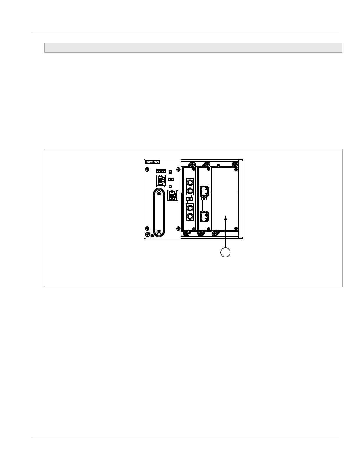
Description
The RX1511 features various ports, controls and indicator LEDs on the front panel for connecting, configuring and
troubleshooting the device.
Figure 1: RUGGEDCOM RX1511
1. Utility USB Port 2. RS232 Serial Console Port (RJ45) 3. Lamp Test/Alarm Cut-Off (LT/ACO) Button 4. Compact Flash Card Port
5. Alarm Indicator LED 6. Port Status LEDs 7. Management Port
• Management Port – This 10/100Base-T Ethernet port is used for system management that is out-of-band from
the switch fabric.
• RS-232 Serial Console Port – The serial console port is for interfacing directly with the device and accessing
initial management functions. For information about connecting to the device via the serial console port, refer to
Section 2.5, “Connecting to the Device”.
• Utility USB Port – Use the USB port to upgrade the ROX II software or install files, such as configuration
files and feature key files. For more information, refer to the RUGGEDCOM ROX II User Guide for the
RUGGEDCOM RX1511.
• Lamp Test/Alarm Cut-Off (LT/ACO) Button – This button performs two functions:
▪ Press and hold this button to test all indicator LEDs
▪ Press and release this button to acknowledge an active alarm
• Power Status LEDs – Indicate the status of the power modules.
▪ Green = Power is on
▪ Off = Power is off
• Port Status LEDs – Indicate when ports are active.
▪ Green = OK
▪ Orange = Warning alert
▪ Red = Configuration error
2 Description
Page 11
RUGGEDCOM RX1511
Installation Guide
• Alarm Indicator LED – Indicates when an alarm condition exists.
▪ Green = Alarms cleared/acknowledged
▪ Red = Alarm
• Compact Flash Card Port – Houses the 1 GB compact flash card that contains active and backup installations
of RUGGEDCOMROX II, along with the configuration database and other system data.
CAUTION!
Configuration hazard – risk of data corruption/loss. Do not open the compact flash card port, unless
specifically instructed to by a Siemens Customer Support representative. The warranty will be void
otherwise. Removing the compact flash card improperly can corrupt configuration data.
Chapter 1
Introduction
Description 3
Page 12

RUGGEDCOM RX1511
Installation Guide
Chapter 1
Introduction
Description 4
Page 13
RUGGEDCOM RX1511
Installation Guide
Installing the Device
Installing the Device
The following sections describe how to install the device, including mounting the device, connecting power, and
connecting the device to the network.
WARNING!
Radiation hazard – risk of serious personal injury. This product contains a laser system and is
classified as a CLASS 1 LASER PRODUCT. Use of controls or adjustments or performance of
procedures other than those specified herein may result in hazardous radiation exposure.
DANGER!
Electrocution hazard – risk of serious personal injury and/or damage to equipment. Before performing
any maintenance tasks, make sure all power to the device has been disconnected and wait
approximately two minutes for any remaining energy to dissipate.
IMPORTANT!
This product contains no user-serviceable parts. Attempted service by unauthorized personnel shall
render all warranties null and void.
Changes or modifications not expressly approved by Siemens Canada Ltd. could invalidate
specifications, test results, and agency approvals, and void the user's authority to operate the
equipment.
Chapter 2
IMPORTANT!
This product should be installed in a restricted access location where access can only be gained by
authorized personnel who have been informed of the restrictions and any precautions that must be
taken. Access must only be possible through the use of a tool, lock and key, or other means of security,
and controlled by the authority responsible for the location.
• Section 2.1, “Mounting the Device”
• Section 2.2, “Connecting Power”
• Section 2.3, “Connecting the Failsafe Alarm Relay”
• Section 2.4, “Grounding the Device”
• Section 2.5, “Connecting to the Device”
• Section 2.6, “Cabling Recommendations”
Section 2.1
Mounting the Device
The RX1511 is designed for maximum mounting and display flexibility. It can be equipped with connectors that
allow it to be installed in a 35 mm (1.4 in) DIN rail, or directly on a panel.
Mounting the Device 5
Page 14
Chapter 2
1
2
3
2
1
Installing the Device
RUGGEDCOM RX1511
Installation Guide
NOTE
For detailed dimensions of the device with either DIN rail or panel hardware installed, refer to
Chapter 5, Dimension Drawings.
The following sections describe the various methods of mounting the device:
• Section 2.1.1, “Mounting the Device on a DIN Rail”
• Section 2.1.2, “Mounting the Device to a Panel”
Section 2.1.1
Mounting the Device on a DIN Rail
For DIN rail installations, the RX1511 can be equipped with panel/DIN rail adapters pre-installed on each side of
the chassis. The adapters allow the device to be slid onto a standard 35 mm (1.4 in) DIN rail.
To mount the device to a DIN rail, do the following:
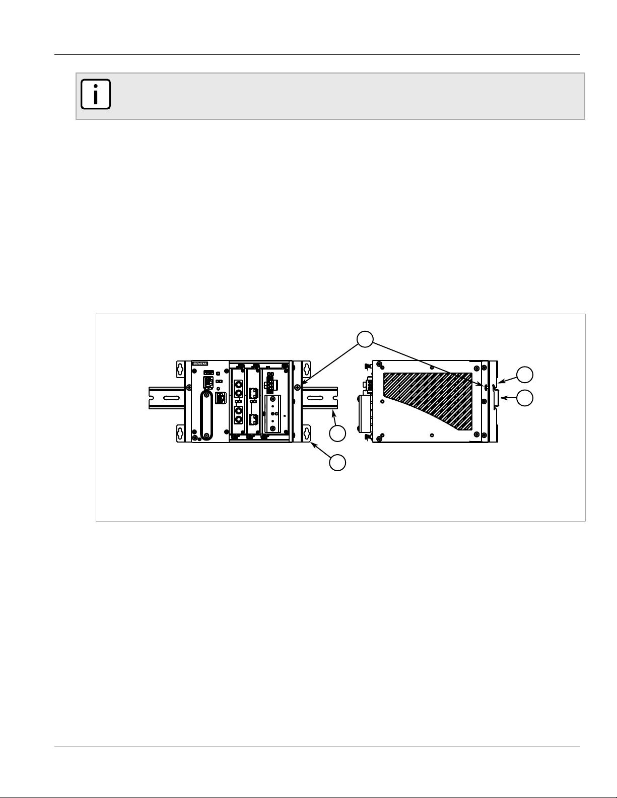
1. Align the adapters with the DIN rails and slide the device into place.
Figure 2: DIN Rail Mounting
1. Panel/DIN Rail Adapter 2. DIN Rail 3. Screw
2. Install one of the supplied screws on either side of the device to secure the adapters to the DIN rails.
Section 2.1.2
Mounting the Device to a Panel
For panel installations, the RX1511 can be equipped with panel/DIN rail adapters pre-installed on each side of the
chassis. The adapters allow the device to be attached to a panel using screws.
To mount the device to a panel, do the following:
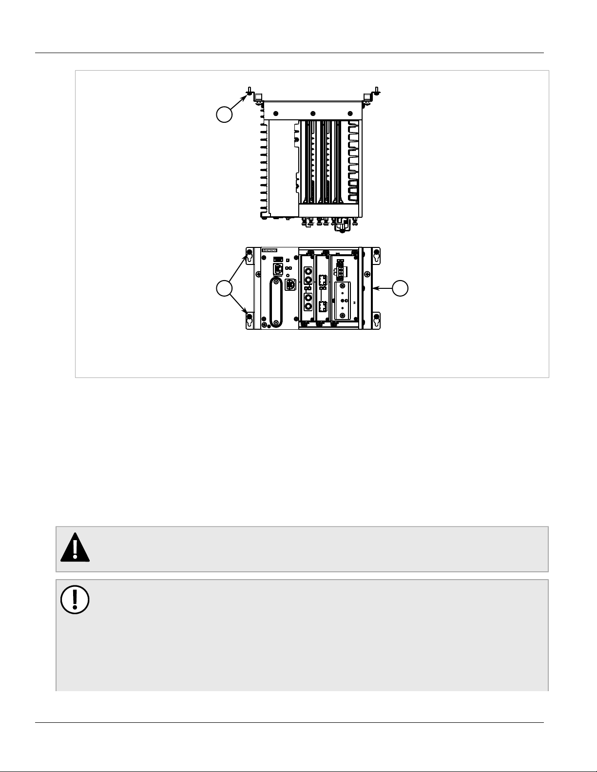
1. Place the device against the panel and align the adapters with the mounting holes.
6 Mounting the Device on a DIN Rail
Page 15
RUGGEDCOM RX1511
2
1
1
Installation Guide
Installing the Device
Chapter 2
Figure 3: Panel Mounting
1. Screw 2. Panel/DIN Rail Adapter
2. Install the supplied screws to secure the adapters to the panel.
Section 2.2
Connecting Power
The RX1511 supports a single high AC, high DC or low DC power supply.
The RX1511 can be equipped with either a screw-type or pluggable terminal block. The screw-type terminal
block is installed using Phillips screws and compression plates, allowing either bare wire connections or crimped
terminal lugs. Use #6 size ring lugs for secure, reliable connections under severe shock or vibration.
DANGER!
Electrocution hazard – risk of serious personal injury or death. Make sure the power source is off
before servicing the power supply terminal.
IMPORTANT!
• Use only #16 gage copper wiring when connecting terminal blocks.
• The maximum wire length between the terminal block and power source must not exceed 6 m (20 ft)
for 24 V power supplies or 18 m (60 ft) for 48 V power supplies.
• For 125/230 VAC rated equipment, an appropriately rated AC circuit breaker must be installed.
• For 125/250 VDC rated equipment, an appropriately rated DC circuit breaker must be installed.
• It is recommended to provide a 20 A circuit breaker for the power supply.
Connecting Power 7
Page 16
Chapter 2
1
Installing the Device
• Equipment must be installed according to applicable local wiring codes and standards.
The following sections describe how to connect power to the device:
• Section 2.2.1, “Installing/Removing Power Supplies”
• Section 2.2.2, “Connecting High AC/DC Power”
• Section 2.2.3, “Connecting Low DC Power”
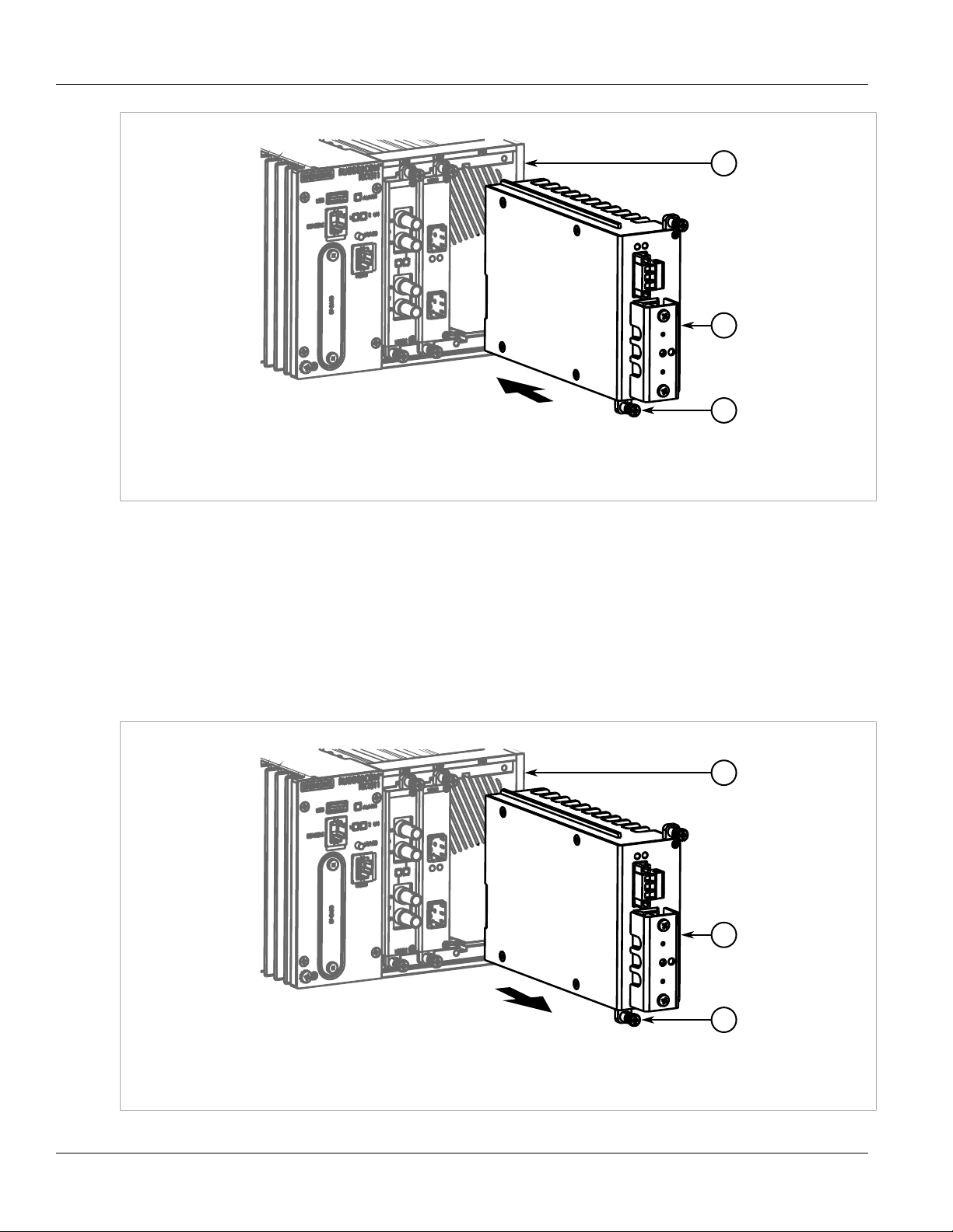
Section 2.2.1
Installing/Removing Power Supplies
The RX1511 supports a single AC or DC power supply.
RUGGEDCOM RX1511
Installation Guide
Figure 4: Power Module
1. Power Module
The following sections describe how to install, remove and connect the power supply:
• Section 2.2.1.1, “Installing a Power Supply”
• Section 2.2.1.2, “Removing a Power Supply”
Section 2.2.1.1
Installing a Power Supply
To install a power supply, do the following:
1. Remove the blank power module assembly or, if equipped, the currently installed power supply. For
information about removing a power supply, refer to Section 2.2.1.2, “Removing a Power Supply”.
2. Insert the power supply into the empty slot. When power is supplied to the device, the top and bottom LEDs
on the power supply should be green, indicating that power is being received and supplied to the device.
8 Installing/Removing Power Supplies
Page 17
RUGGEDCOM RX1511
1
2
3
1
2
3
Installation Guide
Figure 5: Installing a Power Supply
1. Chassis 2. Power Supply 3. Screws
Installing the Device
Chapter 2
3. Hand-tighten the screws to secure the power supply.
Section 2.2.1.2
Removing a Power Supply
To remove a power supply, do the following:
1. Remove the screws that secure the power supply.
2. Pull the power supply from the chassis.
Figure 6: Removing a Power Supply
1. Chassis 2. Power Supply 3. Screws
Removing a Power Supply 9
Page 18
Chapter 2
1
2
5434 53
Installing the Device
3. Install the blank power module assembly into the empy slot to prevent the ingress of dust and dirt.
Section 2.2.2
Connecting High AC/DC Power
To connect a high AC/DC power supply to the device, do the following:
DANGER!
Electrocution hazard – risk of death, serious personal injury and/or damage to the device. Make sure
the supplied cover is always installed over high voltage screw-type terminal blocks.
CAUTION!
Electrical hazard – risk of damage to equipment. Do not connect AC power cables to a 12, 24 or 48
VDC power supply terminal block. Damage to the power supply may occur.
NOTE
The screw-type terminal block is installed using Phillips screws and compression plates, allowing either
bare wire connections or crimped terminal lugs. Use #6 size ring lugs for secure, reliable connections.
RUGGEDCOM RX1511
Installation Guide
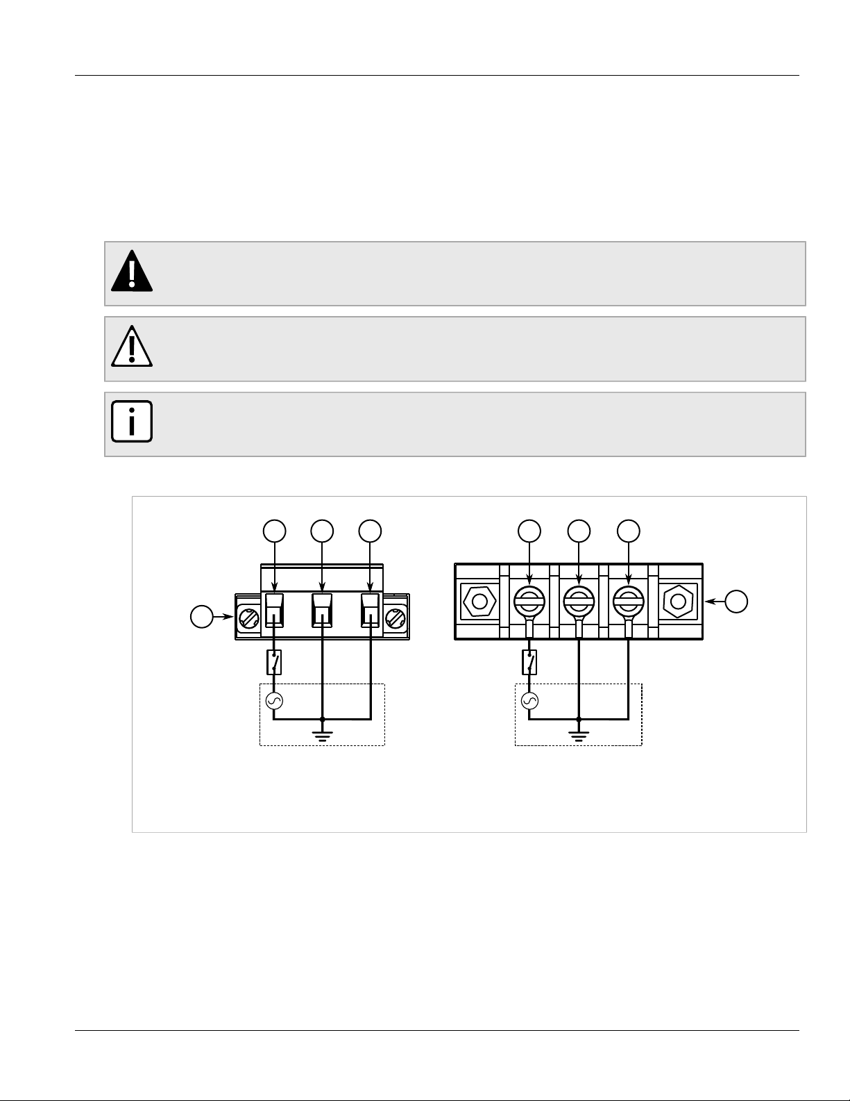
1. Connect the positive wire from the power source to the positive/live (+/L) terminal on the terminal block.
Figure 7: AC Terminal Block Wiring
1. Pluggable Terminal Block for HIP Power Supplies 2. Screw-Type Terminal Block for HI Power Supplies 3. Positive/Live (+/L)
Terminal 4. Ground Terminal 5. Negative/Neutral (-/N) Terminal
2. Connect the negative wire from the power source to the neutral/negative (-/N) terminal on the terminal block.
3. Using a braided wire or other appropriate grounding wire, connect the ground terminal to the chassis ground
connection. The ground terminal is used as the ground conductor for surge and transient suppression
circuitry internal to the unit.
4. Connect the ground terminal on the power source to the ground terminal on the device. For more
information, refer to Section 2.4, “Grounding the Device”.
10 Connecting High AC/DC Power
Page 19

RUGGEDCOM RX1511
+
+
1
2
5434 53
Installation Guide
Section 2.2.3
Connecting Low DC Power
To connect a low DC power supply to the device, do the following:
CAUTION!
Electrical hazard – risk of damage to equipment. Do not connect AC power cables to a 12, 24 or 48
VDC power supply terminal block. Damage to the power supply may occur.
IMPORTANT!
When connecting the device to a DC power source, make sure the source provides only positive
voltage.
NOTE
The screw-type terminal block is installed using Phillips screws and compression plates, allowing either
bare wire connections or crimped terminal lugs. Use #6 size ring lugs for secure, reliable connections.
1. Connect the positive wire from the power source to the positive (+) terminal on the terminal block.
Installing the Device
Chapter 2
Figure 8: DC Terminal Block Wiring
1. Pluggable Terminal Block for HI, 24P and 48P Power Supplies 2. Screw-Type Terminal Block for HIP, 24 and 48 Power Supplies
3. Positive (+) Terminal 4. Negative (-) Terminal 5. Ground Terminal
2. Connect the negative wire from the power source to the negative (-) terminal on the terminal block.
3. Using a braided wire or other appropriate grounding wire, connect the ground terminal to the chassis
ground connection. The surge ground terminal is used as the ground conductor for all surge and transient
suppression circuitry internal to the unit.
4. Connect the ground terminal on the power source to the chassis ground terminal on the device. For more
information, refer to Section 2.4, “Grounding the Device”.
Connecting Low DC Power 11
Page 20

Chapter 2
2 31
2
1
Installing the Device
Section 2.3
RUGGEDCOM RX1511
Installation Guide
Connecting the Failsafe Alarm Relay
The failsafe relay can be configured to latch based on alarm conditions. The NO (Normally Open) contact is
closed when the unit is powered and there are no active alarms. If the device is not powered or if an active alarm
is configured, the relay opens the NO contact and closes the NC (Normally Closed) contact.
NOTE
Control of the failsafe relay output is configurable through ROX II. One common application for this
relay is to signal an alarm if a power failure occurs. For more information, refer to the ROX II User
Guide for the RX1511.
The following shows the proper relay connections.
Figure 9: Failsafe Alarm Relay Wiring
1. Normally Open 2. Common 3. Normally Closed
Section 2.4
Grounding the Device
The RX1511 chassis ground terminal uses a #10-32 screw. It is recommended to terminate the ground
connection with a #10 ring lug and torque it to 3.4 N·m (30 lbf·in).
Figure 10: Chassis Ground Connection
1. #10-32 Screw 2. #10 Ring Lug
12 Connecting the Failsafe Alarm Relay
Page 21

RUGGEDCOM RX1511
18
Installation Guide
Installing the Device
Section 2.5
Connecting to the Device
The following describes the various methods for accessing the ROX II console and Web interfaces on the device.
For more detailed instructions, refer to the ROX II User Guide for the RX1511.
Serial Console and Management Ports
Connect a PC or terminal directly to the serial console or management ports to access the boot-time control and
ROX II interfaces. The serial console port provides access to ROX II's console interface, while the management
port provides access to ROX II's console and Web interfaces.
IMPORTANT!
The serial console and management (MGMT) ports are intended to be used only as temporary
connections during initial configuration or troubleshooting.
Connection to the console port is made using an RJ-45-to-DB9 console cable. The following is the pin-out for the
console port:
Pin
RJ-45
Male
1 6 DSR
DB9
Female
Name Description
a
Data Set Ready
Chapter 2
2 1 Reserved (Do Not Connect)
Figure 11: RJ-45 Console Port Pin Configuration
a
The DSR, DCD and DTR pins are connected together internally.
b
The CTS and RTS pins are connected together internally.
c
RI is not connected.
3 4 DTR
4 5 GND Signal Ground
5 2 RxD Receive Data (to DTE)
6 3 TxD Transmit Data
7 8 CTS
8 7 RTS
9 RI
a
b
b
c
Data Terminal Ready
(from DTE)
Clear to Send
Read to Send
Ring Indicator
For information about how to connect to the device via the serial console port, refer to the RUGGEDCOM ROX II
CLI User Guide for the RX1511.
For information about how to connect to the device via the management port, refer to either the RUGGEDCOM
ROX II Web Interface User Guide or the RUGGEDCOM ROX II CLI User Guide for the RX1511.
The management port is a 10/100Base-TX copper Ethernet port with an RJ-45 connector. The following is the
pin-out for the management port:
Connecting to the Device 13
Page 22

Chapter 2
18
Installing the Device
RUGGEDCOM RX1511
Installation Guide
Pin Name Description
1 RX+ Receive Data+
2 RX- Receive Data-
3 TX+ Transmit Data+
Figure 12: RJ-45 Management Port
4 Reserved (Do Not Connect)
5 Reserved (Do Not Connect)
6 TX- Transmit Data-
7 Reserved (Do Not Connect)
8 Reserved (Do Not Connect)
Communication Ports
Connect any of the available Ethernet ports on the device to a management switch and access the ROX II
console and Web interfaces via the device's IP address. The factory default IP address for the RUGGEDCOM
RX1511 is https://192.168.0.2.
For more information about available ports, refer to Chapter 3, Communication Ports.
Section 2.6
Cabling Recommendations
Siemens recommends using SIMATIC NET industrial Ethernet shielded cables for all Ethernet ports.
Refer to the following sections for further recommendations and considerations:
• Section 2.6.1, “Protection On Twisted-Pair Data Ports”
• Section 2.6.2, “Gigabit Ethernet 1000Base-TX Cabling Recommendations”
Section 2.6.1
Protection On Twisted-Pair Data Ports
All copper Ethernet ports on RUGGEDCOM products include transient suppression circuitry to protect against
damage from electrical transients and conform with IEC 61850-3 and IEEE 1613 Class 1 standards. This
means that during a transient electrical event, communications errors or interruptions may occur, but recovery is
automatic.
Siemens also does not recommend using copper Ethernet ports to interface with devices in the field across
distances that could produce high levels of ground potential rise (i.e. greater than 2500 V), during line-to-ground
fault conditions.
14 Cabling Recommendations
Page 23

RUGGEDCOM RX1511
Installation Guide
Section 2.6.2
Installing the Device
Gigabit Ethernet 1000Base-TX Cabling Recommendations
The IEEE 802.3ab Gigabit Ethernet standard defines 1000 Mbit/s Ethernet communications over distances of up
to 100 m (328 ft) using all 4 pairs in category 5 (or higher) balanced, unshielded twisted-pair cabling. For wiring
guidelines, system designers and integrators should refer to the Telecommunications Industry Association (TIA)
TIA/EIA-568-A wiring standard that characterizes minimum cabling performance specifications required for proper
Gigabit Ethernet operation. For reliable, error-free data communication, new and pre-existing communication
paths should be verified for TIA/EIA-568-A compliance.
The following table summarizes the relevant cabling standards:
Chapter 2
Cabling Category
< 5 No New wiring infrastructure required.
5 Yes Verify TIA/EIA-568-A compliance.
5e Yes No action required. New installations should be designed with Category 5e or higher.
6 Yes No action required.
> 6 Yes Connector and wiring standards to be determined.
1000Base-
TX Compliant
Required Action
Follow these recommendations for copper data cabling in high electrical noise environments:
• Data cable lengths should be as short as possible, preferably 3 m (10 ft) in length. Copper data cables should
not be used for inter-building communications.
• Power and data cables should not be run in parallel for long distances, and should be installed in separate
conduits. Power and data cables should intersect at 90° angles when necessary to reduce inductive coupling.
Gigabit Ethernet 1000Base-TX Cabling
Recommendations 15
Page 24

RUGGEDCOM RX1511
Installation Guide
Installing the Device
Chapter 2
Gigabit Ethernet 1000Base-TX Cabling
Recommendations 16
Page 25

RUGGEDCOM RX1511
1
2
Installation Guide
Communication Ports
Communication Ports
The RX1511 can be equipped with various types of communication ports to enhance its abilities and
performance. Each set of communication ports is part of a field replaceable module that makes switching ports
fast and easy.
Use the ROX II software to determine which ports are equipped on the device. For more information, refer to the
ROX II User Guide for the RX1511.
Modules can be installed in any one of the available slots in the RX1511 chassis.
NOTE
Only one T1/E1 module is allowed.
Chapter 3
Figure 13: Available Chassis Slots
1. Slot 1 2. Slot 2
The following sections describe the available ports in more detail:
• Section 3.1, “Copper Ethernet Ports”
• Section 3.2, “Fiber Optic Ethernet Ports”
• Section 3.3, “SFP Optic Ethernet Ports”
• Section 3.4, “WAN Modules”
• Section 3.5, “Serial Ports”
• Section 3.6, “Cellular Modem Modules”
• Section 3.7, “DDS (Digital Data Services) Modules”
• Section 3.8, “RUGGEDCOM APE Module”
• Section 3.9, “Installing/Removing Modules”
• Section 3.10, “Connecting Multiple RS485 Devices”
17
Page 26

Chapter 3
Communication Ports
Section 3.1
RUGGEDCOM RX1511
Installation Guide
Copper Ethernet Ports
The RX1511 supports several 10/100Base-TX Ethernet ports with RJ-45 or M12 (bypass or non-bypass)
connectors. The RJ-45 and M12 connectors are directly connected to the chassis ground on the device and can
accept CAT-5 shielded twisted-pair (STP) cables.
CAUTION!
Contamination hazard – risk of damage to equipment. M12 modules are shipped with internal O-rings
and dust caps to prevent the ingress of dirt and debris that may damage the port. Make sure the Orings and dust caps are installed on all unused M12 ports.
Figure 14: 2 × 10/100/1000TX with RJ-45 Ports
Figure 16: 2 x 8-Pin 10/100/1000TX with M12 A-Coded
Ports
Figure 18: 2 x 8-Pin 10/100/1000TX with M12 X-Coded
Ports
Figure 15: 6 × 10/100TX with RJ-45 Ports
Figure 17: 2 x 8-Pin 10/100/1000TX with M12 A-Coded
Bypass Ports
Figure 19: 2 x 8-Pin 10/100/1000TX with M12 X-Coded
Bypass Ports
Figure 20: 4 x 8-Pin 10/100TX with M12 A-Coded Ports
18 Copper Ethernet Ports
Figure 21: 4 x 8-Pin 10/100TX with M12 A-Coded Bypass
and Non-Bypass Ports
Page 27

RUGGEDCOM RX1511
18
Installation Guide
Communication Ports
Chapter 3
Figure 22: 4 x 4-Pin 10/100TX M12 D-Coded Ports
Figure 23: 4 x 4-Pin 10/100TX with M12 D-Coded Bypass
and Non-Bypass Ports
Each port features an LED that indicates the state of the port.
State Description
Green (Solid) Link established
Green (Blinking) Activity
Off No link detected
The following are the pin-out descriptions for the RJ-45 and M12 connectors:
Pin
Figure 24: RJ-45 Ethernet Port Pin Configuration
10/100Base-TX 1000Base-TX
1 RX+ BI_DA+ Receive Data+
2 RX- BI_DA- Receive Data-
3 TX+ BI_DB+ Transmit Data+
Name
Description
or Bi-Directional
Pair A+
or Bi-Directional
Pair A-
or Bi-Directional
Pair B+
4 Reserved (Do
Not Connect)
5 Reserved (Do
Not Connect)
6 TX- BI_DB- Transmit Data-
7 Reserved (Do
Not Connect)
8 Reserved (Do
Not Connect)
BI_DC+ Transmit Data+
or Bi-Directional
Pair C+
BI_DC- Receive Data-
or Bi-Directional
Pair C-
or Bi-Directional
Pair B-
BI_DD+ Receive Data-
or Bi-Directional
Pair D+
BI_DD- Receive Data-
or Bi-Directional
Pair D-
Copper Ethernet Ports 19
Page 28

Chapter 3
1 2
3
4
8
7
6 5
Communication Ports
RUGGEDCOM RX1511
Installation Guide
Figure 25: 8-Pin M12 A-Coded Ethernet Port Pin
Configuration
Pin 10/100Base-Tx Signal
1 Reserved (Do
Not Connect)
2 Reserved (Do
Not Connect)
3 Reserved (Do
Not Connect)
a
a
a
10/100/1000Base-
Tx Signal
4 TX- A-
5 RX+ B+
6 TX+ A+
7 Reserved (Do
Not Connect)
a
8 RX- B-
Pin 10/100/1000Base-Tx Signal
1 A+
2 A-
3 B+
C+
D+
D-
C-
4 B-
5 D+
Figure 26: 8-Pin M12 X-Coded Ethernet Port Pin
Configuration
6 D-
7 C+
8 C-
Pin 10/100Base-Tx Signal
1 TX+
2 RX+
3 TX-
4 RX-
Figure 27: 4-Pin M12 D-Coded Ethernet Port Pin
Configuration
a
Terminated at GND (Ground)
For specifications on the available copper Ethernet ports, refer to Section 4.4, “Copper Ethernet Port
Specifications”.
20 Copper Ethernet Ports
Page 29

RUGGEDCOM RX1511
21
21
21
21
21
Installation Guide
Section 3.2
Communication Ports
Fiber Optic Ethernet Ports
Fiber optic Ethernet ports are available with either MTRJ (Mechanical Transfer Registered Jack), LC (Lucent
Connector), SC (Standard or Subscriber Connector) or ST (Straight Tip) connectors. Make sure the Transmit (Tx)
and Receive (Rx) connections of each port are properly connected and matched to establish a proper link.
Chapter 3
Figure 28: MTRJ Port
1. Tx Connector 2. Rx Connector
Figure 30: SC Port
1. Tx Connector 2. Rx Connector
Figure 29: LC Port
1. Tx Connector 2. Rx Connector
Figure 31: ST Port
1. Tx Connector 2. Rx Connector
For specifications on the available fiber optic Ethernet ports, refer to Section 4.5, “Fiber Optic Ethernet Port
Specifications”.
Section 3.3
SFP Optic Ethernet Ports
SFP (Small Form-Factor Pluggable) optic Ethernet ports are available with LC (Lucent Connector) connectors.
Make sure the Transmit (Tx) and Receive (Rx) connections of each port are properly connected and matched to
establish a proper link.
Figure 32: LC Port
1. Tx Connector 2. Rx Connector
NOTE
SFP modules, as well as their optical ports, can be safely inserted and removed while the chassis is
powered and operating.
The following sections describe how to install and remove SFP optical ports:
Fiber Optic Ethernet Ports 21
Page 30

Chapter 3
2
1
Communication Ports
• Section 3.3.1, “Installing an SFP Optical Port”
• Section 3.3.2, “Removing an SFP Optical Port”
Section 3.3.1
Installing an SFP Optical Port
To install an SFP optical port, do the following:
CAUTION!
Electrical hazard – risk of damage to equipment. Use only components certified by Siemens with
RUGGEDCOM products. Damage to the module and device may occur if compatibility and reliability
have not been properly assessed.
CAUTION!
Electrical hazard – risk of damage to equipment. Make sure all electrostatic energy is dissipated
before installing or removing components from the device. An electrostatic discharge (ESD) can cause
serious damage to the component once it is outside the chassis.
1. Make sure all potential electrostatic build-up has been properly discharged to prevent electrostatic
discharges (ESD). This can be accomplished by wearing an ESD wrist strap or by touching Earth or the
chassis ground.
2. Remove the dust cover from the port opening in the module.
RUGGEDCOM RX1511
Installation Guide
CAUTION!
Mechanical hazard – risk of component damage. SFP optical ports are designed to insert in only
one orientation. Do not force the port into the module.
3. Remove the port from its packaging.
4. Insert the port into the module and swing the bail-latch up to lock it in place.
Figure 33: Installing an SFP Optical Port (Typical)
1. SFP Optical Port 2. Metal Bail-Latch
5. Remove the dust cover from the port.
6. Connect a cable to the port and test the connection.
22 Installing an SFP Optical Port
Page 31

RUGGEDCOM RX1511
2
1
Installation Guide
Section 3.3.2
Removing an SFP Optical Port
To remove an SFP optical port, do the following:
CAUTION!
Electrical hazard – risk of damage to equipment. Make sure all electrostatic energy is dissipated before
performing installing or removing components from the device. An electrostatic discharge (ESD) can
cause serious damage to the component once it is outside the chassis.
1. Make sure all potential electrostatic build-up has been properly discharged to prevent electrostatic
discharges (ESD). This can be accomplished by wearing an ESD wrist strap or by touching Earth or the
chassis ground.
2. Disconnect the cable from the port.
3. Swing the metal bail-latch down and pull the port from the module.
Communication Ports
Chapter 3
Figure 34: Removing an SFP Optical Port (Typical)
1. SFP Optical Port 2. Metal Bail-Latch
4. Store the port in an ESD-safe bag or other suitable ESD-safe environment, free from moisture and stored at
the proper temperature (-40 to 85 °C or -40 to 185 °F).
5. Insert a plug in the empty port opening to prevent the ingress of dust and dirt.
Section 3.4
WAN Modules
The RX1511 supports the following WAN (Wide Area Network) line modules:
NOTE
• Only one T1/E1 WAN module may be used per router.
• The TC1, TC2 and TC4 WAN modules comply with Part 68 of the FCC rules and requirements
adopted by ACTA. The product identifier is provided on a label on top of the modules. If requested,
this information must be provided to the telephone company.
• The TC1, TC2 and TC4 WAN modules meet the Industry Canada's CS-03 Part II, Issue 9 technical
specifications. The industry Canada registration number and model number is provided on a label on
top of the modules.
• The WAN modules TC1, TC2 and TC4 use only RJ48C connectors.
Removing an SFP Optical Port 23
Page 32

Chapter 3
Rx Tx
2
1
3
18
Communication Ports
• The modules have no user serviceable parts and equipment must only be repaired by authorized
Siemens personnel only.
RUGGEDCOM RX1511
Installation Guide
Figure 35: 1 × T1/E1 with RJ45 Ports (TC1)
Figure 37: 2 × T1/E1 with RJ45 Ports (TC2)
Figure 36: 1 × E1 with BNC Ports (E01)
Figure 38: 2 × E1 with BNC Ports (E02)
Figure 39: 4 × T1/E1 with RJ45 Ports (TC4)
The following is the pin-out for the BNC and RJ45 connectors:
Figure 40: RJ45 T1/E1 Pin Configuration
1. RTIP 2. TTIP 3. Chassis
Pin Name Description
1 RRING Receive Negative
2 RTIP Receive Positive
3 Reserved (Do Not Connect)
Figure 41: RJ45C T1/E1 Pin Configuration
24 WAN Modules
4 TRING Transmit Negative
5 TTIP Transmit Positive
6 Reserved (Do Not Connect)
7 Reserved (Do Not Connect)
Page 33

RUGGEDCOM RX1511
18
Installation Guide
Pin Name Description
8 Reserved (Do Not Connect)
Communication Ports
Section 3.5
Serial Ports
The RX1511 supports RJ45 serial ports that may be used with a null modem (crossover) serial cable.
Modes
Each serial port can be run in RS232, RS485 or RS422 mode.
On power-up, all serial ports default to RS485 mode. Each port can be individually set to RS232, RS485 or
RS422 mode through ROX II. For more information, refer to the ROX II User Guide for the RX1511.
LEDs
Chapter 3
All serial ports feature an LED that indicates the current state of the port.
State Description
Green Activity detected
Off No activity
Pin-Out
The following are the pin-outs for the RJ45 connectors:
Pin RS232 Mode RS485 Mode RS422 Mode
1 RX- (Receive
2 Reserved (Do Not Connect)
b
3
Figure 42: Serial RJ45 Port
b
4
5 RX (Receive) RX+ (Receive
6 TX (Transmit) TX/RX+
7 Note
8 Note
Common (Isolated) Ground
(Transmit/
Receive
TX/RX-
Receive
TX/RX-
c
e
Positive)
d
(Transmit/
Negative)
d
(Transmit/
Negative)
Negative)
TX+ (Transmit
Positive)
TX- (Transmit
Negative)
TX- (Transmit
Negative)
Serial Ports 25
Page 34

Chapter 3
Communication Ports
Pin RS232 Mode RS485 Mode RS422 Mode
Receive
Negative)
Shield Chassis Ground
b
Pins 3 and 4 are connected together internally.
c
15 kΩ pull-up resistor present on board.
d
Pins 7 and 8 are connected together internally to simulate RTS-CTS hardware flow control for the user.
e
In noisier environments, external pull-down resistors may be required for the negative terminal.
Connecting to RS485 Devices
For information about how to connect devices configured to run in RS485 mode, refer to Section 3.10,
“Connecting Multiple RS485 Devices”.
Specifications
For specifications on serial ports, refer to Section 4.3, “Copper Serial Port Specifications”.
RUGGEDCOM RX1511
Installation Guide
e
Section 3.6
Cellular Modem Modules
The RX1511 supports the following cellular modem line modules for operation on GSM, EDGE, HSPA+, or CDMA
networks:
DANGER!
Radio interference hazard – risk of death, serious personal injury or equipment damage. Do not
operate the cellular modem in the following areas:
• Areas where explosives are actively used
• In explosive atmospheres, such as refueling stations, fuel depots, chemical plants, underground
mining operations, etc.
• Near medical or life support equipment or devices
• In any aircraft, whether in flight or on the ground (unless permitted by the aircraft operator)
In such areas, the cellular modem must be turned off. Otherwise the cellular modem can transmit
signals that may interfere with nearby equipment that is susceptible to radio interference.
WARNING!
Communication disruption hazard – risk of serious personal injury, equipment damage, or data loss.
Wireless communications are susceptible to disruptions that may result in the delay, corruption or loss
of data. While cellular disruptions are uncommon when using a Siemens cellular modem, avoid using
the cellular modem in applications where a communication failure could result in damage to equipment
or personal injury to persons in the area. Siemens accepts no responsibility for any damages that may
result due to wireless disruptions.
26 Cellular Modem Modules
Page 35

RUGGEDCOM RX1511
12
2
3
3
1
Installation Guide
Communication Ports
Chapter 3
NOTE
The cellular modems feature 50 Ω SMA antenna connectors on the front plate of each module.
The HSPA option is available for use on various GSM-based networks. This option supports GSM,
GPRS, EDGE, UMTS and WCDMA/HSDPA/HSUPA. The Main antenna and Receive Diversity antenna
connections are made to the 50 Ω SMA connectors.
NOTE
If two or more antennas are to be installed, the antennas must be separated by a minimum distance of
20 cm (7.9 in).
IMPORTANT!
If the device is intended for use in a portable device, separate approval is required to satisfy the SAR
requirements of FCC Part 2.1093 and IC RSS-102.
Order Code Description
W11 1 Port Cell Modem GSM,EDGE,HSPA+
W21 1 Port Cell Modem EVDO Rev.A Verizon Wireless
Figure 43: W11 and W21 Cellular Modems
1. Main Antenna SMA Connector 2. Receive Diversity Antenna
SMA Connector
Order Code Description
W12 2 Port Cell Modem GSM,EDGE,HSPA+
W22 2 Port Cell Modem EVDO Rev.A Verizon Wireless
W32 1 Port Cell Modem GSM,EDGE,HSPA+, 1 Port
Cell Modem EVDO Rev.A Verizon Wireless
Figure 44: W12, W22 and W32 Cellular Modems
1. Main Antenna SMA Connector 2. Receive Diversity Antenna
SMA Connector 3. Antenna for First/Primary Cell Modem
The following sections describe the cellular modem modules in more detail:
• Section 3.6.1, “Cellular Modem Installation Requirements”
• Section 3.6.2, “Diversity Requirements”
• Section 3.6.3, “Supported Frequency Bands”
• Section 3.6.4, “Installing SIM Cards for GSM, EDGE and HSPA+ Cellular Modems”
Cellular Modem Modules 27
Page 36

Chapter 3
Communication Ports
Section 3.6.1
RUGGEDCOM RX1511
Installation Guide
Cellular Modem Installation Requirements
The cellular modem module is approved for modular use in mobile applications. The module, as part of the
RUGGEDCOM RX1511, can be integrated into a final product without additional certification from the Federal
Communications Commission (FCC) or Industry Canada (IC) if the application meets the following requirements:
NOTE
If this module is integrated into a portable device, separate approval related to the Specific Absorption
Rate (SAR) requirements of FCC Part 2.1093 and IC RSS-102 is required.
• Persons in the area must be kept at least 20 cm (8 in) from the antenna at all times.
• The antenna gain, including cable loss, must not exceed the maximum rating specified in Section 3.6.3,
“Supported Frequency Bands”.
• The cellular modem and antenna must not be next to or operate in conjunction with another transmitter or
antenna within a host device.
• A label must be affixed to the end product that indicates the FCC and IC IDs for the cellular modem.
Cellular Modem FCC ID IC ID
W11, W12 N7MC8705 2417C-MC8705
W21, W22 N7MC5728 2417C-MC5728
W32 N7MC8705 and N7MC5728 2417C-MC8705 and 2417C-MC5728
• The user documentation for the end product must clearly indicate the operating requirements and conditions
that comply with current FCC and IC radio frequency exposure guidelines.
• The end product must comply with the unintentional emission testing requirements of FCC Part 15.
If the application does not meet these requirements, further certification is required.
Section 3.6.2
Diversity Requirements
Diversity, where two antennas exist within the same physical housing, is a method for improving radio signal
strength. When two antennas are present, the following requirements must be met:
• Antenna isolation must be minimum 10 dB to prevent the receive antenna from picking up too much power
from the transmit antenna.
• Performance characteristics of the transmit and receive antennas must be comparable.
• The performance of the receive antenna, as measured by forward link throughput, must be 0 to 3 dB better
than a single antenna.
Section 3.6.3
Supported Frequency Bands
The following frequency bands are supported by the available cellular modem modules.
28 Cellular Modem Installation Requirements
Page 37

RUGGEDCOM RX1511
Installation Guide
Communication Ports
Chapter 3
WARNING!
Electromagnetic radiation hazard – risk of serious injury. Do not exceed the maximum antenna gain.
Aside from causing cellular interference for other devices that use the same band, adverse health
effects for individuals in the area may occur.
Band
Band I
WCDMA 2100
Band II
WCDMA 1900
Band VIII
WCDMA 900
Band V
WCDMA 850
Band VI
WCDMA 800
GSM 850 824-849 < 2.5:1 869-894 < 3.5:1
EGSM 900 880-915 < 2.5:1 925-960 < 3.5:1
GSM 1800 1710-1785 < 2.5:1 1805-1880 < 3.5:1
GSM 1900 1850-1910 < 2.5:1 1930-1990 < 2.5:1
f
Gain limits are reported on certification grants, for consideration against Radio Frequency (RF) exposure and Effective Radiated Power (ERP)/Effective Isotropic
Radiated Power (EIRP) limits.
Tx (MHz) VSWR Rx (MHz) VSWR
1920-1980 < 2.5:1 2110-2170 < 3.5:1
1850-1910 < 2.5:1 1930-1990 < 2.5:1
880-915 < 2.5:1 925-960 < 3.5:1
824-849 < 2.5:1 869-894 < 3.5:1
830-840 < 2.5:1 875-885 < 3.5:1
Frequency Range
RX Diversity
Support
ü
ü
ü
ü
ü
û
û
û
û
Maximum
Allowable
Gain (dBi)
4
4
5
5
5
5
5
4
4
f
Section 3.6.4
Installing SIM Cards for GSM, EDGE and HSPA+ Cellular Modems
To install a SIM card in a GSM, EDGE or HSPA+ cellular modem, do the following:
CAUTION!
Static electricity hazard – risk of damage to equipment. Make sure to take appropriate anti-static
precautions before opening the cellular modem module.
NOTE
The RUGGEDCOM RX1511 only supports mini-SIM cards (2FF size format.
1. Remove the module from the chassis.
2. On the smooth side of the module, remove the four screws and separate the back of the module from the
module chassis.
Installing SIM Cards for GSM, EDGE and HSPA+ Cellular
Modems 29
Page 38

Chapter 3
1
2
1
Communication Ports
Figure 45: W11, W21 Cellular Modem
1. SIM Card Cage 1
RUGGEDCOM RX1511
Installation Guide
Figure 46: W12, W22, W32 Cellular Modem
1. SIM Card Cage 1 2. SIM Card Cage 2
3. Open SIM card cage 1 by sliding the silver catch towards the antenna connectors and flip the cage up.
4. Insert a mini-SIM card into the cage.
5. Close SIM card cage 1 by flipping the cage down and slide the silver catch away from the antenna
connectors.
6. For W12, W22 and W32 cellular modems, repeat Step 3 to Step 5 install a mini-SIM card in SIM card cage 2.
7. Install the back of the module and secure it to the module chassis with the four screws removed previously.
8. Install the module. For more information, refer to Section 3.9.1, “Installing a Module”.
Installing SIM Cards for GSM, EDGE and HSPA+ Cellular
30
Modems
Page 39

RUGGEDCOM RX1511
1
2
Installation Guide
Section 3.7
Communication Ports
DDS (Digital Data Services) Modules
The RX1511 can be equipped with a DDS port line module that supports 56 kbps (Master/Slave) and 64 kbps
(Slave) line rates.
Figure 47: 1 × DDS with RJ-48S Ports (D02)
1. Rx LED 2. Tx LED
Chapter 3
Standards and Operating Modes
The module is compatible with the following standards:
• AT&T PUB 62310 (Standard DDS)
• BELLCORE TA-TSY-000077
• BELLCORE TR-TSY-000458
• ANSI T1.410
It also supports the following operating modes, which are configurable via the RUGGEDCOM ROX II user
interface:
Operating Mode Line Rate
DDS-PRI 56 kbps
CC-64K 72 kbps
LEDs
Each RJ-48S port features a RX and TX LED that indicates the state of the port.
LED LED Color Status
Rx
Tx
Green Connection established
Rx The interface is receiving an OOF (Out of Frame) alarm.
Tx
Rx Red The interface is receiving an ALOS (Alarm Loss of Signal) or Red alarm (e.g.
DDS (Digital Data Services) Modules 31
Yellow
The interface is in loopback mode.
corruption or loss of signal, connectivity loss, or no knowledge of connectivity).
Page 40

Chapter 3
18
Communication Ports
LED LED Color Status
RUGGEDCOM RX1511
Installation Guide
Tx The interface is receiving or transmitting an RAI (Remote Alarm Indication) or AIS
Rx
Tx
Off The interface is disabled.
(Alarm Indication Signal) alarm.
Pin-Out
The following is the pin-out for the DDS RJ-48S ports:
Figure 48: DDS RJ-48S Pin
Pin Name Description
1 R1 Transmit data to
network (Ring 1)
2 T1 Transmit data to network (Tip 1)
3 Reserved (Do Not Connect)
4 Reserved (Do Not Connect)
5 Reserved (Do Not Connect)
6 Reserved (Do Not Connect)
7 T Receive data from
network (Ring)
8 R Receive data from network (Tip)
Section 3.8
RUGGEDCOM APE Module
The RX1511 supports various versions of the RUGGEDCOM APE (Application Processing Engine) module. The
APE is an x86-based computer design that can host a variety of x86-based operating systems. It also features
Gigabit Ethernet (GbE) ports, USB ports and a DVI-D video port. For more information about RX1511 APE,
including installation and setup instructions, refer to the RUGGEDCOM APE User Guide.
CAUTION!
Electrical hazard – risk of power failure. Installing more APE modules than allowed can lead to power
fluctuations and irregular shut downs. Do not install more than two APE modules on the device.
Figure 49: RUGGEDCOM APE Module
For specifications, refer to Section 4.8, “RUGGEDCOM APE Specifications”.
32 RUGGEDCOM APE Module
Page 41

RUGGEDCOM RX1511
2
1
3
Installation Guide
Section 3.9
Communication Ports
Installing/Removing Modules
The following sections describe how to install and remove modules:
• Section 3.9.1, “Installing a Module”
• Section 3.9.2, “Removing a Module”
Section 3.9.1
Installing a Module
Upon installing a new module in the device, all the features associated to the module are available in the
operating system. For more information, refer to the ROX II User Guide for the RX1511.
To install a module, do the following:
1. Make sure power to the device has been disconnected and wait approximately two minutes for any
remaining energy to dissipate.
2. If the device is installed in a rack, remove it from the rack.
3. Remove the current module from the slot. For more information, refer to Section 3.9.2, “Removing a Module”.
4. Insert the new module into the slot.
Chapter 3
Figure 50: Installing a Module
1. Module 2. Chassis 3. Screw
5. Tighten the screws to secure the module.
6. If necessary, install the device in the rack.
7. Connect power to the device.
Installing/Removing Modules 33
Page 42

Chapter 3
2
1
3
Communication Ports
Section 3.9.2
RUGGEDCOM RX1511
Installation Guide
Removing a Module
Once a module is removed, all the features associated with the module are hidden or disabled in the operating
system.
To remove a module, do the following:
1. Make sure power to the device has been disconnected and wait approximately two minutes for any
remaining energy to dissipate.
2. If the device is installed in a rack, remove it from the rack.
3. Loosen the screws that secure the module.
4. Pull the module from the chassis to disconnect it.
Figure 51: Installing a Module
1. Module 2. Chassis 3. Screw
5. Install a new module or a blank module (to prevent the ingress of dust and dirt). For more information, refer
to Section 3.9.2, “Removing a Module”.
6. If necessary, install the device in the rack.
7. Connect power to the device.
Section 3.10
Connecting Multiple RS485 Devices
Each RS485 port can communicate with multiple RS485 devices by wiring devices together in sequence over a
single twisted pair with transmit and receive signals on the same two wires (half duplex). For reliable, continuous
communication, adhere to the following guidelines:
• To minimize the effects of ambient electrical noise, use shielded cabling.
• The correct polarity must be observed throughout a single sequence or ring.
34 Removing a Module
Page 43

RUGGEDCOM RX1511
< 1219 m (4000 in)
120Ω 10nF
120Ω 10nF
1
2
3
5
5
6
4
Installation Guide
Communication Ports
• The number of devices wired should not exceed 32, and total distance should be less than 1219 m (4000 ft) at
100 kbps.
• The Common terminals should be connected to the common wire inside the shield.
• The shield should be connected to earth ground at a single point to avoid loop currents.
• The twisted pair should be terminated at each end of the chain.
The following shows the recommended RS485 wiring.
Chapter 3
Figure 52: Recommended RS485 Wiring
1. RX1511 Device 2. Common (Isolated Ground) 3. Negative 4. Positive 5. Shield to Earth (Connected At a Single Point)
6. RS485 Devices (32 Total)
NOTE
A 15 kΩ pull-up resistor is present on board for the positive terminal.
In noisy environments, additional pull-down resistors may be required for the negative terminal.
Connecting Multiple RS485 Devices 35
Page 44

RUGGEDCOM RX1511
Installation Guide
Communication Ports
Chapter 3
Connecting Multiple RS485 Devices 36
Page 45

RUGGEDCOM RX1511
Installation Guide
Technical Specifications
Technical Specifications
The following sections provide important technical specifications related to the device and available modules:
• Section 4.1, “Power Supply Specifications”
• Section 4.2, “Failsafe Relay Specifications”
• Section 4.3, “Copper Serial Port Specifications”
• Section 4.4, “Copper Ethernet Port Specifications”
• Section 4.5, “Fiber Optic Ethernet Port Specifications”
• Section 4.6, “Cellular Modem Specifications”
• Section 4.7, “Operating Environment”
• Section 4.8, “RUGGEDCOM APE Specifications”
• Section 4.9, “Mechanical Specifications”
Chapter 4
Section 4.1
Power Supply Specifications
Power
Supply Type
HI
HIP
24
24P
48
48P
12
12P
a
Power consumption varies based on the device configuration. A typical RX1511 chassis will consume approximately 25 W of power.
b
Based on #16 AWG wiring.
c
(T) denotes time-delay fuse.
Input Range
Min Max
88 VDC 300 VDC
85 VAC 264 VAC
88 VDC 300 VDC
85 VAC 264 VAC
13 VDC 36 VDC 10 A(T)
36 VDC 72 VDC 3.15 A(T)
9 VDC 15 VDC 12 A 67 W 5.5 m (18 ft)
Internal
Fuse Rating
3.15 A(T)
3.15 A(T)
c
Maximum Power
Consumption
c
c
c
a
65 W —
65 W —
63.5 W 9.4 m (30.8 ft)
60 W 45.5 m (149 ft)
Maximum
Cable Length
b
Insulation
2800 VDC
for 1 minute
1500 VDC
for 1 minute
1500 VAC or
2121 VDC
for 1 minute
Power Supply Specifications 37
Page 46

Chapter 4
Technical Specifications
Section 4.2
Failsafe Relay Specifications
Maximum Switching Voltage Rated Switching Current Isolation
RUGGEDCOM RX1511
Installation Guide
30 VDC 5 A
250 VAC 6.25 A
2800 VDC for 1 minute
Section 4.3
Copper Serial Port Specifications
Baud Rate Connector Isolation
1200 to 230400 kbps RJ45 2500 VDC for 1 minute
Section 4.4
Copper Ethernet Port Specifications
The following details the specifications for copper Ethernet ports that can be ordered with the RX1511.
d
Speed
10/100/1000TX RJ45 —
Connector Mode Duplex
FDX/
HDX
Cable
d
Type
> CAT-5 TIA/EIA T568A/B
Wiring Standard
e
f
Maximum
Distance
100 m
(328 ft)
Isolation
1.5 kV
g
10/100/1000TX 8-Pin A-Coded M12 —
10/100/1000TX 8-Pin A-Coded M12 Controlled Bypass
10/100/1000TX 8-Pin X-Coded M12 —
10/100/1000TX 8-Pin X-Coded M12 Controlled Bypass
10/100TX RJ45 —
10/100TX 8-Pin A-Coded M12 —
10/100TX 8-Pin A-Coded M12 Controlled Bypass
10/100TX 4-Pin A-Coded M12 —
10/100TX 4-Pin A-Coded M12 Controlled Bypass
d
Auto-negotiating.
e
Shielded or unshielded.
FDX/
HDX
FDX/
HDX
FDX/
HDX
FDX/
HDX
FDX/
HDX
FDX/
HDX
FDX/
HDX
FDX/
HDX
FDX/
HDX
> CAT-5 TIA/EIA T568A/B
> CAT-5 TIA/EIA T568A/B
> CAT-5 TIA/EIA T568A/B
> CAT-5 TIA/EIA T568A/B
> CAT-5 TIA/EIA T568A/B
> CAT-5 TIA/EIA T568A/B
> CAT-5 TIA/EIA T568A/B
> CAT-5 TIA/EIA T568A/B
> CAT-5 TIA/EIA T568A/B
100 m
(328 ft)
100 m
(328 ft)
100 m
(328 ft)
100 m
(328 ft)
100 m
(328 ft)
100 m
(328 ft)
100 m
(328 ft)
100 m
(328 ft)
100 m
(328 ft)
1.5 kV
1.5 kV
1.5 kV
1.5 kV
1.5 kV
1.5 kV
1.5 kV
1.5 kV
1.5 kV
38 Failsafe Relay Specifications
Page 47

RUGGEDCOM RX1511
Installation Guide
f
Auto-crossover and auto-polarity.
g
RMS 1 minute.
Technical Specifications
Section 4.5
Fiber Optic Ethernet Port Specifications
The following sections detail fiber optic specifications for ports that can be equipped on the RX1511. The user
determines the type of optics at the time of ordering, and can determine the ports installed on a particular unit by
reading the factory data file via the ROX II user interface. The specifications are organized by order code. Module
order codes are contained within each unit when it is assembled and configured at the factory. For information
about obtaining factory configuration data, refer to the ROX II User Guide for the RX1511.
• Section 4.5.1, “10Base-FL/100Base-SX Ethernet Optical Specifications”
• Section 4.5.2, “Fast Ethernet (100 Mbps) Optical Specifications”
• Section 4.5.3, “Gigabit Ethernet (1 Gbps) Optical Specifications”
Section 4.5.1
Chapter 4
10Base-FL/100Base-SX Ethernet Optical Specifications
Mode
MM ST
Section 4.5.2
Connector
Type
Cable
Type (µm)
62.5/125 -16 -9 18
50/125
Tx λ (typ.)
(nm)
820
Tx min
(dBm)
-19.8 -12.8
Tx max
(dBm)
Rx
Sensitivity
(dBm)
-34 -11.2 2
Rx
Saturation
(dBm)
Distance
(typ.) (km)
Fast Ethernet (100 Mbps) Optical Specifications
Fixed Fast Ethernet Transceivers
Mode
MM ST
MM SC
Connector
Type
Cable
Type (μm)
62.5/125 -19 12
50/125
62.5/125 -19 12
50/125
Tx λ (typ.)
(nm)
1300
1300
Tx min.
(dBm)
-22.5
-22.5
Tx max.
(dBm)
-14 -31 -14 2
-14 -31 -14 2
Rx
Sensitivity
(dBm)
Rx
Saturation
(dBm)
Distance
(typ.) (km)
Power
Budget
(dB)
14.2
Power
Budget
(dB)
8.5
8.5
MM MTRJ
MM MTRJ
62.5/125 -19 12
50/125
62.5/125 -19 12
50/125
1300
1300
-22.5
-22.5
-14 -31 -14 2
8.5
-14 -31 -14 2
8.5
Fiber Optic Ethernet Port Specifications 39
Page 48

Chapter 4
Technical Specifications
RUGGEDCOM RX1511
Installation Guide
Mode
SM ST 9/125 1300 -15 -8 -32 -3 20 17
SM SC 9/125 1300 -15 -8 -31 -7 20 16
SM LC 9/125 1300 -15 -8 -34 -7 20 19
SM LC 9/125 1300 -15 -8 -34 -7 20 19
SM SC 9/125 1300 -5 0 -34 -3 50 29
SM LC 9/125 1300 -5 0 -35 3 50 30
SM LC 9/125 1300 -5 0 -35 3 50 30
SM SC 9/125 1300 0 5 -37 0 90 37
SM LC 9/125 1300 0 5 -37 0 90 37
SM LC 9/125 1300 0 5 -37 0 90 37
MM
MM
Connector
Type
MTRJ 62.5/125 -19 12
LC 50/125
MTRJ 62.5/125 -19 12
LC 50/125
Cable
Type (μm)
Tx λ (typ.)
(nm)
1300
1300
Tx min.
(dBm)
-22.5
-22.5
Tx max.
(dBm)
-14 -31 -14 2
-14 -31 -14 2
Rx
Sensitivity
(dBm)
Rx
Saturation
(dBm)
Distance
(typ.) (km)
Budget
Power
(dB)
8.5
8.5
SFP Fast Ethernet Transceivers
Mode
MM LC
MM LC
SM LC 9/125 1300 -15 -8 -31 -8 15 16
SM LC 9/125 1300 -15 -8 -31 -8 15 16
SM LC 9/125 1300 -5 0 -34 0 40 29
SM LC 9/125 1300 -5 0 -34 0 40 29
SM LC 9/125 1550 -5 0 -34 -10 80 29
SM LC 9/125 1550 -5 0 -34 -10 80 29
Connector
Type
Cable
Type (μm)
62.5/125 -20 11
50/125
62.5/125 -20 11
50/125
Tx λ (typ.)
(nm)
1310
1310
Tx min
(dBm)
-23.5
-23.5
Tx max
(dBm)
-14 -31 -14 2
-14 -31 -14 2
Rx
Sensitivity
(dBm)
Rx
Saturation
(dBm)
Distance
(typ.) (km)
Power
Budget
(dB)
7.5
7.5
40 Fast Ethernet (100 Mbps) Optical Specifications
Page 49

RUGGEDCOM RX1511
Installation Guide
Section 4.5.3
Gigabit Ethernet (1 Gbps) Optical Specifications
NOTE
• Maximum segment length is greatly dependent on factors such as fiber quality, and the number
of patches and splices. Consult a Siemens sales associate when determining maximum segment
distances.
• All optical power numbers are listed as dBm averages.
• F51 transceivers are rated for -40 to 85 °C (-40 to 185 °F).
Fixed Gigabit Transceivers
Technical Specifications
Chapter 4
Mode
MM LC 50/125 850 -9 -2.5 -20 0 0.5 11
SM SC 9/125 1310 -10 -3 -20 -3 10 10
SM LC 9/125 1310 -9.5 -3 -21 -3 10 11.5
SM SC 9/125 1310 -5 0 -20 -3 25 15
SM LC 9/125 1310 -7 -3 -24 -3 25 17
Connector
Type
Cable
Type (μm)
Tx λ (typ.)
(nm)
Tx min
(dBm)
Tx max
(dBm)
Rx
Sensitivity
(dBm)
Rx
Saturation
(dBm)
Distance
(typ.) (km)
SFP Gigabit Transceivers
Mode
MM LC
SM LC 9/125 1310 -9.5 -3 -19 -3 10 9.5
SM LC 9/125 1310 -7 -3 -23 -3 25 16
SM LC 9/125 1550 0 5 -23 -3 70 23
Connector
Type
Cable
Type (μm)
50/125 0.5
62.5/125
Tx λ (typ.)
(nm)
850 -9 -2.5 -20 0
Tx min
(dBm)
Tx max
(dBm)
Rx
Sensitivity
(dBm)
Rx
Saturation
(dBm)
Distance
(typ.) (km)
0.3
Power
Budget
(dB)
Power
Budget
(dB)
11
Gigabit Ethernet (1 Gbps) Optical Specifications 41
Page 50

Chapter 4
Technical Specifications
Section 4.6
Cellular Modem Specifications
Conducted Tx (Transmit) Power Tolerances for W11, W12 and W32 (Primary Radio)
Cellular Modems
RUGGEDCOM RX1511
Installation Guide
System/Operating Band Frequency Band (MHz)
GSM-850 and GSM-900
DCS-1800 and PCS-1900
Band I 2100
Band II, V, VI and VIII 800, 850, 900 and 1900
h
Circuit-Shared
h
h
850/900
1800/1900
Conducted Tx
Power (dBm)
+32 ± 1 GMSK mode, connectorized (class 4)
+27 ± 1 8PSK mode, connectorized (class E2)
+29 ± 1 GMSK mode, connectorized (class 1)
+26 ± 1 8PSK mode, connectorized (class E2)
+23 ± 1
AMR 12.2 kbps, connectorized (class
3)
Comment
Typical Radio Frequency (RF) for W21, W22 and W32 (Secondary Radio) Cellular
Modems
System/Operating Band
Transmit (Tx) Receive (Rx)
PCS 1851 to 1910 1930 to 1990
Cellular 824 to 849 869 to 894
Frequency Band (MHz)
Conducted Tx Power (dBm)
23 to 25
Operating Temperature
Module Operating Temperature Compliance
-25 to 60 °C (-13 to 140 °F) Full Radio Frequency (RF) complianceW11, W12, W32 (First Radio)
60 to 75 °C (140 to 167 °F) Reduced Radio Frequency (RF)
-30 to 60 °C (-22 to 140 °F) Full Radio Frequency (RF) complianceW21, W22, W32 (Second Radio)
60 to 75 °C (140 to 167 °F) Reduced Radio Frequency (RF)
42 Cellular Modem Specifications
performance
performance
Page 51

RUGGEDCOM RX1511
Installation Guide
Section 4.7
Operating Environment
NOTE
The ambient operating temperature is reduced for devices equipped with a cellular modem. For more
information, refer to Section 4.6, “Cellular Modem Specifications”.
Parameter Range Comments
Technical Specifications
Chapter 4
Ambient Operating Temperature -40 to 85 °C
Ambient Relative Humidity 5% to 95% Non-condensing
Ambient Storage Temperature -40 to 85 °C
i
Maximum ambient operating temperature is 70 °C (158 °F) when the device is installed along with Underwriter Laboratories (UL) listed devices.
(-40 to 185 °F)
(-40 to 185 °F)
Measured from a 30 cm (12 in) radius surrounding the center of the
i
enclosure.
Section 4.8
RUGGEDCOM APE Specifications
Feature APE1402 APE1402W7 APE1404 APE1404W7 APE1404CKP
Processor Intel Atom E660 1.3 GHz, 512 KB L2 Cache Intel Atom E660T 1.3 GHz, 512 KB L2 Cache
RAM 2 GB DDR2, 800 MHz, 32-bit
Disk 8 GB SATA, solid state 16 GB SATA, solid state
Networking Realtek RTL8111, RJ45 Gigabit Ethernet interface
USB 2 x USB 2.0, maximum combined USB device power consumption 500 mA at 5 V
Video Intel 4108 Grpahics Processor, DVI-D
LED Indications Power and Disk
Controls Momentary contact reset button
Temperature Range -40 to 70 °C (-40 to 158 °F)
Power Requirements 12 W with no USB load, 14.5 W with full USB load
Software Platform Debian Linux® Windows®
Embedded Standard
7
Debian Linux® Windows®
Embedded Standard
7
Check Point GAiA™
OS
Section 4.9
Mechanical Specifications
Parameter Value
Dimensions Refer to Chapter 5, Dimension Drawings
Operating Environment 43
Page 52

Chapter 4
Technical Specifications
Parameter Value
Ingress Protection IP40
Enclosure Aluminum
RUGGEDCOM RX1511
Installation Guide
Weight Approximately 3.2 kg (7 lb)
44 Mechanical Specifications
Page 53

RUGGEDCOM RX1511
199.6
122.7
151.1
Installation Guide
Dimension Drawings
Dimension Drawings
Chapter 5
NOTE
All dimensions are in millimeters, unless otherwise stated.
Figure 53: Overall Dimensions
45
Page 54

Chapter 5
207.3
174.2
199.9
189.8
4.1
8.1
96.5
50.8
152.4
78.2
50.8
Dimension Drawings
RUGGEDCOM RX1511
Installation Guide
Figure 54: Panel and Din Rail Mount Dimensions
46
Page 55

RUGGEDCOM RX1511
Installation Guide
Certification
The RUGGEDCOM RX1511 device has been thoroughly tested to guarantee its conformance with recognized
standards and has received approval from recognized regulatory agencies.
• Section 6.1, “Standards Compliance”
• Section 6.2, “Agency Approvals”
• Section 6.3, “EMC and Environmental Type Tests”
Section 6.1
Standards Compliance
The RUGGEDCOM RX1511 complies with the following standards:
• FCC Compliance
This equipment has been tested and found to comply with the limits for a Class A digital device pursuant
to Part 15 of the FCC Rules. These limits are designed to provide reasonable protection against harmful
interference when the equipment is operated in a commercial environment.
This equipment generates, uses and can radiate radio frequency energy and, if not installed and used in
accordance with the instruction manual, may cause harmful interference to radio communications. Operation
of this equipment in a residential area is likely to cause harmful interference in which case the user will be
required to correct the interference on his own expense.
• Industry Canada Compliance
CAN ICES-3 (A) / NMB-3 (A)
• Other
▪ IEEE 1613 (Electric Utility Substations)
▪ IEC 61850-3 (Electric Utility Substations)
▪ IEC 61000-6-2 (Generic Industrial)
Chapter 6
Certification
Section 6.2
Agency Approvals
Agency Standards Comments
TUV UL 60950-1
CAN/CSA-C22.2 No. 60950-1
CE EN 60950-1, EN 61000-6-2, EN
55022, EN 60825-1, EN 50581
FCC Part 15, Class A ApprovedFCC
FCC Part 15, Subpart B Cellular LM Models RX1500PN-W11-XX
Standards Compliance 47
CE Compliance is claimed via
Declaration of Self Conformity Route
RX1500PN-W12-XX RX1500PN-W32-XX
Approved
Page 56

Chapter 6
Certification
RUGGEDCOM RX1511
Installation Guide
Agency Standards Comments
FCC ID for W11 and W12: N7NMC8705
FCC ID for W32: N7NMC8705/N7N-MC5728
FDA/CDRH 21 CFR Chapter I, Sub-chapter J Laser Eye Safety
ISO ISO9001:2008 Designed and manufactured using an
ACTA FCC Part 68 TC1, TC2 and TC4 line modules
IC CS-03 Part II, Issue 9 TC1, TC2 and TC4 line modulesIndustry Canada
ISO9001: 2008 certified quality program
Cellular LM Models RX1500PN-W11-XX
RX1500PN-W12-XX RX1500PN-W32-XX
IC ID for W11 and W12: 2417C-MC8705
IC ID for W32: 2417C-
MC8705/2417C-MC5728
Cellco Partnership d/b/a Verizon Wireless
Open Development Certification
Agreement MA-004198-2012
Carrier Certification for Cellular
LM Models RX1500PN-W21-XX
RX1500PN-W22-XX RX1500PN-W32-XX
AT&T
Cellular LM Models RX1500PN-W11-XX
RX1500PN-W12-XX RX1500PN-W32-XX
FCC ID for W11 and W12: N7NMC8705
FCC ID for W32: N7NMC8705/N7N-MC5728
IC ID for W11 and W12: 2417C-MC8705
IC ID for W32: 2417C-
MC8705/2417C-MC5728
Section 6.3
EMC and Environmental Type Tests
The RX1511 has passed the following EMC and environmental tests.
IEC 61850-3 Type Tests
Test Description Test Levels
Enclosure Contact ± 8 kVIEC 61000-4-2 ESD
Enclosure Air ± 15 kV
IEC 61000-4-3 Radiated RFI Enclosure Ports 20 V/m
IEC 61000-4-4 Burst (Fast Transient)
Signal ports ± 4 kV @ 2.5 kHz
DC Power Ports
AC Power Ports
± 4 kV 4
48 EMC and Environmental Type Tests
Severity
Levels
4
a
Note
Page 57

RUGGEDCOM RX1511
Installation Guide
Chapter 6
Certification
Test Description Test Levels
Earth ground ports
IEC 61000-4-5 Surge
IEC 61000-4-6 Induced (Conducted) RFI
IEC 61000-4-8 Magnetic Field Enclosure Ports
IEC 61000-4-29 Voltage Dips and Interrupts
Signal ports ± 2 kV Line-to-Ground,
± 2 kV Line-to-Line
DC Power Ports ± 2 kV Line-to-Ground,
± 1 kV Line-to-Line
AC Power Ports ± 4 kV Line-to-Ground,
± 2 kV Line-to-Line
Signal ports
DC Power Ports
AC Power Ports
Earth ground ports
40 A/m, continuous,
1000 A/m for 1 s
1000 A/m for 1 s 5
DC Power Ports 30% for 0.1 s, 60% for
0.1 s, 100% for 0.05 s
AC Power Ports 30% for 1 period, 60% for 50 periods
Severity
Levels
10 V 3
Note
4
3
4
a
IEC 61000-4-11 Voltage Dips and Interrupts AC Power Ports 100% for 5 periods,
IEC 61000-4-12 Damped Oscillatory
IEC 61000-4-17 Ripple on DC Power Supply DC Power Ports 10% 3
IEC 60255-5
a
Siemens-specified severity levels
Dielectric Strength
HV Impulse
Signal ports
DC Power Ports
AC Power Ports
Signal portsIEC 61000-4-16 Mains Frequency Voltage
DC Power Ports
Signal ports 2 kV (Failsafe Relay output)
DC Power Ports 1.5 kV
AC Power Ports 2 kV
Signal ports 5 kV (Failsafe Relay output)
DC Power Ports
AC Power Ports
100% for 50 periods
2.5 kV common, 1 kV
differential mode @1 MHz
30 V Continuous, 300 V for 1 s 4
5 kV
IEEE 1613 EMC Immunity Type Tests
3
NOTE
The RX1511 meets Class 2 requirements for an all-fiber configuration and Class 1 requirements for
copper ports.
EMC and Environmental Type Tests 49
Page 58

Chapter 6
Certification
RUGGEDCOM RX1511
Installation Guide
Description Test Levels
HV Impulse
Dielectric Strength
Fast Transient
Oscillatory
Radiated RFI Enclosure ports 35 V/m
Signal ports 5 kV (Failsafe Relay Output)
DC Power Ports
AC Power Ports
Signal ports 2 kV
DC Power Ports 1.5 kV
AC Power Ports 2 kV
Signal ports ± 4 kV @ 2.5 kHz
DC Power Ports
AC Power Ports
Earth ground ports
Signal ports 2.5 kV common mode @1MHz
DC Power Ports
AC Power Ports
Enclosure Contact ±2 kV, ±4 kV, ± 8 kVESD
Enclosure Air ±4 kV, ±8 kV, ±15 kV
2.5 kV common, 1 kV differential mode @ 1 MHz
5 kV
± 4 kV
Environmental Type Tests
Test Description Test Levels Severity Levels
IEC
60068-2-1
IEC
60068-2-2
IEC
60068-2-30
IEC
60255-21-1
60255-21-2
IEC
60255-21-3
Cold Temperature Test Ad -40 °C (-40 °F), 16 Hours
Dry Heat Test Bd 85 °C (185 °F), 16 Hours
Humidity (Damp
Heat, Cyclic)
Vibration 2 g @ 10-150 Hz Class 2
Shock 30 g @ 11 ms Class 2IEC
Bump 10 g @ 16 ms Class 1
Seismic Method A Level 2
Test Db 95% (non-condensing),
55 °C (131 °F), 6 cycles
50 EMC and Environmental Type Tests
 Loading...