

Siemens RUGGEDCOM RX1510, RUGGEDCOM RX1512, RUGGEDCOM RX1511, SIMATIC NET RUGGEDCOM RX1501, SIMATIC NET RUGGEDCOM RX1500 Installation Manual
Page 1

Installation Manual
SIMATIC NET
Rugged Multi Service Platforms
RUGGEDCOM RX1510
Edition 12/2019
https://www.siemens.com
Page 2
Preface
SIMATIC NET
Rugged Multi Service Platforms
RUGGEDCOM RX1510
Installation Manual
Introduction
Installing the Device
Device Management
Modules
Technical Specifications
Certification
1
2
3
4
5
6
12/2019
C79000-G8976-1055-16
Page 3
Legal Information
Warning Notice System
This manual contains notices you have to observe in order to ensure your personal safety, as well as to prevent
damage to property. The notices referring to your personal safety are highlighted in the manual by a safety
alert symbol, notices referring only to property damage have no safety alert symbol. These notices shown below are graded according to the degree of danger.
DANGER
indicates that death or severe personal injury will result if proper precautions are not taken.
WARNING
indicates that death or severe personal injury may result if proper precautions are not taken.
CAUTION
indicates that minor personal injury can result if proper precautions are not taken.
NOTICE
indicates that property damage can result if proper precautions are not taken.
If more than one degree of danger is present, the warning notice representing the highest degree of danger
will be used. A notice warning of injury to persons with a safety alert symbol may also include a warning relating to property damage.
Qualified Personnel
The product/system described in this documentation may be operated only by personnel qualified for the
specific task in accordance with the relevant documentation, in particular its warning notices and safety instructions. Qualified personnel are those who, based on their training and experience, are capable of identifying risks and avoiding potential hazards when working with these products/systems.
Proper Use of Siemens Products
Note the following:
WARNING
Siemens products may only be used for the applications described in the catalog and in the relevant technical
documentation. If products and components from other manufacturers are used, these must be recommended or approved by Siemens. Proper transport, storage, installation, assembly, commissioning, operation and
maintenance are required to ensure that the products operate safely and without any problems. The permissible ambient conditions must be complied with. The information in the relevant documentation must be observed.
Trademarks
All names identified by ® are registered trademarks of Siemens AG. The remaining trademarks in this publication may be trademarks whose use by third parties for their own purposes could violate the rights of the owner.
Disclaimer of Liability
We have reviewed the contents of this publication to ensure consistency with the hardware and software described. Since variance cannot be precluded entirely, we cannot guarantee full consistency. However, the information in this publication is reviewed regularly and any necessary corrections are included in subsequent
editions.
Siemens AG
Digital Industry
Process Automation
Postfach 48 48
90026 NÜRNBERG
GERMANY
© 12/2019 Subject to Change Copyright © Siemens 2019
All rights reserved
Page 4

Table of Contents
Preface ............................................................................................................................................ v
Related Documents ................................................................................................................. v
Accessing Documentation ....................................................................................................... v
Disclaimer of Liability .............................................................................................................. v
Registered Trademarks ........................................................................................................... vi
Training .................................................................................................................................. vi
Customer Support .................................................................................................................. vi
Contacting Siemens ............................................................................................................... vii
1 Introduction ........................................................................................................................... 1
1.1 Feature Highlights ................................................................................................. 1
1.2 Description ............................................................................................................ 1
1.3 Required Tools and Materials ................................................................................. 3
1.4 Decommissioning and Disposal ............................................................................. 3
1.5 Cabling Recommendations .................................................................................... 4
1.5.1 Protection On Twisted-Pair Data Ports .................................................................... 4
1.5.2 Gigabit Ethernet 1000Base-TX Cabling Recommendations ...................................... 4
2 Installing the Device ............................................................................................................. 5
2.1 General Procedure ................................................................................................. 6
2.2 Unpacking the Device ........................................................................................... 6
2.3 Mounting the Device ............................................................................................. 7
2.3.1 Mounting the Device on a DIN Rail ........................................................................ 7
2.3.2 Mounting the Device to a Panel ............................................................................ 8
2.4 Connecting the Failsafe Alarm Relay ...................................................................... 8
2.5 Connecting Power ................................................................................................. 9
2.5.1 Connecting High AC/DC Power ............................................................................ 10
2.5.2 Connecting Low DC Power .................................................................................. 13
3 Device Management ........................................................................................................... 19
3.1 Connecting to the Device .................................................................................... 19
3.2 Configuring the Device ........................................................................................ 20
3.3 Accessing the CompactFlash Card ........................................................................ 20
4 Modules ............................................................................................................................... 25
4.1 Available Modules ............................................................................................... 26
4.2 Installing/Removing Line Modules ........................................................................ 37
4.3 Installing/Removing Power Modules .................................................................... 39
5 Technical Specifications ...................................................................................................... 43
RUGGEDCOM RX1510
Installation Manual, 12/2019, C79000-G8976-1055-16
iii
Page 5

Table of Contents
5.1 Power Supply Specifications ................................................................................ 43
5.2 Failsafe Relay Specifications ................................................................................ 43
5.3 Operating Environment ....................................................................................... 44
5.4 Mechanical Specifications .................................................................................... 44
5.5 Dimension Drawings ........................................................................................... 44
6 Certification ......................................................................................................................... 47
6.1 Approvals ............................................................................................................ 47
6.1.1 TÜV SÜD ............................................................................................................. 47
6.1.2 European Union (EU) .......................................................................................... 47
6.1.3 FCC ..................................................................................................................... 49
6.1.4 FDA/CDRH ........................................................................................................... 49
6.1.5 ISED .................................................................................................................... 49
6.1.6 RoHS ................................................................................................................... 49
6.1.7 Other Approvals .................................................................................................. 50
6.2 EMC and Environmental Type Tests ..................................................................... 50
iv
Installation Manual, 12/2019, C79000-G8976-1055-16
RUGGEDCOM RX1510
Page 6

Preface
This guide describes the RUGGEDCOM RX1510. It describes the major features of the
device, installation, commissioning and important technical specifications.
It is intended for use by network technical support personnel who are responsible
for the installation, commissioning and maintenance of the device. It is also recommended for use by network and system planners, system programmers, and line
technicians.
Related Documents
Other documents that may be of interest include:
• RUGGEDCOM RX1510 CLI User Guide [https://support.industry.siemens.com/cs/-
ww/en/view/109481699]
• RUGGEDCOM RX1510 Web Interface User Guide [https://support.indus-
try.siemens.com/cs/ww/en/view/109481700]
• RUGGEDCOM RX1510 Modules Catalog [https://support.industry.siemen-
s.com/cs/ww/en/view/109747072]
Accessing Documentation
The latest user documentation for RUGGEDCOM RX1510 is available online at
https://support.industry.siemens.com. To request or inquire about a user document,
contact Siemens Customer Support.
Disclaimer of Liability
Siemens has verified the contents of this document against the hardware and/or software described. However, deviations between the product and the documentation
may exist.
Siemens shall not be liable for any errors or omissions contained herein or for consequential damages in connection with the furnishing, performance, or use of this material.
The information given in this document is reviewed regularly and any necessary corrections will be included in subsequent editions. We appreciate any suggested improvements. We reserve the right to make technical improvements without notice.
RUGGEDCOM RX1510
Installation Manual, 12/2019, C79000-G8976-1055-16
v
Page 7

Preface
Registered Trademarks
Registered Trademarks
RUGGEDCOM™ and ROS™ are trademarks of Siemens AG.
Linux® is the registered trademark of Linus Torvalds in the United States and other
countries.
The registered trademark Linux® is used pursuant to a sublicense from LMI, the ex-
clusive licensee of Linus Torvalds, owner of the mark on a world-wide basis.
Other designations in this manual might be trademarks whose use by third parties
for their own purposes would infringe the rights of the owner.
Training
Siemens offers a wide range of educational services ranging from in-house training
of standard courses on networking, Ethernet switches and routers, to on-site customized courses tailored to the customer's needs, experience and application.
Siemens' Educational Services team thrives on providing our customers with the essential practical skills to make sure users have the right knowledge and expertise to
understand the various technologies associated with critical communications network infrastructure technologies.
Siemens' unique mix of IT/Telecommunications expertise combined with domain
knowledge in the utility, transportation and industrial markets, allows Siemens to
provide training specific to the customer's application.
For more information about training services and course availability, visit https://-
www.siemens.com or contact a Siemens Sales representative.
Customer Support
Customer support is available 24 hours, 7 days a week for all Siemens customers.
For technical support or general information, contact Siemens Customer Support
through any of the following methods:
Online
Visit http://www.siemens.com/automation/support-request to submit a
Support Request (SR) or check on the status of an existing SR.
Telephone
vi
Call a local hotline center to submit a Support Request (SR). To locate a local hotline center, visit https://w3.siemens.com/aspa_app/?lang=en.
Mobile App
Install the Industry Online Support app by Siemens AG on any Android,
Apple iOS or Windows mobile device and be able to:
• Access Siemens' extensive library of support documentation, including FAQs and manuals
Installation Manual, 12/2019, C79000-G8976-1055-16
RUGGEDCOM RX1510
Page 8
Contacting Siemens
Address Siemens AG
Telephone Toll-free: 1 888 264 0006
E-Mail ruggedcom.info.i-ia@siemens.com
Web https://www.siemens.com
Preface
Contacting Siemens
• Submit SRs or check on the status of an existing SR
• Contact a local Siemens representative from Sales, Technical Support,
Training, etc.
• Ask questions or share knowledge with fellow Siemens customers
and the support community
Industry Sector
300 Applewood Crescent
Concord, Ontario
Canada, L4K 5C7
Tel: +1 905 856 5288
Fax: +1 905 856 1995
RUGGEDCOM RX1510
Installation Manual, 12/2019, C79000-G8976-1055-16
vii
Page 9

Preface
Contacting Siemens
viii
Installation Manual, 12/2019, C79000-G8976-1055-16
RUGGEDCOM RX1510
Page 10

Introduction
The RUGGEDCOM RX1510 is a cost-efficient, rugged Layer 3 switch and router. The
RUGGEDCOM RX1510’s modular and field replaceable platform can be equipped with
WAN, serial, and Ethernet options, making it ideally suited for electric power utilities,
the industrial plant floor, and traffic control systems. The appliance’s compact form
factor makes it ideal for pole mount applications or installation in restricted spaces.
The RUGGEDCOM RX1510 is designed to provide a high level of immunity to electromagnetic interference (EMI) and heavy electrical surges typical of the harsh environments found in many industrial applications. An operating temperature range of -40
to 85 °C (-40 to 185 °F) allows the RUGGEDCOM RX1510 to be placed in almost any
location.
1.1 Feature Highlights
1
Reliability in Harsh Environments
• Immunity to EMI and high voltage
electrical transients
• -40 to 85 °C (-40 to 185 °F) operating temperature (no fans)
• Failsafe output relay for critical failure or error alarming
Universal Power Supply Options
• Dual redundant, modular, hot-swappable power supplies
• Fully integrated power supplies (no
external adapters)
• Input voltage ranges: 13-36 VDC
and 37-72 VDC or 85-264 VAC and
88-300 VDC for worldwide operability
• CSA/UL 60950-1 safety approved to
85 °C (185 °F)
Physical Ports
• Field replaceable line modules
• Up to 24 100Base-FX ports
• Up to 24 10/100Base-TX ports
• Up to 12 10Base-FL/100Base-SX
ports
• Up to 8 Gigabit Ethernet ports
• Up to 24 serial ports
• Up to 4 T1/E1 RJ48C ports or 2 E1
BNC ports
• Up to 2 DDS (Digital Data Services)
ports
• Up to 8 active cellular data interfaces
1.2 Description
The RUGGEDCOM RX1510 features various ports, controls and indicator LEDs on the
front panel for connecting, configuring and troubleshooting the device.
RUGGEDCOM RX1510
Installation Manual, 12/2019, C79000-G8976-1055-16
1
Page 11
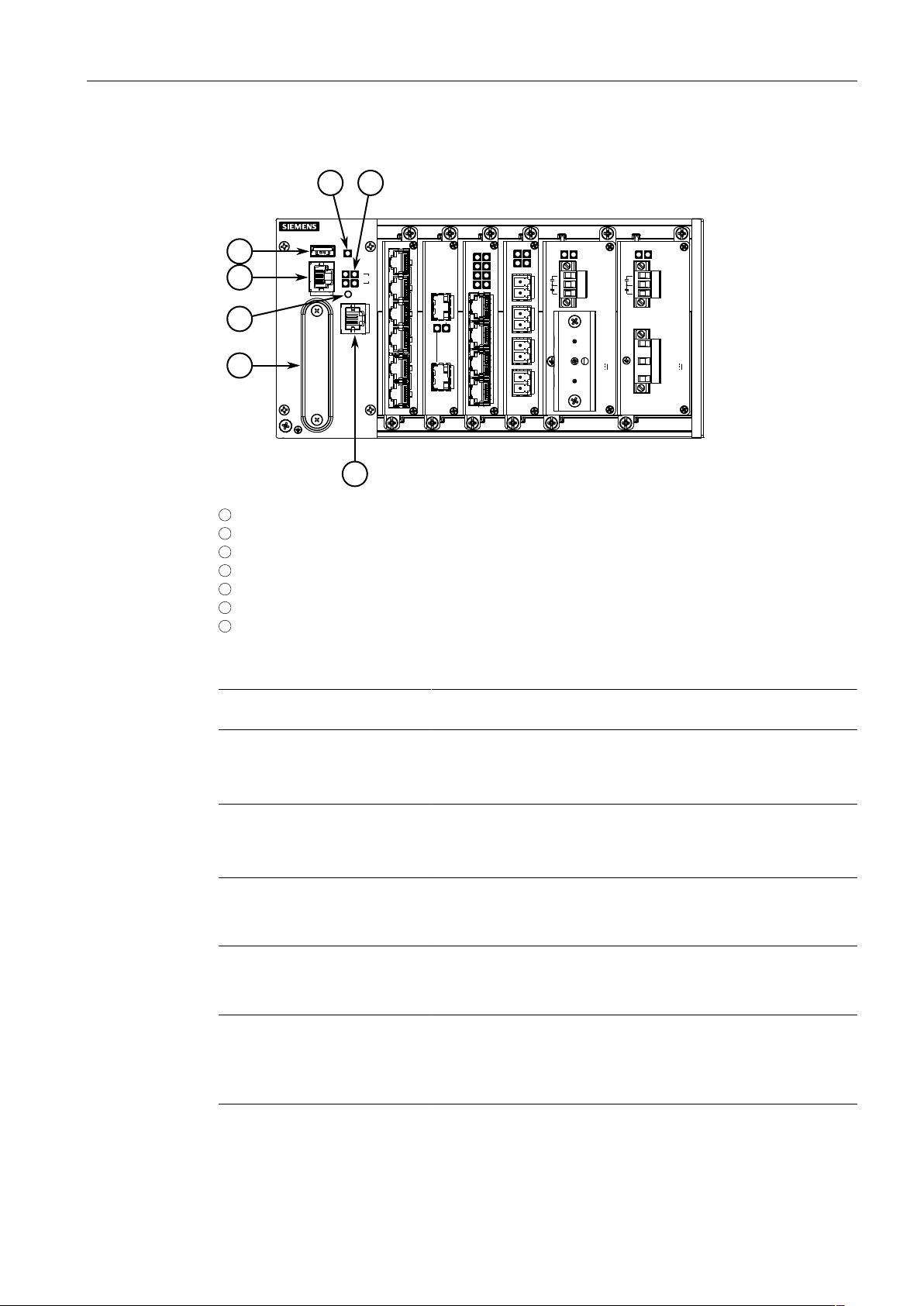
Introduction
4
2
1
3
5 6
7
1.2Description
1
Utility USB Port
2
RS232 Serial Console Port (RJ45)
3
Lamp Test/Alarm Cut-Off (LT/ACO) Button
4
Compact Flash Card Port
5
Alarm Indicator LED
6
Port Status LEDs
7
Management Port
Figure1.1 RUGGEDCOM RX1510
Management Port This 10/100Base-T Ethernet port is used for system management
that is out-of-band from the switch fabric.
RS-232 Serial Console Port The serial console port is for interfacing directly with the device and
accessing initial management functions. For information about connecting to the device via the serial console port, refer to "Connect-
ing to the Device (Page 19)".
Utility USB Port Use the USB port to upgrade the RUGGEDCOM RX1510 software
or install files, such as configuration files and feature key files. For
more information, refer to the RUGGEDCOM RX1510 User Guide
for the RUGGEDCOM RX1510.
Lamp Test/Alarm Cut-Off (LT/
ACO) Button
This button performs two functions:
• Press and hold this button to test all indicator LEDs
• Press and release this button to acknowledge an active alarm
Power Status LEDs Indicates the status of the power modules.
• Green = Power is on
• Off = Power is off
Port Status LEDs Indicates when ports are active.
• Green = OK
• Orange = Warning alert
• Red = Configuration error
Alarm Indicator LED Indicates when an alarm condition exists.
• Green = Alarms cleared/acknowledged
2
Installation Manual, 12/2019, C79000-G8976-1055-16
RUGGEDCOM RX1510
Page 12
• Red = Alarm
Compact Flash Card Port Houses the CompactFlash (CF) card that contains active and back-
up installations of RUGGEDCOM RUGGEDCOM RX1510, along with
the configuration database and other system data. For more information, refer to "Accessing the CompactFlash Card (Page 20)".
1.3 Required Tools and Materials
The following tools and materials are required to install the RUGGEDCOM RX1510:
Tools/Materials Purpose
AC/DC power cord (16 AWG) For connecting power to the device.
Lightning protector For protecting the device from harmful electrical
Shielded coaxial cables For connecting the device to antennas and an Eth-
SIM Card(s) provided by the network carrier For accessing a network carrier's cellular net-
Flathead screwdriver For mounting the device to a DIN rail.
Phillips screwdriver For mounting the device to a panel.
4 x #6-32 screws For mounting the device to a panel.
Braided or equivalent ground wire For grounding the device to safety Earth.
Introduction
1.3Required Tools and Materials
strikes.
ernet network.
work. Required only if a cellular modem module is
equipped.
1.4 Decommissioning and Disposal
Proper decommissioning and disposal of this device is important to prevent malicious
users from obtaining proprietary information and to protect the environment.
Decommissioning
This device may include sensitive, proprietary data. Before taking the device out of
service, either permanently or for maintenance by a third-party, make sure it has
been fully decommissioned.
For more information, refer to the associated User Guide.
Recycling and Disposal
For environmentally friendly recycling and disposal of this device and related accessories, contact a facility certified to dispose of waste electrical and electronic equipment. Recycling and disposal must be done in accordance with local regulations.
RUGGEDCOM RX1510
Installation Manual, 12/2019, C79000-G8976-1055-16
3
Page 13
Introduction
1.5Cabling Recommendations
1.5 Cabling Recommendations
Siemens recommends using SIMATIC NET industrial Ethernet shielded cables for all
Ethernet ports.
1.5.1 Protection On Twisted-Pair Data Ports
All copper Ethernet ports on RUGGEDCOM products include transient suppression
circuitry to protect against damage from electrical transients and conform with IEC
61850-3 and IEEE 1613 Class 1 standards. This means that during a transient electrical event, communications errors or interruptions may occur, but recovery is automatic.
Siemens also does not recommend using copper Ethernet ports to interface with devices in the field across distances that could produce high levels of ground potential
rise (i.e. greater than 2500 V), during line-to-ground fault conditions.
1.5.2 Gigabit Ethernet 1000Base-TX Cabling Recommendations
The IEEE 802.3ab Gigabit Ethernet standard defines 1000 Mbit/s Ethernet communications over distances of up to 100 m (328 ft) using all 4 pairs in category 5 (or
higher) balanced, unshielded twisted-pair cabling. For wiring guidelines, system designers and integrators should refer to the Telecommunications Industry Association
(TIA) TIA/EIA-568-A wiring standard that characterizes minimum cabling performance
specifications required for proper Gigabit Ethernet operation. For reliable, error-free
data communication, new and pre-existing communication paths should be verified
for TIA/EIA-568-A compliance.
The following table summarizes the relevant cabling standards:
Cabling
Category
< 5 No New wiring infrastructure required.
5 Yes Verify TIA/EIA-568-A compliance.
5e Yes
6 Yes No action required.
> 6 Yes Connector and wiring standards to be determined.
Follow these recommendations for copper data cabling in high electrical noise environments:
1000Base-
TX Compliant
Required Action
No action required. New installations should be designed with Category 5e or higher.
• Data cable lengths should be as short as possible, preferably 3 m (10 ft) in
length. Copper data cables should not be used for inter-building communications.
• Power and data cables should not be run in parallel for long distances, and
should be installed in separate conduits. Power and data cables should intersect
at 90° angles when necessary to reduce inductive coupling.
4
Installation Manual, 12/2019, C79000-G8976-1055-16
RUGGEDCOM RX1510
Page 14
Installing the Device
This chapter describes how to install the device, including mounting the device, connecting power, and connecting the device to the network.
DANGER
Electrocution hazard – risk of serious personal injury and/or damage to equipment.
Before performing any maintenance tasks, make sure all power to the device has
been disconnected and wait approximately two minutes for any remaining energy
to dissipate.
WARNING
Radiation hazard – risk of serious personal injury.
This product contains a laser system and is classified as a CLASS 1 LASER PRODUCT.
Use of controls or adjustments or performance of procedures other than those specified herein may result in hazardous radiation exposure.
2
WARNING
Radiation hazard – risk of Radio Frequency (RF) exposure.
This device is compliant with the requirements set forth in FCC 47 CFR, section
1.1307, addressing Radio Frequency (RF) exposure from radio frequency base stations, as defined in FCC OET Bulletin 65 [http://transition.fcc.gov/Bureaus/Engi-
neering_Technology/Documents/bulletins/oet65/oet65.pdf]. The emitted radiation
should be as little as possible. To achieve minimum RF exposure, install the device
when it is configured not to transmit and set it to operational mode remotely, rather
than having a technician enable transmission on-site. For maintenance of the base
station, or other operations which require RF exposure, the exposure should be minimized in time and according to the regulations set forth by the country of installation or the Federal Communications Commission (FCC).
NOTICE
This product contains no user-serviceable parts. Attempted service by unauthorized
personnel shall render all warranties null and void.
Changes or modifications not expressly approved by Siemens AG could invalidate
specifications, test results, and agency approvals, and void the user's authority to
operate the equipment.
RUGGEDCOM RX1510
Installation Manual, 12/2019, C79000-G8976-1055-16
5
Page 15

Installing the Device
2.1General Procedure
NOTICE
This product should be installed in a restricted access location where access can only
be gained by authorized personnel who have been informed of the restrictions and
any precautions that must be taken. Access must only be possible through the use of
a tool, lock and key, or other means of security, and controlled by the authority responsible for the location.
2.1 General Procedure
The general procedure for installing the device is as follows:
NOTICE
The user is responsible for the operating environment of the device, including maintaining the integrity of all protective conductor connections and checking equipment ratings. Make sure to review all operating and installation instructions before
commissioning or performing maintenance on the device.
1. Review the relevant certification information for any regulatory requirements.
For more information, refer to "Approvals (Page 47)".
2. Review the RUGGEDCOM RX1500 Series Modules Catalog for special installation
or regulatory requirements related to the modules installed in the device. In the
case of cellular modem line modules, this includes antenna installation and regulatory requirements.
3. Mount the device.
4. Connect the failsafe alarm relay.
5. Connect power to the device and ground the device to safety Earth.
6. Connect the device to the network.
7. Configure the device.
2.2 Unpacking the Device
When unpacking the device, do the following:
1. Inspect the package for damage before opening it.
2. Visually inspect each item in the package for any physical damage.
3. Verify all items are included.
NOTICE
If any item is missing or damaged, contact Siemens for assistance.
6
Installation Manual, 12/2019, C79000-G8976-1055-16
RUGGEDCOM RX1510
Page 16
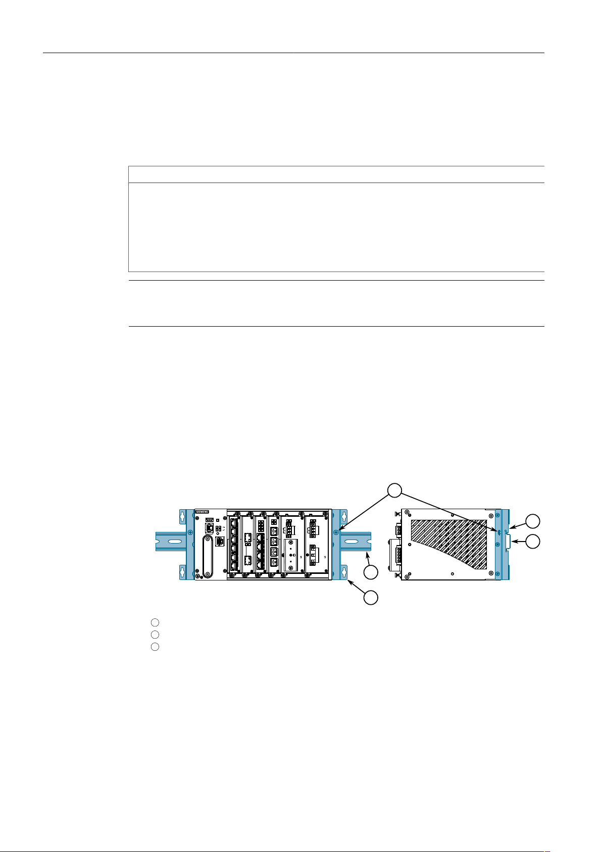
2.3 Mounting the Device
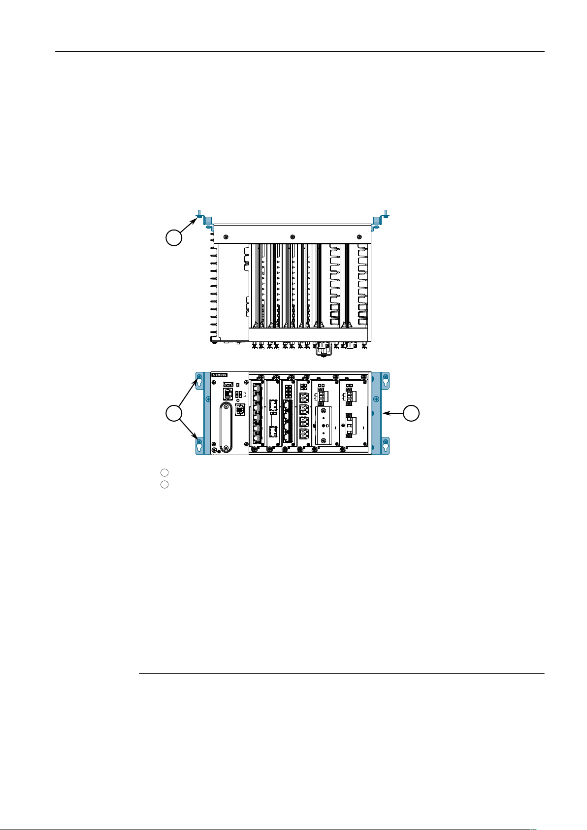
1
2
3
2
1
The RUGGEDCOM RX1510 is designed for maximum mounting and display flexibility.
It can be equipped with connectors that allow it to be installed in a 35 mm (1.4 in)
DIN rail, or directly on a panel.
NOTICE
Heat generated by the device is channeled outwards from the enclosure. As such, it
is recommended that 2.5 cm (1 in) of space be maintained on all open sides of the
device to allow for some convectional airflow.
Forced airflow is not required. However, any increase in airflow will result in a reduction of ambient temperature and improve the long-term reliability of all equipment
mounted in the rack space.
Note
For detailed dimensions of the device with either DIN rail or panel hardware installed,
refer to "Dimension Drawings (Page 44)".
Installing the Device
2.3Mounting the Device
2.3.1 Mounting the Device on a DIN Rail
For DIN rail installations, the RUGGEDCOM RX1510 can be equipped with panel/DIN
rail adapters pre-installed on each side of the chassis. The adapters allow the device
to be slid onto a standard 35 mm (1.4 in) DIN rail.
To mount the device to a DIN rail, do the following:
1. Align the adapters with the DIN rails and slide the device into place.
1
Panel/DIN Rail Adapter
2
DIN Rail
3
Screw
Figure2.1 DIN Rail Mounting
2. Install one of the supplied screws on either side of the device to secure the
adapters to the DIN rails.
RUGGEDCOM RX1510
Installation Manual, 12/2019, C79000-G8976-1055-16
7
Page 17
Installing the Device
1
2
1
2.3.2Mounting the Device to a Panel
2.3.2 Mounting the Device to a Panel
For panel installations, the RUGGEDCOM RX1510 can be equipped with panel/DIN rail
adapters pre-installed on each side of the chassis. The adapters allow the device to
be attached to a panel using screws.
To mount the device to a panel, do the following:
1. Place the device against the panel and mark the mounting holes on the panel.
1
Screw
2
Panel/DIN Rail Adapter
Figure2.2 Panel Mounting
2. Prepare the mounting holes
3. Align the device with the mounting holes and secure it to the panel.
2.4 Connecting the Failsafe Alarm Relay
The failsafe relay can be configured to latch based on alarm conditions. The NO
(Normally Open) contact is closed when the unit is powered and there are no active alarms. If the device is not powered or if an active alarm is configured, the relay
opens the NO contact and closes the NC (Normally Closed) contact.
Note
Control of the failsafe relay output is configurable through RUGGEDCOM RX1510.
One common application for this relay is to signal an alarm if a power failure oc-
8
Installation Manual, 12/2019, C79000-G8976-1055-16
RUGGEDCOM RX1510
Page 18
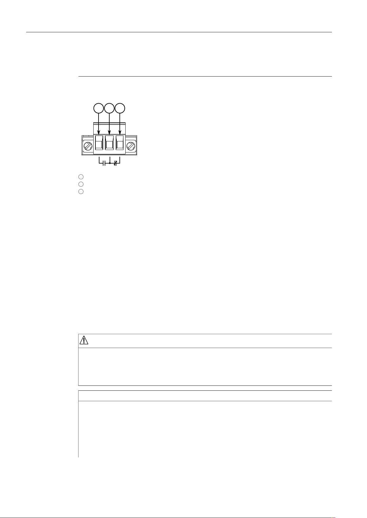
Installing the Device
2 31
2.5Connecting Power
curs. For more information, refer to the RUGGEDCOM RX1510 User Guide for the
RUGGEDCOM RX1510.
The following shows the proper relay connections.
1
Normally Open
2
Common
3
Normally Closed
Figure2.3 Failsafe Alarm Relay Wiring
2.5 Connecting Power
The RUGGEDCOM RX1510 supports dual redundant high AC, high DC and/or low DC
power modules that can be installed in any combination. The use of two power modules is recommended to provide redundancy and load balancing.
Power modules can be equipped with either a screw or European-style (Euroblock)
terminal block. The screw terminal block is installed using Phillips screws and compression plates, allowing either bare wire connections or crimped terminal lugs. Use
#6 size ring lugs for secure, reliable connections under severe shock or vibration.
For information about installing or removing a power module, refer to "Installing/Re-
moving Power Modules (Page 39)".
DANGER
Electrocution hazard – risk of serious personal injury or death
The device may have two power modules equipped, which may be connected to
separate power sources. Make sure all power sources are off before servicing the
power module terminals.
NOTICE
• In a high AC/DC and low DC (24/48 V) power module arrangement, the placement of the AC and DC power supplies is not slot-dependent. Either power module slot can be used for AC or DC power.
• For maximum redundancy in a dual power module configuration, use two independent power sources.
RUGGEDCOM RX1510
Installation Manual, 12/2019, C79000-G8976-1055-16
• Use minimum #16 gage copper wiring when connecting terminal blocks.
9
Page 19
Installing the Device
2.5.1Connecting High AC/DC Power
• The maximum wire length between the terminal block and power source must
not exceed 6 m (20 ft) for 24 V power supplies or 18 m (60 ft) for 48 V power
supplies.
• For 125/230 VAC rated equipment, an appropriately rated AC circuit breaker
must be installed.
• For 125/250 VDC rated equipment, an appropriately rated DC circuit breaker
must be installed.
• It is recommended to provide a 20 A circuit breaker for the power module.
• Equipment must be installed according to applicable local wiring codes and
standards.
2.5.1 Connecting High AC/DC Power
To connect a high AC/DC power supply to the device, do the following:
DANGER
Electrocution hazard – risk of death, serious personal injury and/or damage to
the device
Make sure the supplied cover is always installed over high voltage screw terminal
blocks.
CAUTION
Electrical hazard – risk of damage to equipment
Do not connect AC power cables to a 12, 24 or 48 VDC power supply terminal block.
Damage to the power supply may occur.
Note
The screw terminal block is installed using Phillips screws and compression plates, allowing either bare wire connections or crimped terminal lugs. Use #6 size ring lugs
for secure, reliable connections.
10
Installation Manual, 12/2019, C79000-G8976-1055-16
RUGGEDCOM RX1510
Page 20

2.5.1Connecting High AC/DC Power
4
11
3
2
3
4
5
6
5
2
1
4
1
6
1. Connect the power supply terminal block to the device.
Installing the Device
1
European-style (Euroblock) Terminal Block
2
Positive/Live (+/L) Terminal
3
Ground Terminal
4
Negative/Neutral (-/N) Terminal
Figure2.4 AC Terminal Block Wiring – European-style (Euroblock) Terminal Block for HIP
Power Supplies
1
Not Connected
2
Removable Screw Terminal Block
3
Non-removable Screw Terminal Block
4
Positive/Live (+/L) Terminal
5
Ground Terminal
6
Negative/Neutral (-/N) Terminal
RUGGEDCOM RX1510
Installation Manual, 12/2019, C79000-G8976-1055-16
Figure2.5 AC Terminal Block Wiring – Screw Terminal Block for HI Power Supplies
11
Page 21

Installing the Device
4
3
2
1
2.5.1Connecting High AC/DC Power
2. Connect the positive wire from the power source to the positive/live (+/L) terminal on the terminal block.
3. Connect the negative wire from the power source to the neutral/negative (-/N)
terminal on the terminal block.
4. For screw terminal blocks, install the safety cover.
12
1
Screw
2
Safety Cover
3
Screw Terminal Block
4
RUGGEDCOM RX1510 Device
Figure2.6 Assembling the Safety Cover
5. Using a braided wire or other appropriate grounding wire, connect the ground
terminal to the chassis ground connection.
Installation Manual, 12/2019, C79000-G8976-1055-16
RUGGEDCOM RX1510
Page 22

Installing the Device
3
2
1
4
2.5.2Connecting Low DC Power
6. Using a #10 ring lug and #10-32 screw, secure the ground terminal on the power source to the ground connection on the device. Make sure the lug is tightened to 1.1 N·m (9.5 lbf·in).
1
#10 Ring Lug
2
#10-32 Screw
3
Connection from External Power Source
4
Ground Connection
Figure2.7 Ground Connection
7. Install the safety cover over the terminal block.
2.5.2 Connecting Low DC Power
To connect a low DC power supply to the device, do the following:
CAUTION
Electrical hazard – risk of damage to equipment
Do not connect AC power cables to a 12, 24 or 48 VDC power supply terminal block.
Damage to the power supply may occur.
Note
The RUGGEDCOM RX1510 works with both positive VDC power supplies and negative
VDC power supplies.
Note
The screw terminal block is installed using Phillips screws and compression plates, allowing either bare wire connections or crimped terminal lugs. Use #6 size ring lugs
for secure, reliable connections.
RUGGEDCOM RX1510
Installation Manual, 12/2019, C79000-G8976-1055-16
13
Page 23

Installing the Device
4
1
3
2
1
5
1
2
3
4
5
6
4
6
2.5.2Connecting Low DC Power
1. Connect the power supply terminal block to the device.
1
European-style (Euroblock) Terminal Block
2
Positive (+) Terminal
3
Negative (-) Terminal
4
Ground Terminal
Figure2.8 DC Terminal Block Wiring – European-style (Euroblock) Terminal Block for 12P,
24P and 48P Power Supplies
14
1
Not Connected
2
Removable Screw Terminal Block
3
Non-removable Screw Terminal Block
4
Positive (+) Terminal
5
Negative (-) Terminal
6
Ground Terminal
Installation Manual, 12/2019, C79000-G8976-1055-16
RUGGEDCOM RX1510
Page 24

Installing the Device
4
1
3
2
5
2
3
4
5
6
1
4
1
6
2.5.2Connecting Low DC Power
Figure2.9 DC Terminal Block Wiring – Screw Terminal Block for 12P, 24P and 48P Power
Supplies
1
Not Connected
2
European-style (Euroblock) Terminal Block
3
Positive (+) Terminal
4
Negative (-) Terminal
5
Ground Terminal
Figure2.10 DC Terminal Block Wiring – European-style (Euroblock) Terminal Block for
-12P, -24P and -48P Power Supplies
1
Not Connected
2
Removable Screw Terminal Block
3
RUGGEDCOM RX1510
Installation Manual, 12/2019, C79000-G8976-1055-16
Non-removable Screw Terminal Block
4
Positive (+) Terminal
5
Negative (-) Terminal
15
Page 25

Installing the Device
4
3
2
1
2.5.2Connecting Low DC Power
6
Ground Terminal
Figure2.11 DC Terminal Block Wiring – Screw Terminal Block for -12P, -24P and -48P Pow-
2. Connect the positive wire from the power source to the positive (+) terminal on
the terminal block.
3. Connect the negative wire from the power source to the negative (-) terminal on
the terminal block.
4. For screw terminal blocks, install the safety cover.
er Supplies
16
1
Screw
2
Safety Cover
3
Screw Terminal Block
4
RUGGEDCOM RX1510 Device
Figure2.12 Assembling the Safety Cover
Installation Manual, 12/2019, C79000-G8976-1055-16
RUGGEDCOM RX1510
Page 26

Installing the Device
3
2
1
4
2.5.2Connecting Low DC Power
5. Using a #10 ring lug and #10-32 screw, secure the ground terminal on the power source to the ground connection on the device. Make sure the lug is tightened to 1.1 N·m (9.5 lbf·in).
1
#10 Ring Lug
2
#10-32 Screw
3
Connection from External Power Source
4
Ground Connection
Figure2.13 Ground Connection
6. Install the safety cover over the terminal block. This is mandatory for 48 VDC
and -48 VDC power supplies.
RUGGEDCOM RX1510
Installation Manual, 12/2019, C79000-G8976-1055-16
17
Page 27

Installing the Device
2.5.2Connecting Low DC Power
18
Installation Manual, 12/2019, C79000-G8976-1055-16
RUGGEDCOM RX1510
Page 28

Device Management
1
8
This section describes how to connect to and manage the device.
3.1 Connecting to the Device
The following describes the various methods for accessing the RUGGEDCOM RX1510
console and Web interfaces on the device. For more detailed instructions, refer to the
RUGGEDCOM ROX User Guide for the RUGGEDCOM RX1510.
Serial Console and Management Ports
Connect a workstation directly to the serial console or management ports to access
the boot-time control and RUGGEDCOM RX1510 interfaces. The serial console port
provides access to RUGGEDCOM RX1510's console interface, while the management
port provides access to RUGGEDCOM RX1510's console and Web interfaces.
NOTICE
The serial console and management (MGMT) ports are intended to be used only as
temporary connections during initial configuration or troubleshooting.
3
Connection to the console port is made using an RJ-45-to-DB9 console cable. The following is the pin-out for the console port:
Figure3.1 RJ-45 Console Port Pin Config-
uration
a
The DSR, DCD and DTR pins are connected together internally.
b
The CTS and RTS pins are connected together internally.
c
RI is not connected.
Pin
RJ-45
Male
1 6 DSR
2 1 Reserved (Do Not Connect)
3 4 DTR
4 5 GND Signal Ground
5 2 RxD Receive Da-
6 3 TxD Transmit Da-
7 8 CTS
8 7 RTS
9 RI
DB9
Female
Name Description
a
Data Set Ready
a
b
b
c
>Data Ter-
minal Ready
ta (to DTE)
ta (from DTE)
Clear to Send
>Read to Send
Ring Indicator
RUGGEDCOM RX1510
Installation Manual, 12/2019, C79000-G8976-1055-16
19
Page 29

Device Management
1
8
3.2Configuring the Device
For information about how to connect to the device via the serial console port, refer
to the RUGGEDCOM ROX CLI User Guide for the RUGGEDCOM RX1510.
For information about how to connect to the device via the management port, refer
to either the RUGGEDCOM ROX Web Interface User Guide or the RUGGEDCOM ROX
CLI User Guide for the RUGGEDCOM RX1510.
The management port is a 10/100Base-TX copper Ethernet port with an RJ-45 connector. The following is the pin-out for the management port:
Figure3.2 RJ-45 Management Port
Pin Name Description
1 RX+ Receive Data+
2 RX- Receive Data3 TX+ Transmit Data+
4 Reserved (Do Not Connect)
5 Reserved (Do Not Connect)
6 TX- Transmit Data7 Reserved (Do Not Connect)
8 Reserved (Do Not Connect)
Communication Ports
Connect any of the available Ethernet ports on the device to a management switch
and access the RUGGEDCOM RX1510 console and Web interfaces via the device's
IP address. The factory default IP address for the RUGGEDCOM RX1510 is https://-
192.168.0.2.
For more information about available ports, refer to "Modules (Page 25)".
Note
Single-mode fiber ports only support Ultra Physical Contact (UPC) cable connectors.
3.2 Configuring the Device
Once the device is installed and connected to the network, it must be configured. All
configuration management is done via the RUGGEDCOM RX1510 interface. For more
information about configuring the device, refer to the RUGGEDCOM RX1510 User
Guide associated with the installed software release.
3.3 Accessing the CompactFlash Card
The RUGGEDCOM RX1510 features a removable CompactFlash (CF) card that stores
configuration files, firmware (active and backup versions), file-based feature keys
and other system files.
20
Installation Manual, 12/2019, C79000-G8976-1055-16
RUGGEDCOM RX1510
Page 30

Device Management
3.3Accessing the CompactFlash Card
CAUTION
Configuration hazard – risk of data corruption/loss. Do not remove or insert the CF
card when the device is powered on.
The CF card should only be removed in the following scenarios:
• The chassis is defective (with the exception of power and media modules)
• The CF card is deemed defective or corrupt
• The device is rendered non-functional due to a serious configuration error, data
corruption, or hardware fault
CAUTION
Configuration hazard – risk of data corruption/loss. The following will void the warranty and potentially result in configuration data corruption/loss:
• Using a CF card not approved by Siemens for use with this device
• Removing the CF card in any scenario other than those described in this section
Inserting the CF card
To insert the CF card into the device, do the following:
NOTICE
The device should only be powered on when the CF card is present.
1. Make sure the device is powered down.
2. Remove the CF card access panel.
RUGGEDCOM RX1510
Installation Manual, 12/2019, C79000-G8976-1055-16
21
Page 31

Device Management
2
3
1
3.3Accessing the CompactFlash Card
3. Insert the CF card into the slot until it is fully seated.
1
2
4. Secure the CF card access panel to the chassis.
Removing the CF card
To remove the CF card from the device, do the following:
1. Make sure the device is powered down.
CompactFlash Card
Access Panel
Figure3.3 Inserting the CF Card
22
Installation Manual, 12/2019, C79000-G8976-1055-16
RUGGEDCOM RX1510
Page 32

2. Remove the CF card access panel.
2
3
1
Device Management
3.3Accessing the CompactFlash Card
1
Ejector Button
2
CompactFlash Card
3
Access Panel
Figure3.4 Removing the CF Card
3. Press the ejector button to the left of the CF card and then pull the card out.
4. Secure the CF card access panel to the chassis.
RUGGEDCOM RX1510
Installation Manual, 12/2019, C79000-G8976-1055-16
23
Page 33

Device Management
3.3Accessing the CompactFlash Card
24
Installation Manual, 12/2019, C79000-G8976-1055-16
RUGGEDCOM RX1510
Page 34

Modules
4321
4
The RUGGEDCOM RX1510 features slots for up to two field-replaceable line modules,
which can be used to expand and customize the capabilities of the device to suit specific applications. A variety of modules are available, each featuring a specific type of
communication port: copper Ethernet, fiber optic Ethernet, SFP, WAN, cellular modem and DDS. The RUGGEDCOM APE (Application Processing Engine) line module,
a utility-grade computing platform for running third-party applications directly from
within the RUGGEDCOM RX1510, is also available.
Modules can be installed in any one of the available slots in the device chassis.
Use the RUGGEDCOM RX1510 software to determine which ports are equipped on
the device. For more information, refer to the RUGGEDCOM RX1510 User Guide for
the device.
Note
Only one T1/E1 WAN module and up to two DDS modules are supported.
1
Slot 1
2
Slot 2
3
Slot 3
4
Slot 4
Figure4.1 Available Chassis Slots
RUGGEDCOM RX1510
Installation Manual, 12/2019, C79000-G8976-1055-16
25
Page 35

Modules
4.1Available Modules
4.1 Available Modules
The following is a list of all power and line modules available for use in the RUGGEDCOM RX1510. For more information about individual modules, refer to the
RUGGEDCOM RX1500 Series Modules Catalog [https://support.industry.siemens.com/cs/ca/en/view/109747072].
Power Supply Modules
RUGGEDCOM RX1500PN PS 12 Specifications
Input Range: 9 to 15
VDC
Terminal Type: Removable Screw
RUGGEDCOM RX1500PN PS 12P Specifications
Input Range: 9 to 15
VDC
Terminal Type: European-style (Euroblock)
RUGGEDCOM RX1500PN PS 24 Specifications
Input Range: 13 to 36
VDC
Terminal Type: Removable Screw
Article Numbers
6GK6015-0AL17-0AA0
(Standard)
6GK6015-0AL17-0AA1
(Conformal Coated)
Article Numbers
6GK6015-0AL18-0AA0
(Standard)
6GK6015-0AL18-0AA1
(Conformal Coated)
Article Numbers
6GK6015-0AL11-0AA0
(Standard)
6GK6015-0AL11-0AA1
(Conformal Coated)
26
RUGGEDCOM RX1500PN PS 24P Specifications
Input Range: 13 to 36
VDC
Terminal Type: European-style (Euroblock)
RUGGEDCOM RX1500PN PS 48 Specifications
Input Range: 36 to 72
VDC
Terminal Type: Removable Screw
RUGGEDCOM RX1500PN PS 48P Specifications Article Numbers
Installation Manual, 12/2019, C79000-G8976-1055-16
Article Numbers
6GK6015-0AL14-0AA0
(Standard)
6GK6015-0AL14-0AA1
(Conformal Coated)
Article Numbers
6GK6015-0AL12-0AA0
(Standard)
6GK6015-0AL12-0AA1
(Conformal Coated)
RUGGEDCOM RX1510
Page 36

Modules
4.1Available Modules
Input Range: 36 to 72
VDC
Terminal Type: European-style (Euroblock)
RUGGEDCOM RX1500PN PS HI Specifications
Input Range: 88 to 300
VDC or 85 to 264 VAC
Terminal Type: Removable Screw
RUGGEDCOM RX1500PN PS HIP Specifications
Input Range: 88 to 300
VDC or 85 to 264 VAC
Terminal Type: European-style (Euroblock)
6GK6015-0AL15-0AA0
(Standard)
6GK6015-0AL15-0AA1
(Conformal Coated)
Article Numbers
6GK6015-0AL13-0AA0
(Standard)
6GK6015-0AL13-0AA1
(Conformal Coated)
Article Numbers
6GK6015-0AL16-0AA0
(Standard)
6GK6015-0AL16-0AA1
(Conformal Coated)
Copper Ethernet Modules
RUGGEDCOM RX1500PN LM CG01 Specifications
RUGGEDCOM RX1500PN LM CG03 Specifications
RUGGEDCOM RX1500PN LM CG03B Specifications
Ports: 2
Speed: 1000 Mbps
Interface: TX
Port Type: RJ45
Distance: 100 m (328 ft)
Power Consumption: 4
W
Ports: 2
Speed: 1000 Mbps
Interface: TX
Port Type: M12 (8-Pin,
A-Coded)
Distance: 100 m (328 ft)
Power Consumption: 4
W
Ports: 2
Speed: 1000 Mbps
Interface: TX
Article Numbers
6GK6015-0AL20-0FC0
(Standard)
6GK6015-0AL20-0FC1
(Conformal Coated)
Article Numbers
6GK6015-0AL20-0PB0
(Standard)
6GK6015-0AL20-0PB1
(Conformal Coated)
Article Numbers
6GK6015-0AL20-0PE0
(Standard)
6GK6015-0AL20-0PE1
(Conformal Coated)
RUGGEDCOM RX1510
Installation Manual, 12/2019, C79000-G8976-1055-16
27
Page 37

Modules
4.1Available Modules
RUGGEDCOM RX1500PN LM X CG04 Specifications
RUGGEDCOM RX1500PN LM X CG04B Specifications
RUGGEDCOM RX1500PN LM 4TX03 Specifications
RUGGEDCOM RX1500PN LM 4TX03B Specifications
RUGGEDCOM RX1500PN LM 4TX04 Specifications
Port Type: M12 (8-Pin,
A-Coded, Controlled Bypass)
Distance: 100 m (328 ft)
Power Consumption: 4
W
Ports: 2
Speed: 1000 Mbps
Interface: TX
Port Type: M12 (8-pin,
X-Coded)
Distance: 100 m (328 ft)
Power Consumption: 4
W
Ports: 2
Speed: 1000 Mbps
Interface: TX
Port Type: M12 (8-pin,
X-Coded, Controlled Bypass)
Distance: 100 m (328 ft)
Power Consumption: 4
W
Ports: 4
Speed: 100 Mbps
Interface: TX
Port Type: M12 (4-Pin,
A-Coded)
Distance: 100 m (328 ft)
Power Consumption: 5
W
Ports: 4
Speed: 100 Mbps
Interface: TX
Port Type: M12 (8-Pin,
A-Coded, Controlled Bypass)
Distance: 100 m (328 ft)
Power Consumption: 5
W
Ports: 4
Article Numbers
6GK6015-0AL20-0PH0
(Standard)
6GK6015-0AL20-0PH1
(Conformal Coated)
Article Numbers
6GK6015-0AL20-0PJ0
(Standard)
6GK6015-0AL20-0PJ1
(Conformal Coated)
Article Numbers
6GK6015-0AL20-0PC0
(Standard)
6GK6015-0AL20-0PC1
(Conformal Coated)
Article Numbers
6GK6015-0AL20-0PF0
(Standard)
6GK6015-0AL20-0PF1
(Conformal Coated)
Article Numbers
6GK6015-0AL20-0PD0
(Standard)
28
Installation Manual, 12/2019, C79000-G8976-1055-16
RUGGEDCOM RX1510
Page 38

Modules
4.1Available Modules
Speed: 100 Mbps
Interface: TX
Port Type: M12 (4-Pin,
D-Coded)
Distance: 100 m (328 ft)
Power Consumption: 5
W
RUGGEDCOM RX1500PN LM 4TX04B Specifications
Ports: 4
Speed: 100 Mbps
Interface: TX
Port Type: M12 (4-Pin,
A-Coded, Controlled Bypass)
Distance: 100 m (328 ft)
Power Consumption: 5
W
RUGGEDCOM RX1500PN LM 6TX01 Specifications
Ports: 6
Speed: 100 Mbps
Interface: TX
Port Type: RJ45
Distance: 100 m (328 ft)
Power Consumption: 5
W
6GK6015-0AL20-0PD1
(Conformal Coated)
Article Numbers
6GK6015-0AL20-0PG0
(Standard)
6GK6015-0AL20-0PG1
(Conformal Coated)
Article Numbers
6GK6015-0AL20-0NB0
(Standard)
6GK6015-0AL20-0NB1
(Conformal Coated)
Fiber Optic Ethernet Modules
RUGGEDCOM RX1500PN LM 4FX11 Specifications
RUGGEDCOM RX1500PN LM FL01 Specifications
Mode: MM
Speed: 100 Mbps
Interface: FX
Wavelength: 1300 nm
Ports: 4
Port Type: LC
Distance: 2 km (1.2 mi)
Power Consumption: 5
W
Mode: MM
Speed: 10/100 Mbps
Interface: FL/SX
Wavelength: 820 nm
Ports: 3
Port Type: ST
Article Numbers
6GK6015-0AL20-0BC0
(Standard)
6GK6015-0AL20-0BC1
(Conformal Coated)
Article Numbers
6GK6015-0AL20-0BD0
(Standard)
6GK6015-0AL20-0BD1
(Conformal Coated)
RUGGEDCOM RX1510
Installation Manual, 12/2019, C79000-G8976-1055-16
29
Page 39

Modules
4.1Available Modules
RUGGEDCOM RX1500PN LM FG03 Specifications
RUGGEDCOM RX1500PN LM FG50 Specifications
RUGGEDCOM RX1500PN LM FX50 Specifications
RUGGEDCOM RX1500PN LM 6FX50 Specifications
Distance: 2 km (1.2 mi)
Power Consumption: 5
W
Mode: SM
Speed: 1000 Mbps
Interface: LX
Wavelength: 820 nm
Ports: 4
Port Type: LC
Distance: 10 km (6.2
mi)
Power Consumption: 5
W
SFP Sockets: 2
Speed: 1000 Mbps
Power Consumption: 7
W
SFP Sockets: 4
Speed: 100 Mbps
Power Consumption: 5
W
SFP Sockets: 6
Speed: 100 Mbps
Power Consumption: 7
W
Article Numbers
6GK6015-0AL20-0EC0
(Standard)
6GK6015-0AL20-0EC1
(Conformal Coated)
Article Numbers
6GK6015-0AL20-0JB0
(Standard)
6GK6015-0AL20-0JB1
(Conformal Coated)
Article Numbers
6GK6015-0AL20-0JC0
(Standard)
6GK6015-0AL20-0JC1
(Conformal Coated)
Article Numbers
6GK6015-0AL20-0JD0
(Standard)
6GK6015-0AL20-0JD1
(Conformal Coated)
WAN Modules
30
RUGGEDCOM RX1500PN LM S01 Specifications
Standard: RS232/RS422/
RS485
Ports: 6
Port Type: RJ45
Power Consumption: 3
W
RUGGEDCOM RX1500PN LM TC1 Specifications
Interface: T1/E1
Ports: 1
Port Type: RJ48C
Power Consumption: 3
W
Article Numbers
6GK6015-0AL20-0KB0
(Standard)
6GK6015-0AL20-0KB1
(Conformal Coated)
Article Numbers
6GK6015-0AL20-0MB0
(Standard)
6GK6015-0AL20-0MB1
(Conformal Coated)
Installation Manual, 12/2019, C79000-G8976-1055-16
RUGGEDCOM RX1510
Page 40

Modules
4.1Available Modules
RUGGEDCOM RX1500PN LM TC2 Specifications
Interface: T1/E1
Ports: 2
Port Type: RJ48C
Power Consumption: 3
W
RUGGEDCOM RX1500PN LM TC4 Specifications
Interface: T1/E1
Ports: 4
Port Type: RJ48C
Power Consumption: 3
W
RUGGEDCOM RX1500PN LM E02 Specifications
Interface: E1
Ports: 2
Port Type: BNC (75 Ω)
Power Consumption: 3
W
RUGGEDCOM RX1500PN LM D02 Specifications
Speed: 56 kbps (Master/Slave) or 64 kbps
(Slave)
Ports: 1
Port Type: RJ48S
Power Consumption: 3
W
Article Numbers
6GK6015-0AL20-0MC0
(Standard)
6GK6015-0AL20-0MC1
(Conformal Coated)
Article Numbers
6GK6015-0AL20-0MD0
(Standard)
6GK6015-0AL20-0MD1
(Conformal Coated)
Article Numbers
6GK6015-0AL20-0HC0
(Standard)
6GK6015-0AL20-0HC1
(Conformal Coated)
Article Numbers
6GK6015-0AL20-0LB0
(Standard)
6GK6015-0AL20-0LB1
(Conformal Coated)
Cellular Modem Modules
RUGGEDCOM RX1500PN LM W11 Specifications
RUGGEDCOM RX1500PN LM W12 Specifications
Services: GSM/EDGE/HSPA+
Region: North America
(AT&T)
Port Type: 50 Ω SMA
Antennas: 1 x GSM/
EDGE/HSPA+, 1 x Receive Diversity (Secondary)
SIM: Dual Mini-SIM
(2FF)
Power Consumption: 7
W
Services: GSM/EDGE/HSPA+
Article Numbers
6GK6015-0AL20-0WB0
(Standard)
6GK6015-0AL20-0WB1
(Conformal Coated)
Article Numbers
6GK6015-0AL20-0WC0
(Standard)
RUGGEDCOM RX1510
Installation Manual, 12/2019, C79000-G8976-1055-16
31
Page 41

Modules
4.1Available Modules
Region: North America (AT&T), European
Union, Australia
Port Type: 50 Ω SMA
Antennas: 2 x GSM/
EDGE/HSPA+, 2 x Receive Diversity (Secondary)
SIM: Dual Mini-SIM
(2FF)
Power Consumption: 7
W
RUGGEDCOM RX1500PN LM W21 Specifications
Services: EVDO Rev A
Region: North America
(Verizon)
Port Type: 50 Ω SMA
Antennas: 1 x EVDO Rev
A, 1 x Receive Diversity
(Secondary)
SIM: Dual Mini-SIM
(2FF)
Power Consumption: 7
W
RUGGEDCOM RX1500PN LM W22 Specifications
Services: EVDO Rev A
Region: North America
(Verizon)
Port Type: 50 Ω SMA
Antennas: 2 x EVDO Rev
A, 2 x Receive Diversity
(Secondary)
SIM: Dual Mini-SIM
(2FF)
Power Consumption: 7
W
RUGGEDCOM RX1500PN LM W32 Specifications
Services: EVDO Rev A
Region: North America
(Verizon)
Port Type: 50 Ω SMA
Antennas: 1 x GSM/
EDGE/HSPA+, 1 x EVDO
Rev A, 2 x Receive Diversity (Secondary)
SIM: Dual Mini-SIM
(2FF)
Power Consumption: 7
W
6GK6015-0AL20-0WC1
(Conformal Coated)
Article Numbers
6GK6015-0AL20-0WD0
(Standard)
6GK6015-0AL20-0WD1
(Conformal Coated)
Article Numbers
6GK6015-0AL20-0WE0
(Standard)
6GK6015-0AL20-0WE1
(Conformal Coated)
Article Numbers
6GK6015-0AL20-0WF0
(Standard)
6GK6015-0AL20-0WF1
(Conformal Coated)
32
Installation Manual, 12/2019, C79000-G8976-1055-16
RUGGEDCOM RX1510
Page 42

Modules
4.1Available Modules
RUGGEDCOM RX1500PN LM W41 Specifications
Services: 4G LTE/HSPA+/HSDPA/HSUPA/DCHSPA+/UMTS/WCDAM/EDGE/GPRS/GSM/
GNSS
Region: European Union
Port Type: 50 Ω SMA
Antennas: 1 x LTE Main,
1 x LTE MIMO, 1 x GPS
SIM: Dual Mini-SIM
(2FF)
Power Consumption: 7
W
RUGGEDCOM RX1500PN LM W51 Specifications
Services: 4G LTE/HSPA+/
HSDPA/HSUPA/DC-HSAP
+/UMTS/WDCAM/EDGE/
GPRS/GSM/CDMA/EVDO/GNSS
Region: North America (AT&T, Rogers, Bell,
Telus)
Port Type: 50 Ω SMA
Antennas: 1 x LTE Main,
1 x LTE MIMO, 1 x GPS
SIM: Dual Mini-SIM
(2FF)
Power Consumption: 7
W
RUGGEDCOM RX1500PN LM W61 Specifications
Services: 4G LTE/HSPA+/
CDMA/EVDO/GPS/GNSS
Region: North America
(Verizon, Sprint)
Port Type: 50 Ω SMA
Antennas: 1 x LTE Main,
1 x LTE MIMO, 1 x GPS
SIM: Dual Mini-SIM
(2FF)
Power Consumption: 7
W
RUGGEDCOM RX1500PN LM W81 Specifications
Services: 4G LTE/HSPA+/
EDGE/GPRS/GSM/UMTS/
GNSS
Region: Asia-Pacific
Port Type: 50 Ω SMA
Article Numbers
6GK6015-0AL20-0WG0
(Standard)
6GK6015-0AL20-0WG1
(Conformal Coated)
Article Numbers
6GK6015-0AL20-0WH0
(Standard)
6GK6015-0AL20-0WH1
(Conformal Coated)
Article Numbers
6GK6015-0AL20-0WJ0
(Standard)
6GK6015-0AL20-0WJ1
(Conformal Coated)
Article Numbers
6GK60150AL200WK0
(Standard)
6GK60150AL200WK1
(Conformal Coated)
RUGGEDCOM RX1510
Installation Manual, 12/2019, C79000-G8976-1055-16
33
Page 43

Modules
4.1Available Modules
RUGGEDCOM APE Modules
Antennas: 1 x LTE Main,
1 x LTE MIMO, 1 x GPS
SIM: Dual Mini-SIM
(2FF)
Power Consumption: 7
W
RUGGEDCOM RX1500PN LM APE1402 Specifications
Operating System: Debian Linux®
Processor: Intel Atom
E660 1.3 GHz, 512 KB
Article Numbers
6GK6015-0AL20-0GB0
(Standard)
6GK6015-0AL20-0GB1
(Conformal Coated)
L2 Cache
RAM: 2 GB DDR2, 800
MHz, 32-bit
Disk: 8 GB SATA, Solid
State
Networking: Realtek
RTL8111, RJ45 Gigabit
Ethernet Interface
USB: 2 x USB 2.0
a
Video: Intel 4108
Graphics Processor, DVID
Power Consumption: 10
W
RUGGEDCOM RX1500PN LM APE1402W7 Specifications
Operating System: Windows® Embedded Standard 7
Processor: Intel Atom
Article Numbers
6GK6015-0AL20-0GC0
(Standard)
6GK6015-0AL20-0GC1
(Conformal Coated)
E660 1.3 GHz, 512 KB
L2 Cache
RAM: 2 GB DDR2, 800
MHz, 32-bit
Disk: 8 GB SATA, Solid
State
Networking: Realtek
RTL8111, RJ45 Gigabit
Ethernet Interface
USB: 2 x USB 2.0
a
Video: Intel 4108
Graphics Processor, DVID
Power Consumption: 10
W
RUGGEDCOM RX1500PN LM APE1404 Specifications Article Numbers
34
Installation Manual, 12/2019, C79000-G8976-1055-16
RUGGEDCOM RX1510
Page 44

Modules
4.1Available Modules
Operating System: Debian Linux®
Processor: Intel Atom
E660T 1.3 GHz, 512 KB
L2 Cache
RAM: 2 GB DDR2, 800
MHz, 32-bit
Disk: 16 GB SATA, Solid
State
Networking: Realtek
RTL8111, RJ45 Gigabit
Ethernet Interface
USB: 2 x USB 2.0
Video: Intel 4108
Graphics Processor, DVID
Power Consumption: 10
W
RUGGEDCOM RX1500PN LM APE1404 ADM Specifications
Operating System:
Debian Linux® and
CROSSBOW ADM
Processor: Intel Atom
E660T 1.3 GHz, 512 KB
L2 Cache
RAM: 2 GB DDR2, 800
MHz, 32-bit
Disk: 16 GB SATA, Solid
State
Networking: Realtek
RTL8111, RJ45 Gigabit
Ethernet Interface
USB: 2 x USB 2.0
Video: Intel 4108
Graphics Processor, DVID
Power Consumption: 10
W
RUGGEDCOM RX1500PN LM APE1404W7 Specifications
Operating System: Windows® Embedded Standard 7
Processor: Intel Atom
E660T 1.3 GHz, 512 KB
L2 Cache
RAM: 2 GB DDR2, 800
MHz, 32-bit
Disk: 16 GB SATA, Solid
State
6GK6015-0AL20-0GD0
(Standard)
6GK6015-0AL20-0GD1
(Conformal Coated)
a
Article Numbers
6GK6015-0AL20-0GG0
(Standard)
6GK6015-0AL20-0GG1
(Conformal Coated)
a
Article Numbers
6GK6015-0AL20-0GE0
(Standard)
6GK6015-0AL20-0GE1
(Conformal Coated)
RUGGEDCOM RX1510
Installation Manual, 12/2019, C79000-G8976-1055-16
35
Page 45

Modules
4.1Available Modules
RUGGEDCOM RX1500PN LM APE1404CKP Specifications
RUGGEDCOM RX1510PN LM APE1808 Specifications
a
Maximum combined USB device power consumption is 500 mA at 5 V.
Networking: Realtek
RTL8111, RJ45 Gigabit
Ethernet Interface
USB: 2 x USB 2.0
a
Video: Intel 4108
Graphics Processor, DVID
Power Consumption: 10
W
Operating System:
Check Point GAiA™ OS
Processor: Intel Atom
E660T 1.3 GHz, 512 KB
L2 Cache
RAM: 2 GB DDR2, 800
MHz, 32-bit
Disk: 16 GB SATA, Solid
State
Networking: Realtek
RTL8111, RJ45 Gigabit
Ethernet Interface
USB: 2 x USB 2.0
a
Video: Intel 4108
Graphics Processor, DVID
Power Consumption: 10
W
Operating System: Debian Linux® or Windows® 10 Enterprise
2019 LTSC
Processor: Intel x5E3940 1.8 GHz, 2 MB L2
Cache
RAM: 8 GB DDR3 ECC,
1600 MHz, 32-bit
Disk: 64 GB, Solid State
Networking: Intel I210,
RJ45 Gigabit Ethernet
Interface
USB: 2 x USB 3.0
Video: Intel HD Graphics
Processor, Display Port
Power Consumption: 16
W
Article Numbers
6GK6015-0AL20-0GF0
(Standard)
6GK6015-0AL20-0GF1
(Conformal Coated)
Article Numbers
• Debian Linux®
6GK6015-0AL20-0GH0
(Standard)
6GK6015-0AL20-0GH1
(Conformal Coated)
• Windows® 10 En-
terprise
6GK6015-0AL20-0GJ0
(Standard)
6GK6015-0AL20-0GJ1
(Conformal Coated)
36
Installation Manual, 12/2019, C79000-G8976-1055-16
RUGGEDCOM RX1510
Page 46

Blank Modules
Modules
4.2Installing/Removing Line Modules
RUGGEDCOM RX1500PN PS XXP Specifications
RUGGEDCOM RX1500PN LM Blank Specifications
4.2 Installing/Removing Line Modules
Upon installing a new line module in the device, all features associated with the
module are available in RUGGEDCOM RX1510. For more information, refer to the
RUGGEDCOM ROX User Guide for the RUGGEDCOM RX1510.
Once a line module is removed, all the features associated with the module are hidden or disabled in RUGGEDCOM RX1510.
—
—
Article Numbers
6GK6015-0AL10-0AA0
(Standard)
6GK6015-0AL10-0AA1
(Conformal Coated)
Article Numbers
6GK6015-0AL20-0AA0
(Standard)
6GK6015-0AL20-0AA1
(Conformal Coated)
When installing more than one line module in the device, make sure the total power
consumption of all line modules does not exceed 41.5 W (i.e. the total power made
available to the modules by the chassis). If the total power consumption exceeds
this value, power fluctuations and irregular shut downs may occur.
For the maximum power consumption of each line module, refer to "Available Mod-
ules (Page 26)".
NOTICE
Only one WAN line module is supported per chassis.
Contamination hazard – risk of equipment damage
Prevent the ingress of water, dirts and other debris that may lead to premature
equipment failure. Always make sure slots are not left empty and open ports are
protected with plugs or covers.
Removing a Module
To remove a line module, do the following:
CAUTION
CAUTION
1. [Optional] If the device is installed in a rack, remove it from the rack.
RUGGEDCOM RX1510
Installation Manual, 12/2019, C79000-G8976-1055-16
37
Page 47

Modules
1
2
3
4.2Installing/Removing Line Modules
2. Loosen the screws that secure the module.
3. Pull the module from the chassis to disconnect it.
4. Install a new module or a blank module (to prevent the ingress of dust and dirt).
5. [Optional] If necessary, install the device in the rack.
Installing a Module
To install a line module, do the following:
1. [Optional] If the device is installed in a rack, remove it from the rack.
2. Remove the current module from the slot.
1
Module
2
Chassis
3
Screw
Figure4.2 Removing a Module
38
Installation Manual, 12/2019, C79000-G8976-1055-16
RUGGEDCOM RX1510
Page 48

3. Insert the new module into the slot.
1
2
3
1
2
1
Module
2
Chassis
3
Screw
Modules
4.3Installing/Removing Power Modules
Figure4.3 Installing a Module
4. Tighten the screws to secure the module.
5. [Optional] If necessary, install the device in the rack.
4.3 Installing/Removing Power Modules
The RUGGEDCOM RX1510 supports dual redundant power supply modules.
1
Slot PS1
2
Slot PS2
RUGGEDCOM RX1510
Installation Manual, 12/2019, C79000-G8976-1055-16
39
Page 49

Modules
2
3
1
4.3Installing/Removing Power Modules
Figure4.4 Power Modules
CAUTION
Contamination hazard – risk of equipment damage
Prevent the ingress of water, dirts and other debris that may lead to premature
equipment failure. Always make sure slots are not left empty.
Note
Power modules are hot swappable. When installing/removing a power module, it is
not necessary to turn off power to the redundant power module.
Removing a Power Module
To remove a power module, do the following:
DANGER
Electrocution hazard – risk of serious personal injury or death
Make sure power to the module is turned off before servicing the power supply terminal.
1. Turn off power to the module.
2. Loosen the screws that secure the module to the chassis until the module can be
removed.
40
1
Chassis
2
Screws
3
Power Supply
Figure4.5 Removing a Power Supply
3. Slide the module out of the chassis.
Installation Manual, 12/2019, C79000-G8976-1055-16
RUGGEDCOM RX1510
Page 50

4. Disconnect the power supply wiring from the terminal block. Alternatively, for
2
3
1
convenience, remove the terminal block with the wiring still connected and set
it aside to be connected later to the new module.
5. Install a new or blank module to prevent the ingress of dust and dirt.
Installing a Power Module
To install a power module, do the following:
1. If equipped, remove the existing module.
2. If applicable, connect the supplied terminal block to the module or connect the
terminal block from the previous module.
3. Confirm or connect the wiring from the power supply to the module. For more
information, refer to "Connecting Power (Page 9)".
4. Insert the module into the empty slot.
Modules
4.3Installing/Removing Power Modules
1
Chassis
2
Screws
3
Power Module
Figure4.6 Installing a Power Module
5. Hand-tighten the screws to secure the power module to the chassis.
6. Turn on power to the device and confirm the module is receiving and supplying
power. This is indicated by the LEDs on the module.
RUGGEDCOM RX1510
Installation Manual, 12/2019, C79000-G8976-1055-16
LED State Description
O Green The module is supplying power
I Green The module is receiving power
41
Page 51

Modules
4.3Installing/Removing Power Modules
42
Installation Manual, 12/2019, C79000-G8976-1055-16
RUGGEDCOM RX1510
Page 52

Technical Specifications
This section provides important technical specifications related to the device.
5.1 Power Supply Specifications
Note
When determining cable lengths, make sure the minimum input voltage for the power supply is provided at the power source.
5
Power Sup-
ply Type
HI
HIP
24
24P
48
48P
12
12P
a
Power consumption varies based on the device configuration.
b
(T) denotes time-delay fuse.
Input Range
Min Max
88 VDC 300 VDC
85 VAC 264 VAC
88 VDC 300 VDC
85 VAC 264 VAC
13 VDC 36 VDC 10 A(T)
36 VDC 72 VDC 3.15 A(T)
9 VDC 15 VDC 12 A 67 W
5.2 Failsafe Relay Specifications
Maximum Switching Voltage Rated Switching Current Isolation
30 VDC 5 A
125 VDC 0.1 Aa, 0.15 A
250 VAC 6.25 A
a
Inductive load R/L = 7 ms
b
Resistive load
Internal
Fuse Rating
3.15 A(T)
3.15 A(T)
b
b
b
b
b
Maximum
Power Con-
sumption
65 W
65 W
63.5 W
60 W
2800 VDC for 1 minute be-
tween coil and contacts
a
Insulation
2800 VDC
for 1 minute
1500 VDC
for 1 minute
1500 VAC or
2121 VDC
for 1 minute
RUGGEDCOM RX1510
Installation Manual, 12/2019, C79000-G8976-1055-16
43
Page 53

Technical Specifications
5.3Operating Environment
5.3 Operating Environment
The RUGGEDCOM RX1510 is rated to operate under the following environmental
conditions.
NOTICE
Temperature limits for select line modules may differ from that which can be withstood by the RUGGEDCOM RX1510. Make sure the selected modules are rated for
the expected environmental conditions before deployment. For more information,
refer to the RUGGEDCOM RX1510 Series Modules Catalog.
Ambient Operating Temperaturea b
Ambient Storage Temperature -40 to 85 °C (-40 to 185 °F)
Ambient Relative Humidity
Maximum Altitude 2000 m (6562 ft)
a
b
c
d
c
Maximum ambient operating temperature is 70 °C (158 °F) when the device is installed along with
Underwriter Laboratories (UL) listed devices.
Measured from a 30 cm (12 in) radius surrounding the center of the enclosure.
Operating temperature may vary based on the limitations of installed SFPs. Refer to the RUGGEDCOM
SFP Transceivers Catalog for SFP temperature ratings.
Non-condensing.
-40 to 85 °C (-40 to 185 °F)
d
5% to 95%
5.4 Mechanical Specifications
Weight Approximately 5.0 kg (11 lb)
Ingress Protection IP30
Enclosure Aluminum
5.5 Dimension Drawings
44
Note
All dimensions are in millimeters, unless otherwise stated.
Installation Manual, 12/2019, C79000-G8976-1055-16
RUGGEDCOM RX1510
Page 54

Technical Specifications
237.74
194.6
122.7
5.5Dimension Drawings
Figure5.1 Overall Dimensions
RUGGEDCOM RX1510
Installation Manual, 12/2019, C79000-G8976-1055-16
45
Page 55

Technical Specifications
286.5
207.5
174.2
276.4
4.1
8.1
152.4
78.2
50.8
96.5
50.8
19.7
151.4
102.9
113.3
162.5
162.5
40.6
151.8
102.9
113.4
5.5Dimension Drawings
Figure5.2 Panel and Din Rail Mount Dimensions
Figure5.3 Line Module Dimensions
Figure5.4 Power Module Dimensions
46
Installation Manual, 12/2019, C79000-G8976-1055-16
RUGGEDCOM RX1510
Page 56

Certification
The RUGGEDCOM RX1510 device has been thoroughly tested to guarantee its conformance with recognized standards and has received approval from recognized regulatory agencies.
Note
Certifications related to individual modules are detailed in the RUGGEDCOM Modules
Catalog for the device available online.
6.1 Approvals
This section details the standards to which the RUGGEDCOM RX1510 complies.
6.1.1 TÜV SÜD
This device is certified by TÜV SÜD to meet the requirements of the following standards:
6
• CAN/CSA-C22.2 NO. 60950-1-07 (R2012)
Information Technology Equipment – Safety – Part 1: General Requirements (BiNational standard, with UL 60950-1)
• UL 60950-1
Information Technology Equipment – Safety – Part 1: General Requirements)
6.1.2 European Union (EU)
This device is declared by Siemens AG to comply with essential requirements and
other relevant provisions of the following EU directives:
• Directive 2014/30/EU
Directive 2014/30/EU of the European Parliament and of the Council of 26 February 2014 on the harmonisation of the laws of the Member States relating to electromagnetic compatibility (recast) Text with EEA relevance
• Directive 2014/35/EU
Directive 2014/35/EU of the European Parliament and of the Council of 26 February 2014 on the harmonisation of the laws of the Member States relating to the
RUGGEDCOM RX1510
Installation Manual, 12/2019, C79000-G8976-1055-16
47
Page 57

Certification
0680
6.1.2European Union (EU)
making available on the market of electrical equipment designed for use within
certain voltage limits Text with EEA relevance
• Directive 2011/65/EU
Directive 2011/65/EU of the European Parliament and of the Council of 8 June
2011 on the restriction of the use of certain hazardous substances in electrical
and electronic equipment Text with EEA relevance
• Directive 1999/5/EC
Directive 1999/5/EC of the European Parliament and of the Council of 9 March
1999 on radio equipment and telecommunications terminal equipment and the
mutual recognition of their conformity
• EN 60950-1
Information Technology Equipment – Safety – Part 1: General Requirements
• EN 61000-3-2
Electromagnetic compatibility (EMC) – Part 3-2: Limits – Limits for harmonic current emissions (equipment input current ≤ 16 A per phase)
• EN 61000-3-3
Electromagnetic compatibility (EMC) – Part 3-3: Limits – Limitation of voltage
changes, voltage fluctuations and flicker in public low-voltage supply systems,
for equipment with rated current ≤16 A per phase and not subject to conditional
connection
• EN 61000-6-2
Electromagnetic Compatibility (EMC) – Part 6-2: Generic Standards – Immunity
for Industrial Environments
• EN 60825-1
Safety of Laser Products – Equipment Classification and Requirements
• EN 50581
Technical Documentation for the Assessment of Electrical and Electronic Products with Respect to the Restriction of Hazardous Substances
• EN 55022
Information Technology Equipment – Radio Disturbance Characteristics – Limits
and Methods of Measurement
The device is marked with a CE marking and notified body number, and can be used
throughout the European community.
48
A copy of the CE Declaration of Conformity is available from Siemens AG. For contact
information, refer to "Contacting Siemens (Page vii)".
Installation Manual, 12/2019, C79000-G8976-1055-16
RUGGEDCOM RX1510
Page 58

6.1.3 FCC
Certification
6.1.3FCC
This device has been tested and found to comply with the limits for a Class A digital
device, pursuant to Part 15 of the FCC Rules. These limits are designed to provide reasonable protection against harmful interference when the equipment is operated in a
commercial environment.
This device generates, uses and can radiate radio frequency energy and, if not installed and used in accordance with the instruction manual, may cause harmful interference to radio communications. Operation of this equipment in a residential area is
likely to cause harmful interference in which case users will be required to correct the
interference at their own expense.
NOTICE
Changes or modifications not expressly approved by the party responsible for compliance could void the user's authority to operate this device.
6.1.4 FDA/CDRH
This device meets the requirements of the following U.S. Food and Drug Administration (FDA) standard:
• Title 21 Code of Federal Regulations (CFR) – Chapter I – Sub-chapter J – Radiological Health
6.1.5 ISED
This device is declared by Siemens AG to meet the requirements of the following
ISED (Innovation Science and Economic Development Canada) standard:
• CAN ICES-3 (A)/NMB-3 (A)
6.1.6 RoHS
This device is declared by Siemens AG to meet the requirements of the following RoHS (Restriction of Hazardous Substances) directives for the restricted use of certain
hazardous substances in electrical and electronic equipment:
• China RoHS 2
Administrative Measure on the Control of Pollution Caused by Electronic Informa-
tion Products
A copy of the Material Declaration is available online at https://support.indus-
try.siemens.com/cs/ww/en/view/109738831.
RUGGEDCOM RX1510
Installation Manual, 12/2019, C79000-G8976-1055-16
49
Page 59

Certification
6.1.7Other Approvals
6.1.7 Other Approvals
This device meets the requirements of the following additional standards:
• IEEE 1613
IEEE Standard Environmental and Testing Requirements for Communications
Networking Devices in Electric Power Substations
• IEC 61000-6-2
Electromagnetic Compatibility (EMC) – Part 6-2: Generic Standards – Immunity
for Industrial Environments
• IEC 61850-3
Communication Networks and Systems in Substations – Part 3: General Requirements
6.2 EMC and Environmental Type Tests
The RUGGEDCOM RX1510 has passed the following Electromagnetic Compatibility
(EMC) and environmental tests.
EMC Type Test for IEC 61850-3
Test Description Test Levels Severity
IEC 61000-4-3 Radiated RFI Enclosure Ports 20 V/m
IEC 61000-4-4 Burst (Fast Transient)
IEC 61000-4-5 Surge
IEC 61000-4-6 Induced (Con-
IEC 61000-4-8 Magnetic Field Enclosure Ports
ducted) RFI
Enclosure Contact ± 8 kVIEC 61000-4-2 ESD
Enclosure Air ± 15 kV
Signal ports ± 4 kV @ 2.5 kHz
DC Power Ports
AC Power Ports
Earth ground ports
Signal ports ± 4 kV Line-to-Ground
DC Power Ports ± 2 kV Line-to-Ground
AC Power Ports ± 4 kV Line-to-Ground
Signal ports
DC Power Ports
AC Power Ports
Earth ground ports
± 4 kV 4
± 2 kV Line-to-Line
± 1 kV Line-to-Line
± 2 kV Line-to-Line
10 V 3
100 A/m, continuous
1000 A/m for 1 s
1000 A/m for 1 s 5
Levels
4
Note
4
3
4
Note
a
a
50
Installation Manual, 12/2019, C79000-G8976-1055-16
RUGGEDCOM RX1510
Page 60

6.2EMC and Environmental Type Tests
Test Description Test Levels Severity
IEC 61000-4-11 Voltage Dips
and Interrupts
IEC 61000-4-12 Damped Oscillatory
cy Voltage
IEC 61000-4-17 Ripple on DC
Power Supply
IEC 61000-4-29 Voltage Dips
and Interrupts
IEC 60255-5
a
Siemens-specified severity levels
Dielectric Strength
HV Impulse
AC Power Ports 30% for 1 period
60% for 50 periods
Signal ports
DC Power Ports
AC Power Ports
Signal portsIEC 61000-4-16 Mains FrequenDC Power Ports
DC Power Ports 10% 3
DC Power Ports 30% for 0.1 s
Signal ports 2 kV (Failsafe Relay output)
DC Power Ports 1.5 kV
AC Power Ports 2 kV
Signal ports 5 kV (Failsafe Relay output)
DC Power Ports
AC Power Ports
2.5 kV common, 1 kV differential mode @1 MHz
30 V Continuous
300 V for 1 s
60% for 0.1 s
100% for 0.05 s
5 kV
Certification
Levels
3
4
EMC Immunity Type Tests for IEEE 1613
Note
The RUGGEDCOM RX1510 meets Class 2 requirements for an all-fiber configuration
and Class 1 requirements for copper ports. Class 1 allows for temporary communication loss, while Class 2 requires error-free and interrupted communications.
Description Test Levels
HV Impulse
Dielectric Strength
Fast Transient
Oscillatory
Radiated RFI Enclosure ports 35 V/m
Signal ports 5 kV (Failsafe Relay Output)
DC Power Ports
AC Power Ports
Signal ports 2 kV
DC Power Ports 1.5 kV
AC Power Ports 2 kV
Signal ports ± 4 kV @ 2.5 kHz
DC Power Ports
AC Power Ports
Earth ground ports
Signal ports 2.5 kV common mode @1MHz
DC Power Ports
AC Power Ports
1 kV differential mode @ 1 MHz
5 kV
± 4 kV
2.5 kV common
RUGGEDCOM RX1510
Installation Manual, 12/2019, C79000-G8976-1055-16
51
Page 61

Certification
6.2EMC and Environmental Type Tests
Environmental Type Tests
Test Description Test Levels Severity
IEC 60068-2-1 Cold Temperature Test Ad -40 °C (-40 °F), 16 Hours
IEC 60068-2-2 Dry Heat Test Bd 85 °C (185 °F), 16 Hours
IEC 60068-2-30 Humidity (Damp
IEC 60255-21-1 Vibration 2 g @ 10-150 Hz Class 2
IEC 60255-21-3 Seismic Method A Level 2
MIL-STD-810G Altitude 12192 m (40000 ft)
Description Test Levels
Enclosure Contact ± 8 kVESD
Enclosure Air ± 15 kV
Test Db 95% (non-condensing),
Heat, Cyclic)
Shock 30 g @ 11 ms Class 2IEC 60255-21-2
Bump 10 g @ 16 ms Class 1
Long Life (Random Vibration) IEC 61373
Shock
55 °C (131 °F), 6 cycles
Category 1 Class B
@ 40 °C, 90 minutes
Levels
52
Installation Manual, 12/2019, C79000-G8976-1055-16
RUGGEDCOM RX1510
Page 62

Further Information
Siemens
https://www.siemens.com
Industry Online Support (service and support)
https://support.industry.siemens.com
Industry Mall
https://mall.industry.siemens.com
Siemens AG
Digital Industry
Process Automation
Postfach 48 48
90026 NÜRNBERG
GERMANY
 Loading...