

Page 1
Preface
RUGGEDCOM RX1501
Installation Guide
Introduction
Installing the Device
Modules
Technical Specifications
Dimension Drawings
Certification
1
2
3
4
5
6
04/2017
RC1054-EN-05
Page 2

RUGGEDCOM RX1501
Installation Guide
Copyright © 2017 Siemens Canada Ltd
All rights reserved. Dissemination or reproduction of this document, or evaluation and communication of its contents, is not authorized
except where expressly permitted. Violations are liable for damages. All rights reserved, particularly for the purposes of patent application or
trademark registration.
This document contains proprietary information, which is protected by copyright. All rights are reserved. No part of this document may be
photocopied, reproduced or translated to another language without the prior written consent of Siemens Canada Ltd.
Disclaimer Of Liability
Siemens has verified the contents of this document against the hardware and/or software described. However, deviations between the product
and the documentation may exist.
Siemens shall not be liable for any errors or omissions contained herein or for consequential damages in connection with the furnishing,
performance, or use of this material.
The information given in this document is reviewed regularly and any necessary corrections will be included in subsequent editions. We
appreciate any suggested improvements. We reserve the right to make technical improvements without notice.
Registered Trademarks
RUGGEDCOM™ and ROS™ are trademarks of Siemens Canada Ltd.
Linux® is the registered trademark of Linus Torvalds in the United States and other countries.
The registered trademark Linux® is used pursuant to a sublicense from LMI, the exclusive licensee of Linus Torvalds, owner of the mark on a
world-wide basis.
Other designations in this manual might be trademarks whose use by third parties for their own purposes would infringe the rights of the
owner.
Security Information
Siemens provides products and solutions with industrial security functions that support the secure operation of plants, machines, equipment
and/or networks. They are important components in a holistic industrial security concept. With this in mind, Siemens' products and solutions
undergo continuous development. Siemens recommends strongly that you regularly check for product updates.
For the secure operation of Siemens products and solutions, it is necessary to take suitable preventive action (e.g. cell protection concept) and
integrate each component into a holistic, state-of-the-art industrial security concept. Third-party products that may be in use should also be
considered. For more information about industrial security, visit http://www.siemens.com/industrialsecurity .
To stay informed about product updates as they occur, sign up for a product-specific newsletter. For more information, visit http://
support.automation.siemens.com .
Warranty
Siemens warrants this product for a period of five (5) years from the date of purchase, conditional upon the return to factory for maintenance
during the warranty term. This product contains no user-serviceable parts. Attempted service by unauthorized personnel shall render all
warranties null and void. The warranties set forth in this article are exclusive and are in lieu of all other warranties, performance guarantees
and conditions whether written or oral, statutory, express or implied (including all warranties and conditions of merchantability and fitness for
a particular purpose, and all warranties and conditions arising from course of dealing or usage or trade). Correction of nonconformities in the
manner and for the period of time provided above shall constitute the Seller’s sole liability and the Customer’s exclusive remedy for defective
or nonconforming goods or services whether claims of the Customer are based in contract (including fundamental breach), in tort (including
negligence and strict liability) or otherwise.
For warranty details, visit www.siemens.com/ruggedcom or contact a Siemens customer service representative.
Contacting Siemens
Address
Siemens Canada Ltd
Telephone
Toll-free: 1 888 264 0006
E-mail
ruggedcom.info.i-ia@siemens.com
ii
Page 3

RUGGEDCOM RX1501
Installation Guide
Industry Sector
300 Applewood Crescent
Concord, Ontario
Canada, L4K 5C7
Tel: +1 905 856 5288
Fax: +1 905 856 1995
Web
www.siemens.com/ruggedcom
iii
Page 4

RUGGEDCOM RX1501
Installation Guide
iv
Page 5

RUGGEDCOM RX1501
Installation Guide
Table of Contents
Table of Contents
Preface ............................................................................................................ vii
Alerts ................................................................................................................................................. vii
Related Documents ............................................................................................................................ viii
Accessing Documentation .................................................................................................................. viii
Training ............................................................................................................................................ viii
Customer Support .............................................................................................................................. viii
Chapter 1
Introduction ..................................................................................................... 1
1.1Feature Highlights ........................................................................................................................ 1
1.2Description ................................................................................................................................... 1
Chapter 2
Installing the Device ......................................................................................... 3
2.1General Procedure ........................................................................................................................ 4
2.2Required Tools and Materials ......................................................................................................... 4
2.3Cabling Recommendations ............................................................................................................ 5
2.3.1Protection On Twisted-Pair Data Ports .................................................................................. 5
2.3.2Gigabit Ethernet 1000Base-TX Cabling Recommendations ..................................................... 5
2.4Mounting the Device .................................................................................................................... 6
2.4.1Mounting the Device to a Rack ........................................................................................... 6
2.4.2Mounting the Device on a DIN Rail ...................................................................................... 7
2.4.3Mounting the Device to a Panel .......................................................................................... 8
2.5Connecting the Failsafe Alarm Relay .............................................................................................. 9
2.6Connecting Power ....................................................................................................................... 10
2.6.1Connecting High AC/DC Power .......................................................................................... 11
2.6.2Connecting Low DC Power ................................................................................................ 13
2.7Connecting to the Device ............................................................................................................ 15
2.8Configuring the Device ................................................................................................................ 16
Chapter 3
Modules .......................................................................................................... 17
3.1Available Modules ....................................................................................................................... 18
3.2Installing/Removing Line Modules ................................................................................................ 25
3.3Installing/Removing Power Modules ............................................................................................. 27
v
Page 6

Table of Contents
Chapter 4
RUGGEDCOM RX1501
Installation Guide
Technical Specifications .................................................................................. 31
4.1Power Supply Specifications ........................................................................................................ 31
4.2Failsafe Relay Specifications ......................................................................................................... 32
4.3Operating Environment ............................................................................................................... 32
4.4Mechanical Specifications ............................................................................................................ 32
Chapter 5
Dimension Drawings ....................................................................................... 33
Chapter 6
Certification .................................................................................................... 37
6.1Approvals ................................................................................................................................... 37
6.1.1 UL ................................................................................................................................... 37
6.1.2TÜV SÜD ......................................................................................................................... 38
6.1.3European Union (EU) ....................................................................................................... 38
6.1.4 FCC ................................................................................................................................. 39
6.1.5FDA/CDRH ........................................................................................................................ 39
6.1.6 ISED ................................................................................................................................ 39
6.1.7 RoHS ............................................................................................................................... 40
6.1.8Other Approvals ............................................................................................................... 40
6.2EMC and Environmental Type Tests .............................................................................................. 40
vi
Page 7
RUGGEDCOM RX1501
Installation Guide
Preface
This guide describes the RUGGEDCOM RUGGEDCOM RX1501. It describes the major features of the device,
installation, commissioning and important technical specifications.
It is intended for use by network technical support personnel who are responsible for the installation,
commissioning and maintenance of the device. It is also recommended for use by network and system planners,
system programmers, and line technicians.
CONTENTS
• “ Alerts ”
• “Related Documents”
• “Accessing Documentation”
• “Training”
• “Customer Support”
Preface
Alerts
The following types of alerts are used when necessary to highlight important information.
DANGER!
DANGER alerts describe imminently hazardous situations that, if not avoided, will result in death or
serious injury.
WARNING!
WARNING alerts describe hazardous situations that, if not avoided, may result in serious injury and/or
equipment damage.
CAUTION!
CAUTION alerts describe hazardous situations that, if not avoided, may result in equipment damage.
IMPORTANT!
IMPORTANT alerts provide important information that should be known before performing a procedure
or step, or using a feature.
NOTE
NOTE alerts provide additional information, such as facts, tips and details.
Alerts vii
Page 8

Preface
RUGGEDCOM RX1501
Installation Guide
Related Documents
Other documents that may be of interest include:
• RUGGEDCOM ROX II User Guide for the RUGGEDCOM RX1501
• RUGGEDCOM RX1500 Series Modules Catalog
Accessing Documentation
The latest user documentation for RUGGEDCOM RX1501 is available online at www.siemens.com/ruggedcom. To
request or inquire about a user document, contact Siemens Customer Support.
Training
Siemens offers a wide range of educational services ranging from in-house training of standard courses on
networking, Ethernet switches and routers, to on-site customized courses tailored to the customer's needs,
experience and application.
Siemens' Educational Services team thrives on providing our customers with the essential practical skills to make
sure users have the right knowledge and expertise to understand the various technologies associated with critical
communications network infrastructure technologies.
Siemens' unique mix of IT/Telecommunications expertise combined with domain knowledge in the utility,
transportation and industrial markets, allows Siemens to provide training specific to the customer's application.
For more information about training services and course availability, visit www.siemens.com/ruggedcom or
contact a Siemens Sales representative.
Customer Support
Customer support is available 24 hours, 7 days a week for all Siemens customers. For technical support or general
information, contact Siemens Customer Support through any of the following methods:
Online
Visit http://www.siemens.com/automation/support-request to submit a Support Request (SR) or check on the status of an
existing SR.
Telephone
Call a local hotline center to submit a Support Request (SR). To locate a local hotline center, visit http://
www.automation.siemens.com/mcms/aspa-db/en/automation-technology/Pages/default.aspx .
Mobile App
Install the Industry Online Support app by Siemens AG on any Android, Apple iOS or Windows mobile device and be able to:
• Access Siemens' extensive library of support documentation, including FAQs and manuals
• Submit SRs or check on the status of an existing SR
• Contact a local Siemens representative from Sales, Technical Support, Training, etc.
• Ask questions or share knowledge with fellow Siemens customers and the support community
viii Related Documents
Page 9

RUGGEDCOM RX1501
Installation Guide
Introduction
The RUGGEDCOM RUGGEDCOM RX1501 is a cost-efficient, rugged Layer 3 switch and router. The RUGGEDCOM
RX1501’s modular and field replaceable platform can be equipped with WAN, serial, and Ethernet options, making
it ideally suited for electric power utilities, the industrial plant floor, and traffic control systems.
The RUGGEDCOM RX1501 is designed to provide a high level of immunity to electromagnetic interference (EMI)
and heavy electrical surges typical of the harsh environments found in many industrial applications. An operating
temperature range of -40 to 85 °C (-40 to 185 °F) allows the RUGGEDCOM RX1501 to be placed in almost any
location.
CONTENTS
• Section1.1, “Feature Highlights”
• Section1.2, “Description”
Chapter 1
Introduction
Section1.1
Feature Highlights
Reliability in Harsh Environments
• Immunity to EMI and high voltage electrical
transients
• -40 to 85 °C (-40 to 185 °F) operating temperature
(no fans)
• Failsafe output relay for critical failure or error
alarming
Universal Power Supply Options
• Single, removable power supply module
• Fully integrated power supply (no external adapter)
• Input voltage ranges: 13-36 VDC and 37-72 VDC
or 85-264 VAC and 88-300 VDC for worldwide
operability
• CSA/UL 60950-1 safety approved to 85 °C (185 °F)
Section1.2
Physical Ports
• Field replaceable line modules
• Up to 36 100Base-FX ports
• Up to 36 10/100Base-TX ports
• Up to 18 10Base-FL/100Base-SX ports
• Up to 4 Gigabit Ethernet ports
• Up to 36 serial ports
• Up to 4 T1/E1 RJ48C ports or 2 E1 BNC ports
• Up to 2 DDS (Digital Data Services) ports
• Up to 8 active cellular data interfaces
Description
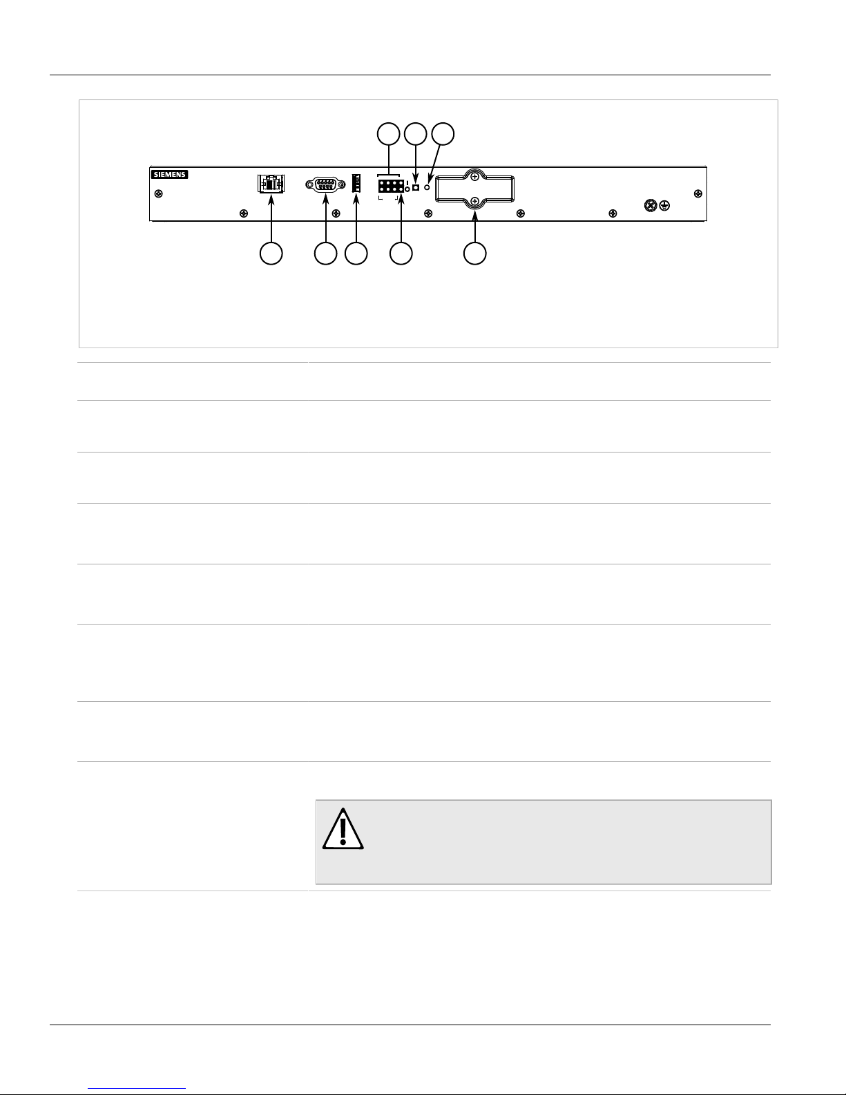
The RUGGEDCOM RX1501 features various ports, controls and indicator LEDs on the front panel for connecting,
configuring and troubleshooting the device.
Feature Highlights 1
Page 10
Chapter 1
1 2 3 8
6 7
4
5
Introduction
Figure1: RUGGEDCOM RX1501
1.Management Port 2.RS232 Serial Console Port (DB9) 3.Utility USB Port 4.Port Status LEDs 5.Power Status LEDs 6.Alarm
Indicator LED 7.Lamp Test/Alarm Cut-Off (LT/ACO) Button 8.Compact Flash Card Port
RUGGEDCOM RX1501
Installation Guide
Management Port This 10/100Base-T Ethernet port is used for system management that is out-of-band from the
RS-232 Serial Console Port The serial console port is for interfacing directly with the device and accessing initial
Utility USB Port Use the USB port to upgrade the ROX II software or install files, such as configuration files
Lamp Test/Alarm Cut-Off (LT/ACO) Button This button performs two functions:
Power Status LEDs Indicates the status of the power modules.
Port Status LEDs Indicates when ports are active.
Alarm Indicator LED Indicates when an alarm condition exists.
Compact Flash Card Port Houses the 1 GB compact flash card that contains active and backup installations of
switch fabric.
management functions. For information about connecting to the device via the serial
console port, refer to Section2.7, “Connecting to the Device” .
and feature key files. For more information, refer to the RUGGEDCOM ROX II User Guide for
the RUGGEDCOM RX1501.
• Press and hold this button to test all indicator LEDs
• Press and release this button to acknowledge an active alarm
• I = The power module is receiving power
• O = The power module is supplying power
• Green = OK
• Orange = Warning alert
• Red = Configuration error
• Green = Alarms cleared/acknowledged
• Red = Alarm
RUGGEDCOM ROX II, along with the configuration database and other system data.
2 Description
CAUTION!
Configuration hazard – risk of data corruption/loss. Do not open the compact
flash card port, unless specifically instructed to by a Siemens Customer Support
representative. The warranty will be void otherwise. Removing the compact
flash card improperly can corrupt configuration data.
Page 11
RUGGEDCOM RX1501
Installation Guide
Installing the Device
This chapter describes how to install the device, including mounting the device, connecting power, and
connecting the device to the network.
DANGER!
Electrocution hazard – risk of serious personal injury and/or damage to equipment. Before performing
any maintenance tasks, make sure all power to the device has been disconnected and wait
approximately two minutes for any remaining energy to dissipate.
WARNING!
Radiation hazard – risk of serious personal injury. This product contains a laser system and is classified
as a CLASS 1 LASER PRODUCT. Use of controls or adjustments or performance of procedures other
than those specified herein may result in hazardous radiation exposure.
Installing the Device
Chapter 2
WARNING!
Radiation hazard – risk of Radio Frequency (RF) exposure. This device is compliant with the
requirements set forth in FCC 47 CFR, section 1.1307, addressing Radio Frequency (RF) exposure from
radio frequency base stations, as defined in FCC OET Bulletin 65 [http://transition.fcc.gov/Bureaus/
Engineering_Technology/Documents/bulletins/oet65/oet65.pdf]. The emitted radiation should be as
little as possible. To achieve minimum RF exposure, install the device when it is configured not to
transmit and set it to operational mode remotely, rather than having a technician enable transmission
on-site. For maintenance of the base station, or other operations which require RF exposure, the
exposure should be minimized in time and according to the regulations set forth by the country of
installation or the Federal Communications Commission (FCC).
IMPORTANT!
This product contains no user-serviceable parts. Attempted service by unauthorized personnel shall
render all warranties null and void.
Changes or modifications not expressly approved by Siemens Canada Ltd could invalidate
specifications, test results, and agency approvals, and void the user's authority to operate the
equipment.
IMPORTANT!
This product should be installed in a restricted access location where access can only be gained by
authorized personnel who have been informed of the restrictions and any precautions that must be
taken. Access must only be possible through the use of a tool, lock and key, or other means of security,
and controlled by the authority responsible for the location.
CONTENTS
• Section2.1, “General Procedure”
• Section2.2, “Required Tools and Materials”
• Section2.3, “Cabling Recommendations”
3
Page 12

Chapter 2
Installing the Device
RUGGEDCOM RX1501
Installation Guide
• Section2.4, “Mounting the Device”
• Section2.5, “Connecting the Failsafe Alarm Relay”
• Section2.6, “Connecting Power”
• Section2.7, “Connecting to the Device”
• Section2.8, “Configuring the Device”
Section2.1
General Procedure
The general procedure for installing the device is as follows:
1. Review the relevant certification information for any regulatory requirements. For more information, refer to
Section6.1, “Approvals” .
2. Review the RUGGEDCOM RX1500 Series Modules Catalog for special installation or regulatory requirements
related to the modules installed in the device. In the case of cellular modem line modules, this includes
antenna installation and regulatory requirements.
3. Mount the device.
4. Connect the failsafe alarm relay.
5. Connect power to the device and ground the device to safety Earth.
6. Connect the device to the network.
7. Configure the device.
Section2.2
Required Tools and Materials
The following tools and materials are required to install the RUGGEDCOM RX1501:
Tools/Materials Purpose
AC/DC power cord (16 AWG) For connecting power to the device.
Lightning protector For protecting the device from harmful electrical strikes.
Shielded coaxial cables For connecting the device to antennas and an Ethernet network.
SIM Card(s) provided by the network carrier For accessing a network carrier's cellular network. Required only if a
Flathead screwdriver For mounting the device to a DIN rail.
Phillips screwdriver For mounting the device to a panel.
cellular modem module is equipped.
4 x #6-32 screws For mounting the device to a panel.
Braided or equivalent ground wire For grounding the device to safety Earth.
4 General Procedure
Page 13

RUGGEDCOM RX1501
Installation Guide
Section2.3
Installing the Device
Cabling Recommendations
Siemens recommends using SIMATIC NET industrial Ethernet shielded cables for all Ethernet ports.
CONTENTS
• Section2.3.1, “Protection On Twisted-Pair Data Ports”
• Section2.3.2, “Gigabit Ethernet 1000Base-TX Cabling Recommendations”
Section2.3.1
Protection On Twisted-Pair Data Ports
All copper Ethernet ports on RUGGEDCOM products include transient suppression circuitry to protect against
damage from electrical transients and conform with IEC 61850-3 and IEEE 1613 Class 1 standards. This means
that during a transient electrical event, communications errors or interruptions may occur, but recovery is
automatic.
Siemens also does not recommend using copper Ethernet ports to interface with devices in the field across
distances that could produce high levels of ground potential rise (i.e. greater than 2500 V), during line-to-ground
fault conditions.
Chapter 2
Section2.3.2
Gigabit Ethernet 1000Base-TX Cabling Recommendations
The IEEE 802.3ab Gigabit Ethernet standard defines 1000 Mbit/s Ethernet communications over distances of up
to 100 m (328 ft) using all 4 pairs in category 5 (or higher) balanced, unshielded twisted-pair cabling. For wiring
guidelines, system designers and integrators should refer to the Telecommunications Industry Association (TIA)
TIA/EIA-568-A wiring standard that characterizes minimum cabling performance specifications required for proper
Gigabit Ethernet operation. For reliable, error-free data communication, new and pre-existing communication
paths should be verified for TIA/EIA-568-A compliance.
The following table summarizes the relevant cabling standards:
Cabling Category
< 5 No New wiring infrastructure required.
5 Yes Verify TIA/EIA-568-A compliance.
5e Yes No action required. New installations should be designed with Category 5e or higher.
6 Yes No action required.
> 6 Yes Connector and wiring standards to be determined.
Follow these recommendations for copper data cabling in high electrical noise environments:
• Data cable lengths should be as short as possible, preferably 3 m (10 ft) in length. Copper data cables should
not be used for inter-building communications.
• Power and data cables should not be run in parallel for long distances, and should be installed in separate
conduits. Power and data cables should intersect at 90° angles when necessary to reduce inductive coupling.
1000Base-
TX Compliant
Required Action
Cabling Recommendations 5
Page 14
Chapter 2
Installing the Device
Section2.4
Mounting the Device
The RUGGEDCOM RX1501 is designed for maximum mounting and display flexibility. It can be equipped with
connectors that allow it to be installed in a 48 cm (19 in) rack, 35 mm (1.4 in) DIN rail or directly on a panel.
IMPORTANT!
Heat generated by the device is channeled outwards to the enclosure. As such, it is recommended that
2.5 cm (1 in) of space be maintained on all open sides of the device to allow for some convectional
airflow.
Forced airflow is not required. However, any increase in airflow will result in a reduction of ambient
temperature and improve the long-term reliability of all equipment mounted in the rack space.
NOTE
For detailed dimensions of the device with either rack, DIN rail or panel hardware installed, refer to
Chapter5, Dimension Drawings .
CONTENTS
• Section2.4.1, “Mounting the Device to a Rack”
RUGGEDCOM RX1501
Installation Guide
• Section2.4.2, “Mounting the Device on a DIN Rail”
• Section2.4.3, “Mounting the Device to a Panel”
Section2.4.1
Mounting the Device to a Rack
For rack mount installations, the RUGGEDCOM RX1501 can be equipped with rack mount adapters pre-installed at
the front or rear of the chassis. Additional adapters are provided for added stability.
CAUTION!
Vibration hazard – risk of damage to the device. Always use four rack mount adapters (two at the front
of the device and two at the rear) when installing the device in high-vibration or seismically active
locations.
CAUTION!
Electrical/mechanical hazard – risk of damage to the device. Before installing the device in a rack,
make sure of the following:
• When installing the device in a closed or multi-device rack, be aware that the operating ambient
temperature of the rack may be higher than the ambient temperature of the room. Make sure the
rack is installed in a suitable environment that can withstand the maximum ambient temperature
generated by the rack.
• Do not exceed the maximum number of devices or weight restrictions specified by the rack
manufacturer.
• Do not overload the supply circuit. Refer to the over-current protection and power supply ratings
specified by the rack manufacturer.
6 Mounting the Device
Page 15
RUGGEDCOM RX1501
3 3
1 2
Installation Guide
• Make sure the rack and all devices have a proper ground-to-Earth connection. Pay particular
attention to power supply connections other than direct connections to the branch circuit (e.g. power
strips).
To secure the device to a standard 48 cm (19 in) rack, do the following:
1. Make sure the rack mount adapters are installed on the correct side of the chassis.
• To make the modules and ports accessible, install the rack mount adapters at the rear of the chassis
• To make the management ports and LEDs accessible, install the rack mount adapters at the front of the
chassis
NOTE
The chassis features multiple mounting holes, allowing the rack mount adapters to be installed up
to 25 mm (1 in) from the face of the device.
Installing the Device
Chapter 2
Figure2:Rack Mount Adapters
1.Rear 2.Front 3.Rack Mount Adapter
2. If required, install adapters on the opposite side of the device to protect from vibrations.
3. Insert the device into the rack.
4. Secure the adapters to the rack using the supplied hardware.
Section2.4.2
Mounting the Device on a DIN Rail
For DIN rail installations, the RUGGEDCOM RX1501 can be equipped with panel/DIN rail adapters pre-installed on
each side of the chassis. The adapters allow the device to be slid onto a standard 35 mm (1.4 in) DIN rail.
To mount the device to a DIN rail, do the following:
1. Align the adapters with the DIN rails and slide the device into place.
Mounting the Device on a DIN Rail 7
Page 16

Chapter 2
3
1
2
2
1
Installing the Device
Figure3:DIN Rail Mounting
1.Panel/DIN Rail Adapter 2.DIN Rail 3.Screw
RUGGEDCOM RX1501
Installation Guide
2. Install one of the supplied screws on either side of the device to secure the adapters to the DIN rails.
Section2.4.3
Mounting the Device to a Panel
For panel installations, the RUGGEDCOM RX1501 can be equipped with panel/DIN rail adapters pre-installed on
each side of the chassis. The adapters allow the device to be attached to a panel using screws.
To mount the device to a panel, do the following:
1. Place the device against the panel and mark the mounting holes on the panel.
8 Mounting the Device to a Panel
Page 17

RUGGEDCOM RX1501
21
1
Installation Guide
Installing the Device
Chapter 2
Figure4:Panel Mounting
1.Screw 2.Panel/DIN Rail Adapter
2. Prepare the mounting holes
3. Align the device with the mounting holes and secure it to the panel.
Section2.5
Connecting the Failsafe Alarm Relay
The failsafe relay can be configured to latch based on alarm conditions. The NO (Normally Open) contact is closed
when the unit is powered and there are no active alarms. If the device is not powered or if an active alarm is
configured, the relay opens the NO contact and closes the NC (Normally Closed) contact.
NOTE
Control of the failsafe relay output is configurable through ROX II. One common application for this
relay is to signal an alarm if a power failure occurs. For more information, refer to the ROX II User
Guide for the RUGGEDCOM RX1501.
The following shows the proper relay connections.
Connecting the Failsafe Alarm Relay 9
Page 18

Chapter 2
2 31
Installing the Device
Figure5:Failsafe Alarm Relay Wiring
1.Normally Open 2.Common 3.Normally Closed
Section2.6
Connecting Power
The RUGGEDCOM RX1501 supports a single high AC, high DC or low DC power module.
RUGGEDCOM RX1501
Installation Guide
Power modules can be equipped with either a screw-type or pluggable terminal block. The screw-type terminal
block is installed using Phillips screws and compression plates, allowing either bare wire connections or crimped
terminal lugs. Use #6 size ring lugs for secure, reliable connections under severe shock or vibration.
For information about installing or removing a power module, refer to Section3.3, “Installing/Removing Power
Modules” .
DANGER!
Electrocution hazard – risk of serious personal injury or death. Make sure the power source is off before
servicing the power supply terminal.
IMPORTANT!
• Use only #16 gage copper wiring when connecting terminal blocks.
• The maximum wire length between the terminal block and power source must not exceed 6 m (20 ft)
for 24 V power supplies or 18 m (60 ft) for 48 V power supplies.
• For 125/230 VAC rated equipment, an appropriately rated AC circuit breaker must be installed.
• For 125/250 VDC rated equipment, an appropriately rated DC circuit breaker must be installed.
• It is recommended to provide a separate 20 A circuit breaker for each power supply module.
• Equipment must be installed according to applicable local wiring codes and standards.
CONTENTS
• Section2.6.1, “Connecting High AC/DC Power”
10 Connecting Power
Page 19

RUGGEDCOM RX1501
1
2
3 4
Installation Guide
• Section2.6.2, “Connecting Low DC Power”
Section2.6.1
Connecting High AC/DC Power
To connect a high AC/DC power supply to the device, do the following:
DANGER!
Electrocution hazard – risk of death, serious personal injury and/or damage to the device. Make sure
the supplied cover is always installed over high voltage screw-type terminal blocks.
CAUTION!
Electrical hazard – risk of damage to equipment. Do not connect AC power cables to a 12, 24 or 48 VDC
power supply terminal block. Damage to the power supply may occur.
NOTE
The screw-type terminal block is installed using Phillips screws and compression plates, allowing either
bare wire connections or crimped terminal lugs. Use #6 size ring lugs for secure, reliable connections.
Installing the Device
Chapter 2
1. Connect the power supply terminal block to the device.
Figure6:AC Terminal Block Wiring – Pluggable Terminal Block for HIP Power Supplies
1.3-Position Terminal Block 2.Positive/Live (+/L) Terminal 3.Ground Terminal 4.Negative/Neutral (-/N) Terminal
Connecting High AC/DC Power 11
Page 20

Chapter 2
2
3
4
5
1
3
4
5
2
1
Installing the Device
Figure7:AC Terminal Block Wiring – Screw-Type Terminal Block for HI Power Supplies
1.5-Position Terminal Block 2.3-Position Terminal Block 3.Positive/Live (+/L) Terminal 4.Ground Terminal 5.Negative/
Neutral (-/N) Terminal
RUGGEDCOM RX1501
Installation Guide
2. Connect the positive wire from the power source to the positive/live (+/L) terminal on the terminal block.
3. Connect the negative wire from the power source to the neutral/negative (-/N) terminal on the terminal block.
4. Using a braided wire or other appropriate grounding wire, connect the ground terminal to the chassis ground
connection. The ground terminal is used as the ground conductor for surge and transient suppression
circuitry internal to the unit.
5. Using a #10 ring lug and #10-32 screw, secure the ground terminal on the power source to the chassis
ground terminal on the device. Make sure the lug is tightened to 3.4 N·m (30 lbf·in).
Figure8:Chassis Ground Connection
1.#10-32 Screw 2.#10 Ring Lug
6. Install the safety cover over the terminal block.
12 Connecting High AC/DC Power
Page 21

RUGGEDCOM RX1501
3
4
21
Installation Guide
Section2.6.2
Connecting Low DC Power
To connect a low DC power supply to the device, do the following:
CAUTION!
Electrical hazard – risk of damage to equipment. Do not connect AC power cables to a 12, 24 or 48 VDC
power supply terminal block. Damage to the power supply may occur.
IMPORTANT!
When connecting the device to a DC power source, make sure the source provides only positive voltage.
NOTE
The screw-type terminal block is installed using Phillips screws and compression plates, allowing either
bare wire connections or crimped terminal lugs. Use #6 size ring lugs for secure, reliable connections.
1. Connect the power supply terminal block to the device.
Installing the Device
Chapter 2
Figure9:DC Terminal Block Wiring – Pluggable Terminal Block for 12P, 24P and 48P Power Supplies
1.3-Position Terminal Block 2.Positive (+) Terminal 3.Negative (-) Terminal 4.Ground Terminal
Connecting Low DC Power 13
Page 22

Chapter 2
4
4
5
3
2
1
3 5
2
1
Installing the Device
Figure10:DC Terminal Block Wiring – Screw-Type Terminal Block for 12, 24 and 48 Power Supplies
1.5-Position Terminal Block 2.3-Position Terminal Block 3.Positive (+) Terminal 4.Negative (-) Terminal 5.Ground Terminal
RUGGEDCOM RX1501
Installation Guide
2. Connect the positive wire from the power source to the positive (+) terminal on the terminal block.
3. Connect the negative wire from the power source to the negative (-) terminal on the terminal block.
4. Using a braided wire or other appropriate grounding wire, connect the ground terminal to the chassis
ground connection. The surge ground terminal is used as the ground conductor for all surge and transient
suppression circuitry internal to the unit.
5. Using a #10 ring lug and #10-32 screw, secure the ground terminal on the power source to the chassis
ground terminal on the device. Make sure the lug is tightened to 3.4 N·m (30 lbf·in).
Figure11:Chassis Ground Connection
1.#10-32 Screw 2.#10 Ring Lug
6. Install the safety cover over the terminal block. This is mandatory for 48 VDC power supplies.
14 Connecting Low DC Power
Page 23

RUGGEDCOM RX1501
1
5
9
6
1
8
Installation Guide
Section2.7
Installing the Device
Connecting to the Device
The following describes the various methods for accessing the ROX II console and Web interfaces on the device.
For more detailed instructions, refer to the RUGGEDCOM ROX II User Guide for the RUGGEDCOM RX1501.
Serial Console and Management Ports
Connect a workstation directly to the serial console or management ports to access the boot-time control and
ROX II interfaces. The serial console port provides access to ROX II's console interface, while the management port
provides access to ROX II's console and Web interfaces.
IMPORTANT!
The serial console and management (MGMT) ports are intended to be used only as temporary
connections during initial configuration or troubleshooting.
The serial console port implements RS232 DCE (Data Communication Equipment) on a DB9 connector. The
following is the pin-out for the port:
Pin Name Description
Chapter 2
1 DCD Data Carrier Detect
2 RX Receive Data
3 TX Transmit Data
4 DTR Data Terminal Ready
5 GND Signal Ground
6 DSR Data Set Ready
Figure12:Serial DB9 Console Port
7 RTS Request to Send
8 CTS Clear To Send
9 Reserved (Do Not Connect)
For information about how to connect to the device via the serial console port, refer to the RUGGEDCOM ROX II
CLI User Guide for the RUGGEDCOM RX1501.
For information about how to connect to the device via the management port, refer to either the RUGGEDCOM
ROX II Web Interface User Guide or the RUGGEDCOM ROX II CLI User Guide for the RUGGEDCOM RX1501.
The management port is a 10/100Base-TX copper Ethernet port with an RJ-45 connector. The following is the pinout for the management port:
Pin Name Description
1 RX+ Receive Data+
Figure13:RJ-45 Management Port
Connecting to the Device 15
2 RX- Receive Data-
3 TX+ Transmit Data+
4 Reserved (Do Not Connect)
5 Reserved (Do Not Connect)
6 TX- Transmit Data-
Page 24

Chapter 2
Installing the Device
Pin Name Description
7 Reserved (Do Not Connect)
8 Reserved (Do Not Connect)
RUGGEDCOM RX1501
Installation Guide
Communication Ports
Connect any of the available Ethernet ports on the device to a management switch and access the ROX II console
and Web interfaces via the device's IP address. The factory default IP address for the RUGGEDCOM RX1501 is
https://192.168.0.2 .
For more information about available ports, refer to Chapter3, Modules .
Section2.8
Configuring the Device
Once the device is installed and connected to the network, it must be configured. All configuration management
is done via the RUGGEDCOM ROX II interface. For more information about configuring the device, refer to the
RUGGEDCOM ROX II User Guide associated with the installed software release.
16 Configuring the Device
Page 25

RUGGEDCOM RX1501
6
5
4
3
2
1
Installation Guide
Modules
The RUGGEDCOM RX1501 features slots for up to four field-replaceable line modules, which can be used to
expand and customize the capabilities of the device to suit specific applications. A variety of modules are available,
each featuring a specific type of communication port: copper Ethernet, fiber optic Ethernet, SFP, WAN, cellular
modem and DDS. The RUGGEDCOM APE (Application Processing Engine) line module, a utility-grade computing
platform for running third-party applications directly from within the RUGGEDCOM RX1501, is also available.
Modules can be installed in most of the available slots in the device chassis.
Use the RUGGEDCOM ROX II software to determine which ports are equipped on the device. For more information,
refer to the RUGGEDCOM ROX II User Guide for the device.
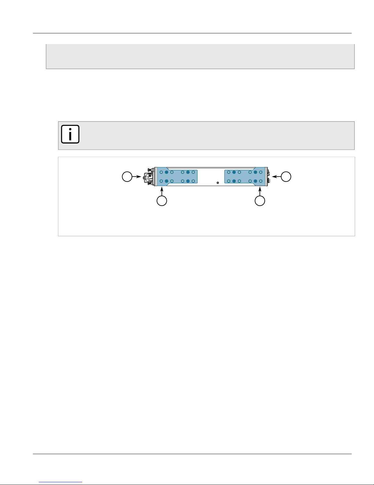
NOTE
Slots 1 and 2 are reserved for 2-port copper, 100Base-FX fiber optic Ethernet and Gigabit Ethernet
(GbE) modules.
Chapter 3
Modules
NOTE
Only one T1/E1 WAN module and up to two DDS modules are supported.
Figure14:Available Chassis Slots
1.Slot 1 2.Slot 2 3.Slot 5 4.Slot 6
CONTENTS
• Section3.1, “Available Modules”
• Section3.2, “Installing/Removing Line Modules”
17
Page 26

Chapter 3
Modules
• Section3.3, “Installing/Removing Power Modules”
Section3.1
Available Modules
The following is a list of all power and line modules available for use in the RUGGEDCOM RX1501. For more
information about individual modules, refer to the RUGGEDCOM RX1500 Series Modules Catalog [https://
support.industry.siemens.com/cs/ca/en/view/109747072].
Power Modules
RUGGEDCOM RX1501
Installation Guide
RUGGEDCOM RX1500PN PS 12 Specifications
Input Range: 9 to 15 VDC
Terminal Type: Screw
RUGGEDCOM RX1500PN PS 12P Specifications
Input Range: 9 to 15 VDC
Terminal Type: Pluggable
RUGGEDCOM RX1500PN PS 24 Specifications
Input Range: 13 to 36 VDC
Terminal Type: Screw
Article Numbers
6GK60150AL170AA0 (Standard)
6GK60150AL170AA1 (Conformal
Coated)
Article Numbers
6GK60150AL180AA0 (Standard)
6GK60150AL180AA1 (Conformal
Coated)
Article Numbers
6GK60150AL110AA0 (Standard)
6GK60150AL110AA1 (Conformal
Coated)
RUGGEDCOM RX1500PN PS 24P Specifications
18 Available Modules
Input Range: 13 to 36 VDC
Terminal Type: Pluggable
Article Numbers
6GK60150AL140AA0 (Standard)
6GK60150AL140AA1 (Conformal
Coated)
Page 27

RUGGEDCOM RX1501
Installation Guide
Chapter 3
Modules
RUGGEDCOM RX1500PN PS 48 Specifications
Input Range: 36 to 72 VDC
Terminal Type: Screw
RUGGEDCOM RX1500PN PS 48P Specifications
Input Range: 36 to 72 VDC
Terminal Type: Pluggable
RUGGEDCOM RX1500PN PS HI Specifications
Input Range: 88 to 300 VDC or
85 to 264 VAC
Terminal Type: Screw
Article Numbers
6GK60150AL120AA0 (Standard)
6GK60150AL120AA1 (Conformal
Coated)
Article Numbers
6GK60150AL150AA0 (Standard)
6GK60150AL150AA1 (Conformal
Coated)
Article Numbers
6GK60150AL130AA0 (Standard)
6GK60150AL130AA1 (Conformal
Coated)
RUGGEDCOM RX1500PN PS HIP Specifications
Input Range: 88 to 300 VDC or
85 to 264 VAC
Terminal Type: Screw
Copper Ethernet Modules
RUGGEDCOM RX1500PN LM CG01 Specifications
Ports: 2
Speed: 10/100/1000Base-TX
Port Type: RJ45
Distance: 100 m (328 ft)
RUGGEDCOM RX1500PN M12 CG03 Specifications
Ports: 2
Speed: 10/100/1000Base-TX
Port Type: M12 (8-Pin, A-Coded)
Distance: 100 m (328 ft)
Article Numbers
6GK60150AL160AA0 (Standard)
6GK60150AL160AA1 (Conformal
Coated)
Article Numbers
6GK60150AL200FC0 (Standard)
6GK60150AL200FC1 (Conformal
Coated)
Article Numbers
6GK60150AL200PB0 (Standard)
6GK60150AL200PB1 (Conformal
Coated)
Available Modules 19
Page 28

Chapter 3
Modules
RUGGEDCOM RX1501
Installation Guide
RUGGEDCOM RX1500PN M12 CG03B Specifications
Ports: 2
Speed: 10/100/1000Base-TX
Port Type: M12 (8-Pin, A-Coded,
Controlled Bypass)
Distance: 100 m (328 ft)
RUGGEDCOM RX1500PN M12 X CG04 Specifications
Ports: 2
Speed: 10/100/1000Base-TX
Port Type: M12 (8-pin, X-Coded)
Distance: 100 m (328 ft)
RUGGEDCOM RX1500PN M12 X CG04B Specifications
Ports: 2
Speed: 10/100/1000Base-TX
Port Type: M12 (8-pin, X-Coded,
Controlled Bypass)
Distance: 100 m (328 ft)
RUGGEDCOM RX1500PN M12 4TX03 Specifications
Ports: 4
Speed: 10/100/1000Base-TX
Port Type: M12 (4-Pin, A-Coded)
Distance: 100 m (328 ft)
Article Numbers
6GK60150AL200PE0 (Standard)
6GK60150AL200PE1 (Conformal
Coated)
Article Numbers
6GK60150AL200PH0 (Standard)
6GK60150AL200PH1 (Conformal
Coated)
Article Numbers
6GK60150AL200PJ0 (Standard)
6GK60150AL200PJ0 (Conformal
Coated)
Article Numbers
6GK60150AL200PC0 (Standard)
6GK60150AL200PC1 (Conformal
Coated)
RUGGEDCOM RX1500PN M12 4TX03B Specifications
Ports: 4
Speed: 10/100/1000Base-TX
Port Type: M12 (8-Pin, A-Coded,
Controlled Bypass)
Distance: 100 m (328 ft)
RUGGEDCOM RX1500PN M12 4TX04 Specifications
Ports: 4
Speed: 10/100/1000Base-TX
Port Type: M12 (4-Pin, D-Coded)
Distance: 100 m (328 ft)
RUGGEDCOM RX1500PN M12 4TX04B Specifications
Ports: 4
Speed: 10/100/1000Base-TX
Port Type: M12 (4-Pin, A-Coded,
Controlled Bypass)
Distance: 100 m (328 ft)
RUGGEDCOM RX1500PN LM 6TX01 Specifications
Ports: 6
Speed: 10/100Base-TX
Port Type: RJ45
Distance: 100 m (328 ft)
Article Numbers
6GK60150AL200PF0 (Standard)
6GK60150AL200PF1 (Conformal
Coated)
Article Numbers
6GK60150AL200PD0 (Standard)
6GK60150AL200PD1 (Conformal
Coated)
Article Numbers
6GK60150AL200PG0 (Standard)
6GK60150AL200PG1 (Conformal
Coated)
Article Numbers
6GK60150AL200NB0 (Standard)
6GK60150AL200NB1 (Conformal
Coated)
20 Available Modules
Page 29

RUGGEDCOM RX1501
Installation Guide
Fiber Optic Ethernet Modules
Chapter 3
Modules
RUGGEDCOM RX1500PN LM 4FX11 Specifications
Mode: MM
Speed: 100Base-FX
Wavelength: 1300 nm
Ports: 4
Port Type: LC
Distance: 2 km (1.2 mi)
RUGGEDCOM RX1500PN LM FL01 Specifications
Mode: MM
Speed: 10Base-FL/100Base-SX
Wavelength: 820 nm
Ports: 3
Port Type: ST
Distance: 2 km (1.2 mi)
RUGGEDCOM RX1500PN LM FG03 Specifications
Mode: SM
Speed: 1000Base-LX
Wavelength: 820 nm
Ports: 4
Port Type: LC
Distance: 10 km (6.2 mi)
Article Numbers
6GK60150AL200BC0 (Standard)
6GK60150AL200BC1 (Conformal
Coated)
Article Numbers
6GK60150AL200BD0 (Standard)
6GK60150AL200BD1 (Conformal
Coated)
Article Numbers
6GK60150AL200EC0 (Standard)
6GK60150AL200EC1 (Conformal
Coated)
SFP Transceiver Modules
RUGGEDCOM RX1500PN LM FG50 Specifications
Sockets: 2
RUGGEDCOM RX1500PN LM FX50 Specifications
Sockets: 4
RUGGEDCOM RX1500PN LM 6FX50 Specifications
Sockets: 6
WAN Modules
NOTE
Only one T1/E1 WAN module and up to two DDS modules are supported.
Article Numbers
6GK60150AL200JB0 (Standard)
6GK60150AL200JB1 (Conformal
Coated)
Article Numbers
6GK60150AL200JC0 (Standard)
6GK60150AL200JC1 (Conformal
Coated)
Article Numbers
6GK60150AL200JD0 (Standard)
6GK60150AL200JD1 (Conformal
Coated)
Available Modules 21
Page 30

Chapter 3
Modules
RUGGEDCOM RX1501
Installation Guide
RUGGEDCOM RX1500PN LM S01 Specifications
Speed: RS232/RS422/RS485
Ports: 6
Port Type: RJ45
RUGGEDCOM RX1500PN LM TC1 Specifications
Interface: T1/E1
Ports: 1
Port Type: RJ48C
RUGGEDCOM RX1500PN LM TC2 Specifications
Interface: T1/E1
Ports: 2
Port Type: RJ48C
RUGGEDCOM RX1500PN LM E02 Specifications
Interface: E1
Ports: 4
Port Type: BNC (75 Ω)
RUGGEDCOM RX1500PN LM D02 Specifications
Speed: 56 kbps (Master/Slave) or
64 kbps (Slave)
Ports: 1
Port Type: RJ48S
Article Numbers
6GK60150AL200KB0 (Standard)
6GK60150AL200KB1 (Conformal
Coated)
Article Numbers
6GK60150AL200MB0 (Standard)
6GK60150AL200MB1
(Conformal Coated)
Article Numbers
6GK60150AL200MC0 (Standard)
6GK60150AL200MC1
(Conformal Coated)
Article Numbers
6GK60150AL200HC0 (Standard)
6GK60150AL200HC1 (Conformal
Coated)
Article Numbers
6GK60150AL200LB0 (Standard)
6GK60150AL200LB1 (Conformal
Coated)
Cellular Modem Modules
RUGGEDCOM RX1500PN LM W11 Specifications
Services: GSM/EDGE/HSPA+
Region: North America (AT&T)
Port Type: 50 Ω SMA
Antennas: 1 x GSM/EDGE/HSPA+,
1 x Receive Diversity (Secondary)
SIM: Dual Mini-SIM (2FF)
RUGGEDCOM RX1500PN LM W12 Specifications
Services: GSM/EDGE/HSPA+
Region: North America (AT&T),
European Union, Australia
Port Type: 50 Ω SMA
Antennas: 2 x GSM/EDGE/HSPA+,
2 x Receive Diversity (Secondary)
SIM: Dual Mini-SIM (2FF)
RUGGEDCOM RX1500PN LM W21 Specifications
Services: EVDO Rev A
Region: North America (Verizon)
Port Type: 50 Ω SMA
Article Numbers
6GK60150AL200WB0 (Standard)
6GK60150AL200WB1
(Conformal Coated)
Article Numbers
6GK60150AL200WC0 (Standard)
6GK60150AL200WC1
(Conformal Coated)
Article Numbers
6GK60150AL200WD0 (Standard)
6GK60150AL200WD1
(Conformal Coated)
22 Available Modules
Page 31

RUGGEDCOM RX1501
Installation Guide
Chapter 3
Modules
Antennas: 1 x EVDO Rev A, 1 x
Receive Diversity (Secondary)
SIM: Dual Mini-SIM (2FF)
RUGGEDCOM RX1500PN LM W22 Specifications
Services: EVDO Rev A
Region: North America (Verizon)
Port Type: 50 Ω SMA
Antennas: 2 x EVDO Rev A, 2 x
Receive Diversity (Secondary)
SIM: Dual Mini-SIM (2FF)
RUGGEDCOM RX1500PN LM W32 Specifications
Services: EVDO Rev A
Region: North America (Verizon)
Port Type: 50 Ω SMA
Antennas: 1 x GSM/EDGE/HSPA
+, 1 x EVDO Rev A, 2 x Receive
Diversity (Secondary)
SIM: Dual Mini-SIM (2FF)
RUGGEDCOM RX1500PN LM W41 Specifications
Services: EDGE/GPRS/GSM/UMTS/
HSPA+/LTE/GNSS
Region: European Union
Port Type: 50 Ω SMA
Antennas: 1 x LTE Main, 1 x LTE
MIMO, 1 x GPS
SIM: Dual Mini-SIM (2FF)
Article Numbers
6GK60150AL200WE0 (Standard)
6GK60150AL200WE0
(Conformal Coated)
Article Numbers
6GK60150AL200WF0 (Standard)
6GK60150AL200WF0
(Conformal Coated)
Article Numbers
6GK60150AL200WG0 (Standard)
6GK60150AL200WG1
(Conformal Coated)
RUGGEDCOM RX1500PN LM W51 Specifications
Services: EDGE/GPRS/GSM/UMTS/
HSPA+/LTE/GNSS
Region: North America (AT&T,
Rogers, Bell, Telus)
Port Type: 50 Ω SMA
Antennas: 1 x LTE Main, 1 x LTE
MIMO, 1 x GPS
SIM: Dual Mini-SIM (2FF)
RUGGEDCOM RX1500PN LM W61 Specifications
Services: EDGE/GPRS/GSM/UMTS/
HSPA+/LTE/GNSS
Region: North America (Verizon,
Sprint)
Port Type: 50 Ω SMA
Antennas: 1 x LTE Main, 1 x LTE
MIMO, 1 x GPS
SIM: Dual Mini-SIM (2FF)
RUGGEDCOM RX1500PN LM W81 Specifications
Services: EDGE/GPRS/GSM/UMTS/
HSPA+/LTE/GNSS
Region: Asia-Pacific
Port Type: 50 Ω SMA
Article Numbers
6GK60150AL200WH0 (Standard)
6GK60150AL200WH1
(Conformal Coated)
Article Numbers
6GK60150AL200WJ0 (Standard)
6GK60150AL200WJ1 (Conformal
Coated)
Article Numbers
6GK60150AL200WK0 (Standard)
6GK60150AL200WK1
(Conformal Coated)
Available Modules 23
Page 32

Chapter 3
Modules
RUGGEDCOM APE Modules
CAUTION!
Electrical hazard – risk of power failure. Do not install more than two RUGGEDCOM APE modules.
Installing more than two of this type of module can lead to power fluctuations and irregular shut
downs.
RUGGEDCOM RX1501
Installation Guide
Antennas: 1 x LTE Main, 1 x LTE
MIMO, 1 x GPS
SIM: Dual Mini-SIM (2FF)
RUGGEDCOM RX1500PN LM APE1402 Specifications
Operating System: Debian Linux®
Processor: Intel Atom E660 1.3
GHz, 512 KB L2 Cache
RAM: 2 GB DDR2, 800 MHz, 32-
bit
Disk: 8 GB SATA, Solid State
Networking: Realtek RTL8111,
RJ45 Gigabit Ethernet Interface
USB: 2 x USB 2.0
Video: Intel 4108 Graphics
Processor, DVI-D
RUGGEDCOM RX1500PN LM APE1402W7 Specifications
Operating System: Windows®
Embedded Standard 7
Processor: Intel Atom E660 1.3
GHz, 512 KB L2 Cache
RAM: 2 GB DDR2, 800 MHz, 32bit
Disk: 8 GB SATA, Solid State
Networking: Realtek RTL8111,
RJ45 Gigabit Ethernet Interface
USB: 2 x USB 2.0
Video: Intel 4108 Graphics
Processor, DVI-D
Article Numbers
6GK60150AL200GB0 (Standard)
6GK60150AL200GB1 (Conformal
Coated)
a
Article Numbers
6GK60150AL200GC0 (Standard)
6GK60150AL200GC1 (Conformal
Coated)
a
RUGGEDCOM RX1500PN LM APE1404 Specifications
24 Available Modules
Operating System: Debian Linux®
Processor: Intel Atom E660T 1.3
GHz, 512 KB L2 Cache
RAM: 2 GB DDR2, 800 MHz, 32-
bit
Disk: 16 GB SATA, Solid State
Networking: Realtek RTL8111,
RJ45 Gigabit Ethernet Interface
USB: 2 x USB 2.0
Video: Intel 4108 Graphics
Processor, DVI-D
a
Article Numbers
6GK60150AL200GD0 (Standard)
6GK60150AL200GD1 (Conformal
Coated)
Page 33

RUGGEDCOM RX1501
Installation Guide
Chapter 3
Modules
RUGGEDCOM RX1500PN LM APE1404W7 Specifications
Operating System: Windows®
Embedded Standard 7
Processor: Intel Atom E660T 1.3
GHz, 512 KB L2 Cache
RAM: 2 GB DDR2, 800 MHz, 32bit
Disk: 16 GB SATA, Solid State
Networking: Realtek RTL8111,
RJ45 Gigabit Ethernet Interface
USB: 2 x USB 2.0
Video: Intel 4108 Graphics
Processor, DVI-D
RUGGEDCOM RX1500PN LM APE1404CKP Specifications
Operating System: Check Point
GAiA™ OS
Processor: Intel Atom E660T 1.3
GHz, 512 KB L2 Cache
RAM: 2 GB DDR2, 800 MHz, 32bit
Disk: 16 GB SATA, Solid State
Networking: Realtek RTL8111,
RJ45 Gigabit Ethernet Interface
USB: 2 x USB 2.0
Video: Intel 4108 Graphics
Processor, DVI-D
a
Maximum combined USB device power consumption is 500 mA at 5 V.
Article Numbers
6GK60150AL200GE0 (Standard)
6GK60150AL200GE1 (Conformal
Coated)
a
Article Numbers
6GK60150AL200GF0 (Standard)
6GK60150AL200GF1 (Conformal
Coated)
a
Section3.2
Installing/Removing Line Modules
Upon installing a new line module in the device, all features associated with the module are available in
RUGGEDCOM ROX II. For more information, refer to the RUGGEDCOM ROX II User Guide for the RUGGEDCOM
RX1501.
Once a line module is removed, all the features associated with the module are hidden or disabled in RUGGEDCOM
ROX II.
CAUTION!
Electrical hazard – risk of power failure. Do not install more than two RUGGEDCOM APE modules.
Installing more than two of this type of module can lead to power fluctuations and irregular shut
downs.
IMPORTANT!
Only one WAN line module is supported per chassis.
Installing/Removing Line Modules 25
Page 34

Chapter 3
1
2
3
Modules
RUGGEDCOM RX1501
Installation Guide
CAUTION!
Contamination hazard – risk of equipment damage. Prevent the ingress of water, dirts and other debris
that may lead to premature equipment failure. Always make sure slots are not left empty and open
ports are protected with plugs or covers.
Removing a Module
To remove a line module, do the following:
1. Make sure power to the device has been disconnected and wait approximately two minutes for any remaining
energy to dissipate.
2. [Optional] If the device is installed in a rack, remove it from the rack.
3. Loosen the screws that secure the module.
4. Pull the module from the chassis to disconnect it.
Figure15:Removing a Module
1.Module 2.Chassis 3.Screw
5. Install a new module or a blank module (to prevent the ingress of dust and dirt).
6. [Optional] If necessary, install the device in the rack.
7. Connect power to the device.
Installing a Module
To install a line module, do the following:
1. Make sure power to the device has been disconnected and wait approximately two minutes for any remaining
energy to dissipate.
2. [Optional] If the device is installed in a rack, remove it from the rack.
3. Remove the current module from the slot.
4. Insert the new module into the slot.
26 Installing/Removing Line Modules
Page 35

RUGGEDCOM RX1501
1
2
3
1
Installation Guide
Figure16:Installing a Module
1.Module 2.Chassis 3.Screw
5. Tighten the screws to secure the module.
6. [Optional] If necessary, install the device in the rack.
7. Connect power to the device.
Chapter 3
Modules
Section3.3
Installing/Removing Power Modules
The RUGGEDCOM RX1501 supports a single power module.
Figure17: Power Module
1.Power Module
CAUTION!
Contamination hazard – risk of equipment damage. Prevent the ingress of water, dirts and other debris
that may lead to premature equipment failure. Always make sure slots are not left empty.
Removing a Power Module
To remove a power module, do the following:
1. Loosen the screws that secure the module to the chassis until the module can be removed.
2. Slide the module out of the chassis.
Installing/Removing Power Modules 27
Page 36

Chapter 3
3
2
1
Modules
RUGGEDCOM RX1501
Installation Guide
Figure18:Removing a Power Supply
1.Chassis 2.Power Supply 3.Screws
DANGER!
Electrocution hazard – risk of serious personal injury or death. Make sure power to the module is
turned off before servicing the power supply terminal.
3. Turn off power to the module.
4. Disconnect the power supply wiring from the terminal block. Alternatively, for convenience, remove the
terminal block with the wiring still connected and set it aside to be connected later to the new module.
5. Install a new or blank module to prevent the ingress of dust and dirt.
Installing a Power Module
To install a power module, do the following:
1. If equipped, remove the existing module.
2. If applicable, connect the supplied terminal block to the module or connect the terminal block from the
previous module.
3. Confirm or connect the wiring from the power supply to the module. For more information, refer to
Section2.6, “Connecting Power” .
4. Insert the module into the empty slot.
28 Installing/Removing Power Modules
Page 37

RUGGEDCOM RX1501
3
2
1
Installation Guide
Figure19:Installing a Power Module
1.Chassis 2.Power Module 3.Screws
5. Hand-tighten the screws to secure the power module to the chassis.
6. Turn on power to the module and confirm the module is receiving and supplying power. This is indicated by
the LEDs on the module.
Chapter 3
Modules
LED State Description
O Green The module is supplying power
I Green The module is receiving power
Installing/Removing Power Modules 29
Page 38

Chapter 3
Modules
RUGGEDCOM RX1501
Installation Guide
30 Installing/Removing Power Modules
Page 39

RUGGEDCOM RX1501
Installation Guide
Technical Specifications
This section provides important technical specifications related to the device.
CONTENTS
• Section4.1, “Power Supply Specifications”
• Section4.2, “Failsafe Relay Specifications”
• Section4.3, “Operating Environment”
• Section4.4, “Mechanical Specifications”
Section4.1
Technical Specifications
Chapter 4
Power Supply Specifications
Power
Supply Type
HI
HIP
24
24P
48
48P
12
12P
a
Power consumption varies based on the device configuration.
b
Based on #16 AWG wiring.
c
(T) denotes time-delay fuse.
Input Range
Min Max
88 VDC 300 VDC
85 VAC 264 VAC
88 VDC 300 VDC
85 VAC 264 VAC
13 VDC 36 VDC 10 A(T)
36 VDC 72 VDC 3.15 A(T)
9 VDC 15 VDC 12 A 67 W 5.5 m (18 ft)
Internal
Fuse Rating
3.15 A(T)
3.15 A(T)
c
c
c
c
Maximum Power
Consumption
65 W —
65 W —
63.5 W 9.4 m (30.8 ft)
60 W 45.5 m (149 ft)
a
Cable Length
Maximum
b
Insulation
2800 VDC
for 1 minute
1500 VDC
for 1 minute
1500 VAC or
2121 VDC
for 1 minute
Power Supply Specifications 31
Page 40

Chapter 4
Technical Specifications
Section4.2
Failsafe Relay Specifications
Maximum Switching Voltage Rated Switching Current Isolation
RUGGEDCOM RX1501
Installation Guide
30 VDC 5 A
250 VAC 6.25 A
Section4.3
2800 VDC for 1 minute
Operating Environment
The RUGGEDCOM RX1501 is rated to operate under the following environmental conditions.
IMPORTANT!
Temperature limits for select line modules may differ from that which can be withstood by the
RUGGEDCOM RX1501. Make sure the selected modules are rated for the expected environmental
conditions before deployment. For more information, refer to the RUGGEDCOM RX1501 Series
Modules Catalog.
Parameter Range Comments
Ambient Operating Temperature -40 to 85 °C
Ambient Relative Humidity 5% to 95% Non-condensing
Ambient Storage Temperature -40 to 85 °C
d
Maximum ambient operating temperature is 70 °C (158 °F) when the device is installed along with Underwriter Laboratories (UL) listed devices.
(-40 to 185 °F)
(-40 to 185 °F)
Measured from a 30 cm (12 in) radius surrounding the center of the
d
enclosure.
Section4.4
Mechanical Specifications
Dimensions Refer to Chapter5, Dimension Drawings
Weight Approximately 4.7 kg (10.3 lb)
Ingress Protection IP40
Enclosure Aluminum
32 Failsafe Relay Specifications
Page 41

RUGGEDCOM RX1501
440.9
296.7
44.2
Installation Guide
Dimension Drawings
Dimension Drawings
Chapter 5
NOTE
All dimensions are in millimeters, unless otherwise stated.
Figure20:Overall Dimensions
33
Page 42

Chapter 5
11.7
21.1
28.7
51.1
161.0
212.1
4.7
6.35
463.8
31.8
160.0
489.2
51.6
479.0
134.6
68.8
21.1
11.7
29.0
51.1
161.0
212.1
Dimension Drawings
RUGGEDCOM RX1501
Installation Guide
Figure21:Rack Mount Dimensions
Figure22:Panel and Din Rail Mount Dimensions
34
Page 43

RUGGEDCOM RX1501
19.7
151.4
102.9
113.3
162.5
162.5
40.6
151.8
102.9
113.4
Installation Guide
Figure23:Line Module Dimensions
Dimension Drawings
Chapter 5
Figure24:Power Module Dimensions
35
Page 44

Chapter 5
Dimension Drawings
RUGGEDCOM RX1501
Installation Guide
36
Page 45

RUGGEDCOM RX1501
Installation Guide
Certification
The RUGGEDCOM RX1501 device has been thoroughly tested to guarantee its conformance with recognized
standards and has received approval from recognized regulatory agencies.
NOTE
Certifications related to individual modules are detailed in the RUGGEDCOM Modules Catalog for the
device available online.
CONTENTS
• Section6.1, “Approvals”
• Section6.2, “EMC and Environmental Type Tests”
Chapter 6
Certification
Section6.1
Approvals
This section details the standards to which the RUGGEDCOM RX1501 complies.
CONTENTS
• Section6.1.1, “UL”
• Section6.1.2, “TÜV SÜD”
• Section6.1.3, “European Union (EU)”
• Section6.1.4, “FCC”
• Section6.1.5, “FDA/CDRH”
• Section6.1.6, “ISED”
• Section6.1.7, “RoHS”
• Section6.1.8, “Other Approvals”
Section6.1.1
UL
This device is certified by the Underwriters Laboratory (UL) to meet the requirements of the following standards:
• CAN/CSA-C22.2 NO. 60950-1-07 (R2012)
Information Technology Equipment – Safety – Part 1: General Requirements (Bi-National standard, with UL
60950-1)
Approvals 37
Page 46

Chapter 6
Certification
• UL 60950-1
Information Technology Equipment – Safety – Part 1: General Requirements)
Certification is filed under E361664.
Section6.1.2
TÜV SÜD
This device is certified by TÜV SÜD to meet the requirements of the following standards:
• CAN/CSA-C22.2 NO. 60950-1-07 (R2012)
Information Technology Equipment – Safety – Part 1: General Requirements (Bi-National standard, with UL
60950-1)
• UL 60950-1
Information Technology Equipment – Safety – Part 1: General Requirements)
Section6.1.3
European Union (EU)
RUGGEDCOM RX1501
Installation Guide
This device is declared by Siemens Canada Ltd to comply with essential requirements and other relevant provisions
of the following EU directives:
• Directive 2014/30/EU
Directive 2014/30/EU of the European Parliament and of the Council of 26 February 2014 on the harmonisation
of the laws of the Member States relating to electromagnetic compatibility (recast) Text with EEA relevance
• Directive 2014/35/EU
Directive 2014/35/EU of the European Parliament and of the Council of 26 February 2014 on the harmonisation
of the laws of the Member States relating to the making available on the market of electrical equipment
designed for use within certain voltage limits Text with EEA relevance
• Directive 2011/65/EU
Directive 2011/65/EU of the European Parliament and of the Council of 8 June 2011 on the restriction of the use
of certain hazardous substances in electrical and electronic equipment Text with EEA relevance
• Directive 1999/5/EC
Directive 1999/5/EC of the European Parliament and of the Council of 9 March 1999 on radio equipment and
telecommunications terminal equipment and the mutual recognition of their conformity
• EN 60950-1
Information Technology Equipment – Safety – Part 1: General Requirements
• EN 61000-3-2
Electromagnetic compatibility (EMC) – Part 3-2: Limits – Limits for harmonic current emissions (equipment
input current ≤ 16 A per phase)
• EN 61000-3-3
Electromagnetic compatibility (EMC) – Part 3-3: Limits – Limitation of voltage changes, voltage fluctuations and
flicker in public low-voltage supply systems, for equipment with rated current ≤16 A per phase and not subject
to conditional connection
• EN 61000-6-2
Electromagnetic Compatibility (EMC) – Part 6-2: Generic Standards – Immunity for Industrial Environments
38 TÜV SÜD
Page 47

RUGGEDCOM RX1501
0680
Installation Guide
• EN 60825-1
Safety of Laser Products – Equipment Classification and Requirements
• EN 50581
Technical Documentation for the Assessment of Electrical and Electronic Products with Respect to the Restriction
of Hazardous Substances
• EN 55022
Information Technology Equipment – Radio Disturbance Characteristics – Limits and Methods of Measurement
The device is marked with a CE marking and notified body number, and can be used throughout the European
community.
A copy of the CE Declaration of Conformity is available from Siemens Canada Ltd. For contact information, refer to
“Contacting Siemens ” .
Section6.1.4
FCC
Chapter 6
Certification
This device has been tested and found to comply with the limits for a Class A digital device, pursuant to Part 15 of
the FCC Rules. These limits are designed to provide reasonable protection against harmful interference when the
equipment is operated in a commercial environment.
This device generates, uses and can radiate radio frequency energy and, if not installed and used in accordance
with the instruction manual, may cause harmful interference to radio communications. Operation of this
equipment in a residential area is likely to cause harmful interference in which case users will be required to
correct the interference at their own expense.
IMPORTANT!
Changes or modifications not expressly approved by the party responsible for compliance could void
the user's authority to operate this device.
Section6.1.5
FDA/CDRH
This device meets the requirements of the following U.S. Food and Drug Administration (FDA) standard:
• Title 21 Code of Federal Regulations (CFR) – Chapter I – Sub-chapter J – Radiological Health
Section6.1.6
ISED
This device is declared by Siemens Canada Ltd to meet the requirements of the following ISED (Innovation Science
and Economic Development Standard Canada) standard:
• CAN ICES-3 (A)/NMB-3 (A)
FCC 39
Page 48

Chapter 6
Certification
Section6.1.7
RUGGEDCOM RX1501
Installation Guide
RoHS
This device is declared by Siemens Canada Ltd to meet the requirements of the following RoHS (Restriction of
Hazardous Substances) directives for the restricted use of certain hazardous substances in electrical and electronic
equipment:
• China RoHS 2
Administrative Measure on the Control of Pollution Caused by Electronic Information Products
A copy of the Material Declaration is available online at https://support.industry.siemens.com/cs/us/en/
view/109738831 .
Section6.1.8
Other Approvals
This device meets the requirements of the following additional standards:
• IEEE 1613
IEEE Standard Environmental and Testing Requirements for Communications Networking Devices in Electric
Power Substations
• IEC 61000-6-2
Electromagnetic Compatibility (EMC) – Part 6-2: Generic Standards – Immunity for Industrial Environments
• IEC 61850-3
Communication Networks and Systems in Substations – Part 3: General Requirements
Section6.2
EMC and Environmental Type Tests
The RUGGEDCOM RX1501 has passed the following Electromagnetic Compatibility (EMC) and environmental tests.
EMC Type Test for IEC 61850-3
Test Description Test Levels
Enclosure Contact ± 8 kVIEC 61000-4-2 ESD
Enclosure Air ± 15 kV
IEC 61000-4-3 Radiated RFI Enclosure Ports 20 V/m
IEC 61000-4-4 Burst (Fast Transient)
IEC 61000-4-5 Surge Signal ports ± 4 kV Line-to-Ground
Signal ports ± 4 kV @ 2.5 kHz
DC Power Ports
AC Power Ports
Earth ground ports
± 4 kV 4
± 2 kV Line-to-Line
Severity
Levels
4
a
Note
4
40 RoHS
Page 49

RUGGEDCOM RX1501
Installation Guide
Chapter 6
Certification
Test Description Test Levels
DC Power Ports ± 2 kV Line-to-Ground
± 1 kV Line-to-Line
AC Power Ports ± 4 kV Line-to-Ground
± 2 kV Line-to-Line
IEC 61000-4-6 Induced (Conducted) RFI
IEC 61000-4-8 Magnetic Field Enclosure Ports
IEC 61000-4-11 Voltage Dips and Interrupts AC Power Ports 30% for 1 period
IEC 61000-4-12 Damped Oscillatory
Signal ports
DC Power Ports
AC Power Ports
Earth ground ports
Signal ports
DC Power Ports
AC Power Ports
10 V 3
100 A/m, continuous
1000 A/m for 1 s
1000 A/m for 1 s 5
60% for 50 periods
2.5 kV common, 1 kV
differential mode @1 MHz
Severity
Levels
3
4
a
Note
3
Signal portsIEC 61000-4-16 Mains Frequency Voltage
DC Power Ports
IEC 61000-4-17 Ripple on DC Power Supply DC Power Ports 10% 3
IEC 61000-4-29 Voltage Dips and Interrupts DC Power Ports 30% for 0.1 s
IEC 60255-5
a
Siemens-specified severity levels
Dielectric Strength
HV Impulse
Signal ports 2 kV (Failsafe Relay output)
DC Power Ports 1.5 kV
AC Power Ports 2 kV
Signal ports 5 kV (Failsafe Relay output)
DC Power Ports
AC Power Ports
30 V Continuous
300 V for 1 s
60% for 0.1 s
100% for 0.05 s
5 kV
EMC Immunity Type Tests for IEEE 1613
NOTE
The RUGGEDCOM RX1501 meets Class 2 requirements for an all-fiber configuration and Class 1
requirements for copper ports. Class 1 allows for temporary communication loss, while Class 2 requires
error-free and interrupted communications.
4
EMC and Environmental Type Tests 41
Page 50

Chapter 6
Certification
RUGGEDCOM RX1501
Installation Guide
Description Test Levels
HV Impulse
Dielectric Strength
Fast Transient
Oscillatory
Radiated RFI Enclosure ports 35 V/m
Signal ports 5 kV (Failsafe Relay Output)
DC Power Ports
AC Power Ports
Signal ports 2 kV
DC Power Ports 1.5 kV
AC Power Ports 2 kV
Signal ports ± 4 kV @ 2.5 kHz
DC Power Ports
AC Power Ports
Earth ground ports
Signal ports 2.5 kV common mode @1MHz
DC Power Ports
AC Power Ports
Enclosure Contact ± 8 kVESD
Enclosure Air ± 15 kV
2.5 kV common
1 kV differential mode @ 1 MHz
5 kV
± 4 kV
Environmental Type Tests
Test Description Test Levels
IEC 60068-2-1 Cold Temperature Test Ad -40 °C (-40 °F), 16 Hours
IEC 60068-2-2 Dry Heat Test Bd 85 °C (185 °F), 16 Hours
IEC 60068-2-30 Humidity (Damp Heat, Cyclic) Test Db 95% (non-condensing),
IEC 60255-21-1 Vibration 2 g @ 10-150 Hz Class 2
IEC 60255-21-3 Seismic Method A Level 2
MIL-STD-810G Altitude 12192 m (40000 ft)
Severity
Levels
55 °C (131 °F), 6 cycles
Shock 30 g @ 11 ms Class 2IEC 60255-21-2
Bump 10 g @ 16 ms Class 1
Long Life (Random Vibration)IEC 61373
Shock
Category 1 Class B
@ 40 °C, 90 minutes
42 EMC and Environmental Type Tests
 Loading...