

Page 1
Preface
RUGGEDCOM RX1400
Installation Guide
Introduction
Installing the Device
Communication Ports
Technical Specifications
Dimension Drawings
Certification
1
2
3
4
5
6
08/2017
RC1103-EN-08
Page 2

RUGGEDCOM RX1400
Installation Guide
Copyright © 2017 Siemens Canada Ltd
All rights reserved. Dissemination or reproduction of this document, or evaluation and communication of its contents, is not authorized
except where expressly permitted. Violations are liable for damages. All rights reserved, particularly for the purposes of patent application or
trademark registration.
This document contains proprietary information, which is protected by copyright. All rights are reserved. No part of this document may be
photocopied, reproduced or translated to another language without the prior written consent of Siemens Canada Ltd.
Disclaimer Of Liability
Siemens has verified the contents of this document against the hardware and/or software described. However, deviations between the product
and the documentation may exist.
Siemens shall not be liable for any errors or omissions contained herein or for consequential damages in connection with the furnishing,
performance, or use of this material.
The information given in this document is reviewed regularly and any necessary corrections will be included in subsequent editions. We
appreciate any suggested improvements. We reserve the right to make technical improvements without notice.
Registered Trademarks
RUGGEDCOM™ and ROS™ are trademarks of Siemens Canada Ltd.
Linux® is the registered trademark of Linus Torvalds in the United States and other countries.
The registered trademark Linux® is used pursuant to a sublicense from LMI, the exclusive licensee of Linus Torvalds, owner of the mark on a
world-wide basis.
Other designations in this manual might be trademarks whose use by third parties for their own purposes would infringe the rights of the
owner.
Security Information
Siemens provides products and solutions with industrial security functions that support the secure operation of plants, machines, equipment
and/or networks. They are important components in a holistic industrial security concept. With this in mind, Siemens' products and solutions
undergo continuous development. Siemens recommends strongly that you regularly check for product updates.
For the secure operation of Siemens products and solutions, it is necessary to take suitable preventive action (e.g. cell protection concept) and
integrate each component into a holistic, state-of-the-art industrial security concept. Third-party products that may be in use should also be
considered. For more information about industrial security, visit http://www.siemens.com/industrialsecurity.
To stay informed about product updates as they occur, sign up for a product-specific newsletter. For more information, visit http://
support.automation.siemens.com.
Warranty
Siemens warrants this product for a period of five (5) years from the date of purchase, conditional upon the return to factory for maintenance
during the warranty term. This product contains no user-serviceable parts. Attempted service by unauthorized personnel shall render all
warranties null and void. The warranties set forth in this article are exclusive and are in lieu of all other warranties, performance guarantees
and conditions whether written or oral, statutory, express or implied (including all warranties and conditions of merchantability and fitness for
a particular purpose, and all warranties and conditions arising from course of dealing or usage or trade). Correction of nonconformities in the
manner and for the period of time provided above shall constitute the Seller’s sole liability and the Customer’s exclusive remedy for defective
or nonconforming goods or services whether claims of the Customer are based in contract (including fundamental breach), in tort (including
negligence and strict liability) or otherwise.
For warranty details, visit www.siemens.com/ruggedcom or contact a Siemens customer service representative.
Contacting Siemens
Address
Siemens Canada Ltd
Telephone
Toll-free: 1 888 264 0006
E-mail
ruggedcom.info.i-ia@siemens.com
ii
Page 3

RUGGEDCOM RX1400
Installation Guide
Industry Sector
300 Applewood Crescent
Concord, Ontario
Canada, L4K 5C7
Tel: +1 905 856 5288
Fax: +1 905 856 1995
Web
www.siemens.com/ruggedcom
iii
Page 4

RUGGEDCOM RX1400
Installation Guide
iv
Page 5

RUGGEDCOM RX1400
Installation Guide
Table of Contents
Table of Contents
Preface ............................................................................................................ ix
Alerts .................................................................................................................................................. ix
Related Documents .............................................................................................................................. x
Accessing Documentation ..................................................................................................................... x
Training ............................................................................................................................................... x
Customer Support ................................................................................................................................ x
Chapter 1
Introduction ..................................................................................................... 1
1.1Feature Highlights ........................................................................................................................ 1
1.2Description ................................................................................................................................... 2
Chapter 2
Installing the Device ......................................................................................... 5
2.1General Procedure ........................................................................................................................ 6
2.2Required Tools and Materials ......................................................................................................... 6
2.3Cabling Recommendations ............................................................................................................ 7
2.3.1Protection On Twisted-Pair Data Ports .................................................................................. 7
2.3.2Gigabit Ethernet 1000Base-TX Cabling Recommendations ..................................................... 7
2.4Installing the Device in Hazardous Locations ................................................................................... 8
2.5Mounting the Device .................................................................................................................... 9
2.5.1Mounting the Device to a Rack ........................................................................................... 9
2.5.2Mounting the Device on a DIN Rail .................................................................................... 10
2.5.3Mounting the Device to a Panel ........................................................................................ 11
2.6Connecting the Antennas ............................................................................................................ 12
2.6.1Available Antennas ........................................................................................................... 13
2.6.2Connecting LTE Antennas ................................................................................................. 15
2.6.3Connecting a GPS Antenna ............................................................................................... 16
2.6.4Connecting WLAN Antennas ............................................................................................. 18
2.7Installing the SIM Cards ............................................................................................................... 19
2.8Inserting/Removing the MicroSD Card ........................................................................................... 20
2.9Connecting the Failsafe Alarm Relay ............................................................................................. 21
2.10Connecting Power ..................................................................................................................... 21
2.10.1Connecting High AC/DC Power ........................................................................................ 22
2.10.2Connecting Low DC Power .............................................................................................. 22
v
Page 6

Table of Contents
2.11Connecting to the Device .......................................................................................................... 23
2.12Configuring the Device .............................................................................................................. 24
Chapter 3
RUGGEDCOM RX1400
Installation Guide
Communication Ports ...................................................................................... 25
3.1Fast Ethernet Ports ...................................................................................................................... 25
3.2SFP Transceivers ......................................................................................................................... 26
3.3Serial Ports ................................................................................................................................. 27
Chapter 4
Technical Specifications .................................................................................. 29
4.1Power Supply Specifications ........................................................................................................ 29
4.2Failsafe Alarm Relay Specifications ............................................................................................... 29
4.3Fast Ethernet Port Specifications .................................................................................................. 30
4.4Serial Port Specifications ............................................................................................................. 30
4.5Cellular Modem Specifications ..................................................................................................... 31
4.5.1LTE Specifications ............................................................................................................ 31
4.5.2GNSS Specifications .......................................................................................................... 32
4.6WLAN Specifications .................................................................................................................... 33
4.7Operating Environment ............................................................................................................... 34
4.8Mechanical Specifications ............................................................................................................ 34
Chapter 5
Dimension Drawings ....................................................................................... 35
Chapter 6
Certification .................................................................................................... 39
6.1Approvals ................................................................................................................................... 39
6.1.1 CSA ................................................................................................................................. 40
6.1.2CSA/Sira ........................................................................................................................... 40
6.1.3TÜV SÜD ......................................................................................................................... 41
6.1.4European Union (EU) ....................................................................................................... 41
6.1.5 FCC ................................................................................................................................. 43
6.1.6FDA/CDRH ........................................................................................................................ 43
6.1.7 ISO .................................................................................................................................. 43
6.1.8 ISED ................................................................................................................................ 44
6.1.9 IFT .................................................................................................................................. 47
6.1.10 RRA ............................................................................................................................... 47
6.1.11ANATEL ......................................................................................................................... 47
6.1.12ICASA ............................................................................................................................ 48
6.1.13ACMA ............................................................................................................................ 48
6.1.14RoHS ............................................................................................................................. 49
vi
Page 7

RUGGEDCOM RX1400
Installation Guide
6.2EMC and Environmental Type Tests .............................................................................................. 49
Table of Contents
6.1.15Other Approvals ............................................................................................................. 49
vii
Page 8

Table of Contents
RUGGEDCOM RX1400
Installation Guide
viii
Page 9
RUGGEDCOM RX1400
Installation Guide
Preface
This guide describes the RUGGEDCOM RX1400. It describes the major features of the device, installation,
commissioning and important technical specifications.
It is intended for use by network technical support personnel who are responsible for the installation,
commissioning and maintenance of the device. It is also recommended for use by network and system planners,
system programmers, and line technicians.
CONTENTS
• “Alerts”
• “Related Documents”
• “Accessing Documentation”
• “Training”
• “Customer Support”
Preface
Alerts
The following types of alerts are used when necessary to highlight important information.
DANGER!
DANGER alerts describe imminently hazardous situations that, if not avoided, will result in death or
serious injury.
WARNING!
WARNING alerts describe hazardous situations that, if not avoided, may result in serious injury and/or
equipment damage.
CAUTION!
CAUTION alerts describe hazardous situations that, if not avoided, may result in equipment damage.
IMPORTANT!
IMPORTANT alerts provide important information that should be known before performing a procedure
or step, or using a feature.
NOTE
NOTE alerts provide additional information, such as facts, tips and details.
Alerts ix
Page 10
Preface
RUGGEDCOM RX1400
Installation Guide
Related Documents
Other documents that may be of interest include:
• RUGGEDCOM ROX II User Guide for the RUGGEDCOM RX1400
Accessing Documentation
The latest user documentation for RUGGEDCOM RX1400 is available online at www.siemens.com/ruggedcom. To
request or inquire about a user document, contact Siemens Customer Support.
Training
Siemens offers a wide range of educational services ranging from in-house training of standard courses on
networking, Ethernet switches and routers, to on-site customized courses tailored to the customer's needs,
experience and application.
Siemens' Educational Services team thrives on providing our customers with the essential practical skills to make
sure users have the right knowledge and expertise to understand the various technologies associated with critical
communications network infrastructure technologies.
Siemens' unique mix of IT/Telecommunications expertise combined with domain knowledge in the utility,
transportation and industrial markets, allows Siemens to provide training specific to the customer's application.
For more information about training services and course availability, visit www.siemens.com/ruggedcom or
contact a Siemens Sales representative.
Customer Support
Customer support is available 24 hours, 7 days a week for all Siemens customers. For technical support or general
information, contact Siemens Customer Support through any of the following methods:
Online
Visit http://www.siemens.com/automation/support-request to submit a Support Request (SR) or check on the status of an
existing SR.
Telephone
Call a local hotline center to submit a Support Request (SR). To locate a local hotline center, visit http://
www.automation.siemens.com/mcms/aspa-db/en/automation-technology/Pages/default.aspx.
Mobile App
Install the Industry Online Support app by Siemens AG on any Android, Apple iOS or Windows mobile device and be able to:
• Access Siemens' extensive library of support documentation, including FAQs and manuals
• Submit SRs or check on the status of an existing SR
• Contact a local Siemens representative from Sales, Technical Support, Training, etc.
• Ask questions or share knowledge with fellow Siemens customers and the support community
x Related Documents
Page 11
RUGGEDCOM RX1400
Installation Guide
Introduction
The RUGGEDCOM RX1400 is a multi-protocol intelligent node that combines Ethernet switch, routing and firewall
functionality with various wide area connectivity options.
The RUGGEDCOM RX1400 switch, with its rugged metal housing, is designed for DIN rail, panel or rack mounting.
The RUGGEDCOM RX1400 provides a high level of immunity to electromagnetic interference, heavy electrical
surges, extreme temperature and humidity for reliable operation in harsh environments.
The device has IP40 degree protection, does not use internal fans for cooling and supports a -40 to 85 °C (-40 to
185 °F) extended temperature range. It is also certified for use in Class I, Division 2, Zone 2 hazardous locations.
Primary benefits include:
• Cost effective solution for large scale deployments
• Space-saving installation
• Reduced maintenance costs
• Customer data protection
Chapter 1
Introduction
• Support for additional applications
The RUGGEDCOM RX1400 is designed to support primary communications over public mobile networks and
leverage enhanced capabilities of mobile networks, while making reliable and secure connections for mission
critical applications in electric utility substations, traffic control cabinets, railway applications, oil and gas and
other harsh environment applications.
IMPORTANT!
To comply with FCC regulations, this device must only be used for mobile and fixed applications.
CONTENTS
• Section1.1, “Feature Highlights”
• Section1.2, “Description”
Section1.1
Feature Highlights
Cellular Interface
• LTE: 700- B13, B17, 800/900/1800/2100/2600 MHz
• UMTS/HSPA+: 850/900/1900/2100 MHz
• Quad-Band EDGE/GPRS/GSM
• GNSS
WLAN Interface
• WLAN Access Point and Client: WLAN Direct® (multichannel, multi-role) dual band transceiver support of
IEEE 802.11a/b/g/n for 2.4 GHz and 5 GHz
Ethernet Interfaces
• 4 x 10/100Base-T RJ45 ports
Feature Highlights 1
Page 12
Chapter 1
6
5
7
9
10
11
4
8
15
13
12
2
1
16
14
3
Introduction
RUGGEDCOM RX1400
Installation Guide
Power Supply
• 12 to 24 VDC
• ±12 to 24 VDC
• ±48 VDC
Optical SFP Pluggable Transceivers
• 2 x 1000 Mbps ports
Serial Interfaces with Isolation
• 2 x RS232/422/485 ports
• HI VAC/VDC
Other Interfaces
• Isolated built-in power input
• RS-232 console port for local management/
diagnostics on the device
• SMA connectors for cellular, GPS and RF interfaces
• R-SMA connectors for WLAN RF interface
Section1.2
Description
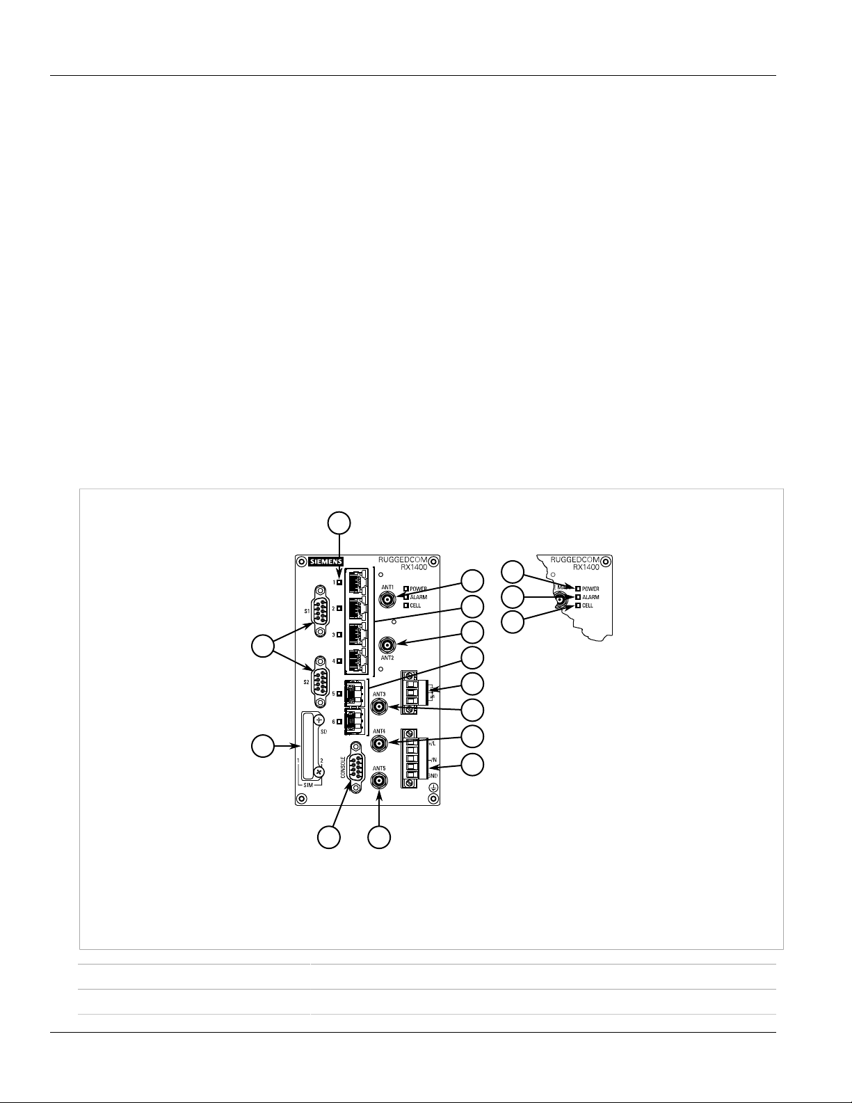
The RUGGEDCOM RX1400 features various ports, controls and indicator LEDs on the front panel for connecting,
configuring and troubleshooting the device.
1.Serial Ports 2.Access Plate 3.Port Status LEDs 4.ANT1 Port 5.Fast Ethernet Ports 6.ANT2 Port 7.SFP Transceiver Ports
8.Failsafe Alarm Relay 9.ANT3 Port 10.ANT4 Port 11.Power Supply Terminal Block 12.RS232 Serial Console Port (DB9) 13.ANT5
Port 14.POWER LED 15.ALARM LED 16.CELL LED
POWER LED Illuminates when power is being supplied to the device.
ALARM LED Illuminates when an alarm condition exists.
Figure1:RUGGEDCOM RX1400
2 Description
Page 13

RUGGEDCOM RX1400
Installation Guide
CELL LED Indicates when the cellular modem is connected to the network.
• Solid = Activity
• Off = No activity
Port Status LEDs Indicate the status of each port:
• Solid = Link
• Blinking = Activity
• Off = No link/activity
Access Plate The removable access plate provides access to the Micro SD card and SIM card slots.
• Use a Micro SD card to store the firmware and configuration for the device
• Use a single or dual (recommended) SIM cards to connect to an LTE network
Chapter 1
Introduction
RS232 Serial Console Port The serial console port is for interfacing directly with the device and accessing initial
management functions. For information about connecting to the device via the serial
console port, refer to Section2.11, “Connecting to the Device”.
ANT Ports SMA ports for connecting to an LTE network or Global Navigation Satellite System (GNSS).
For more information, refer to:
• Section2.6, “Connecting the Antennas”
• Section4.5, “Cellular Modem Specifications”
Failsafe Alarm Relay Latches to default state when a power disruption or other alarm condition occurs. For more
information, refer to:
• Section2.9, “Connecting the Failsafe Alarm Relay”
• Section4.2, “Failsafe Alarm Relay Specifications”
Power Supply Terminal Block A pluggable terminal block. For more information, refer to:
• Section2.10, “Connecting Power”
• Section4.1, “Power Supply Specifications”
Description 3
Page 14

Chapter 1
Introduction
RUGGEDCOM RX1400
Installation Guide
4 Description
Page 15
RUGGEDCOM RX1400
Installation Guide
Installing the Device
This chapter describes how to install the device, including mounting the device, connecting power, and
connecting the device to the network.
DANGER!
Electrocution hazard – risk of serious personal injury and/or damage to equipment. Before performing
any maintenance tasks, make sure all power to the device has been disconnected and wait
approximately two minutes for any remaining energy to dissipate.
WARNING!
Radiation hazard – risk of serious personal injury. This product contains a laser system and is classified
as a CLASS 1 LASER PRODUCT. Use of controls or adjustments or performance of procedures other
than those specified herein may result in hazardous radiation exposure.
Installing the Device
Chapter 2
WARNING!
Radiation hazard – risk of Radio Frequency (RF) exposure. This device is compliant with the
requirements set forth in FCC 47 CFR, section 1.1307, addressing Radio Frequency (RF) exposure from
radio frequency base stations, as defined in FCC OET Bulletin 65 [http://transition.fcc.gov/Bureaus/
Engineering_Technology/Documents/bulletins/oet65/oet65.pdf]. The emitted radiation should be as
little as possible. To achieve minimum RF exposure, install the device when it is configured not to
transmit and set it to operational mode remotely, rather than having a technician enable transmission
on-site. For maintenance of the device, or other operations which require RF exposure, the exposure
should be minimized in time and according to the regulations set forth by the country of installation or
the Federal Communications Commission (FCC).
IMPORTANT!
This product contains no user-serviceable parts. Attempted service by unauthorized personnel shall
render all warranties null and void.
Changes or modifications not expressly approved by Siemens Canada Ltd could invalidate
specifications, test results, and agency approvals, and void the user's authority to operate the
equipment.
IMPORTANT!
This product should be installed in a restricted access location where access can only be gained by
authorized personnel who have been informed of the restrictions and any precautions that must be
taken. Access must only be possible through the use of a tool, lock and key, or other means of security,
and controlled by the authority responsible for the location.
CONTENTS
• Section2.1, “General Procedure”
• Section2.2, “Required Tools and Materials”
• Section2.3, “Cabling Recommendations”
5
Page 16
Chapter 2
Installing the Device
RUGGEDCOM RX1400
Installation Guide
• Section2.4, “Installing the Device in Hazardous Locations”
• Section2.5, “Mounting the Device”
• Section2.6, “Connecting the Antennas”
• Section2.7, “Installing the SIM Cards”
• Section2.8, “Inserting/Removing the MicroSD Card”
• Section2.9, “Connecting the Failsafe Alarm Relay”
• Section2.10, “Connecting Power”
• Section2.11, “Connecting to the Device”
• Section2.12, “Configuring the Device”
Section2.1
General Procedure
The general procedure for installing the device is as follows:
1. Review the relevant certification information for any regulatory requirements. For more information, refer to
Section6.1, “Approvals”.
2. Mount the device.
3. Connect an antenna or antennas.
4. For LTE antennas only, install SIM cards.
5. Connect the failsafe alarm relay.
6. Connect power to the device and ground the device to safety Earth.
7. Connect the device to the network.
8. Configure the device.
Section2.2
Required Tools and Materials
The following tools and materials are required to install the RUGGEDCOM RX1400:
Tool/Material Available For Purchase From Siemens
WLAN, LTE and/or GPS antennas
Antenna N-connect and/or SMA cables
AC/DC power cord (16 AWG)
Lightning protector
Shielded coaxial cables
SIM card(s) provided by the network carrier
Flathead screwdriver for mounting the device to a DIN rail
Phillips screwdriver for mounting the device to a rack or panel
ü
ü
û
û
û
û
û
û
a
6 General Procedure
Page 17
RUGGEDCOM RX1400
Installation Guide
Installing the Device
Chapter 2
Tool/Material Available For Purchase From Siemens
Braided or equivalent ground wire for grounding the device
a
For more information, contact a Siemens Sales representative.
Section2.3
û
Cabling Recommendations
Siemens recommends using SIMATIC NET industrial Ethernet shielded cables for all Ethernet ports.
CONTENTS
• Section2.3.1, “Protection On Twisted-Pair Data Ports”
• Section2.3.2, “Gigabit Ethernet 1000Base-TX Cabling Recommendations”
Section2.3.1
Protection On Twisted-Pair Data Ports
All copper Ethernet ports on RUGGEDCOM products include transient suppression circuitry to protect against
damage from electrical transients and conform with IEC 61850-3 and IEEE 1613 Class 1 standards. This means
that during a transient electrical event, communications errors or interruptions may occur, but recovery is
automatic.
Siemens also does not recommend using copper Ethernet ports to interface with devices in the field across
distances that could produce high levels of ground potential rise (i.e. greater than 2500 V), during line-to-ground
fault conditions.
a
Section2.3.2
Gigabit Ethernet 1000Base-TX Cabling Recommendations
The IEEE 802.3ab Gigabit Ethernet standard defines 1000 Mbit/s Ethernet communications over distances of up
to 100 m (328 ft) using all 4 pairs in category 5 (or higher) balanced, unshielded twisted-pair cabling. For wiring
guidelines, system designers and integrators should refer to the Telecommunications Industry Association (TIA)
TIA/EIA-568-A wiring standard that characterizes minimum cabling performance specifications required for proper
Gigabit Ethernet operation. For reliable, error-free data communication, new and pre-existing communication
paths should be verified for TIA/EIA-568-A compliance.
The following table summarizes the relevant cabling standards:
Cabling Category
< 5 No New wiring infrastructure required.
5 Yes Verify TIA/EIA-568-A compliance.
5e Yes No action required. New installations should be designed with Category 5e or higher.
6 Yes No action required.
> 6 Yes Connector and wiring standards to be determined.
Cabling Recommendations 7
1000Base-
TX Compliant
Required Action
Page 18
Chapter 2
Installing the Device
Follow these recommendations for copper data cabling in high electrical noise environments:
• Data cable lengths should be as short as possible, preferably 3 m (10 ft) in length. Copper data cables should
not be used for inter-building communications.
• Power and data cables should not be run in parallel for long distances, and should be installed in separate
conduits. Power and data cables should intersect at 90° angles when necessary to reduce inductive coupling.
Section2.4
RUGGEDCOM RX1400
Installation Guide
Installing the Device in Hazardous Locations
The RUGGEDCOM RX1400 is designed to comply with the safety standards for Class I, Division 2, Zone 2 hazardous
locations where concentrations of flammable gases, vapors or liquids may be present, as opposed to normal
operating environments.
Special Conditions for Safe Use
Installation and use of the device in a hazardous location must meet the following special conditions for safe use:
• The equipment shall be installed in an enclosure that provides an ingress protection rating of not less than IP54
according to CSA/UL/IEC/EN 60079-0 and CSA/UL/IEC/EN 60079-7 or CSA/UL/IEC/EN 60079-15. The enclosure
shall have a minimum ambient temperature range of -40 to 95 °C (-40 to 203 °F).
• The equipment shall be used in an area of not more than pollution degree 2, as defined in IEC/EN 60664-1.
• Transient protection shall be provided that is set at a level not exceeding 140% of the peak rated voltage value
at the supply terminals to the equipment.
• The microSD card slot and serial console port shall only be used in the safe area.
• The equipment must be appropriately connected to safety Earth upon installation.
NOTE
For further details of the device's compliance with Class I, Division 2, Zone 2 standards, refer to
Section6.1, “Approvals”.
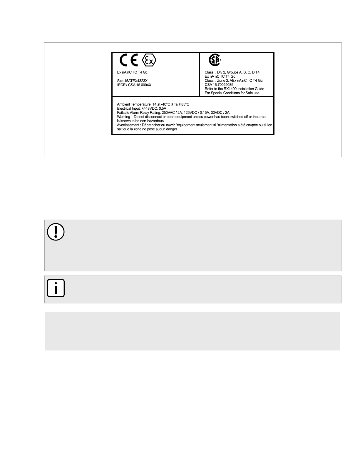
Sample Hazardous Location Label
The following is an example of the RUGGEDCOM RX1400 hazardous location label:
8 Installing the Device in Hazardous Locations
Page 19
RUGGEDCOM RX1400
II 3 G
C US
Installation Guide
Figure2:Compliance Label (Example)
Section2.5
Mounting the Device
Installing the Device
Chapter 2
The RUGGEDCOM RX1400 is designed for maximum mounting and display flexibility. It can be equipped with
brackets that allow it to be installed in a 48 cm (19 in) rack, 35 mm (1.4 in) DIN rail, or directly on a panel.
IMPORTANT!
Heat generated by the device is channeled outwards to the enclosure. As such, it is recommended that
2.5 cm (1 in) of space be maintained on all open sides of the device to allow for some convectional
airflow.
Forced airflow is not required. However, any increase in airflow will result in a reduction of ambient
temperature and improve the long-term reliability of all equipment mounted in the rack space.
NOTE
For detailed dimensions of the device with either rack, DIN rail or panel hardware installed, refer to
Chapter5, Dimension Drawings.
CONTENTS
• Section2.5.1, “Mounting the Device to a Rack”
• Section2.5.2, “Mounting the Device on a DIN Rail”
• Section2.5.3, “Mounting the Device to a Panel”
Section2.5.1
Mounting the Device to a Rack
For rack mount installations, the RUGGEDCOM RX1400 can be equipped with rack mount adapters pre-installed on
the chassis.
Mounting the Device 9
Page 20

Chapter 2
1 12
Installing the Device
CAUTION!
Electrical/mechanical hazard – risk of damage to the device. Before installing the device in a rack,
make sure of the following:
• When installing the device in a closed or multi-device rack, be aware the operating ambient
• Make sure each device in the rack is separated by at least one rack-unit of space, or 44 mm (1.75 in),
• Do not exceed the maximum number of devices or weight restrictions specified by the rack
• Do not overload the supply circuit. Refer to the over-current protection and power supply ratings
• Make sure the rack and all devices have a proper ground-to-Earth connection. Pay particular
RUGGEDCOM RX1400
Installation Guide
temperature of the rack may be higher than the ambient temperature of the room. Make sure the
rack is installed in a suitable environment that can withstand the maximum ambient temperature
generated by the rack.
to promote convectional airflow. Forced airflow is not required. However, any increase in airflow will
result in a reduction of ambient temperature and improve the long-term reliability of all equipment
mounted in the rack space.
manufacturer.
specified by the rack manufacturer.
attention to power supply connections other than direct connections to the branch circuit (e.g. power
strips).
To secure the device to a standard 48 cm (19 in) rack, do the following:
1. Make sure the rack mount adapters are installed.
Figure3:Rack Mount Adapters
1.Rack Mount Adapter 2.RUGGEDCOM RX1400
2. Insert the assembly into the rack.
3. Secure the adapters to the rack using the supplied hardware.
Section2.5.2
Mounting the Device on a DIN Rail
For DIN rail installations, the RX1400 can be equipped with a DIN rail bracket pre-installed on the back of the
chassis. The bracket allows the device to be slid onto a standard 35 mm (1.4 in) DIN rail.
To mount the device to a DIN rail, do the following:
1. Align the slot in the bracket with the DIN rail.
10 Mounting the Device on a DIN Rail
Page 21

RUGGEDCOM RX1400
1
1
2
Installation Guide
Figure4:DIN Rail Mounting
1.DIN Rail 2.DIN Rail Bracket
Installing the Device
Chapter 2
2. Pull the release on the bracket down and slide the device onto the DIN rail. Let go of the release to lock the
device in position. If access to the release is limited, use a slotted screwdriver or a similar tool to reach the
release.
Section2.5.3
Mounting the Device to a Panel
For panel installations, the RUGGEDCOM RX1400 can be equipped with panel adapters pre-installed on each side
of the chassis. The adapters allow the device to be attached to a panel using screws.
To mount the device to a panel, do the following:
1. Place the device against the panel and align the adapters with the mounting holes.
Mounting the Device to a Panel 11
Page 22

Chapter 2
2
1
2
1
Installing the Device
Figure5:Panel Mounting
1.Screw 2.Panel Adapter
2. Install the supplied screws to secure the adapters to the panel.
RUGGEDCOM RX1400
Installation Guide
Section2.6
Connecting the Antennas
The RUGGEDCOM RX1400 can be connected to external antennas for access to wireless networks. For increased
signal coverage and improved performance, antennas are intended to be installed in a remote location separate
from the RUGGEDCOM RX1400.
IMPORTANT!
The antenna installation must be as per Article 810 of the National Electric Code (NEC). Specifically, the
grounding conductor must not be less than 10 AWG (Cu). The scheme should be either:
• In accordance with UL 96 and 96A Lightning Protection Components and Installation Requirements
for Lightning Protection Systems (LPS)
• Tested in accordance with UL 50 and UL 497
NOTE
For technical specifications, refer to Section4.5, “Cellular Modem Specifications”.
CONTENTS
• Section2.6.1, “Available Antennas”
• Section2.6.2, “Connecting LTE Antennas”
• Section2.6.3, “Connecting a GPS Antenna”
• Section2.6.4, “Connecting WLAN Antennas”
12 Connecting the Antennas
Page 23

RUGGEDCOM RX1400
Installation Guide
Section2.6.1
Available Antennas
The RUGGEDCOM RX1400 supports the following antennas.
Cellular, GPS and WLAN Antennas
Installing the Device
Chapter 2
Antenna Type
ANT1995-4MM Omni-
Directional
Operating
Frequency
0.7 to 1.0
1.7 to 2.7
Cellular and GPS Antennas
Antenna Type
Directional
Directional
Operating
Frequency
GPS Antennas
(GHz)
2.4
5.0
(GHz)
0.7ANT1096-4ME Omni-
2.7
0.7ANT1096-4MA Omni-
2.7
Gain (dBi) Article Number Reference
2.5
3.0 to 4.0
Gain (dBi) Article Number Reference
3.0 6GK6000-8NT01-1AA0 https://support.industry.siemens.com/cs/
3.0 6GK6000-8NT01-0AA0 https://support.industry.siemens.com/cs/
6GK6000-8NS01-1AA0 https://support.industry.siemens.com/cs/
ww/en/view/109748485
ww/en/view/109477766
me/en/view/109477585
Antenna Type
ANT1390-4ML Omni-
Directional
Operating
Frequency
(GHz)
1.5 3.0 6GK6000-8NT01-0AA0 https://support.industry.siemens.com/cs/
Gain (dBi) Article Number Reference
ww/en/view/109477767
WLAN Antennas
Antenna Type
ANT792-4DN Omni-
Directional
ANT792-6MN Omni-
Directional
ANT792-8DN Directional 2.4 14.0 6GK5792-8DN00-0AA6 https://support.industry.siemens.com/cs/
Available Antennas 13
Operating
Frequency
(GHz)
2.4 4.0 6GK5792-4DN00-0AA6 —
2.4 6.0 6GK5792-6MN00-0AA6 https://support.industry.siemens.com/cs/
Gain (dBi) Article Number Reference
ww/en/view/26210199
ww/en/view/26229510
Page 24

Chapter 2
Installing the Device
RUGGEDCOM RX1400
Installation Guide
Antenna Type
ANT793-4MN Omni-
Directional
ANT793-6DG
ANT793-6DT
b
Directional 5.0 9.0 6GK5793-6DG00-0AA0 https://support.industry.siemens.com/cs/
bc
Omni-
Directional
ANT793-6MN Omni-
Directional
ANT793-8DJ
ANT793-8DP
be
Directional 5.0 18.0
bc
Directional 5.0 13.5
Directional
Directional
Directional
Operating
Frequency
Gain (dBi) Article Number Reference
(GHz)
5.0 6.0 6GK5792-4MN00-0AA6 —
ww/en/view/60509676
5.0 8.0
d
6GK5793-6DT00-0AA0 https://support.industry.siemens.com/cs/
ww/en/view/60510334
5.0 5.0 6GK5793-6MN00-0AA6 https://support.industry.siemens.com/cs/
ww/en/view/26228205
f
6GK5793-8DJ00-0AA0 https://support.industry.siemens.com/cs/
ww/en/view/60509959
g
6GK5793-8DP00-0AA0 https://support.industry.siemens.com/cs/
ww/en/view/89534905
2.4 3.0ANT795-4MA Omni-
6GK5795-4MA00-0AA0 https://support.industry.siemens.com/cs/
ww/en/view/61199227
5.0 5.0
2.4 3.0ANT795-4MC Omni-
6GK5795-4MC00-0AA0 https://support.industry.siemens.com/cs/
ww/en/view/61199227
5.0 5.0
2.4 3.0ANT795-4MD Omni-
6GK5795-4MD00-0AA0 https://support.industry.siemens.com/cs/
ww/en/view/61199227
5.0 5.0
2.4 2.0ANT795-4MX Omni-
6GK5795-4MX00-0AA0 https://support.industry.siemens.com/cs/
Directional
5.0 2.5
2.4ANT795-6DC Directional
b
5.0
c
Directional 2.4 6.0ANT795-6MN
Omni-
5.0
b
9.0 6GK5795-6DC00-0AA0 https://support.industry.siemens.com/cs/
6GK5795-6MN10-0AA6 https://support.industry.siemens.com/cs/
d
8.0
Directional
c
Directional 2.4 5.0ANT795-6MT
Omni-
5.0
b
7.0
h
6GK5795-6MT00-0AA0 https://support.industry.siemens.com/cs/
Directional
b
Not for use in Canada.
c
Must always be used with a 5 m (16 ft) cable (6X1875-5CH50).
d
Total gain is 3.6 dBi when connected via a 5 m (16 ft) cable (6X1875-5CH50) with a 4.4 dB loss.
e
Must always be used with a 10 m (33 ft) cable (6X1875-5CN10).
f
Total gain is 9.2 dBi when connected via a 10 m (33 ft) cable (6X1875-5CN10) with an 8.8 dB loss.
g
Total gain is 9.1 dBi when connected via a 5 m (16 ft) cable (6X1875-5CH50) with a 4.4 dB loss.
h
Total gain is 2.6 dBi when connected via a 5 m (16 ft) cable (6X1875-5CH50) with a 4.4 dB loss.
ww/en/view/102325861
ww/en/view/60510336
ww/en/view/26536615
ww/en/view/60510908
14 Available Antennas
Page 25

RUGGEDCOM RX1400
Installation Guide
Section2.6.2
Installing the Device
Connecting LTE Antennas
Install a single 4G LTE (Long Term Evolution) antenna for Single-Input Single-Output (SISO) or dual antennas for
Multiple-Input Multiple-Output (MIMO).
To install an LTE antenna, do the following:
WARNING!
Radiation hazard – risk of Radio Frequency (RF) exposure. Antennas must be placed at a distance of
at least 35 cm (13.8 in) from all persons during normal operation. The antennas used for this product
must not be located or operating in conjunction with any other antenna or transmitter, except in
accordance with FCC multi-transmitter evaluation procedures.
CAUTION!
Configuration hazard – risk of reduced performance. Each antenna and connecting cable must have a
nominal impedance of 50 Ω with a return loss of better than 10 dB across each frequency band. If the
nominal impedance is different, Radio Frequency (RF) performance will be reduced.
IMPORTANT!
The antenna installation must be as per Article 810 of the National Electric Code (NEC). Specifically, the
grounding conductor must not be less than 10 AWG (Cu). The scheme should be either:
• In accordance with UL 96 and 96A Lightning Protection Components and Installation Requirements
for Lightning Protection Systems (LPS)
• Tested in accordance with UL 50 and UL 497
Chapter 2
IMPORTANT!
A Radio Frequency (RF) site survey is recommended prior to any installation to help determine the best
location for the LTE antennas. For assistance, contact a Siemens Sales representative.
IMPORTANT!
The cellular modem supports SISO (Single Input Single Output) and MIMO (Multiple Input Multiple
Output) modes. At minimum, a single antenna connected to the LTE MAIN port is required for SISO
mode and to support lower generation wireless standards, such as GSM or EDGE. A separate diversity
(secondary) antenna is required for MIMO performance.
IMPORTANT!
For mobile and fixed operating configurations, in accordance with R&TTE Directive 1999/5/EC, the
maximum antenna gain is 3 dBi for 900 MHz, 1800 MHz, 2100 MHz and 2600 MHz.
IMPORTANT!
For mobile and fixed operating configurations, in accordance with FCC 47 CFR, section 2.1091, the
antenna gain, including cable loss must not exceed:
• 6.0 dBi at 700 MHz
• 3.0 dBi at 800/850 MHz
• 6.0 dBi at 1700 MHz
• 3.0 dBi at 1900 MHz
Connecting LTE Antennas 15
Page 26

Chapter 2
4
1
1
3
3
5
2
6
5
Installing the Device
Installation Guide
Under no conditions may an antenna gain be used that would exceed the ERP and/or EIRP power limits
specified in FCC 47 CFR Parts 22, 24, 27 and 90.
NOTE
For technical specifications, refer to Section4.5, “Cellular Modem Specifications”.
NOTE
A specific brand of antenna is not specified.
1. Mount the antenna to a pole or wall in an area that provides good signal coverage and is away from any
signal noise emanating from other communications equipment.
IMPORTANT!
MIMO is not certified for use in the Republic of Korea (South Korea).
2. Using shielded coaxial cables, connect the antenna to either the ANT1 (SISO) or ANT5 (MIMO) port on the
device. Make sure the cable is routed away from any noise sources, such as Switch-Mode Power Supplies
(SMPS).
If needed, install a lightning protect between the antenna and the device.
RUGGEDCOM RX1400
Figure6:Antenna and Lightning Protector Assembly (Optional)
1.Drain Wire 2.RUGGEDCOM RX1400 3.Shielded Coaxial Cable 4.Lightning Protector 5.Ground Wire 6.LTE Antenna
Section2.6.3
Connecting a GPS Antenna
For increased signal coverage and improved performance, the GPS antenna is intended to be installed in a remote
location separate from the RX1400. The signals received from the GPS satellite network are at a frequency of
1575.42 MHz. The GPS antenna must therefore have a clear view of the sky to receive the low power signals and
track the maximum number of satellites. Structures, such as rooftops, that are clear of obstructions and have a
clear view of the horizon are ideal.
16 Connecting a GPS Antenna
Page 27

RUGGEDCOM RX1400
Installation Guide
Installing the Device
IMPORTANT!
A site survey is recommended prior to any installation to help determine the best location for the GPS
antenna. For assistance, contact a Siemens Sales representative.
IMPORTANT!
Although it is impossible to protect the antenna from a direct lightning strike, the antenna and
connected components can be protected from secondary effects through site selection and by installing
protection devices.
Install the antenna at least 15 m (49 ft) away from and lower than any structures that attract
lightning. GPS antenna damage is usually not the result of a direct lightning strike, but due to high
currents induced by the effects of a lightning strike on a nearby structure. Lightning arrestors should
also be installed in the antenna line to protect the receiver and connected devices. If a lightning
arrestor is installed, it is important to make sure it has a low impedance path to ground.
To promote signal reception and avoid signal saturation at the receiver input, the overall GPS system requires a
relative gain between 5 and 18 dBi.
Use only low loss, 50 Ω coaxial cabling when connecting the GPS and any other optional components to the
RX1400.
NOTE
Using any length of coaxial cable will add some time delay to the GPS signal, which degrades the
accuracy of the calculated time and position. The time delay is dependent on the type of dielectric
material in the cable and ranges from 1 to 2 ns/ft. The table below gives some examples of the delay
that can be expected based on the dielectric type.
Chapter 2
Dielectric Type Time Delay (ns/ft) Propagation Velocity (% of c)
Solid Polyethylene (PE) 1.54 65.9
Foam Polyethylene (FE) 1.27 80.0
Foam Polystyrene (FS) 1.12 91.0
Air Space Polyethylene (ASP) 1.15 to 1.21 84 to 88
Solid Teflon (ST) 1.46 69.4
Air Space Teflon (AST) 1.13 to 1.20 85 to 90
To connect a GPS antenna, do the following:
1. Mount the antenna to a pole or wall in an area that provides good signal coverage and is away from any
signal noise emanating from other communications equipment. Make sure 90° of the sky is visible to the
antenna.
2. If required, connect the optional lightning arrestor, line amplifier or bandpass filter to the antenna.
Connecting a GPS Antenna 17
Page 28

Chapter 2
4
1
1
3
3
5
2
6
5
Installing the Device
Figure7:Antenna and Lightning Protector Assembly (Optional)
1.Drain Wire 2.RUGGEDCOM RX1400 3.Shielded Coaxial Cable 4.Lightning Protector, Line Amplifier or Bandpass Filter
5.Ground Wire 6.GPS Antenna
3. Using shielded coaxial cables, connect the antenna assembly to the ANT2 port on the device.
RUGGEDCOM RX1400
Installation Guide
Section2.6.4
Connecting WLAN Antennas
Install a single WLAN antenna for Single-Input Single-Output (SISO) or dual antennas for Multiple-Input MultipleOutput (MIMO).
To install a WLAN antenna, do the following:
1. Select an appropriate antenna. For a list of available WLAN antennas, refer to Section2.6.1, “Available
Antennas”.
2. Mount the antenna to a pole or wall in an area that provides good signal coverage and is away from any
signal noise emanating from other communications equipment.
3. Using shielded coaxial cables, connect the antenna to either the ANT3 (SISO) or ANT4 (MIMO) port on the
device. Make sure the cable is routed away from any noise sources, such as Switch-Mode Power Supplies
(SMPS).
If needed, install a lightning protect between the antenna and the device.
18 Connecting WLAN Antennas
Page 29

RUGGEDCOM RX1400
4
1
1
3
3
5
2
6
5
1
3
2
Installation Guide
Figure8:Antenna and Lightning Protector Assembly (Optional)
1.Drain Wire 2.RUGGEDCOM RX1400 3.Shielded Coaxial Cable 4.Lightning Protector 5.Ground Wire 6.WLAN Antenna
Section2.7
Installing the Device
Chapter 2
Installing the SIM Cards
The RUGGEDCOM RX1400 supports dual micro-SIM cards for the LTE modem to provide a fail-over mechanism
should one of the SIM cards lose connectivity with the network.
To install micro-SIM cards from a regional cellular carrier, do the following:
CAUTION!
Static electricity hazard – risk of damage to equipment. Take appropriate anti-static precautions before
accessing the SIM cards.
1. Remove the SIM card access panel.
Figure9:Accessing the SIM Cards
1.Access Panel 2.Secondary Micro-SIM Card 3.Primary Micro-SIM Card
2. Insert the SIM cards into the slots. Slot 1 is for the primary SIM card and slot 2 is for the secondary (backup)
SIM card.
3. Close the access panel and secure it with the two screws.
Installing the SIM Cards 19
Page 30

Chapter 2
2
1
Installing the Device
RUGGEDCOM RX1400
Installation Guide
4. Once the device is fully installed, activate the micro-SIM cards for the LTE modem. For more information, refer
to the RUGGEDCOM ROX II User Guide for the RUGGEDCOM RX1400.
Section2.8
Inserting/Removing the MicroSD Card
The RUGGEDCOM RX1400 accepts a microSD card for storing configuration files and/or software updates.
CAUTION!
Configuration hazard – risk of data loss. The microSD card must not be removed or replaced during
normal operation of the device. Make sure the device is powered down before removing or inserting
the card.
CAUTION!
Mechanical/electrical hazard – risk of damage to the microSD card.
• Do not expose the microSD card to extreme temperatures or humidity.
• Do not expose the microSD card to large magnetic or static electric fields.
• Do not bend or drop the microSD card.
CAUTION!
Security hazard – risk of unauthorized access and/or exploitation. Make sure to remove the microSD
card before decommissioning the device or sending the device to a third-party.
To insert or remove a microSD card, do the following:
1. Power down the device.
2. Disconnect all network, alarm and console cables.
3. Unscrew the retention screw and remove the access plate.
Figure10:Inserting/Removing a MicroSD Card
1.MicroSD Card 2.Access Plate
4. Without touching the contacts on the card, insert or remove the microSD card.
5. Install the access plate and finger-tighten the retention screw.
6. Power up the device.
20 Inserting/Removing the MicroSD Card
Page 31

RUGGEDCOM RX1400
2 31
Installation Guide
Section2.9
Installing the Device
Connecting the Failsafe Alarm Relay
The failsafe relay can be configured to latch based on alarm conditions. The NO (Normally Open) contact is closed
when the unit is powered and there are no active alarms. If the device is not powered or if an active alarm is
configured, the relay opens the NO contact and closes the NC (Normally Closed) contact.
NOTE
Control of the failsafe relay output is configurable through ROX II. One common application for this
relay is to signal an alarm if a power failure occurs. For more information, refer to the ROX II User
Guide for the RUGGEDCOM RX1400.
The following shows the proper relay connections.
Chapter 2
Figure11:Failsafe Alarm Relay Wiring
1.Normally Closed 2.Common 3.Normally Open
Section2.10
Connecting Power
The RUGGEDCOM RX1400 supports a single integrated high AC/DC or low DC power supply.
IMPORTANT!
Before installing the device, note the following:
• An appropriately rated AC or DC circuit breaker must be installed.
• Use only #16 gage copper wiring when connecting terminal blocks.
• Equipment must be installed according to applicable local wiring codes and standards.
CONTENTS
• Section2.10.1, “Connecting High AC/DC Power”
• Section2.10.2, “Connecting Low DC Power”
Connecting the Failsafe Alarm Relay 21
Page 32

Chapter 2
5
1
2
3
4
Installing the Device
Section2.10.1
Connecting High AC/DC Power
To connect a high AC/DC power supply to the device, do the following:
CAUTION!
Electrical hazard – risk of damage to equipment. Do not connect AC power cables to terminals for DC
power. Damage to the power supply may occur.
1. Connect the power supply terminal block to the device.
RUGGEDCOM RX1400
Installation Guide
Figure12:Terminal Block Wiring
1.Surge Ground Terminal 2.Negative/Neutral (-/N) Terminal 3.Positive/Live (+/L) Terminal 4.Braided Ground Cable 5.Power
Supply Terminal Block
2. Connect the positive wire from the power source to the positive/live (+/L) terminal on the terminal block.
3. Connect the negative wire from the power source to the negative/neutral (-/N) terminal on the terminal block.
4. Using a braided wire or other appropriate grounding wire, connect the surge ground terminal to the chassis
ground connection. The surge ground terminal is used as the ground conductor for all surge and transient
suppression circuitry internal to the unit.
5. Connect the ground terminal on the power source to the chassis ground terminal on the device.
Section2.10.2
Connecting Low DC Power
To connect a low DC power supply to the device, do the following:
22 Connecting High AC/DC Power
Page 33

RUGGEDCOM RX1400
1
2
3
4
5
Installation Guide
1. Connect the power supply terminal block to the device.
Installing the Device
Chapter 2
Figure13:Terminal Block Wiring
1.Surge Ground Terminal 2.Negative Terminal 3.Positive Terminal 4.Braided Ground Cable 5.Power Supply Terminal Block
2. Connect the positive wire from the power source to the positive terminal on the terminal block.
3. Connect the negative wire from the power source to the negative terminal on the terminal block.
4. Using a braided wire or other appropriate grounding wire, connect the surge ground terminal to the chassis
ground connection. The surge ground terminal is used as the ground conductor for all surge and transient
suppression circuitry internal to the unit.
5. Connect the ground terminal on the power source to the chassis ground terminal on the device.
Section2.11
Connecting to the Device
The following describes the various methods for accessing the RUGGEDCOM ROX II console and Web interfaces
on the device. For more detailed instructions, refer to the RUGGEDCOM ROX II User Guide for the RUGGEDCOM
RX1400.
Serial Console Port
Connect a PC or terminal directly to the serial console port to access the boot-time control and RUGGEDCOM ROX
II console interface.
IMPORTANT!
The serial console port is intended to be used only as temporary connections during initial
configuration or troubleshooting.
Connecting to the Device 23
Page 34

Chapter 2
5
1
69
Installing the Device
Installation Guide
The serial console port implements RS-232 on a female DB9 connector. The following is the pin-out for the port:
Pin Name
1 Reserved (Do Not Connect)
2 Output Signal
3 Input Signal
4 Reserved (Do Not Connect)
5 Ground
6 Reserved (Do Not Connect)
RUGGEDCOM RX1400
Figure14:Serial DB9 Console Port
7 Reserved (Do Not Connect)
8 Reserved (Do Not Connect)
9 Reserved (Do Not Connect)
For information about how to connect to the device via the serial console port, refer to the RUGGEDCOM ROX II CLI
User Guide for the RUGGEDCOM RX1400.
Communication Ports
Connect any of the available Ethernet ports on the device to a management switch and access the RUGGEDCOM
ROX II console and Web interfaces via the device's IP address. The factory default IP address for the RUGGEDCOM
RX1400 is https://192.168.0.2.
For more information about available ports, refer to Chapter3, Communication Ports.
Section2.12
Configuring the Device
Once the device is installed and connected to the network, it must be configured. All configuration management
is done via the RUGGEDCOM ROX II interface. For more information about configuring the device, refer to the
RUGGEDCOM ROX II User Guide associated with the installed software release.
24 Configuring the Device
Page 35

RUGGEDCOM RX1400
1
5
4
2
6
7
8
9
3
Installation Guide
Communication Ports
Communication Ports
The RUGGEDCOM RX1400 can be equipped with various types of communication ports to enhance its abilities and
performance.
Chapter 3
Figure15:Port Assignment
1.Serial Ports 2.Access Plate 3.ANT1 Port 4.Fast Ethernet Ports 5.ANT2 Port 6.SFP Transceiver Ports 7.ANT3 Port 8.ANT4
Port 9.ANT5 Port
NOTE
For information about the LTE MAIN, LTE MIMO or GPS ports and the cellular modem, refer to
Section4.5, “Cellular Modem Specifications”.
CONTENTS
• Section3.1, “Fast Ethernet Ports”
• Section3.2, “SFP Transceivers”
• Section3.3, “Serial Ports”
Section3.1
Fast Ethernet Ports
The RUGGEDCOM RX1400 features four 10/100Base-TX fast Ethernet (FE) ports with RJ45 connectors. The RJ45
connectors are directly connected to the chassis ground on the device and can accept CAT-5 shielded twisted-pair
(STP) cables.
Fast Ethernet Ports 25
Page 36

Chapter 3
8 1
Communication Ports
For technical specifications, refer to Section4.3, “Fast Ethernet Port Specifications”.
Each port features an LED that indicates its link state.
State Description
Green (Solid) Link established
Green (Blinking) Activity
Off No link detected
The following are the pin-out descriptions for the RJ45 connectors:
Pin 10/100Base-TX Description
1 RX+ Receive Data+
2 RX- Receive Data-
3 TX+ Transmit Data+
RUGGEDCOM RX1400
Installation Guide
Figure16:RJ45 Ethernet Port Pin Configuration
Section3.2
4 Reserved (Do Not Connect)
5 Reserved (Do Not Connect)
6 TX- Transmit Data-
7 Reserved (Do Not Connect)
8 Reserved (Do Not Connect)
SFP Transceivers
The RUGGEDCOM RX1400 features two Small Form-Factor Pluggable (SFP) transceiver sockets, which are
compatible with a wide array of SFP transceivers available from Siemens.
LEDs
Each socket features an LED that indicates its link state.
State Description
Green (Solid) Link established
Green (Blinking) Activity
Off No link detected
Compatible SFP Transceivers
The following SFP transceivers are compatible with the RUGGEDCOM RX1400. For more information, including
installation/removal instructions and ordering information, refer to the RUGGEDCOM SFP Transceiver Catalog
[https://support.industry.siemens.com/cs/ca/en/view/109482309].
26 SFP Transceivers
Page 37

RUGGEDCOM RX1400
5
1
69
Installation Guide
Communication Ports
Chapter 3
IMPORTANT!
Only use SFP transceivers approved by Siemens for RUGGEDCOM products. Siemens accepts no liability
as a result of performance issues related in whole or in part to third-party components.
SFP Transceiver Order Code
RUGGEDCOM SFP1121-1FX2A 6GK6000-8FE50-0AA0 100 MM 2
RUGGEDCOM SFP1132-1BX10R 6GK6000-8FB51-0AA0 1000 SM 10
RUGGEDCOM SFP1132-1BX10T 6GK6000-8FB52-0AA0 1000 SM 10
RUGGEDCOM SFP1132-1BX40R 6GK6000-8FB53-0AA0 1000 SM 40
RUGGEDCOM SFP1132-1BX40T 6GK6000-8FB54-0AA0 1000 SM 40
RUGGEDCOM SFP1122-1SX 6GK6000-8FG51-0AA0 1000 MM 0.5
RUGGEDCOM SFP1132-1LX10 6GK6000-8FG52-0AA0 1000 SM 10
RUGGEDCOM SFP1132-1LX25 6GK6000-8FG53-0AA0 1000 SM 25
RUGGEDCOM SFP1132-1LX40 6GK6000-8FG57-0AA0 1000 SM 40
RUGGEDCOM SFP1132-1LX70 6GK6000-8FG54-0AA0 1000 SM 70
RUGGEDCOM SFP1132-1LX100 6GK6000-8FG55-0AA0 1000 SM 100
a
MM = Multi-Mode, SM = Single-Mode
Speed
(Mbit/s)
Mode
a
Section3.3
Serial Ports
Nominal Distance (km)
The RUGGEDCOM RX1400 supports two serial ports with female DB9 connectors, which can be run in RS-232,
RS-485 or RS-422 mode. For technical specifications, refer to Section4.4, “Serial Port Specifications”.
The following is the pin-out description for DB9 serial ports:
Serial DB9 Port
Pin
1 Reserved (Do Not Connect)
2 RX
3 TX
4 Reserved (Do Not Connect)
5 Common (Isolated) Ground
6 Reserved (Do Not Connect)
RS-232 RS-422 RS-485
b
b
Figure17:Serial DB9 Port Pin Configuration
7 RTS TX+ RX+/TX+
8 CTS RX+
Mode
RX-
TX- RX-/TX-
Serial Ports 27
Page 38

Chapter 3
< 1219 m (4000 in)
120Ω 10nF
120Ω 10nF
1
2
3
5
5
6
4
Communication Ports
RUGGEDCOM RX1400
Installation Guide
Pin
9 Reserved (Do Not Connect)
Shield Chassis Ground
b
In RS-232 mode, ports transmit to DTE (Data Terminal Equipment) devices on pin 2 and receive from DTE devices on pin 3.
RS-232 RS-422 RS-485
Mode
Each RS-485 port can communicate with multiple RS-485 devices by wiring devices together in sequence over a
single twisted-pair with transmit and receive signals on the same two wires (half duplex). For reliable, continuous
communication, adhere to the following guidelines:
• To minimize the effects of ambient electrical noise, use shielded cabling.
• The correct polarity must be observed throughout a single sequence or ring.
• The number of devices wired should not exceed 32, and total distance should be less than 1219 m (4000 ft) at
100 kbps.
• The Common terminals should be connected to the common wire inside the shield.
• The shield should be connected to earth ground at a single point to avoid loop currents.
• The twisted pair should be terminated at each end of the chain.
The following shows the recommended RS485 wiring.
Figure18:Recommended RS-485 Wiring
1.RUGGEDCOM RX1400 Device 2.Common (Isolated Ground) 3.Negative 4.Positive 5.Shield to Earth (Connected At a Single
Point) 6.RS-485 Devices (32 Total)
28 Serial Ports
Page 39

RUGGEDCOM RX1400
Installation Guide
Technical Specifications
This chapter provides important technical specifications related to the device.
CONTENTS
• Section4.1, “Power Supply Specifications”
• Section4.2, “Failsafe Alarm Relay Specifications”
• Section4.3, “Fast Ethernet Port Specifications”
• Section4.4, “Serial Port Specifications”
• Section4.5, “Cellular Modem Specifications”
• Section4.6, “WLAN Specifications”
• Section4.7, “Operating Environment”
• Section4.8, “Mechanical Specifications”
Technical Specifications
Chapter 4
Section4.1
Power Supply Specifications
The RUGGEDCOM RX1400 includes one of the following internal power supplies:
Power Supply Type Input Range Internal Fuse Rating
HI
±48V VDC ±36-72 VDC
12-24 VDC 9-36 VDC
±12-24 VDC ±36 VDC
a
(T) denotes time-delay fuse.
b
Power consumption varies based on the device configuration.
Section4.2
88-264 VAC
98-300 VDC
3.15 A(T)
6.3 A(T)
Failsafe Alarm Relay Specifications
a
Maximum Power
Consumption
< 15 W
b
Parameter Value (Resistive Load)
Max Switching Voltage 240 VAC
Power Supply Specifications 29
Page 40

Chapter 4
Technical Specifications
Parameter Value (Resistive Load)
125 VDC
Rated Switching Current 2 A @ 240 VAC
0.15 A @ 125 VDC
2 A @ 30 VDC
Maximum Switching Capacity 150 W
500 VA
Installation Guide
Section4.3
Fast Ethernet Port Specifications
The RUGGEDCOM RX1400 features four 10/100Base-TX fast Ethernet (FE) ports with RJ45 connectors. For more
information about the serial ports, refer to Section3.1, “Fast Ethernet Ports”.
c
Speed
Connector RJ45
c
Duplex
Cable Type
Wiring Standard
d
e
100 Mbps
FDX/HDX
> CAT-5
TIA/EIA T568A/B
RUGGEDCOM RX1400
Maximum Distance 100 m (328 ft)
Isolation
c
Auto-negotiating.
d
Shielded or unshielded.
e
Auto-crossover and auto-polarity.
f
RMS 1 minute.
f
1.5 kV
Section4.4
Serial Port Specifications
The RUGGEDCOM RX1400 supports two serial ports with female DB9 connectors. For more information about the
serial ports, refer to Section3.3, “Serial Ports”.
Baud Rate 1200 to 230400 kbps
Connector DB9
Isolation 2.5 kV
30 Fast Ethernet Port Specifications
Page 41

RUGGEDCOM RX1400
Installation Guide
Section4.5
Cellular Modem Specifications
The following specifications detail the LTE, GNSS and WLAN capabilities of the cellular modem.
CONTENTS
• Section4.5.1, “LTE Specifications”
• Section4.5.2, “GNSS Specifications”
Section4.5.1
LTE Specifications
Supported LTE Frequency Bands
Technical Specifications
Chapter 4
Band Network
Transmit (Tx) Receive (Rx)
Band 1 Europe 1920-1980 2110-2170
Band 2 AT&T 1850-1910 1930-1990
Band 3 Europe 1710-1785 1805-1880
Band 4 (AWS) AT&T 1710-1755 2110-2155
Band 5 AT&T 824-849 869-894
Band 7 Europe 2500-2570 2620-2690
Band 8 Europe 880-915 925-960
Band 13 AT&T 777-787 746-756
Band 17 AT&T 704-716 734-746
Band 20 Europe 832-862 791-821
Band 25 AT&T 1850-1915 1930-1995
Frequencies (MHz)
Supported LTE Bandwidths
Band Network 1.4 MHz 3 MHz 5 MHz 10 MHz 15 MHz 20 MHz
Band 1 Europe
Band 2 AT&T
Band 3 Europe
Band 4 (AWS) AT&T
Band 5 AT&T
Band 7 Europe
Band 8 Europe
û û ü ü ü ü
ü ü ü ü ü ü
ü ü ü ü ü ü
ü ü ü ü ü ü
ü ü ü ü û û
û û ü ü ü ü
ü ü ü ü û û
Cellular Modem Specifications 31
Page 42

Chapter 4
Technical Specifications
Band Network 1.4 MHz 3 MHz 5 MHz 10 MHz 15 MHz 20 MHz
RUGGEDCOM RX1400
Installation Guide
Band 13 AT&T
Band 17 AT&T
Band 20 Europe
Band 25 AT&T
û û ü ü û û
û û ü ü û û
û û ü ü ü ü
ü ü ü ü ü ü
Supported WCDMA Frequency Bands
Band Network
Band 1
WCDMA 2100
Band 2
WCDMA 1900
Band 4
AWS 1700/2100
Band 5
WCDMA 850
Band 6
WCDMA 800
AT&T
Europe
AT&T
Europe
AT&T
Europe
Europe 830-840 875-885
Frequencies (MHz)
Transmit (Tx) Receive (Rx)
1920-1980 2110-2170
1850-1910 1930-1990
1710-1755 2110-2155
824-849 869-894
Band 8
WCDMA 900
AT&T
Europe
Supported GSM Frequency Bands
Band
GSM 850 824-849 869-894
EGSM 900 880-915 925-960
DCS 1800 1710-1785 1805-1880
PCS 1900 1850-1910 1930-1990
Section4.5.2
Transmit (Tx) Receive (Rx)
GNSS Specifications
GNSS Specifications
Satellite Channels 12 channel, continuous tracking
880-915 925-960
Frequencies (MHz)
Protocols NMEA 0183 v3.0
32 GNSS Specifications
Page 43

RUGGEDCOM RX1400
Installation Guide
Acquisition Time • Hot start: 1 s
• Warm start: 29 s
• Cold start: 32 s
Accuracy • Horizontal: < 2 m 6.6 ft (50 %), < 5 m or 16.4 ft (90 %)
• Altitude: < 4 m or 13.1 (50 %), < 8 m or 26.2 (90 %)
• Velocity: < 0.2 m/s or 0.7 ft/s
Sensitivity • Tracking: -161 dBm
• Acquisition (Assisted, Non-LTE): -158 dBm
• Acquisition (Assisted, LTE): -153 dBm
• Acquisition (Standalone): -145 dBm
Operational Limits Altitude < 6000 m (3.7 mi) or velocity < 100 m/s (328 ft/s)
g
Either limit may be exceeded, but not both
GNSS Standalone Antenna Requirements
Frequency Range • Narrow-band GPS: 1572.42 MHz ± 2 MHz minimum
• Wide-band GPS and GLONASS: 1565 to 1606 MHz recommended
Field of View (FoV) • Omni-directional in azimuth
• -45° to 90° in elevation
Polarization (average Gv/Gh) > 0 dB
Free space average gain (Gv+Gh) over FoV > -3 (preferred) or -6 dBi
h
i
Technical Specifications
Chapter 4
g
Gain • Maximum gain and uniform coverage in the high elevation angle and zenith
• Gain in azimuth plane is not desired
Average 3D gain > -5 dBi
Isolation between GNSS and LTE Main
(Primary)
Typical VSWR < 2:5:1
Polarization Any other than LHCP (Left-Hand Circular Polarized) is acceptable.
h
Vertical linear polarization is sufficient.
i
Gv and Gh are measured and averaged over -45 to 90° in elevation, and ± 180° in azimuth.
> 10 dB in all uplink bands
Section4.6
WLAN Specifications
Supported Standards IEEE 802.11a
IEEE 802.11b
IEEE 802.11g
IEEE 802.11n
Maximum Throughput TCP: 80 Mbps at 2.4 GHz
UDP: 100 Mbps at 2.4 GHz
Diversity 2.4 GHz MRC support for extended range
5.0 GHz diversity capable
WLAN Specifications 33
Page 44

Chapter 4
Technical Specifications
Host Interface 4-Bit SDIO
Maximum EIRP < 200 mW at 5250 to 5350 MHz
Section4.7
Operating Environment
The RUGGEDCOM RX1400 can operate under the following environmental conditions:
Parameter Range Comments
RUGGEDCOM RX1400
Installation Guide
Ambient Operating Temperature -40 to 85 °C
Ambient Relative Humidity 5% to 95% Non-condensing
Ambient Storage Temperature -40 to 85 °C
j
Maximum ambient operating temperature is 70 °C (158 °F) when the device is installed along with Underwriter Laboratories (UL) listed devices.
(-40 to 185 °F)
(-40 to 185 °F)
Measured from a 30 cm (12 in) radius surrounding the center of the
j
enclosure.
Section4.8
Mechanical Specifications
Dimensions Refer to Chapter5, Dimension Drawings
Weight 2.5 kg (5.5 lb)
Ingress Protection IP40
Enclosure Aluminum
34 Operating Environment
Page 45

RUGGEDCOM RX1400
152.0
88.0
120.0
130.1
Installation Guide
Dimension Drawings
Dimension Drawings
Chapter 5
NOTE
All dimensions are in millimeters, unless otherwise stated.
Figure19:Overall Dimensions
35
Page 46

Chapter 5
3 x 45°
482.0
76.2
88.0
5
2.5
465.2
6.4
418.0
120.0
130.1
Dimension Drawings
RUGGEDCOM RX1400
Installation Guide
Figure20:Rack Mount Dimensions
36
Page 47

RUGGEDCOM RX1400
95 18.5
10 10
106
11
35
4.2
35
R5
11
5
60
130
120
132
142.1
Installation Guide
Dimension Drawings
Chapter 5
Figure21:Panel Mount Dimensions
37
Page 48

Chapter 5
7
159
44
139.7
73.15
129.6
Dimension Drawings
RUGGEDCOM RX1400
Installation Guide
Figure22:Din Rail Mount Dimensions
38
Page 49

RUGGEDCOM RX1400
Installation Guide
Certification
The RUGGEDCOM RX1400 device has been thoroughly tested to guarantee its conformance with recognized
standards and has received approval from recognized regulatory agencies.
CONTENTS
• Section6.1, “Approvals”
• Section6.2, “EMC and Environmental Type Tests”
Section6.1
Approvals
Chapter 6
Certification
This section details the standards to which the RUGGEDCOM RX1400 complies.
CONTENTS
• Section6.1.1, “CSA”
• Section6.1.2, “CSA/Sira”
• Section6.1.3, “TÜV SÜD”
• Section6.1.4, “European Union (EU)”
• Section6.1.5, “FCC”
• Section6.1.6, “FDA/CDRH”
• Section6.1.7, “ISO”
• Section6.1.8, “ISED”
• Section6.1.9, “IFT”
• Section6.1.10, “RRA”
• Section6.1.11, “ANATEL”
• Section6.1.12, “ICASA”
• Section6.1.13, “ACMA”
• Section6.1.14, “RoHS”
• Section6.1.15, “Other Approvals”
Approvals 39
Page 50

Chapter 6
C US
Certification
Section6.1.1
Installation Guide
CSA
This device meets the requirements of the following Canadian Standards Association (CSA) standards under
certificate 16.70029035:
• CAN/CSA-C22.2 No. 142-M1987
Process Control Equipment
• CAN/CSA-C22.2 No. 213-M1987
Non-Incendive Electrical Equipment for Use in Class I, Division 2 Hazardous Locations
• CAN/CSA-C22.2 No. 60079-0:11
Explosive Atmospheres – Part 0: Equipment – General Requirements
• CAN/CSA-C22.2 No. 60079-15:12
Electrical Apparatus for Explosive Gas Atmospheres – Part 15: Construction, Test and Marking of Type of
Protection N Electrical Apparatus
• UL 916, Edition 4.0 (2007)
Standard for Energy Management Equipment
• UL 60079-0, Edition 6.0 (2013)
Explosive Atmospheres – Part 0: Equipment – General Requirements
• UL 60079-15, Edition 4.0 (2013)
Explosive Atmospheres – Part 15: Equipment Protection by Type of Protection N
• ANSI/ISA-12.12.01-2013
Non-Incendive Electrical Equipment for Use in Class I and II, Division 2 and Class III, Division 1 and 2 Hazardous
(Classified) Locations
The device is marked with a CSA symbol that indicates compliance with both Canadian and U.S. requirements.
RUGGEDCOM RX1400
It is specifically approved for use in hazardous locations defined as:
• Class I, Division 2, Groups A, B, C, D
• Ex nA nC IIC T4 Gc
• Class I, Zone 2, AEx nA nC IIC T4 Gc
A copy of the CSA Certificate of Compliance is available via Siemens Industry Online Support at https://
support.industry.siemens.com/cs/ww/en/view/109744578.
Section6.1.2
CSA/Sira
This device meets the requirements of the following CSA/Sira standards and is approved for use in hazardous
locations under certificates Sira 15ATEX4323X and IECEx CSA 16.0004X:
• Directive 94/9/EC (ATEX)
ATEX – Directive of the European Parliament and the Council of 23 March 1994 on the Approximation of the
Laws of the Member States Concerning Equipment and Protective Systems Intended for Use in Potentially
Explosive Atmospheres
40 CSA
Page 51

RUGGEDCOM RX1400
II 3 G
Ex nA nC IIC T4 Gc
Installation Guide
• IEC 60079-0, Edition 6.0 (2011)/EN 60079-0:2012
Explosive Atmospheres – Part 0: Equipment – General Requirements
• IEC 60079-15, Edition 4.0 (2010)/EN 60079-15:2010
Explosive Atmospheres – Part 15: Equipment Protection by Type of Protection N
The device is marked with an ATEX marking.
NOTE
For the maximum ambient temperature, refer to the hazardous location label affixed to the device.
A copy of the CSA/Sira Certificate of Compliance is available via Siemens Industry Online Support at https://
support.industry.siemens.com/cs/ca/en/view/109747427.
Section6.1.3
TÜV SÜD
Chapter 6
Certification
This device is certified by TÜV SÜD to meet the requirements of the following standards:
• CAN/CSA-C22.2 NO. 60950-1-07 (R2012)
Information Technology Equipment – Safety – Part 1: General Requirements (Bi-National standard, with UL
60950-1)
• UL 60950-1
Information Technology Equipment – Safety – Part 1: General Requirements)
A copy of the TUV Certificate is available via Siemens Industry Online Support at https://
support.industry.siemens.com/cs/ww/en/view/109476631.
Section6.1.4
European Union (EU)
This device is declared by Siemens Canada Ltd to comply with essential requirements and other relevant provisions
of the following EU directives:
• Directive 1999/5/EC
Directive 1999/5/EC of the European Parliament and of the Council of 9 March 1999 on Radio Equipment and
Telecommunications Terminal Equipment and the Mutual Recognition of their Conformity
• EN 60950-1
Information Technology Equipment – Safety – Part 1: General Requirements
• EN 61000-6-2
Electromagnetic Compatibility (EMC) – Part 6-2: Generic Standards – Immunity for Industrial Environments
• EN 60825-1
Safety of Laser Products – Equipment Classification and Requirements
• EN 55022
Information Technology Equipment – Radio disturbance characteristics – Limits and methods of measurement
TÜV SÜD 41
Page 52

Chapter 6
0682
Certification
• EN 50581
Technical Documentation for the Assessment of Electrical and Electronic Products with Respect to the Restriction
of Hazardous Substances
• EN 60950-1:2006 + A11:2009 + A11:2010 + A12:2001 + A2:2013
Information Technology Equipment – Safety – Part 1: General Requirements
• EN 62311:2008
Assessment of Electronic and Electrical Equipment Related to Human Exposure Restrictions for Electromagnetic
Fields (0 Hz – 300 GHz)
• EN 301 489-1 (v1.9.2)
Electromagnetic compatibility and radio spectrum matters (ERM) – Electromagnetic Compatibility for Radio
Equipment and Services – Part 1: Common Technical Requirements
• EN 301 489-3 (v1.6.1)
Electromagnetic compatibility and radio spectrum matters (ERM) – Electromagnetic Compatibility for Radio
Equipment and Services – Part 3: Specific Conditions for Short-Range Devices (SRD) Operating on Frequencies
Between 9 kHz and 246 GHz
• EN 301 489-7 (v1.3.1)
Electromagnetic compatibility and radio spectrum matters (ERM) – Electromagnetic Compatibility for Radio
Equipment and Services – Part 7 : Specific Conditions for Mobile and Portable Radio and Ancillary Equipment of
Digital Cellular Radio Telecommunications Systems (GSM and DCS)
• EN 301 489-24 (v1.5.1)
Electromagnetic Compatibility and Radio Spectrum Matters (ERM) – Electromagnetic Compatibility for Radio
Equipment and Services – Part 24: Specific Conditions for Mobile and Portable IMT-2000 CDMA Direct Spread
(UTRA) Radio and Ancillary Equipment
• EN 301 511 (v9.0.2)
Global System for Mobile communications (GSM) – Harmonized EN for Mobile Stations in the GSM 900 and
GSM 1800 Bands Covering Essential Requirements of Article 3.2 of the R&TTE Directive (1999/5/EC)
• EN 301 908-1 (v6.2.1)
IMT Cellular Networks – Harmonized EN Covering the Essential Requirements of Article 3.2 of the R&TTE
Directive – Part 1: Introduction and common requirements
• EN 301 908-2 (v6.2.1)
IMT Cellular Networks – Harmonized EN Covering the Essential Requirements of Article 3.2 of the R&TTE
Directive – Part 2: CDMA Direct Spread (UTRA FDD) User Equipment (UE)
The device is marked with a CE marking and notified body number, and can be used throughout the European
community.
Installation Guide
RUGGEDCOM RX1400
A copy of the EU Declaration of Conformity is available via Siemens Industry Online Support at https://
support.industry.siemens.com/cs/ww/en/view/109475609.
Notices specific to the European Union:
IMPORTANT!
For mobile and fixed operating configurations, in accordance with R&TTE Directive 1999/5/EC, the
maximum antenna gain is 3 dBi for 900 MHz, 1800 MHz, 2100 MHz and 2600 MHz.
42 European Union (EU)
Page 53

RUGGEDCOM RX1400
Installation Guide
Section6.1.5
FCC
This device has been tested and found to comply with the limits for a Class B digital device, pursuant to Part 15 of
the FCC Rules. These limits are designed to provide reasonable protection against harmful interference when the
device is operated in a commercial environment.
This device generates, uses and can radiate radio frequency energy and, if not installed and used in accordance
with the instruction manual, may cause harmful interference to radio communications. However, there is no
guarantee that interference will not occur in a particular installation. If this device does cause harmful interference
to radio or television reception, which can be determined by turning the device off and on, the user is encouraged
to try to correct the interference by one or more of the following measures:
• Reorient or relocate the receiving antenna
• Increase the separation between the device and receiver.
• Connect the device into an outlet on a circuit different from that to which the receiver is connected
• Contact Siemens Customer Support for assistance
Notes specific to the FCC:
IMPORTANT!
Changes or modifications not expressly approved by the party responsible for compliance could void
the user's authority to operate this device.
Chapter 6
Certification
IMPORTANT!
This device is to be used only for mobile and fixed applications. The antenna(s) used for this
transmitter must be installed to provide a separate distance of at least 35 cm from all persons and
must not be co-located or operating in conjunction with any other antenna or transmitter, except in
accordance with FCC multi-transmitter evaluation procedures.
This device contains FCC ID: N7NMC7355 WWAN Cellular/PCS GSM/EDGE/CDMA/WCDMA/LTE Modem.
The WWAN antenna gain, including cable loss, must not exceed 3 dBi at 850 MHz, 3 dBi at 1900 MHz, 6
dBi at 700 MHz and 6 dBi at 1700 MHz.
Section6.1.6
FDA/CDRH
This device meets the requirements of the following U.S. Food and Drug Administration (FDA) standard:
• Title 21 Code of Federal Regulations (CFR) – Chapter I – Sub-chapter J – Radiological Health
Section6.1.7
ISO
This device was designed and manufactured using a certified ISO (International Organization for Standardization)
quality program that adheres to the following standard:
• ISO 9001:2008
Quality management systems – Requirements
FCC 43
Page 54

Chapter 6
Certification
Section6.1.8
RUGGEDCOM RX1400
Installation Guide
ISED
This device is declared by Siemens Canada Ltd to meet the requirements of the following ISED (Innovation Science
and Economic Development Canada) standard:
• CAN ICES-3 (B)/NMB-3 (B)
Notices specific to ISED:
NOTE
This device is unable to transmit on the 5600 to 5650 MHz frequency band. As per RSS-247 Section
6.2.3, this is to prevent interference with Environment Canada's weather radars, which operate on this
band.
REMARQUE
Cet appareil ne peux pas émettre dans la bande 5600 à 5650 MHz. Cette mesure est destinée à
protéger les radars météorologiques d’Environnement Canada exploités dans cette bande selon
CNR-247, Section 6.2.3.
IMPORTANT!
This device complies with Industry Canada license-exempt RSS standard(s). Operation is subject to the
following two conditions:
• This device may not cause interference
• This device must accept any interference, including interference that may cause undesired operation
of the device
IMPORTANT !
Cet appareil est conforme avec Industrie Canada exempts de licence standard RSS (s). Son
fonctionnement est soumis aux deux conditions suivantes:
• Cet appareil ne doit pas provoquer d'interférences
• Cet appareil doit accepter toute interférence, y compris celles pouvant causer un mauvais
fonctionnement de l'appareil
IMPORTANT!
Under Industry Canada regulations, this radio transmitter may only operate using an antenna of a type
and maximum (or lesser) gain approved for the transmitter by Industry Canada. To reduce potential
radio interference to other users, the antenna type and its gain should be so chosen that the Equivalent
Isotropically Radiated Power (EIRP) is not more than that necessary for successful communication.
IMPORTANT !
Conformément à la réglementation d'Industrie Canada, cet émetteur radio ne peut fonctionner à
l'aide d'une antenne d'un type et maximum (ou moins) Gain approuvé pour l'émetteur par Industrie
Canada. Pour réduire le risque d'interférence avec d'autres utilisateurs, le type d'antenne et son gain
doivent être choisis afin que la Puissance Isotrope Rayonnée Équivalente (PIRE) ne dépasse pas ce qui
est nécessaire pour une communication réussie.
IMPORTANT!
This device complies with Health Canada’s Safety Code. The installer of this device should ensure that
RF radiation is not emitted in excess of the Health Canada’s requirement. Information can be obtained
at http://www.hc-sc.gc.ca/ewh-semt/pubs/radiation/radio_guide-lignes_direct/index-eng.php.
44 ISED
Page 55

RUGGEDCOM RX1400
Installation Guide
Chapter 6
Certification
IMPORTANT !
Cet appareil est conforme avec Santé Canada Code de sécurité 6. Le programme d ’installation de cet
appareil doit s’ assurer que les rayonnements RF n’est pas émis au-delà de I’exigence de Santé Canada.
Les informations peuvent être obtenues: http://www.hc-sc.gc.ca/ewh-semt/pubs/radiation/radio_guide-
lignes_direct/index-eng.php
IMPORTANT!
Operation in the band 5150-5250 MHz is only allowed for indoor use to reduce the potential for
harmful interference to co-channel mobile satellite systems.
IMPORTANT !
Operation dans la bande 5150-5250 MHz est autorisée uniquement pour un usage intérieur afin de
réduire les risques d'interférence nuisible aux systèmes mobiles par satellite co-canal.
IMPORTANT!
When the device is operating in bands 5250-5350 MHz or 5470-5725 MHz, the maximum antenna
gain permitted must comply with the EIRP limit.
IMPORTANT !
Le dispositif fonctionnant dans la bande 5150-5250 MHz est réservé uniquement pour une utilisation
à l'intérieur afin de réduire les risques de brouillage préjudiciable aux systèmes de satellites mobiles
utilisant les mêmes canaux.
IMPORTANT!
The maximum antenna gain permitted for devices in the band 5725-5825 MHz shall comply with the
EIRP limits specified for point-to-point and non point-to-point operation as appropriate.
Users are advised that high-power radars are allocated as primary users (i.e. priority users) of the
bands 5250-5350 MHz and 5650-5850 MHz and that these radars could cause interference and/or
damage to LE-LAN devices.
IMPORTANT !
Le gain maximal d'antenne permis (pour les dispositifs utilisant la bande 5725-5825 MHz) doit se
conformer à la limite de PIRE spécifiée pour l'exploitation point à point et non point à point, selon le
cas.
Les utilisateurs êtes avisés que les utilisateurs de radars de haute puissance sont désignés utilisateurs
principaux (c.-à-d., qu'ils ont la priorité) pour les bandes 5250-5 350 MHz et 5650-5850 MHz et que ces
radars pourraient causer du brouillage et/ou des dommages aux dispositifs LAN-EL.
IMPORTANT!
The maximum EIRP of the device is less than 200 mW when operating in the 5250 to 5350 MHz band.
As such, the device is exempt from the elevation mask requirements outlined in RSS-247 Issue 2,
Section 6.2.2.3.
IMPORTANT !
La p.i.r.e. maximal de cet appareil est moins que 200 mW de 5 250 à 5 350 MHz. Cet appareil est donc
exempter du masque d'élévation décrit dans CNR-247, 2e édition, Section 6.2.2.3.
IMPORTANT!
This device is to be used only for mobile and fixed applications. The antenna(s) used for this
transmitter must be installed to provide a separate distance of at least 35 cm from all persons and
must not be co-located or operating in conjunction with any other antenna or transmitter, except in
accordance with FCC multi-transmitter evaluation procedures.
ISED 45
Page 56

Chapter 6
Certification
RUGGEDCOM RX1400
Installation Guide
This device contains IC ID: 2417C-MC7355 WWAN Cellular/PCS GSM/EDGE/CDMA/WCDMA/LTE Modem.
The WWAN antenna gain, including cable loss, must not exceed 3 dBi at 850 MHz, 3 dBi at 1900 MHz, 6
dBi at 700 MHz and 6 dBi at 1700 MHz.
IMPORTANT !
Cet appareil doit être utilisé uniquement pour les applications mobiles et fixes. L'antenne (s) utilisée
(s) pour cette émetteur doit être installé pour fournir une distance de séparation d'au moins 35 cm
de toutes les personnes et ne doit pas être localisé ou en fonctionnement avec une autre antenne ou
transmetteur, sauf conformément aux procédures d'évaluation multi-émetteur de FCC.
Ce périphérique contient l'ID IC: 2417C-MC7355 WWAN Modem cellulaire / PCS GSM / EDGE / CDMA /
WCDMA / LTE.
Le gain d'antenne WWAN incluant la perte de câble ne doit pas dépasser 3 dBi à 850 MHz, 3 dBi à 1900
MHz, 6 dBi à 700 MHz et 6 dBi à 1700 MHz.
IMPORTANT!
This radio transmitter IC: 4997A-VG5RX1400 has been approved by Industry Canada to operate with
the antenna types listed below with the maximum permissible gain and required antenna impedance
for each antenna type indicated. Antenna types not included in this list, having a gain greater than the
maximum gain indicated for that type, are strictly prohibited for use with this device.
IMPORTANT !
Cet émetteur radio IC : 4997A-VG5RX1400 a été approuvé par Industrie Canada pour fonctionner
avec les types d'antennes énumérés ci-dessous avec le gain maximal admissible et l'impédance
d'antenne requise pour chaque type d'antenne indiqué. Types d'antennes ne figurent pas dans cette
liste, ayant un gain supérieur au gain maximum indiqué pour ce type, sont strictement interdites pour
une utilisation avec cet appareil.
Antenna Article Number
ANT792-4DN 6GK5792-4DN00-0AA6
ANT792-6MN 6GK5792-6MN00-0AA6
ANT792-8DN 6GK5792-8DN00-0AA6
ANT793-4MN 6GK5792-8DN00-0AA6
ANT793-6MN 6GK5793-6MN00-0AA6
ANT795-4MA 6GK5795-4MA00-0AA0
ANT795-4MC 6GK5795-4MC00-0AA0
ANT795-4MD 6GK5795-4MD00-0AA0
ANT795-4MX 6GK5795-4MX00-0AA0
ANT795-6DC 6GK5795-6DC00-0AA0
ANT795-6MN 6GK5795-6MN10-0AA6
ANT795-6MT 6GK5795-6MT00-0AA0
For more information about each approved antenna, refer to Section2.6.1, “Available Antennas”.
46 ISED
Page 57

RUGGEDCOM RX1400
MSIP-CMM-S14-RX1400
Installation Guide
Section6.1.9
IFT
This device meets the requirements set by the Instituto Federal de Telecommunicaciones (IFT) and is certified for
use in Mexico.
Notices specific to the IFT:
IMPORTANTE!
La operación de este equipo está sujeta a las siguientes dos condiciones: (1) es posible que este equipo
o dispositivo no cause interferencia perjudicial y (2) este equipo o dispositivo debe aceptar cualquier
interferencia, incluyendo la que pueda causar su operación no deseada.
Section6.1.10
RRA
This device has been registered by the Korean Radio Research Agency (RRA) under Clause 3, Article 58-2 of the
Radio Waves Act. As such, the device is marked with a KC symbol and can be used in the Republic of Korea (South
Korea) as a Class B product in a commercial, industrial or business environment.
Chapter 6
Certification
A copy of the KC Declaration of Conformity is available from Siemens Canada Ltd. For contact information, refer to
“Contacting Siemens”.
Notices specific to the RRA:
WARNING!
Class B Equipment (Industrial Broadcasting and Communication Equipment)
This device complies with the limits of a Class B electromagnetic wave device and is intended for use
outside of a residential environment. The seller or user must be aware.
주의!
B급 기기 (업무용 방송통신기자재)
이 기기는 업무용(B급) 전자파적합기기로서 판매자 또는 사용자는 이 점을 주의하시기 바라며, 가정외의
지역에서 사용하는 것을 목적으로 합니다.
Section6.1.11
ANATEL
This device meets the requirements of the following standards established by the Agência Nacional de
Telecomunicações (ANATEL) and is certified for use in Brazil:
• RESOLUTION No. 506
Section IX: Equipment Using Spectral Scatter Technology or other Digital Modulation Technologies
Notices specific to ANATEL:
IFT 47
Page 58

Chapter 6
Certification
Installation Guide
IMPORTANT!
In accordance with resolution No. 506, section IX, published by ANATEL (Agência Nacional de
Telecomunicações), the maximum combined peak power of both antenna outputs is 29 dBm.
IMPORTANT!
This equipment operates on a secondary basis. That is, it is not entitled to protection against harmful
interference, even from the same type of station, and may not cause interference to systems operating
on a primary basis.
IMPORTANTE!
Este equipamento opera em caráter secundário, isto é, não tem direito a proteção contra interferência
prejudicial, mesmo de estações do mesmo tipo, e não pode causar interferência a sistemas operando
em caráter primário.
Section6.1.12
ICASA
This device meets the requirements of the following standards established by the Independent Communications
Authority of South Africa and is certified for use in South Africa:
• Electronic Communications Act 2005
RUGGEDCOM RX1400
Section6.1.13
ACMA
This device meets the requirements of the following Australian Communications and Media Authority (ACMA)
standards under certificate ABN 98 004 347 880:
• Radiocommunications (Compliance Labelling – Devices) Notice 2014 made under Section 182 of the
Radiocommunications Act 1992
• Radiocommunications Labelling (Electromagnetic Compatibility) Notice 2008 made under Section 182 of the
Radiocommunications Act 1992
• Radiocommunications (Compliance Labelling – Electromagnetic Radiation) Notice 2003 made under Section
182 of the Radiocommunications Act 1992
• Telecommunications Labelling (Customer Equipment and Customer Cabling) Notice 2001 made under Section
407 of the Telecommunication Act 1997
The device is marked with an RCM symbol to indicate compliance when sold in the Australian region.
A copy of the Declaration of Conformity is available via Siemens Industry Online Support at https://
support.industry.siemens.com/cs/ww/en/view/109747499.
48 ICASA
Page 59

RUGGEDCOM RX1400
Installation Guide
Section6.1.14
RoHS
This device is declared by Siemens Canada Ltd to meet the requirements of the following RoHS (Restriction of
Hazardous Substances) directives for the restricted use of certain hazardous substances in electrical and electronic
equipment:
• China RoHS 2
Administrative Measure on the Control of Pollution Caused by Electronic Information Products
A copy of the Material Declaration is available online at https://support.industry.siemens.com/cs/ww/en/
view/109738831.
Section6.1.15
Other Approvals
This device meets the requirements of the following additional standards:
• IEEE 1613
IEEE Standard Environmental and Testing Requirements for Communications Networking Devices in Electric
Power Substations
• IEC 61850-3
General Requirements
• IEC 61000-6-2
Electromagnetic Compatibility (EMC) – Part 6-2: Generic Standards – Immunity for Industrial Environments
• NEMA TS-2
Traffic Controller Assemblies with NTCIP Requirements
Chapter 6
Certification
Section6.2
EMC and Environmental Type Tests
The RUGGEDCOM RX1400 has passed the following Electromagnetic Compatibility (EMC) and environmental tests.
EMC Type Tests per IEC 61850-3
Test Description Test Levels
Enclosure Contact ± 8 kVIEC 61000-4-2 ESD
Enclosure Air ± 15 kV
IEC 61000-4-3 Radiated RFI Enclosure Ports 20 V/m
IEC 61000-4-4 Burst (Fast Transient)
IEC 61000-4-5 Surge Immunity Signal Ports ± 4 kV Line-to-Earth
Signal Ports ± 4 kV @ 2.5 kHz, 5 kHz
DC Power Ports ± 4 kV @ 2.5 kHz, 5 kHz
AC Power Ports ± 4 kV
Earth Ground Ports ± 4 kV @ 2.5 kHz, 5 kHz
Severity
Levels
4
a
Note
4
RoHS 49
Page 60

Chapter 6
Certification
RUGGEDCOM RX1400
Installation Guide
Test Description Test Levels
± 2 kV Line-to-Line
DC Power Ports ± 2 kV Line-to-Earth
± 1 kV Line-to-Line
AC Power Ports ± 4 kV Line-to-Earth
± 2 kV Line-to-Line
IEC 61000-4-6 Induced (Conducted) RFI
IEC 61000-4-8 Magnetic Field Enclosure Ports 100 A/m Continuous
IEC 61000-4-9 Pulse Magnetic Field Enclosure Ports 300 A/m 4
IEC 61000-4-11 Voltage Dips & Interrupts AC Power Ports 30% for 0.5 Cycles
Signal Ports
DC Power Ports
AC Power Ports
Earth Ground Ports
Signal PortsIEC 61000-4-16 Mains Frequency Voltage
DC Power Ports
10 V 3
1000 A/m for 1 s
60% for 5 Cycles
100% for 250 Cycles
30 V Continuous
300 V for 1s
Severity
Levels
3
4
5
4
IEC 61000-4-17 Ripple on DC Power Supply DC Power Ports 10% 3
IEC 61000-4-18 Damped Oscillatory Wave Slow Damped 2.5 kV Common
100 kHz or 1 MHz
IEC 61000-4-29 Voltage Dips and Interrupts DC Power Ports 30% for 0.1 s
60% for 0.1 s
100% for 0.05 s
IEC 60255-5
a
Siemens-specified severity levels
Dielectric Strength
HV Impulse
Signal Ports
DC Power Ports
AC Power Ports
Signal Ports
DC Power Ports
2 kV
5 kV
EMC Immunity Type Tests per IEEE 1613
NOTE
The RUGGEDCOM RX1400 meets Class 1 requirements for copper ports, which allows for temporary
communication loss.
3
Test Description Test Levels
IEEE 1613 HV Impulse Signal Ports 5 kV
50 EMC and Environmental Type Tests
Page 61

RUGGEDCOM RX1400
Installation Guide
Test Description Test Levels
Chapter 6
Certification
DC Power Ports
Fast Transient (SWC)
Radiated RFI Enclosure ports 35 V/m
IEEE 1613.1/
IEC 61000-4-10
Damped Oscillating
Magnetic Field
Environmental Type Tests
Test Description Test Levels
Cold Temperature Test Ad -40 °C (-40 °F), 16 HoursIEC 60068-2-1
Signal PortsDielectric Strength
DC Power Ports
Signal Ports
DC Power Ports
Earth Ground Ports
Signal Ports 2.5 kV Common mode @1 MHzOscillatory (SWC)
DC Power Ports 2.5 kV Common Mode
Enclosure Contact ± 8 kVESD
Enclosure Air ± 15 kV
Enclosure Ports 100 A/m for 1 s (100 kHz and 1 MHz)
2828 VDC or 2 kV
± 4 kV @ 2.5 kHz, 5 kHz
1 kV Differential Mode @ 1 MHz
Cold Storage Test Ab -40 °C (-40 °F), 16 hours
Dry Heat Test Bd 85 °C (185 °F), 16 HoursIEC 60068-2-2
Dry Heat Storage Test Bb 85 °C (185 °F), 16 hours
IEC 60068-2-30 Humidity (Damp Heat, Cyclic) Test Db 95% (Non-Condensing), 55 °C (131 °F), 6 cycles
IEC 60068-78 Humidity (Damp Heat, Steady State) 10 days @ 55 °C (131 °F)
IEC 60255-21-1 Vibration 2 g @ 10-150 Hz
IEC 60255-21-2 Shock 30 g @ 11 ms
IEC 60255-21-3 Seismic Method A, Class 2
IEC 60068-1-14 Change of Temperature 5 Cycles (-40 to 85 °C or -40 to 185 °F)
and 93% Relative Humidity
EMC and Environmental Type Tests 51
Page 62

Chapter 6
Certification
RUGGEDCOM RX1400
Installation Guide
52 EMC and Environmental Type Tests
 Loading...