

Page 1
Preface
RUGGEDCOM RX1000
Installation Guide
Introduction
Installing the Device
Communication Ports
Technical Specifications
Dimension Drawings
Certification
1
2
3
4
5
6
4/2015
RC1049-EN-03
Page 2

RUGGEDCOM RX1000
Installation Guide
Copyright © 2015 Siemens Canada Ltd.
All rights reserved. Dissemination or reproduction of this document, or evaluation and communication of its contents, is not authorized
except where expressly permitted. Violations are liable for damages. All rights reserved, particularly for the purposes of patent application or
trademark registration.
This document contains proprietary information, which is protected by copyright. All rights are reserved. No part of this document may be
photocopied, reproduced or translated to another language without the prior written consent of Siemens Canada Ltd..
Disclaimer Of Liability
Siemens has verified the contents of this manual against the hardware and/or software described. However, deviations between the product
and the documentation may exist.
Siemens shall not be liable for any errors or omissions contained herein or for consequential damages in connection with the furnishing,
performance, or use of this material.
The information given in this document is reviewed regularly and any necessary corrections will be included in subsequent editions. We
appreciate any suggested improvements. We reserve the right to make technical improvements without notice.
Registered Trademarks
ROX™, Rugged Operating System On Linux™, CrossBow™ and ELAN™ are trademarks of Siemens Canada Ltd. ROS® is a registered
trademark of Siemens Canada Ltd.
Other designations in this manual might be trademarks whose use by third parties for their own purposes would infringe the rights of the
owner.
Security Information
Siemens provides products and solutions with industrial security functions that support the secure operation of plants, machines, equipment
and/or networks. They are important components in a holistic industrial security concept. With this in mind, Siemens ' products and solutions
undergo continuous development. Siemens recommends strongly that you regularly check for product updates.
For the secure operation of Siemens products and solutions, it is necessary to take suitable preventive action (e.g. cell protection concept)
and integrate each component into a holistic, state-of-the-art industrial security concept. Third-party products that may be in use should also
be considered. For more information about industrial security, visit http://www.siemens.com/industrialsecurity.
To stay informed about product updates as they occur, sign up for a product-specific newsletter. For more information, visit http://
support.automation.siemens.com.
Warranty
Siemens warrants this product for a period of five (5) years from the date of purchase, conditional upon the return to factory for maintenance
during the warranty term. This product contains no user-serviceable parts. Attempted service by unauthorized personnel shall render all
warranties null and void. The warranties set forth in this article are exclusive and are in lieu of all other warranties, performance guarantees
and conditions whether written or oral, statutory, express or implied (including all warranties and conditions of merchantability and fitness for
a particular purpose, and all warranties and conditions arising from course of dealing or usage or trade). Correction of nonconformities in the
manner and for the period of time provided above shall constitute the Seller’s sole liability and the Customer’s exclusive remedy for defective
or nonconforming goods or services whether claims of the Customer are based in contract (including fundamental breach), in tort (including
negligence and strict liability) or otherwise.
For warranty details, visit www.siemens.com/ruggedcom or contact a Siemens customer service representative.
Contacting Siemens
Address
Siemens Canada Ltd.
Industry Sector
300 Applewood Crescent
Concord, Ontario
Canada, L4K 5C7
Telephone
Toll-free: 1 888 264 0006
Tel: +1 905 856 5288
Fax: +1 905 856 1995
E-mail
ruggedcom.info.i-ia@siemens.com
Web
www.siemens.com/ruggedcom
ii
Page 3

RUGGEDCOM RX1000
Installation Guide
Table of Contents
Table of Contents
Preface ................................................................................................................ v
Alerts .................................................................................................................................................. v
Related Documents ............................................................................................................................. v
Accessing Documentation .................................................................................................................... v
Training .............................................................................................................................................. vi
Customer Support .............................................................................................................................. vi
Chapter 1
Introduction .......................................................................................................... 1
1.1 Feature Highlights ........................................................................................................................ 1
1.2 Ports, Controls and Indicator LEDs ............................................................................................... 3
Chapter 2
Installing the Device ............................................................................................ 5
2.1 Mounting the Device .................................................................................................................... 5
2.1.1 Mounting the Device to a Rack .......................................................................................... 6
2.1.2 Mounting the Device on a DIN Rail .................................................................................... 7
2.1.3 Mounting the Device to a Panel ......................................................................................... 7
2.2 Connecting Power ........................................................................................................................ 8
2.2.1 Connecting AC Power ....................................................................................................... 9
2.2.2 Connecting DC Power ..................................................................................................... 10
2.2.3 Wiring Examples ............................................................................................................. 12
2.3 Connecting the Failsafe Alarm Relay ........................................................................................... 14
2.4 Grounding the Device ................................................................................................................. 15
2.5 Cabling Recommendations ......................................................................................................... 15
2.6 Connecting to the Device ........................................................................................................... 16
Chapter 3
Communication Ports ......................................................................................... 17
3.1 Copper Ethernet Ports ................................................................................................................ 18
3.2 WAN Ports ................................................................................................................................. 19
3.3 DSL Ports .................................................................................................................................. 19
3.4 DDS Ports ................................................................................................................................. 20
3.5 Modem Port ............................................................................................................................... 20
3.6 Serial Ports ................................................................................................................................ 21
iii
Page 4

Table of Contents
RUGGEDCOM RX1000
Installation Guide
3.7 Precision Time Protocol (PTP) Ports ........................................................................................... 22
3.7.1 IRIG-B Outputs ................................................................................................................ 23
3.7.2 Pulse-Per-Second (PPS) Output ....................................................................................... 24
3.7.3 GPS Antenna Installation Recommendations ..................................................................... 24
3.7.3.1 GPS Antenna ....................................................................................................... 25
3.7.3.2 Antenna Cabling ................................................................................................... 25
3.7.3.3 Lightning Considerations ....................................................................................... 26
3.7.3.4 Line Amplification and Filtering .............................................................................. 26
3.8 RS232 External Modem Ports ..................................................................................................... 26
3.9 Cellular Modems ........................................................................................................................ 27
3.9.1 EVDO Cellular Modem ..................................................................................................... 27
3.9.2 HSPA (GSM) Cellular Modem .......................................................................................... 28
3.9.3 GSM/EDGE Internal Cellular Modem ................................................................................ 29
3.10 Connecting Multiple RS485 Devices .......................................................................................... 30
Chapter 4
Technical Specifications ..................................................................................... 33
4.1 Power Supply Specifications ....................................................................................................... 33
4.2 Failsafe Relay Specifications ...................................................................................................... 33
4.3 Copper Ethernet Port Specifications ............................................................................................ 34
4.4 Serial Port Specifications ............................................................................................................ 34
4.5 IRIG-B Output Specifications ...................................................................................................... 34
4.6 Operating Environment ............................................................................................................... 34
4.7 Mechanical Specifications ........................................................................................................... 35
Chapter 5
Dimension Drawings .......................................................................................... 37
Chapter 6
Certification ........................................................................................................ 41
6.1 Agency Approvals ...................................................................................................................... 41
6.2 FCC Compliance ........................................................................................................................ 41
6.3 Industry Canada Compliance ...................................................................................................... 41
6.4 EMI and Environmental Type Tests ............................................................................................. 42
6.5 Cellular Modem Certifications ...................................................................................................... 44
iv
Page 5
RUGGEDCOM RX1000
Installation Guide
Preface
This guide describes the RUGGEDCOM RX1000. It describes the major features of the device, installation,
commissioning and important technical specifications.
It is intended for use by network technical support personnel who are responsible for the installation,
commissioning and maintenance of the device. It is also recommended for use by network and system planners,
system programmers, and line technicians.
Alerts
The following types of alerts are used when necessary to highlight important information.
DANGER!
DANGER alerts describe imminently hazardous situations that, if not avoided, will result in death or
serious injury.
Preface
WARNING!
WARNING alerts describe hazardous situations that, if not avoided, may result in serious injury and/or
equipment damage.
CAUTION!
CAUTION alerts describe hazardous situations that, if not avoided, may result in equipment damage.
IMPORTANT!
IMPORTANT alerts provide important information that should be known before performing a procedure
or step, or using a feature.
NOTE
NOTE alerts provide additional information, such as facts, tips and details.
Related Documents
Other documents that may be of interest include:
• ROX User Guide for the RX1000
Accessing Documentation
The latest Hardware Installation Guides and Software User Guides for most RUGGEDCOM products are
available online at www.siemens.com/ruggedcom.
Alerts v
Page 6

Preface
For any questions about the documentation or for assistance finding a specific document, contact a Siemens
sales representative.
RUGGEDCOM RX1000
Installation Guide
Training
Siemens offers a wide range of educational services ranging from in-house training of standard courses on
networking, Ethernet switches and routers, to on-site customized courses tailored to the customer's needs,
experience and application.
Siemens' Educational Services team thrives on providing our customers with the essential practical skills to make
sure users have the right knowledge and expertise to understand the various technologies associated with critical
communications network infrastructure technologies.
Siemens' unique mix of IT/Telecommunications expertise combined with domain knowledge in the utility,
transportation and industrial markets, allows Siemens to provide training specific to the customer's application.
For more information about training services and course availability, visit www.siemens.com/ruggedcom or
contact a Siemens sales representative.
Customer Support
Customer support is available 24 hours, 7 days a week for all Siemens customers. For technical support or
general information, contact Siemens Customer Support through any of the following methods:
• Online
Visit http://www.siemens.com/automation/support-request to submit a Support Request (SR) or check on the
status of an existing SR.
• Telephone
Call a local hotline center to submit a Support Request (SR). To locate a local hotline center, visit http://
www.automation.siemens.com/mcms/aspa-db/en/automation-technology/Pages/default.aspx.
• Mobile App
Install the Industry Online Support app by Siemens AG on any Android, Apple iOS or Windows mobile device
and be able to:
▪ Access Siemens' extensive library of support documentation, including FAQs, manuals, and much more
▪ Submit SRs or check on the status of an existing SR
▪ Find and contact a local contact person
▪ Ask questions or share knowledge with fellow Siemens customers and the support community
▪ And much more...
vi Training
Page 7

RUGGEDCOM RX1000
Installation Guide
Introduction
The RX1000 is an industrially hardened cyber security appliance with integrated router, firewall and VPN
functionality. The device may be equipped with up to four 10/100Base-TX 802.3af (PoE) copmliant Ethernet ports.
The RX1000 can be used to establish an electronic security perimeter around critical cyber assets found in
control and automation systems, in order to prevent the disruption of operations by accidental or malicious acts.
Ideally suited for electric power utilities, the industrial plant floor, and traffic control systems, the RX1000 is
designed to protect and secure SCADA system networks connected to the Internet, or within a company’s Wide
Area Network (WAN) or Local Area Network (LAN).
The RX1000 includes security functions such as full IPSec Virtual Private Network (VPN), and firewall capabilities
with the capacity to connect hundreds of remote sites over Frame Relay and PPP.
The modular architecture allows the customization of the number and type of Ethernet and WAN ports. Integrated
modem, serial interface, and time synchronization options are also available.
The RX1000 is hardened to the RuggedRated™ specification which provides a high level of immunity to
electromagnetic interference (EMI) and heavy electrical surges typical of the harsh environments found in many
industrial applications. An operating temperature range of -40 to 85 °C (-40 to 185 °F) allows the RX1000 to be
placed in almost any location.
For applications requiring high availability, the RX1000 provides the option for integrated dual redundant power
supplies, each capable of accommodating a wide range of input voltages for worldwide operability. Also unique
is the ability to have each power supply fed from different voltage levels and/or sources thereby providing great
flexibility in creating high availability systems.
The following sections provide more information about the RX1000:
• Section 1.1, “Feature Highlights”
• Section 1.2, “Ports, Controls and Indicator LEDs”
Chapter 1
Introduction
Section 1.1
Feature Highlights
Security Appliance Functions
• Integrated Router/Firewall/VPN
• Stateful Firewall with NAT
• Full IPSec Virtual Private Networking
• VPN with 3DES, DES and AES support
• RADIUS centralized password management
Rated for Reliability in Harsh Environments
• Immunity to EMI and high voltage electrical transients
▪ Meets IEEE 1613 (electric utility substations)
▪ Exceeds IEC 61850-3 (electric utility substations)
▪ Exceeds IEEE 61800-3 (variable speed drive systems)
Feature Highlights 1
Page 8

Chapter 1
Introduction
▪ Exceeds IEC 61000-6-2 (generic industrial environment)
▪ Exceeds NEMA TS-2 (traffic control equipment)
• -40 to 85 °C (-40 to 185 °F) operating temperature (no fans)
• Failsafe output relay: for crtical failure or error alarming
• 18 AWG galvanized steel enclosure and 48 cm (19 in) rack-mount adapter
Universal Power Supply Options
• Fully integrated power supplies
• Input voltage range of 10-59 VDC, 88-300 VDC or 85-264 VAC for worldwide operability
• Optional dual redundant, parallel load-sharing power supplies for increased network availability
• Can be powered from different sources for ultimate redundancy
• CSA/UL 60950-1 safety approved to 85 °C (185 °F)
Physical Ports
• Ethernet Options (up to 4 ports): 10/100Base-TX, 100Base-FX
• Cellular Modem
• WAN Port Options (up to 8 ports):
▪ T1/E1 (channelized/unchannelized) supports 2 Mbps G.703 with 120 Ω balanced connections
▪ PPPoE/Bridged Ethernet via ADSL
▪ T3 DS3
▪ 56 Kbps DDS
• Serial Ports (up to 8 ports):
▪ Fully compliant EIA/TIA RS485, RS422, RS232 software selectable serial ports with RJ45 connectors
▪ Raw socket mode support allows conversion of any serial protocol
• Embedded Modem Port
• Precision Time Protocol (PTP): Accurate time synchronization using NTP, IRIG-B and/or IEEE1588
RUGGEDCOM RX1000
Installation Guide
Protocols
• WAN
▪ Frame Relay RFC 1490 or RFC 1294
▪ PPP RFC 1661, 1332, 1321, 1334, PAP, CHAP Authentication
▪ PPPoE over DSL
▪ GOOSE messaging support
• IP
▪ Routing: VRRP, OSPF, RIP, BGP
▪ DHCP Agent (Option 82 capable)
▪ Traffic prioritization, NTP Server, IP Multicast Routing
Frame Relay Support
• ISO and ITU compliant, network certified
• ANSI T1.617 Annex D, Q.933 or LMI Local Signalling
2 Feature Highlights
Page 9
RUGGEDCOM RX1000
5
1
3
6
4
2
Installation Guide
Section 1.2
Ports, Controls and Indicator LEDs
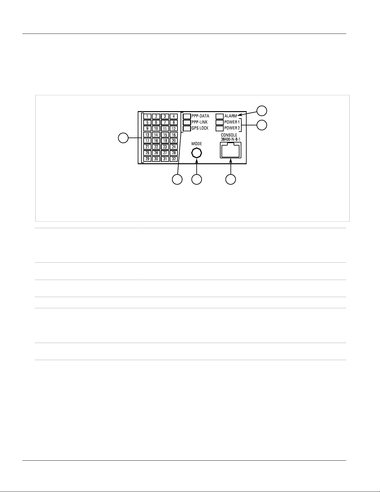
The RX1000 features various ports, controls and indicator LEDs on the front panel for configuring and
troubleshooting the device.
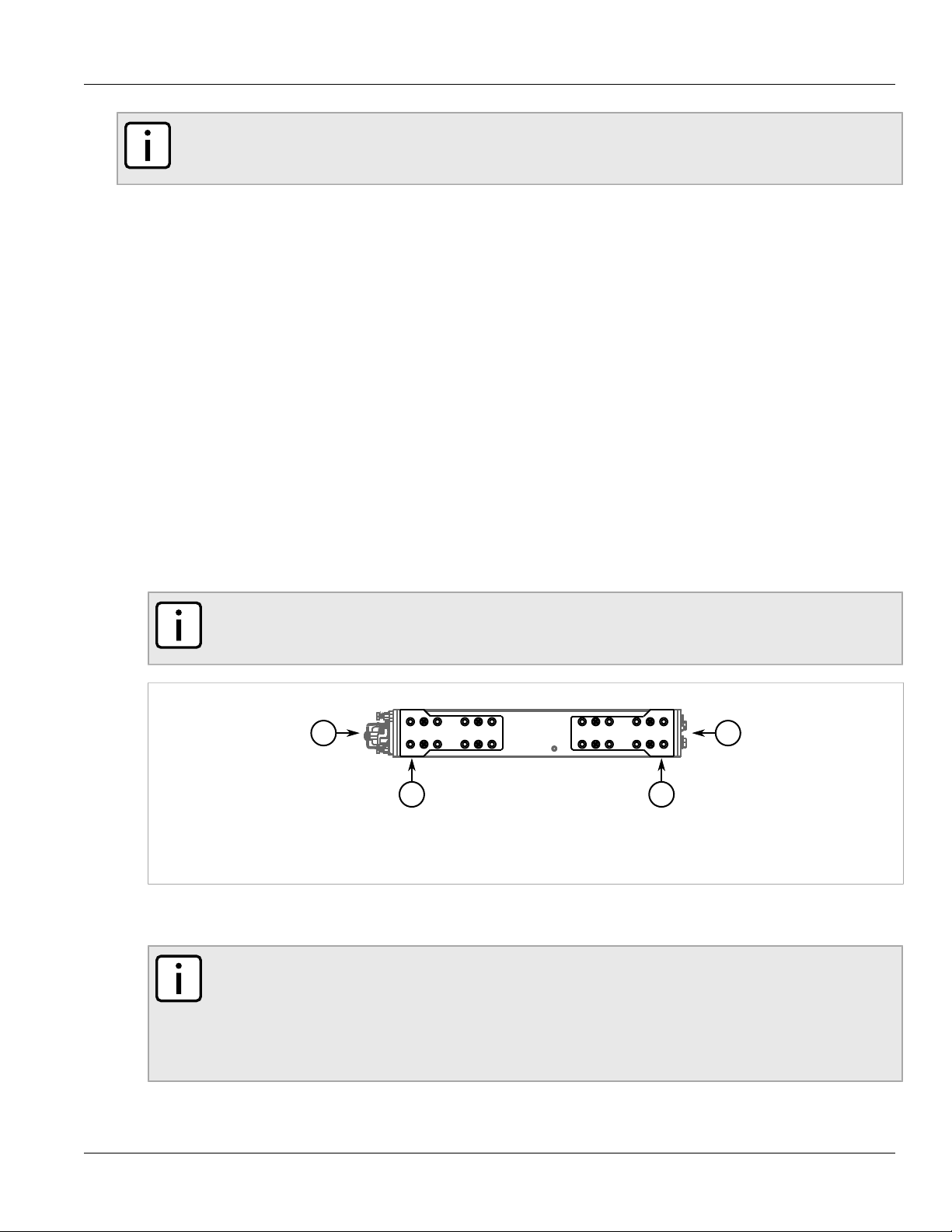
Figure 1: Front Panel
1. Port Status Indicator LEDs 2. Display Mode Indicator LEDs 3. Mode Button 4. Alarm Indicator LED 5. Power Module Indicator
LEDs 6. RS232 Serial Console Port (RJ45)
Chapter 1
Introduction
Port Status Indicator LEDs These LEDs indicate the state of each port.
• Green (Solid) = Link detected
• Green (Blinking) = Link activity
• Off = No link detected
Display Mode Indicator LEDs These LEDs indicate the current display mode for the port status indicator LEDs (i.e. PPP-
Mode button The Mode button sets the display mode for the port status indicator LEDs (i.e. PPP-DATA,
Alarm Indicator LED The alarm indicator LED illuminates when an alarm condition exists.
Power Module Indicator LEDs These LEDs indicate the status of the power modules.
RS232 Serial Console Port This port is for interfacing directly with the device and accessing initial management
DATA, PPP-LINK or GPS LOCK).
PPP-LINK or GPS LOCK). It can also be used to reset the device if held for 5 seconds.
• Green = The power supply is supplying power
• Red = Power supply failure
• Off = No power supply is installed
functions.
Ports, Controls and Indicator LEDs 3
Page 10

RUGGEDCOM RX1000
Installation Guide
Chapter 1
Introduction
Ports, Controls and Indicator LEDs 4
Page 11
RUGGEDCOM RX1000
Installation Guide
Installing the Device
Installing the Device
The following sections describe how to install the device, including mounting the device, installing/removing
modules, connecting power, and connecting the device to the network.
WARNING!
Radiation hazard – risk of serious personal injury. This product contains a laser system and is
classified as a CLASS 1 LASER PRODUCT. Use of controls or adjustments or performance of
procedures other than those specified herein may result in hazardous radiation exposure.
DANGER!
Electrocution hazard – risk of serious personal injury and/or damage to equipment. Before performing
any maintenance tasks, make sure all power to the device has been disconnected and wait
approximately two minutes for any remaining energy to dissipate.
IMPORTANT!
This product contains no user-serviceable parts. Attempted service by unauthorized personnel shall
render all warranties null and void.
Changes or modifications not expressly approved by Siemens Canada Ltd. could invalidate
specifications, test results, and agency approvals, and void the user's authority to operate the
equipment.
Chapter 2
IMPORTANT!
This product should be installed in a restricted access location where access can only be gained by
authorized personnel who have been informed of the restrictions and any precautions that must be
taken. Access must only be possible through the use of a tool, lock and key, or other means of security,
and controlled by the authority responsible for the location.
• Section 2.1, “Mounting the Device”
• Section 2.2, “Connecting Power”
• Section 2.3, “Connecting the Failsafe Alarm Relay”
• Section 2.4, “Grounding the Device”
• Section 2.5, “Cabling Recommendations”
• Section 2.6, “Connecting to the Device”
Section 2.1
Mounting the Device
The RX1000 is designed for maximum mounting and display flexibility. It can be equipped with connectors that
allow it to be installed in a 48 cm (19 in) rack, 35 mm (1.4 in) DIN rail, or directly on a panel.
Mounting the Device 5
Page 12
Chapter 2
3 3
1 2
Installing the Device
RUGGEDCOM RX1000
Installation Guide
NOTE
For detailed dimensions of the device with either rack, DIN rail or panel hardware installed, refer to
Chapter 5, Dimension Drawings.
The following sections describe the various methods of mounting the device:
• Section 2.1.1, “Mounting the Device to a Rack”
• Section 2.1.2, “Mounting the Device on a DIN Rail”
• Section 2.1.3, “Mounting the Device to a Panel”
Section 2.1.1
Mounting the Device to a Rack
For rack mount installations, the RX1000 can be equipped with rack mount adapters pre-installed at the front or
rear of the chassis. Additional adapters are provided to further secure the device in high-vibration or seismically
active locations.
To secure the device to a standard 48 cm (19 in) rack, do the following:
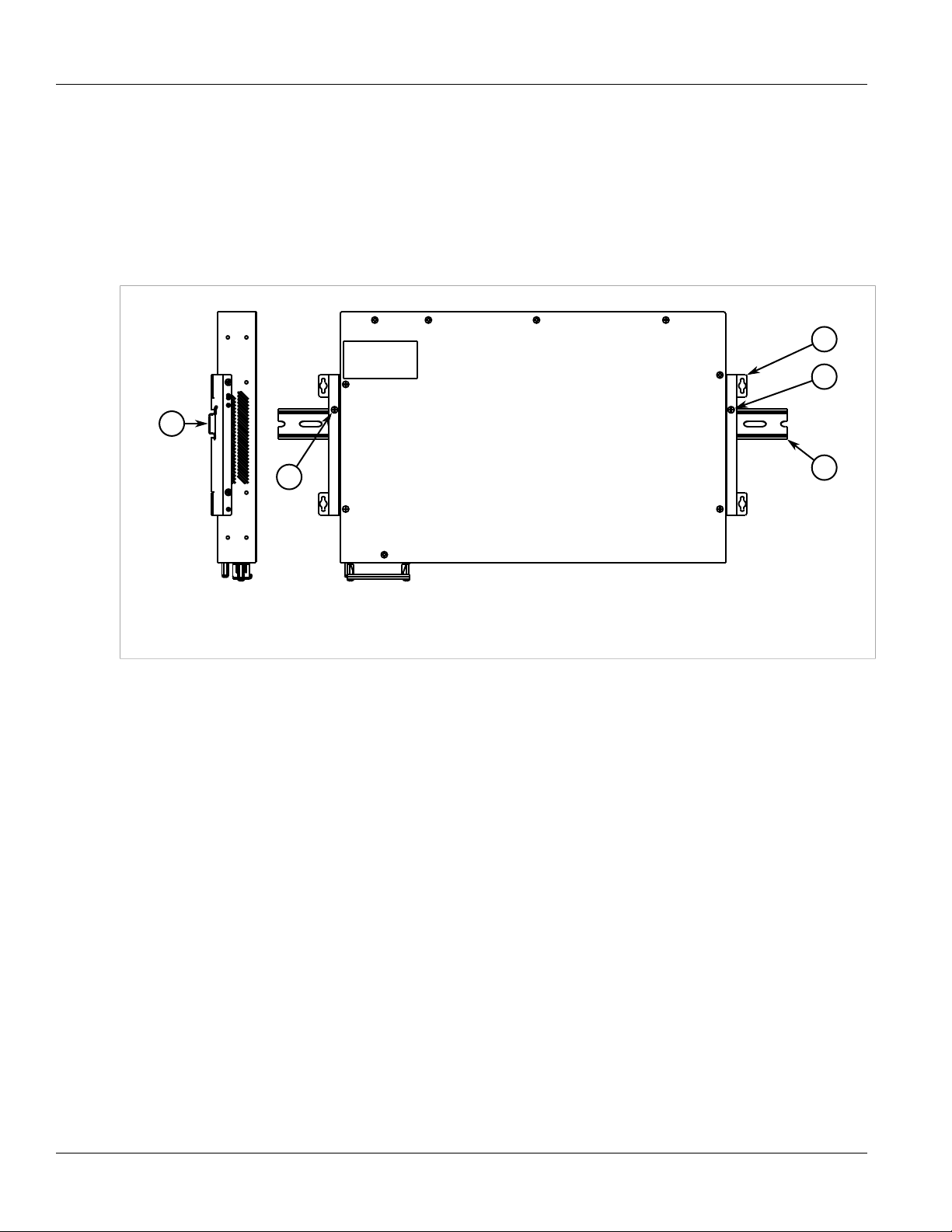
1. Make sure the rack mount adapters are installed on the correct side of the chassis.
• To make the modules and ports accessible, install the rack mount adapters at the rear of the chassis
• To make the management ports and LEDs accessible, install the rack mount adapters at the front of the
chassis
NOTE
The chassis features multiple mounting holes, allowing the rack mount adapters to be installed up
to 25 mm (1 in) from the face of the device.
Figure 2: Rack Mount Adaptors
1. Rear 2. Front 3. Rack Mount Adaptor
2. If required, install adapters on the opposite side of the device to protect from vibrations.
3. Insert the device into the rack.
NOTE
Since heat within the device is channelled to the enclosure, it is recommended that 1 rack-unit
of space, or 44 mm (1.75 in), be kept empty above the device. This allows a small amount of
convectional airflow.
Forced airflow is not required. However, any increase in airflow will result in a reduction of ambient
temperature and improve the long-term reliability of all equipment mounted in the rack space.
4. Secure the adapters to the rack using the supplied hardware.
6 Mounting the Device to a Rack
Page 13
RUGGEDCOM RX1000
2
1
2
3
3
Installation Guide
Section 2.1.2
Installing the Device
Mounting the Device on a DIN Rail
For DIN rail installations, the RX1000 can be equipped with panel/DIN rail adapters pre-installed on each side of
the chassis. The adapters allow the device to be slid onto a standard 35 mm (1.4 in) DIN rail.
To mount the device to a DIN rail, do the following:
1. Align the adapters with the DIN rails and slide the device into place.
Chapter 2
Figure 3: DIN Rail Mounting
1. Panel/DIN Rail Adaptor 2. DIN Rail 3. Screw
2. Install one of the supplied screws on either side of the device to secure the adapters to the DIN rails.
Section 2.1.3
Mounting the Device to a Panel
For panel installations, the RX1000 can be equipped with panel/DIN rail adapters pre-installed on each side of
the chassis. The adapters allow the device to be attached to a panel using screws.
To mount the device to a panel, do the following:
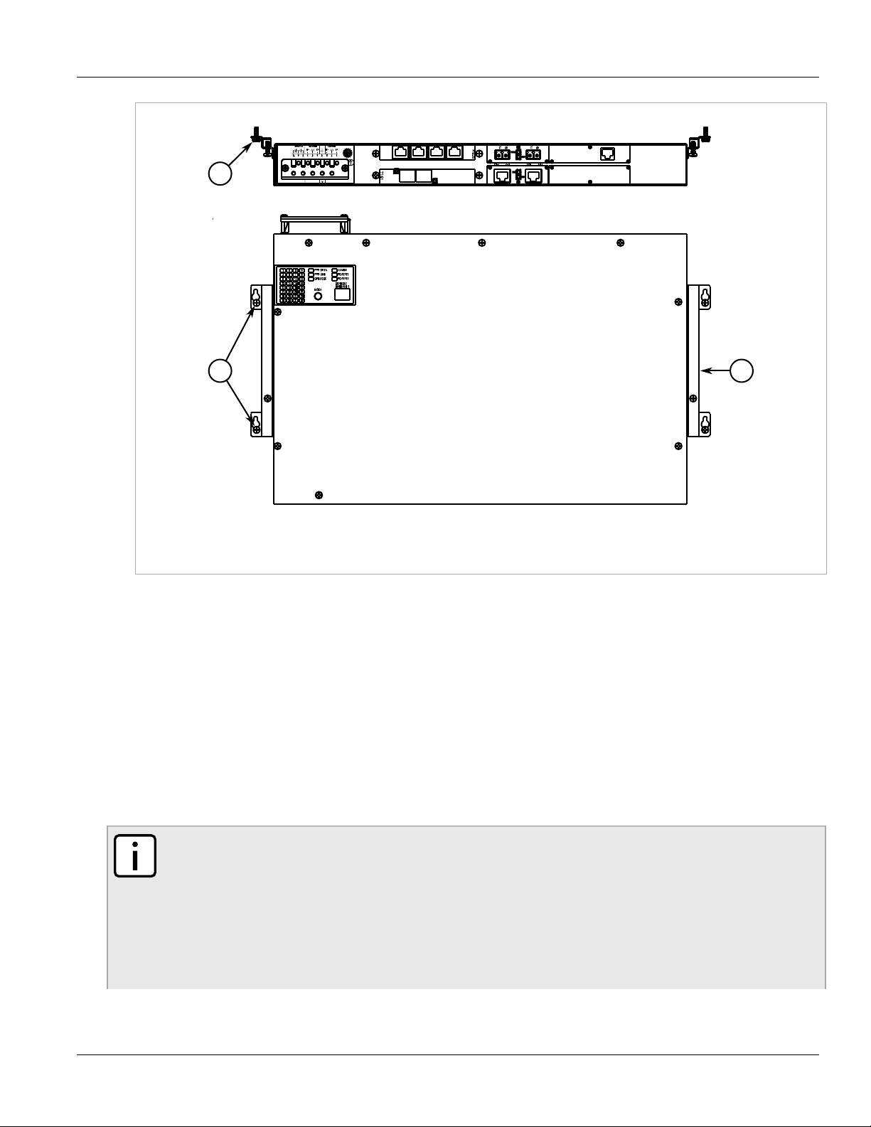
1. Place the device against the panel and align the adapters with the mounting holes.
Mounting the Device on a DIN Rail 7
Page 14
Chapter 2
21
1
Installing the Device
RUGGEDCOM RX1000
Installation Guide
Figure 4: Panel Mounting
1. Screw 2. Panel/DIN Rail Adaptor
2. Install the supplied screws to secure the adapters to the panel.
Section 2.2
Connecting Power
The RX1000 supports single or dual redundant AC and/or DC power supplies. The use of two power modules is
recommended to provide redundancy and load balancing.
The RX1000 can be equipped with either a screw-type or pluggable terminal block, which provides power to both
power supplies. The screw-type terminal block is installed using Phillips screws and compression plates, allowing
either bare wire connections or crimped terminal lugs. Use #6 size ring lugs for secure, reliable connections
under severe shock or vibration.
NOTE
• For maximum redundancy in a dual power supply configuration, use two independent power
sources.
• For 100-240 VAC rated equipment, an appropriately rated AC circuit breaker must be installed.
• For 88-300 VDC rated equipment, an appropriately rated DC circuit breaker must be installed.
• Use only #16 gage copper wiring when connecting terminal blocks.
• A circuit breaker is not required for 12, 24 or 48 VDC rated power supplies.
8 Connecting Power
Page 15
RUGGEDCOM RX1000
Installation Guide
• It is recommended to provide a separate circuit breaker for each power supply module.
• Equipment must be installed according to applicable local wiring codes and standards.
The following sections describe how to connect power to the device:
• Section 2.2.1, “Connecting AC Power”
• Section 2.2.2, “Connecting DC Power”
• Section 2.2.3, “Wiring Examples”
Section 2.2.1
Connecting AC Power
To connect a high AC power supply to the device, do the following:
CAUTION!
Electrical hazard – risk of damage to equipment. Do not connect AC power cables to terminals for DC
power. Damage to the power supply may occur.
Installing the Device
Chapter 2
CAUTION!
Electrical hazard – risk of damage to equipment. Before testing the dielectric strength (HIPOT) in the
field, remove the metal jumper. This metal jumper connects transient suppression circuitry to chassis
ground and must be removed in order to avoid damage to transient suppression circuitry during testing.
NOTE
The terminal block is divided into separate terminals for each internal power supply. Make sure to
connect the external power supply to the appropriate terminals.
1. Remove the terminal block cover.
2. If a screw-type terminal block is installed, remove the screws from the appropriate terminals. Use these
screws along with #6 ring lugs to secure the wires to the terminal block.
3. Connect the positive wire from the power source to the positive/live (+/L) terminal on the terminal block. For
more information, refer to Section 2.2.3, “Wiring Examples”.
Connecting AC Power 9
Page 16

Chapter 2
4
21
34657464
3
65746
5
Installing the Device
Figure 5: Terminal Block Wiring
1. Screw-Type Terminal Block 2. Pluggable Terminal Block 3. Jumper 4. Positive/Live (+/L) Terminal 5. Negative/Neutral (-/N)
Terminal 6. Surge Ground Terminal 7. Chassis Ground Terminal
RUGGEDCOM RX1000
Installation Guide
4. Connect the negative wire from the power source to the negative/neutral (-/N) terminal on the terminal block.
For more information, refer to Section 2.2.3, “Wiring Examples”.
5. Install the supplied metal jumper between terminals 2, 4 and 6 to connect the surge ground terminals to the
chassis ground terminal. The surge ground terminals are used as the ground conductor for all surge and
transient suppression circuitry internal to the unit.
6. Connect the ground terminal on the power source to the chassis ground terminal on the device. For more
information, refer to Section 2.4, “Grounding the Device”
DANGER!
Electrocution hazard – risk of death, serious personal injury and/or damage to the device. Make
sure the supplied terminal block cover is always installed before the device is powered.
7. Install the terminal block cover.
Section 2.2.2
Connecting DC Power
To connect a high or low DC power supply to the device, do the following:
CAUTION!
Electrical hazard – risk of damage to equipment. Before testing the dielectric strength (HIPOT) in the
field, remove the metal jumper. This metal jumper connects transient suppression circuitry to chassis
ground and must be removed in order to avoid damage to transient suppression circuitry during testing.
NOTE
The terminal block is divided into separate terminals for each internal power supply. Make sure to
connect the external power supply to the appropriate terminals.
10 Connecting DC Power
Page 17

RUGGEDCOM RX1000
4
21
34657464
3
65746
5
Installation Guide
Installing the Device
NOTE
The screw-type terminal block is installed using Philips screws and compression plates, allowing either
bare wire connections or crimped terminal lugs. Use #6 size ring lugs for secure, reliable screws, which
must be removed to make connections.
1. Remove the terminal block cover.
2. If a screw-type terminal block is installed, remove the screws from the appropriate terminals. Use these
screws along with #6 ring lugs to secure the wires to the terminal block.
3. Connect the positive wire from the power source to the positive/live (+/L) on the terminal block. For more
information, refer to Section 2.2.3, “Wiring Examples”.
Chapter 2
Figure 6: Terminal Block Wiring
1. Screw-Type Terminal Block 2. Pluggable Terminal Block 3. Jumper 4. Positive/Live (+/L) Terminal 5. Negative/Neutral (-/N)
Terminal 6. Surge Ground Terminal 7. Chassis Ground Terminal
4. Connect the negative wire from the power source to the negative/neutral (-/N) on the terminal block. For
more information, refer to Section 2.2.3, “Wiring Examples”.
5. Install the supplied metal jumper between terminals 2, 4 and 6 to connect the surge ground terminals to the
chassis ground terminal. The surge ground terminals are used as the ground conductor for all surge and
transient suppression circuitry internal to the unit.
6. Connect the ground terminal on the power source to the chassis ground terminal on the device. For more
information, refer to Section 2.4, “Grounding the Device”
DANGER!
Electrocution hazard – risk of death, serious personal injury and/or damage to the device. Make
sure the supplied terminal block cover is always installed before the device is powered.
7. Install the terminal block cover.
Connecting DC Power 11
Page 18

Chapter 2
Installing the Device
Section 2.2.3
Wiring Examples
The following illustrate how to connect power to single and dual power supplies.
RUGGEDCOM RX1000
Installation Guide
Figure 7: Single AC Power Supply
Figure 8: Single DC Power Supply
12 Wiring Examples
Page 19

RUGGEDCOM RX1000
Installation Guide
Figure 9: Dual AC Power Supply
Installing the Device
Chapter 2
Figure 10: Dual DC Power Supply
Wiring Examples 13
Page 20

Chapter 2
Installing the Device
Figure 11: Dual AC/DC Power Supply
RUGGEDCOM RX1000
Installation Guide
Section 2.3
Connecting the Failsafe Alarm Relay
The failsafe relay can be configured to latch based on alarm conditions. The NO (Normally Open) contact is
closed when the unit is powered and there are no active alarms. If the device is not powered or if an active alarm
is configured, the relay opens the NO contact and closes the NC (Normally Closed) contact.
NOTE
Control of the failsafe relay output is configurable through ROX . One common application for this relay
is to signal an alarm if a power failure occurs. For more information, refer to the ROX User Guide for
the RX1000.
The following shows the proper relay connections.
14 Connecting the Failsafe Alarm Relay
Page 21

RUGGEDCOM RX1000
1
3
2
2
1
3
Installation Guide
Figure 12: Failsafe Alarm Relay Wiring
1. Normally Open 2. Common 3. Normally Closed
Section 2.4
Installing the Device
Chapter 2
Grounding the Device
The RX1000 chassis ground terminal uses a #6-32 screw. It is recommended to terminate the ground connection
with a #6 ring lug and torque it to 1.7 N·m (15 lbf·in).
Figure 13: Chassis Ground Connection
1. Stainless Steel Stud 2. #6-32 Screw 3. #6 Ring Lug
Section 2.5
Cabling Recommendations
Siemens does not recommend the use of copper cabling of any length for critical, real-time substation automation
applications. All copper Ethernet ports on RUGGEDCOM products include transient suppression circuitry
to protect against damage from electrical transients and conform with IEC 61850-3 and IEEE 1613 Class 1
standards. This means that during a transient electrical event, communications errors or interruptions may occur,
but recovery is automatic.
Grounding the Device 15
Page 22

Chapter 2
18
Installing the Device
RUGGEDCOM RX1000
Installation Guide
Siemens also does not recommend using copper Ethernet ports to interface with devices in the field across
distances that could produce high levels of ground potential rise (i.e. greater than 2500 V), during line-to-ground
fault conditions.
Section 2.6
Connecting to the Device
The following describes the various methods for accessing the ROX console and Web interfaces on the device.
For more detailed instructions, refer to the ROX User Guide for the RX1000.
RS232 Console Port
Connect a PC or terminal directly to the RS232 console port to access the boot-time control and ROX interfaces.
The console port provides access to ROX's console and Web interfaces.
IMPORTANT!
The console port is intended to be used only as a temporary connection during initial configuration or
troubleshooting.
Connection to the console port is made using an RJ45-to-DB9 console cable. The following is the pin-out for the
console port:
Pin
Name Description
a
a
b
b
c
Data Set Ready
Data Terminal Ready
(from DTE)
Clear to Send
Read to Send
Ring Indicator
Figure 14: RJ45 Console Port Pin Configuration
a
The DSR, DCD and DTR pins are connected together internally.
b
The CTS and RTS pins are connected together internally.
c
RI is not connected.
RJ45 Male
1 6 DSR
2 1 Reserved (Do Not Connect)
3 4 DTR
4 5 GND Signal Ground
5 2 RxD Receive Data (to DTE)
6 3 TxD Transmit Data
7 8 CTS
8 7 RTS
1 9 RI
DB9
Female
Communication Ports
Connect any of the available Ethernet ports on the device to a management switch and access the ROX console
and Web interfaces via the device's IP address. For more information about available ports, refer to Chapter 3,
Communication Ports.
16 Connecting to the Device
Page 23

RUGGEDCOM RX1000
3
4
1
2
5
6
Installation Guide
Communication Ports
Communication Ports
The RX1000 can be equipped with various types of communication ports to enhance its abilities and
performance. To determine which ports are equipped on the device, refer to the factory data file available through
ROX . For more information on how to access the factory data file, refer to the ROX User Guide for the RX1000.
Each communication port type has a specific place in the RX1000 chassis.
Chapter 3
Figure 15: Port Assignment
1. Slot 1 2. Slot 2 3. Slot 3 4. Slot 4 5. Slot 5 6. Slot 6
Slot(s) Communication Port
1 GSM/EDGE cellular modem
1, 2 V.90 modem
RS232 external modem
3, 4 Copper 10/100Base-Tx Ethernet with RJ45 ports
Fiber 100Base-FX multi-mode or single-mode Ethernet with ST, SC, LC or MTRJ ports
5, 6 Single T1/E1 Channelized/Unchannelized
Dual T1/E1 Channelized/Unchannelized
Quad T1/E1 Channelized/Unchannelized
Clear Channel T3 DS3 card
DSL card
56 kBbps DDS DSU/CSU card
Precision Time Protocol (PTP) card
Serial RS232/RS422/RS485 card with RJ45 ports
Synchronous dual serial card with DB25 ports
GSM/EDGE/HSPA cellular modem
EVDO Rev.A Verizon (US) wireless cellular modem
The following sections describe the available ports in more detail:
• Section 3.1, “Copper Ethernet Ports”
• Section 3.2, “WAN Ports”
• Section 3.3, “DSL Ports”
17
Page 24

Chapter 3
18
Communication Ports
• Section 3.4, “DDS Ports”
• Section 3.5, “Modem Port”
• Section 3.6, “Serial Ports”
• Section 3.7, “Precision Time Protocol (PTP) Ports”
• Section 3.8, “RS232 External Modem Ports”
• Section 3.9, “Cellular Modems”
• Section 3.10, “Connecting Multiple RS485 Devices”
Section 3.1
Copper Ethernet Ports
The RX1000 supports several 10/100Base-TX Ethernet ports that allow connection to standard Category 5
(CAT-5) unshielded twisted-pair (UTP) cables with RJ45 male connectors. The RJ45 connectors are directly
connected to the chassis ground on the device and can accept CAT-5 shielded twisted-pair (STP) cables.
Each port features a Speed and Link LED that indicates the state of the port.
RUGGEDCOM RX1000
Installation Guide
LED State Description
Yellow The port is operating at 100 MbpsSpeed
Off The port is operating at 10 Mbps
Link
Yellow (Solid) Link established
Yellow (Blinking) Link activity
Off No link detected
The following is the pin-out for the RJ45 male connector:
Pin Name Description
1 RX+ Receive Data+
2 RX- Receive Data-
3 TX+ Transmit Data+
Figure 16: RJ45 Ethernet Port Pin Configuration
4 Reserved (Do Not Connect)
5 Reserved (Do Not Connect)
6 TX- Transmit Data-
7 Reserved (Do Not Connect)
8 Reserved (Do Not Connect)
For specifications on the available copper Ethernet ports, refer to Section 4.3, “Copper Ethernet Port
Specifications”.
18 Copper Ethernet Ports
Page 25

RUGGEDCOM RX1000
18
16
Installation Guide
Section 3.2
Communication Ports
WAN Ports
The RX1000 can optionally be equipped with T1/E1 WAN ports, which communicate on standard telephony
communication lines.
T1/E1 WAN ports are equipped with standard RJ45 receptacles. The following is the pin-out for the T1/E1 ports:
Pin Description
1 RRING
2 RTIP
3 Reserved (Do Not Connect)
Chapter 3
Figure 17: RJ45 T1/E1 Port Pin Configuration
Section 3.3
4 TRING
5 TTIP
6 Reserved (Do Not Connect)
7 Reserved (Do Not Connect)
8 Reserved (Do Not Connect)
DSL Ports
The RX1000 can optionally be equipped with a dual-port DSL (Digital Subscriber Line) card, which can
communicate over standard telephone communication lines. The DSL card supports the following modulation
standards:
• G.992.1 (G.DMT)
• G.992.2 (G.Lite)
• G.992 Annex A (ADSL over POTS)
Each DSL card is equipped with standard RJ11 telephone ports. The following is the pin-out description for the
RJ11 ports:
Pin Description
1 Reserved (Do Not Connect)
2 Reserved (Do Not Connect)
3 Ring
Figure 18: RJ11 Port Port Pin Configuration
WAN Ports 19
4 Tip
5 Reserved (Do Not Connect)
6 Reserved (Do Not Connect)
Page 26

Chapter 3
18
16
Communication Ports
Section 3.4
DDS Ports
The RX1000 can optionally be equipped with a 56/64 kbps DDS (Data Distribution Service) card that uses
standard RJ45 receptacles.
The following is the pin-out for the DDS ports:
Pin Name Description
RUGGEDCOM RX1000
Installation Guide
Figure 19: DDS RJ45 Port Pin Configuration
Section 3.5
1 R1 Transmit data to
2 T1 Transmit data to
3 Reserved (Do Not Connect)
4 Reserved (Do Not Connect)
5 Reserved (Do Not Connect)
6 Reserved (Do Not Connect)
7 T Receive data
8 R Receive data from
network (Ring 1)
network (Tip 1)
from network (Tip)
network (Ring)
Modem Port
The RX1000 can optionally be equipped with a V.90 Modem connection for PPP (Point-to-Point Protocol)
connections. For information about how to configure and operate the modem, refer to the ROX User Guide for the
RX1000.
WARNING!
Fire hazard – risk of serious personal injury and/or damage to equipment. To reduce the risk of fire, use
only #26 AWG or larger telecommunication line cord.
The modem card is equipped with a standard RJ11 telephone port. The following is the pin-out description for the
RJ11 port:
Pin Description
1 Reserved (Do Not Connect)
2 Reserved (Do Not Connect)
3 Ring
Figure 20: RJ11 Port Pin Configuration
20 DDS Ports
4 Tip
5 Reserved (Do Not Connect)
6 Reserved (Do Not Connect)
Page 27

RUGGEDCOM RX1000
1
25
13
14
Installation Guide
Communication Ports
NOTE
This product meets the applicable Industry Canada technical specifications.
The Ringer Equivalence Number is an indication of the maximum number of devices allowed to be
connected to a telephone interface. The termination on an interface may consist of any combination of
devices subject only to the requirement that the sum of the RENs of all the devices does not exceed
five.
Section 3.6
Serial Ports
The RX1000 supports serial cards with DB25 or RJ45 serial ports. Serial RJ45 ports can be run in RS232, RS485
or RS422 mode.
NOTE
On power-up, all serial RJ45 ports default to RS485 mode. Each port can be individually set to RS232,
RS485 or RS422 mode through ROX . For more information, refer to the ROX User Guide for the
RX1000.
Chapter 3
NOTE
For information about how to connect devices configured to run in RS485 mode, refer to Section 3.10,
“Connecting Multiple RS485 Devices”.
All serial ports feature an LED that indicates the current state of the port.
State Description
Green Link activity detected
Off No link detected
For specifications on serial ports, refer to Section 4.4, “Serial Port Specifications”.
The following is the pin-out description for DB25 and RJ45 serial ports:
Pin Name Description
1
2 TxD Transmit Data
3 RxD Receive Data
4 RTS Request To Send
5 CTS Clear To Send
6
Figure 21: Serial DB25 Port Pin Configuration
7 GND Common Ground
8 DCD Carrier Detect
9
Serial Ports 21
10
11
Page 28

Chapter 3
18
Communication Ports
RUGGEDCOM RX1000
Installation Guide
Pin Name Description
12
13
14
15 TxCLK Transmit Clock
16 RxCLK Receive Clock
17
18
19
20 DTR Data Terminal Ready
21
22
23
24
25
Pin RS232 Mode RS485 Mode RS422 Mode
a
1
a
2
3 DTR
Figure 22: Serial RJ45 Port Pin Configuration
a
Connected internally.
b
In RS232 mode, this pin enters a high impedance state. A DTE that asserts RTS will see CTS asserted, although the device will not perform hardware flow
control.
4 Common (Isolated) Ground
5 RX RX+
6 TX TX/RX+ TX+
7 CTS
8 RTS
Shield Chassis Ground
DSR/RI RX-
DCD
ab
b
TX/RX- TX-
Section 3.7
Precision Time Protocol (PTP) Ports
The optional Precision Time Protocol (PTP) card for the RX1000 provides accurate time synchronization across
local and wide area networks. The PTP card is capable of using a variety of time synchronization methods
including Network Time Protocol (NTP), IRIG-B, and IEEE 1588, making it a flexible product for new and existing
installations.
22 Precision Time Protocol (PTP) Ports
Page 29

RUGGEDCOM RX1000
1 2 3 4 5
Installation Guide
Figure 23: PTP Card
1. IEEE 1588 Ethernet Interface 2. GPS Antenna Input 3. IRIG-B AM Output 4. IRIG-B PWM (TTL) or PPS Output 1 5. IRIG-B PWM
(TTL) or PPS Output 2
Communication Ports
NTP is the standard for synchronizing the clocks of computer systems throughout the Internet and is suitable for
systems that require accuracies in the order of 1 ms. IRIG-B time synchronization relies on the Global Positioning
System (GPS) as the source of accurate time and requires an external GPS antenna input to provide accurate
time signals on the order of 100 µs. IEEE 1588 is designed to fill a niche not well served by either of the two
dominant protocols, NTP and IRIG-B. IEEE 1588 is designed for local systems requiring accuracies on the order
of 100 nanoseconds. IEEE 1588 is also designed for applications that cannot bear the cost of a GPS receiver at
each node or for which GPS signals are inaccessible.
The PTP card is an ideal product for use in existing installations already well served by NTP and/or GPS. It also
provides a migration path for the use of the new IEEE 1588 standard. As more end devices enter the market with
IEEE 1588 compatibility, this card provides an easy transition to this new time synchronization standard.
The following sections describe the PTP card in more detail:
• Section 3.7.1, “IRIG-B Outputs”
• Section 3.7.2, “Pulse-Per-Second (PPS) Output”
• Section 3.7.3, “GPS Antenna Installation Recommendations”
Chapter 3
Section 3.7.1
IRIG-B Outputs
The PTP Card supports both IRIG-B outputs in both Amplitude Modulated (AM) and Pulse Width Modulation
(PWM) formats. Specifically, for the AM output, IRIG-B122 and IRIG-B123 are supported. For the PWM output,
IRIG-B002 and IRIG-B003 are supported. Enabling of the AM and PWM outputs is done through software.
The number of IRIG-B devices that can be connected to the AM or PWM source is dependent on the cabling type
and length as well as the input impedances of the devices. Figure 16 shows a simplified circuit diagram of the
interface between the IRIG-B source and connected devices.
IRIG-B Outputs 23
Page 30

Chapter 3
1
2
3
Communication Ports
Figure 24: IRIG-B Simplified Schematic
1. Source 2. Cabling 3. Device
RUGGEDCOM RX1000
Installation Guide
The maximum number of devices (N) that can be connected to the source is determined by checking if the source
current (IS) required to drive the connected devices is less than the maximum drive current the source can
provide, and verifying that the load voltage (VL) the connected devices see is greater than the minimum required
voltage.
For specifications for the IRIG-B outputs, refer to Section 4.5, “IRIG-B Output Specifications”.
Section 3.7.2
Pulse-Per-Second (PPS) Output
The PTP card supports one Pulse-Per-Second (PPS) output. When enabled through ROX, the card outputs a 5 V
pulse every second.
Section 3.7.3
GPS Antenna Installation Recommendations
The signals received from the GPS satellite network are at a frequency of 1575.42 MHz with a minimum power
of -162 dBW. The GPS antenna must have a clear view of the sky in order to receive the low power signals and
track the maximum number of satellites. Rooftops or other structures clear of obstructions and with a clear view
of the horizon are ideal.
Elements of a typical GPS antenna system include:
• Active GPS Antenna (required)
• Coaxial cable to connect the elements (required)
• Lightning arrestor (optional)
• Line Amplifier or Filter (optional)
To establish proper GPS signal reception, the overall system of antenna, cabling, lightning arrestor, line amplifier
and filters requires a relative gain which should be greater than 5 dBi but less than 18 dBi (to avoid signal
saturation at the receiver input).
24 Pulse-Per-Second (PPS) Output
Page 31

RUGGEDCOM RX1000
Installation Guide
Communication Ports
The following sections describe each component in the GPS antenna system in more detail:
• Section 3.7.3.1, “GPS Antenna”
• Section 3.7.3.2, “Antenna Cabling”
• Section 3.7.3.3, “Lightning Considerations”
• Section 3.7.3.4, “Line Amplification and Filtering”
Section 3.7.3.1
GPS Antenna
There are two major types of GPS antenna: passive and active. A passive antenna requires no power and is
an option when signal strength is not a concern. An active antenna has a built in Low Noise Amplifier (LNA)
to increase the strength of the signal, and to compensate for the signal loss in a long cable connection. Active
antennas are used when the antenna input is connected to the receiver through a coaxial cable (usually longer
than 3 m) or any high loss transmission path.
NOTE
• The PTP card’s GPS input provides 5 VDC at up to 10 mA to power the antenna.
• Best results can be achieved with a total gain of 16 dB (includes antenna gain, cable loss, lightning
arrestor loss, line amplifier gain and filter loss) at the antenna input.
Chapter 3
The PTP Card requires an active antenna with the following specifications:
Characteristic Active Antenna
Polarization Right-Hand Circular Polarized
Receive Frequency 1.57542 GHz ± 1.023 MHz
Power Supply 5 VDC
DC Current < 10 mA at 3 VDC
Antenna Gain Select antenna gain based on system configuration
Total Gain at PTP GPS Input (includes antenna gain, cable
loss, lightning arrestor loss, line amplifier gain and filter loss)
Axial Ratio < 3 dB
Output VSWR < 2.5
Section 3.7.3.2
Total Gain ≤ 18 dBi
Antenna Cabling
Cable Impedance: Siemens recommends low loss 50 Ω coaxial cabling.
Cable Delay: Using any length of coaxial cable will add some time delay to the GPS signal which degrades
the accuracy of the calculated time and position. The time delay is dependent on the type of dielectric material
in the cable and ranges from 1 to 2 ns/ft. Siemens provides a method to account for this delay through the
web management interface by entering the time delay into the cable compensation box under PTP General
Configuration. The table below gives some examples of the delay that can be expected based on the dielectric
type.
GPS Antenna 25
Page 32

Chapter 3
Communication Ports
Dielectric Type Time Delay(ns/ft) PropagationVelocity(% of c)
Solid Polyethylene (PE) 1.54 65.9
Foam Polyethylene (FE) 1.27 80.0
Foam Polystyrene (FS) 1.12 91.0
Air Space Polyethylene (ASP) 1.15-1.21 84-88
Solid Teflon (ST) 1.46 69.4
Air Space Teflon (AST) 1.13-1.20 85-90
Section 3.7.3.3
RUGGEDCOM RX1000
Installation Guide
Lightning Considerations
Although it is not possible to protect the antenna from a direct lighting strike, the antenna and connected
components can be protected from secondary affects through installation location and protection devices.
Install the antenna at least 15 meters away from and lower than any structures that attract lightning. GPS
antenna damage is usually not the result of a direct lightning strike, but due to high currents induced by the
effects of a lightning strike on a nearby structure. Siemens also recommends installing lightning arrestors in the
antenna line to protect the receiver and connected devices. If a lightning arrestor is installed it is important to
ensure that it has a low impedance path to ground.
Section 3.7.3.4
Line Amplification and Filtering
Although an active antenna has gain, depending on the length of the coaxial cable used it may not be enough in
which case a line amplifier will be required as well.
Most active antennas include filters. However, if there is a high potential for electromagnetic interference, such
as from the near field of a radio transmitter, though the antenna system, additional antenna line filtering may be
necessary.
Section 3.8
RS232 External Modem Ports
The optional RS232 external modem card provides all of the handshaking signals required to control an external
modem via a female DB9 connector.
The following is the pin-out for DB9 ports operating in RS232 mode:
26 Lightning Considerations
Page 33

RUGGEDCOM RX1000
5
9 6
1
Installation Guide
Communication Ports
Chapter 3
Pin Name Description
1 CD Carrier Detect
2 RxD Receive data
3 TxD Transmit Data
4 DTR Data Terminal Ready
5 GND Common Ground
6 DSR Data Set Ready
Figure 25: Serial DB9 Port Pin Configuration
7 RTS Request To Send
8 CTS Clear To Send
9 RI (No
Connection)
Ring Indicator
NOTE
Although a DB9 RS232 DTE (Data Terminal Equipment) connector is ordinarily male, the female
connector has been used here for reasons of durability (i.e. there are no pins to bend). Use a
commonly available male-to-male DB9 adapter (not a NULL-modem) to adapt this connection to a
standard straight-through RS232 cable.
Section 3.9
Cellular Modems
The RX1000 supports the following cellular modem line modules for operation on GSM, EDGE, HSPA+, or CDMA
networks:
NOTE
The cellular modems feature 50 Ω SMA antenna connectors on the front plate of each module.
The HSPA option is available for use on various GSM-based networks. This option supports GSM,
GPRS, EDGE, UMTS and WCDMA/HSDPA/HSUPA. The Main antenna and Receive Diversity antenna
connections are made to the 50 Ω SMA connectors.
The following sections describe the cellular modem modules in more detail:
• Section 3.9.1, “EVDO Cellular Modem”
• Section 3.9.2, “HSPA (GSM) Cellular Modem”
• Section 3.9.3, “GSM/EDGE Internal Cellular Modem”
Section 3.9.1
EVDO Cellular Modem
The EVDO dual band card option is offered for use on Verizon's cellular network. The radio supports IS-95A,
Cellular Modems 27
1xRTT, 1xEVDO Rev0 and 1xEVDO RevA, and will automatically select the fastest mode available when a data
call is made. Main antenna and Receive Diversity antenna connections are made to the 50 Ω SMA connectors
located on the front faceplate.
Page 34

Chapter 3
1
2
1
2
3
Communication Ports
Figure 26: EVDO Cellular Modem
The EVDO cellular modem has the following minimum requirements:
RUGGEDCOM RX1000
Installation Guide
Band
Cell 824-849 869-894 4.95
PCS 1850-1910 1930-1990
Frequency Range (MHz)
VSWR
Tx Rx
<2:1 <2:1
RX Diversity
Support
Maximum
Allowable
Gain (dBi)
Contact Verizon for information about account activation.
Section 3.9.2
HSPA (GSM) Cellular Modem
The HSPA card option is available for use on various GSM-based networks. The card supports GSM, GPRS,
EDGE, UMTS and WCDMA/HSDPA/HSUPA. The Main and Receive Diversity antenna connections are made to
the 50 Ω SMA connectors located on the front faceplate.
3.55
Figure 27: HSPA Cellular Modem
1. Receive Diversity Antenna SMA Connector 2. Access Panel 3. Main Antenna SMA Connector
Installing a SIM Card
SIM card access is available on the front faceplate of the HSPA module. Follow these steps to install a SIM card:
1. Disconnect power from the device.
2. Remove the protective cover marked HSPA.
3. Insert the SIM card with the angled side first. An audible click will indicate the SIM card is in position.
4. Slide the latch over the SIM card to secure it in place.
5. Install the protective cover.
6. Connect power to the device.
28 HSPA (GSM) Cellular Modem
Page 35

RUGGEDCOM RX1000
1
Installation Guide
Supported Frequency Bands
WARNING!
Electromagnet radiation hazard – risk of serious injury. Do not exceed the maximum antenna gain.
Aside from causing cellular interference for other devices that use the same band, adverse health
effects for individuals in the area may occur.
Communication Ports
Chapter 3
Band
Band I
WCDMA 2100
Band II
WCDMA 1900
Band V
WCDMA 850
Band VI
WCDMA 800
GSM 850 824-849 <2.5:1 869-894 <3.5:1 5
EGSM 900 880-915 <2.5:1 925-960 <3.5:1 5
GSM 1800 1710-1785 <2.5:1 1805-1880 <3.5:1 4
GSM 1900 1850-1910 <2.5:1 1930-1990 <2.5:1 4
Tx (MHz) VSWR Rx (MHz) VSWR
1920-1980 <2.5:1 2110-2170 <3.5:1 Y 4
1850-1910 <2.5:1 1930-1990 <2.5:1 Y 4
824-849 <2.5:1 869-894 <3.5:1 Y 5
830-840 <2.5:1 875-885 <3.5:1 Y 5
Frequency Range
Section 3.9.3
GSM/EDGE Internal Cellular Modem
RX Diversity
Support
Maximum
Allowable
Gain (dBi)
The GSM/EDGE internal cellular modem option is available for use on various GSM-based networks. The card
supports GSM and EDGE. The single antenna connection is made to the 50 Ω SMA connector located on the
front faceplate.
Figure 28: GSM/EDGE Internal Cellular Modem
1. SMA Connector
Installing a SIM Card
The SIM card is accessed through the access panel on top of the RX1000. To install a SIM card, follow these
steps:
1. Disconnect power from the device.
2. Remove the access panel.
GSM/EDGE Internal Cellular Modem 29
Page 36

Chapter 3
Communication Ports
3. Insert the SIM card with the angled side first. An audible click will indicate the SIM card is in position.
4. Install the access panel.
5. Connect power to the device.
Supported Frequency Bands
WARNING!
Electromagnet radiation hazard – risk of serious injury. Do not exceed the maximum antenna gain.
Aside from causing cellular interference for other devices that use the same band, adverse health
effects for individuals in the area may occur.
RUGGEDCOM RX1000
Installation Guide
Band
Frequency Range
Tx (MHz) VSWR Rx (MHz) VSWR
GSM 850 824-849 <2.5:1 869-894 <3.5:1 5
EGSM 900 880-915 <2.5:1 925-960 <3.5:1 5
GSM 1800 1710-1785 <2.5:1 1805-1880 <3.5:1 4
GSM 1900 1850-1910 <2.5:1 1930-1990 <2.5:1 4
Section 3.10
Maximum
Allowable
Gain (dBi)
Connecting Multiple RS485 Devices
Each RS485 port can communicate with multiple RS485 devices by wiring devices together in sequence over a
single twisted pair with transmit and receive signals on the same two wires (half duplex). For reliable, continuous
communication, adhere to the following guidelines:
• To minimize the effects of ambient electrical noise, use shielded cabling.
• The correct polarity must be observed throughout a single sequence or ring.
• The number of devices wired should not exceed 32, and total distance should be less than 1219 m (4000 ft) at
100 kbps.
• The Common terminals should be connected to the common wire inside the shield.
• The shield should be connected to earth ground at a single point to avoid loop currents.
• The twisted pair should be terminated at each end of the chain.
The following shows the recommended RS485 wiring.
30 Connecting Multiple RS485 Devices
Page 37

RUGGEDCOM RX1000
< 1219 m (4000 in)
120Ω 10nF
120Ω 10nF
1
2
3
5
5
6
4
Installation Guide
Communication Ports
Chapter 3
Figure 29: Recommended RS485 Wiring
1. RX1000 Device 2. Common (Isolated Ground) 3. Negative 4. Positive 5. Shield to Earth (Connected At a Single Point)
6. RS485 Devices (32 Total)
Connecting Multiple RS485 Devices 31
Page 38

RUGGEDCOM RX1000
Installation Guide
Communication Ports
Chapter 3
Connecting Multiple RS485 Devices 32
Page 39

RUGGEDCOM RX1000
Installation Guide
Technical Specifications
Technical Specifications
The following sections provide important technical specifications related to the device and available modules:
• Section 4.1, “Power Supply Specifications”
• Section 4.2, “Failsafe Relay Specifications”
• Section 4.3, “Copper Ethernet Port Specifications”
• Section 4.4, “Serial Port Specifications”
• Section 4.5, “IRIG-B Output Specifications”
• Section 4.6, “Operating Environment”
• Section 4.7, “Mechanical Specifications”
Section 4.1
Chapter 4
Power Supply Specifications
Power Supply Type
12 VDC
24 VDC
48 VDC 36 VDC 59 VDC 3.15 A(T)
HI (125/250 VDC)
HI (110/230 VAC)
a
(F) denotes fast-acting fuse
b
(T) denotes time-delay fuse.
c
Power consumption varies based on configuration. 10/100Base-TX ports consume roughly 1 W less than fiber optic ports.
d
The HI power supply is the same power supply for both AC and DC.
d
d
Minimum Maximum
10 VDC 36 VDC 6.3 A(F)
88 VDC 300 VDC
85 VAC 264 VAC
Input Range
Section 4.2
Internal Fuse
ab
Rating
2 A(T) 4 kVAC, 5.5 kVDC
Failsafe Relay Specifications
Isolation
1.5 kVDC
Maximum Power
Consumption
25 W
c
Parameter Value (Resistive Load)
Max Switching Voltage 30 VAC, 80 VDC
Rated Switching Current
0.3 A @ 30 VAC
1 A @ 30 VDC, 0.3 A @ 80 VDC
Power Supply Specifications 33
Page 40

Chapter 4
Technical Specifications
Section 4.3
Copper Ethernet Port Specifications
The following details the specifications for copper Ethernet ports that can be ordered with the RX1000.
RUGGEDCOM RX1000
Installation Guide
e
Speed
10/100Base-TX RJ45 FDX/HDX > CAT-5 TIA/EIA T568A/B 100 m (328 ft) 1.5 kV
e
Auto-negotiating.
f
Shielded or unshielded.
g
Auto-crossover and auto-polarity.
h
Typical distance. Dependent on the number of connectors and splices.
i
RMS 1 minute.
Connector Duplex
e
Cable Type
f
Wiring
Standard
g
Maximum
Distance
h
Section 4.4
Serial Port Specifications
Baud Rate Connector Isolation
300 to 230 kbps
Section 4.5
RJ45
2.5 kV
DB25
Isolation
i
IRIG-B Output Specifications
Parameter Typical Value
Output Current (IS) 40 mA total between two output ports
Output Voltage (VS) 5 Vp-p
Output Impedance (RS) 25 Ω
Section 4.6
Operating Environment
Parameter Range Comments
Ambient Operating Temperature -40 to 85 °C
(-40 to 185 °F)
Ambient Relative Humidity 5% to 95% Non-condensing
Ambient Storage Temperature -40 to 85 °C
(-40 to 185 °F)
Measured from a 30 cm (12 in) radius surrounding the center of the
enclosure.
34 Copper Ethernet Port Specifications
Page 41

RUGGEDCOM RX1000
Installation Guide
Section 4.7
Mechanical Specifications
Parameter Value
Dimensions Refer to Chapter 5, Dimension Drawings
Weight 10 lb (4.5 Kg)
Ingress Protection IP40
Enclosure 18 AWG galvanized steel
Technical Specifications
Chapter 4
Mechanical Specifications 35
Page 42

RUGGEDCOM RX1000
Installation Guide
Technical Specifications
Chapter 4
Mechanical Specifications 36
Page 43

RUGGEDCOM RX1000
437.4
305.8
44.5
Installation Guide
Dimension Drawings
Dimension Drawings
Chapter 5
NOTE
All dimensions are in millimeters, unless otherwise stated.
Figure 30: Overall Dimensions
37
Page 44

Chapter 5
28.9
51.1
21.1
32.5
31.8
12.7
25.4
461.0
4.7
6.4
479.3
Dimension Drawings
RUGGEDCOM RX1000
Installation Guide
Figure 31: Rack Mount Dimensions
38
Page 45

RUGGEDCOM RX1000
486.4
476.3
438.2
51.6
84.1
134.4
285.2
303.3
Installation Guide
Dimension Drawings
Chapter 5
Figure 32: Panel and DIN Rail Mount Dimensions
39
Page 46

RUGGEDCOM RX1000
Installation Guide
Dimension Drawings
Chapter 5
40
Page 47

RUGGEDCOM RX1000
Installation Guide
Certification
The RX1000 device has been thoroughly tested to guarantee its conformance with recognized standards and has
received approval from recognized regulatory agencies.
• Section 6.1, “Agency Approvals”
• Section 6.2, “FCC Compliance”
• Section 6.3, “Industry Canada Compliance”
• Section 6.4, “EMI and Environmental Type Tests”
• Section 6.5, “Cellular Modem Certifications”
Section 6.1
Agency Approvals
Chapter 6
Certification
Agency Standards Comments
CSA CSA C22.2 No. 60950-1, UL 60950-1 Approved
CE EN 60950-1, EN 61000-6-2, EN
55022, EN 60825-1, EN 50581
FCC FCC Part 15, Class A Approved
FDA/CDRH 21 CFR Chapter I, Sub-chapter J Approved
Section 6.2
CE Compliance is claimed via
Declaration of Self Conformity Route
FCC Compliance
This equipment has been tested and found to comply with the limits for a Class A digital device pursuant to Part
15 of the FCC Rules. These limits are designed to provide reasonable protection against harmful interference
when the equipment is operated in a commercial environment.
This equipment generates, uses and can radiate radio frequency energy and, if not installed and used in
accordance with the instruction manual, may cause harmful interference to radio communications. Operation of
this equipment in a residential area is likely to cause harmful interference in which case the user will be required
to correct the interference on his own expense.
Section 6.3
Industry Canada Compliance
CAN ICES-3 (A) / NMB-3 (A)
Agency Approvals 41
Page 48

Chapter 6
Certification
Section 6.4
EMI and Environmental Type Tests
The RX1000 has passed the following EMI and environmental tests.
IEC 61850-3 EMI Type Tests
NOTE
• In the case of an all fiber port configuration, this product meets all Class 2 requirements. Otherwise,
all Class 1 requirements are met for copper ports.
• If the unit contains copper ports, the IEC 1613 conformance is Class 1, during which disturbance
errors may occur but recovery is automatic.
• If the unit contains all fiber ports, the IEC 1613 conformance is Class 2, during which no disturbance
errors will occur.
Test Description Test Levels Severity Levels
Enclosure Contact +/- 8 kV 4IEC 61000-4-2 ESD
Enclosure Air +/- 15 kV 4
IEC 61000-4-3 Radiated RFI Enclosure ports 20 V/m Note
IEC 61000-4-4 Burst (Fast Transient)
Signal ports +/- 4 kV @ 2.5 kHz Note
RUGGEDCOM RX1000
Installation Guide
a
a
DC Power ports +/- 4 kV 4
AC Power ports +/- 4 kV 4
Earth ground ports
IEC 61000-4-5 Surge
IEC 61000-4-6 Induced (Conducted) RFI
IEC 61000-4-8 Magnetic Field Enclosure ports 40 A/m continuous,
IEC 61000-4-29
Voltage Dips & Interrupts
Signal ports +/- 4 kV line-to-earth,
DC Power ports +/- 2 kV line-to-earth,
AC Power ports +/- 4 kV line-to-earth,
Signal ports
D.C Power ports
AC Power ports
Earth ground ports
DC Power ports 30% for 0.1 s, 60% for
AC Power ports
b
+/- 2 kV line-to-line
+/- 1 kV line-to-line
+/- 2 kV line-to-line
1000 A/m for 1 s
0.1 s, 100% for 0.05 s
30% for 1 period,
60% for 50 periods
+/- 4 kV 4
10 V 3
4
3
4
IEC 61000-4-11
100% for 5 periods,
100% for 50 periods
2
42 EMI and Environmental Type Tests
Page 49

RUGGEDCOM RX1000
Installation Guide
Chapter 6
Certification
Test Description Test Levels Severity Levels
IEC 61000-4-12 Damped Oscillatory
IEC 61000-4-17 Ripple on DC
IEC 60255-5
Power Supply
Dielectric Strength
HV Impulse
Signal ports 2.5 kV common,
1 kV differential
mode @ 1 MHz
DC Power ports 2.5kV common,1kV
differential
mode @ 1 MHz
AC Power ports 2.5 kV common,
1 kV differential
mode @ 1 MHz
Signal ports 30 V Continuous,
300 V for 1 s
DC Power ports 30 V Continuous,
300 V for 1 s
DC Power ports 10% 3
Signal ports 2 kVAC (Fail-
Safe Relay output)
DC Power ports 1.5 kVDC
AC Power ports 2 kVAC
Signal ports 5 kV (Fail-Safe
Relay output)
DC Power ports 5 kV
3
3
3
4IEC 61000-4-16 Mains Frequency Voltage
4
AC Power ports 5 kV
a
Siemens-specified severity levels
b
Only applicable to functional earth connections separated from the safety earth connection.
IEEE 1613 (C37.90.x) EMI Immunity Type Tests
NOTE
The RX1000 meets Class 2 requirements for an all-fiber configuration and Class 1 requirements for
copper ports.
Test Description Test Levels
C37.90.2 Radiated RFI Enclosure ports 35 V/m
IEEE C37.90.1
Fast Transient
Oscillatory
Enclosure Contact +/- 8 kVIEEE C37.90.3 ESD
Enclosure Air +/- 15 kV
Signal ports +/- 4 kV @ 2.5 kHz
DC Power ports +/- 4 kV
AC Power ports +/- 4 kV
Earth ground ports +/- 4 kV
Signal ports 2.5 kV common mode @ 1 MHz
DC Power ports 2.5 kV common and
differential mode @ 1 MHz
EMI and Environmental Type Tests 43
Page 50

Chapter 6
Certification
RUGGEDCOM RX1000
Installation Guide
Test Description Test Levels
IEEE C37.90 HV Impulse
IEEE C37.90 Dielectric Strength
AC Power ports 2.5 kV common and
Signal ports 5 kV (Failsafe Relay)
DC Power ports 5 kV
AC Power ports 5 kV
Signal ports 2 kVAC (Failsafe Relay)
DC Power ports 1.5 kVDC
AC Power ports 2 kVAC
differential mode @ 1 MHz
Environmental Type Tests
Test Description Test Levels
IEC 60068-2-1 Cold Temperature Test Ad -40 °C (40 °F), 16 Hours
IEC 60068-2-2 Dry Heat Test Bd 85 °C (185 °F), 16 Hours
IEC 60068-2-30 Humidity (Damp Heat, Cyclic) Test Db 95% (non-condensing),
IEC 60255-21-1 Vibration 2 g @ 10-150 Hz
IEC 60255-21-2 Shock 30 g @ 11 ms
55 °C (131 °F), 6 cycles
Section 6.5
Cellular Modem Certifications
Certification Standard
Safety UL 60950-1
EMC FCC Part 2, 15, 22, 24
Network PTCRB
cUL 60950-1
EN 60950-1
AS/NZS 6950:2000
EN 55022
EN 55024
44 Cellular Modem Certifications
 Loading...