

Siemens RUGGEDCOM RST2228 Installation Manual
Preface
RUGGEDCOM RST2228
Installation Guide
Introduction
Installing the Device
Device Management
Communication Ports
Technical Specifications
Certification
1
2
3
4
5
6
10/2018
RC1359-EN-04

RUGGEDCOM RST2228
Installation Guide
Copyright © 2018 Siemens Canada Ltd
All rights reserved. Dissemination or reproduction of this document, or evaluation and communication of its contents, is not authorized
except where expressly permitted. Violations are liable for damages. All rights reserved, particularly for the purposes of patent application or
trademark registration.
This document contains proprietary information, which is protected by copyright. All rights are reserved. No part of this document may be
photocopied, reproduced or translated to another language without the prior written consent of Siemens Canada Ltd.
Disclaimer Of Liability
Siemens has verified the contents of this document against the hardware and/or software described. However, deviations between the product
and the documentation may exist.
Siemens shall not be liable for any errors or omissions contained herein or for consequential damages in connection with the furnishing,
performance, or use of this material.
The information given in this document is reviewed regularly and any necessary corrections will be included in subsequent editions. We
appreciate any suggested improvements. We reserve the right to make technical improvements without notice.
Registered Trademarks
RUGGEDCOM™ and ROS™ are trademarks of Siemens Canada Ltd.
Other designations in this manual might be trademarks whose use by third parties for their own purposes would infringe the rights of the
owner.
Security Information
Siemens provides products and solutions with industrial security functions that support the secure operation of plants, machines, equipment
and/or networks. They are important components in a holistic industrial security concept. With this in mind, Siemens' products and solutions
undergo continuous development. Siemens recommends strongly that you regularly check for product updates.
For the secure operation of Siemens products and solutions, it is necessary to take suitable preventive action (e.g. cell protection concept) and
integrate each component into a holistic, state-of-the-art industrial security concept. Third-party products that may be in use should also be
considered. For more information about industrial security, visit https://www.siemens.com/industrialsecurity.
To stay informed about product updates as they occur, sign up for a product-specific newsletter. For more information, visit https://
support.automation.siemens.com.
Warranty
Siemens warrants this product for a period of five (5) years from the date of purchase, conditional upon the return to factory for maintenance
during the warranty term. This product contains no user-serviceable parts. Attempted service by unauthorized personnel shall render all
warranties null and void. The warranties set forth in this article are exclusive and are in lieu of all other warranties, performance guarantees
and conditions whether written or oral, statutory, express or implied (including all warranties and conditions of merchantability and fitness for
a particular purpose, and all warranties and conditions arising from course of dealing or usage or trade). Correction of nonconformities in the
manner and for the period of time provided above shall constitute the Seller’s sole liability and the Customer’s exclusive remedy for defective
or nonconforming goods or services whether claims of the Customer are based in contract (including fundamental breach), in tort (including
negligence and strict liability) or otherwise.
For warranty details, visit https://www.siemens.com/ruggedcom or contact a Siemens customer service representative.
Contacting Siemens
Address
Siemens Canada Ltd
Industry Sector
300 Applewood Crescent
Concord, Ontario
Canada, L4K 5C7
Telephone
Toll-free: 1 888 264 0006
Tel: +1 905 856 5288
Fax: +1 905 856 1995
E-mail
ruggedcom.info.i-ia@siemens.com
Web
https://www.siemens.com/ruggedcom
ii

RUGGEDCOM RST2228
Installation Guide
Table of Contents
Table of Contents
Preface ............................................................................................................. v
Alerts .................................................................................................................................................. v
Related Documents ............................................................................................................................. vi
Training .............................................................................................................................................. vi
Customer Support ............................................................................................................................... vi
Chapter 1
Introduction ..................................................................................................... 1
1.1Feature Highlights ........................................................................................................................ 1
1.2Description ................................................................................................................................... 2
1.3Required Tools and Materials ......................................................................................................... 4
1.4Decomissioning and Disposal ......................................................................................................... 5
1.5Cabling Recommendations ............................................................................................................ 5
1.5.1Protection On Twisted-Pair Data Ports .................................................................................. 5
1.5.2Gigabit Ethernet 1000Base-TX Cabling Recommendations ..................................................... 6
1.5.3Supported Fiber Optic Cables .............................................................................................. 6
Chapter 2
Installing the Device ......................................................................................... 7
2.1General Procedure ........................................................................................................................ 7
2.2Unpacking the Device ................................................................................................................... 8
2.3Mounting the Device .................................................................................................................... 8
2.3.1Mounting the Device to a Rack ........................................................................................... 9
2.3.2Mounting the Device to a Panel ........................................................................................ 10
2.4Connecting the Failsafe Alarm Relay ............................................................................................. 11
2.5Connecting Power ....................................................................................................................... 12
2.5.1Connecting High AC/DC Power .......................................................................................... 13
2.5.2Connecting Low DC Power ................................................................................................ 15
2.5.3Wiring Examples .............................................................................................................. 17
Chapter 3
Device Management ....................................................................................... 21
3.1Connecting to the Device ............................................................................................................ 21
3.2Configuring the Device ................................................................................................................ 22
3.3Inserting/Removing the CLP ......................................................................................................... 22
iii

Table of Contents
Chapter 4
RUGGEDCOM RST2228
Installation Guide
Communication Ports ...................................................................................... 25
4.1SFP Transceivers ......................................................................................................................... 25
4.2Available Modules ....................................................................................................................... 27
4.3Installing/Removing Modules ....................................................................................................... 28
Chapter 5
Technical Specifications .................................................................................. 31
5.1Power Supply Specifications ........................................................................................................ 31
5.2Failsafe Alarm Relay Specifications ............................................................................................... 32
5.3Supported Networking Standards ................................................................................................. 32
5.4Operating Environment ............................................................................................................... 32
5.5Mechanical Specifications ............................................................................................................ 33
5.6Dimension Drawings ................................................................................................................... 33
Chapter 6
Certification .................................................................................................... 37
6.1Approvals ................................................................................................................................... 37
6.1.1 CSA ................................................................................................................................. 37
6.1.2European Union (EU) ....................................................................................................... 38
6.1.3 FCC ................................................................................................................................. 39
6.1.4FDA/CDRH ........................................................................................................................ 39
6.1.5 ISED ................................................................................................................................ 39
6.1.6TÜV SÜD ......................................................................................................................... 39
6.1.7 RoHS ............................................................................................................................... 39
6.1.8Other Approvals ............................................................................................................... 40
6.2EMC and Environmental Type Tests .............................................................................................. 40
iv
RUGGEDCOM RST2228
Installation Guide
Preface
This guide describes the RUGGEDCOM RST2228. It describes the major features of the device, installation,
commissioning and important technical specifications.
It is intended for use by network technical support personnel who are responsible for the installation,
commissioning and maintenance of the device. It is also recommended for use by network and system planners,
system programmers, and line technicians.
CONTENTS
• “Alerts”
• “Related Documents”
• “Training”
• “Customer Support”
Preface
Alerts
The following types of alerts are used when necessary to highlight important information.
DANGER!
DANGER alerts describe imminently hazardous situations that, if not avoided, will result in death or
serious injury.
WARNING!
WARNING alerts describe hazardous situations that, if not avoided, may result in serious injury and/or
equipment damage.
CAUTION!
CAUTION alerts describe hazardous situations that, if not avoided, may result in equipment damage.
IMPORTANT!
IMPORTANT alerts provide important information that should be known before performing a procedure
or step, or using a feature.
NOTE
NOTE alerts provide additional information, such as facts, tips and details.
Alerts v
Preface
RUGGEDCOM RST2228
Installation Guide
Related Documents
Other documents that may be of interest include:
• RUGGEDCOM RST2228 User Guide [https://support.industry.siemens.com/cs/ww/en/view/109755340]
• RUGGEDCOM Modules Catalog for RST2228, RST2228P [https://support.industry.siemens.com/cs/ww/en/
view/109752858]
Training
Siemens offers a wide range of educational services ranging from in-house training of standard courses on
networking, Ethernet switches and routers, to on-site customized courses tailored to the customer's needs,
experience and application.
Siemens' Educational Services team thrives on providing our customers with the essential practical skills to make
sure users have the right knowledge and expertise to understand the various technologies associated with critical
communications network infrastructure technologies.
Siemens' unique mix of IT/Telecommunications expertise combined with domain knowledge in the utility,
transportation and industrial markets, allows Siemens to provide training specific to the customer's application.
For more information about training services and course availability, visit https://www.siemens.com/ruggedcom or
contact a Siemens Sales representative.
Customer Support
Customer support is available 24 hours, 7 days a week for all Siemens customers. For technical support or general
information, contact Siemens Customer Support through any of the following methods:
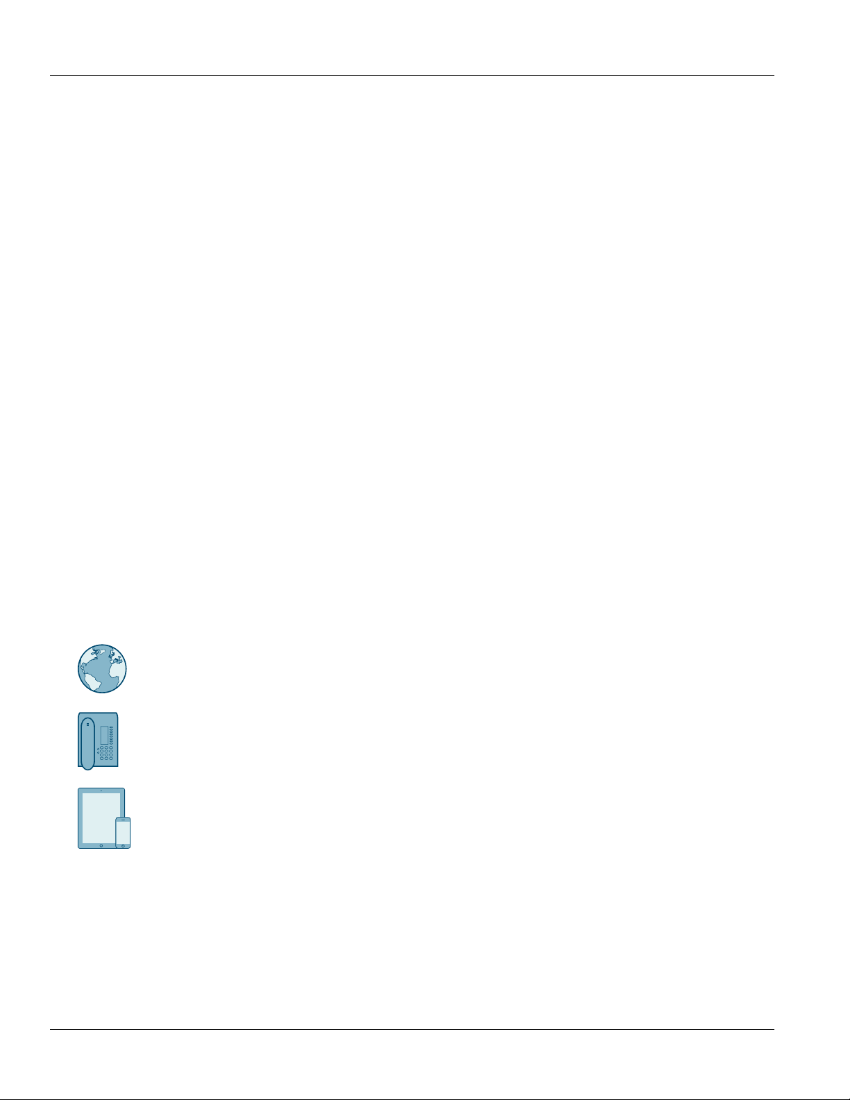
Online
Visit http://www.siemens.com/automation/support-request to submit a Support Request (SR) or check
on the status of an existing SR.
Telephone
Call a local hotline center to submit a Support Request (SR). To locate a local hotline center, visit http://
www.automation.siemens.com/mcms/aspa-db/en/automation-technology/Pages/default.aspx.
Mobile App
Install the Industry Online Support app by Siemens AG on any Android, Apple iOS or Windows mobile
device and be able to:
• Access Siemens' extensive library of support documentation, including FAQs and manuals
• Submit SRs or check on the status of an existing SR
• Contact a local Siemens representative from Sales, Technical Support, Training, etc.
• Ask questions or share knowledge with fellow Siemens customers and the support community
vi Related Documents

RUGGEDCOM RST2228
Installation Guide
Introduction
The RUGGEDCOM RST2228 is a utility grade, fully managed, industrial Ethernet switch designed to operate reliably
in harsh environments. With a rugged metal enclosure and an optional conformal coating, the RUGGEDCOM
RST2228 provides a high level of immunity to electromagnetic interference and heavy electrical surges, and can
withstand temperatures between -40 and 85 °C (-40 and 185 °F).
Highly modular, the RUGGEDCOM RST2228 switch supports up to 28 electrical and/or optical interfaces with data
transfer rates of 10/100/1000 Mbit/s. This makes it the ideal industry-standard switch for constructing electrical
and/or optical line, ring and star topologies.
The RUGGEDCOM RST2228 switch is supported by RUGGEDCOM ROS, which provides advanced Layer 2
networking functions, and advanced cyber security features.
CONTENTS
• Section1.1, “Feature Highlights”
Chapter 1
Introduction
• Section1.2, “Description”
• Section1.3, “Required Tools and Materials”
• Section1.4, “Decomissioning and Disposal”
• Section1.5, “Cabling Recommendations”
Section1.1
Feature Highlights
Extreme Flexibility
• Support for up to a total of 28 non-blocking ports (six 4-port modules and four fixed ports)
• Mixture of fiber optic or copper Gigabit ports with up to 28 Gig Ethernet ports, including 4 ports capable of 10
Gigabits.
• Galvanized steel and aluminum construction
Compact 1U Form Factor
• Space-saving design
Front Loading Modular Design
• Allows for simple, cost effective in-field servicing and upgrading
Dual Redundant Smart Power Supplies
• HI voltage AC/DC: 88-300 VDC or 85-264 VAC
• LO voltage DC: 10.5-15 VDC, 13-36 VDC or 36-72 VDC
• Smart power supplies able to detect loss of input voltage
Feature Highlights 1
Chapter 1
9
2
1
3
4
5
6
7
8
Introduction
Reliability in Harsh Environments
Installation Guide
• Immunity to EMI and heavy electrical surges
• Zero-Packet-Loss Technology
• Supports Siemens FastConnect RJ45 Cabling System
• -40 to 85 °C (-40 to 185 °F) operating temperature (fan-less)
• Conformal coated printed circuit boards (optional)
Section1.2
Description
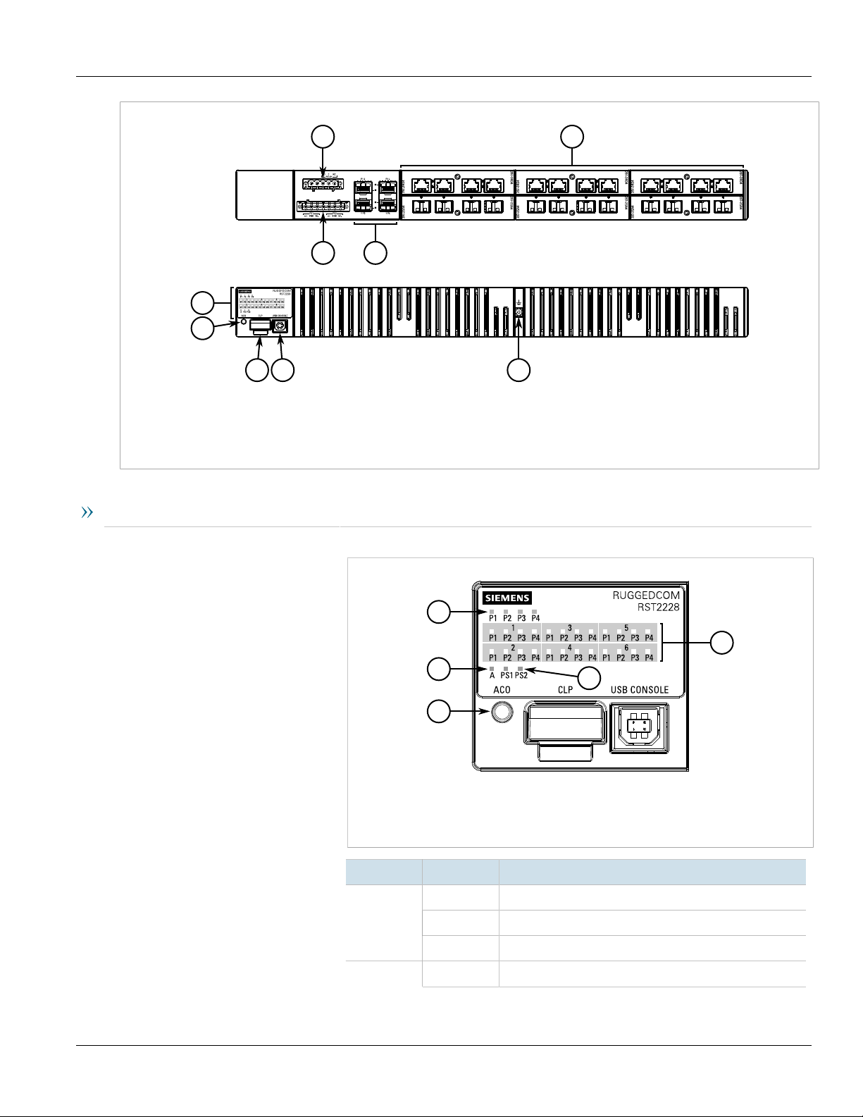
The RUGGEDCOM RST2228 features various ports, controls and indicator LEDs for connecting, configuring and
troubleshooting the device.
Orientation Options
The RUGGEDCOM RST2228 is available in one of two options:
• Option 1
Status panel, alarm LED, ACO Button, CLP port and USB console port are located on the front panel.
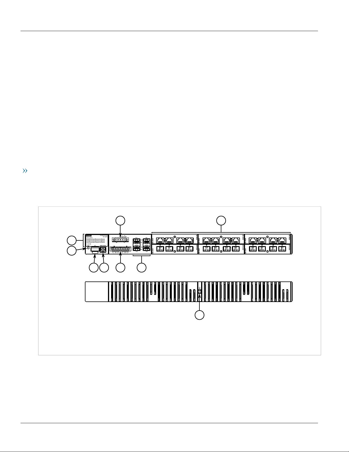
RUGGEDCOM RST2228
Figure1:RUGGEDCOM RST2228 (Front Panel Orientation)
1.Status Panel 2.ACO Button 3.CLP Port 4.USB Console Port 5.Failsafe Alarm Relay Terminal Block 6.Power Terminal Block
7.SFP/SFP+ Transceiver Sockets 8.Media Modules 9.Chassis Ground Terminal
• Option 2
Status panel, alarm LED, ACO Button, CLP port and USB console port are located on the rear panel.
2 Description
RUGGEDCOM RST2228
9
2
1
3
4
5
6
7
8
4
1
3
2
5
Installation Guide
Figure2:RUGGEDCOM RST2228 (Rear Panel Orientation)
1.Status Panel 2.ACO Button 3.CLP Port 4.USB Console Port 5.Failsafe Alarm Relay Terminal Block 6.Power Terminal Block
7.SFP/SFP+ Transceiver Sockets 8.Media Modules 9.Chassis Ground Terminal
Chapter 1
Introduction
Key Features
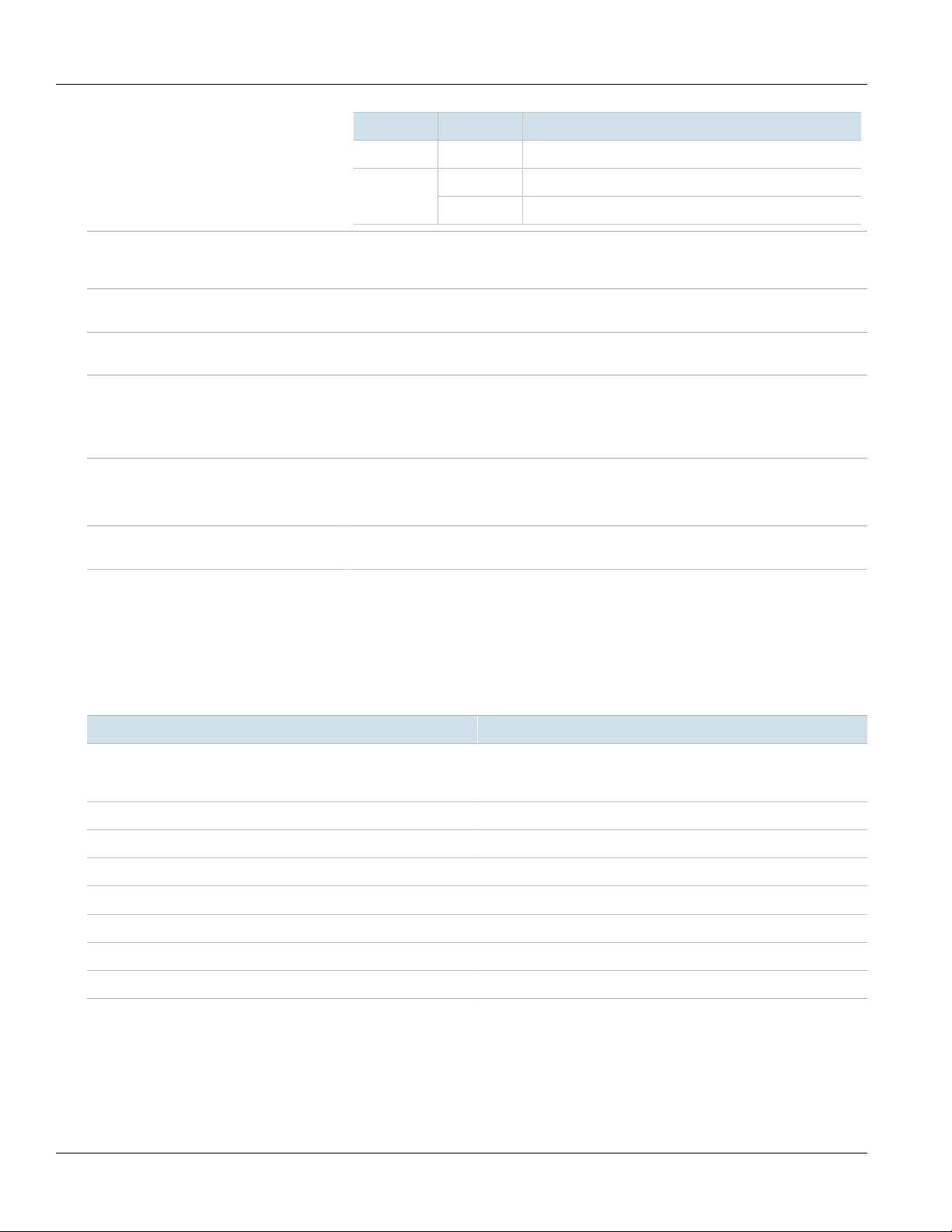
Status Panel The status panel displays the real-time status of the device.
Figure3:Status Panel
1.LEDs for 10GBase SFP+ Transceivers (Slot 0) 2.LEDs for Module ports 3.Alarm Status
LED 4.Power Supply Status LEDs 5.ACO Button
LED State Description
P{number}
Solid Link detected
Blinking Link activity
Description 3
A Solid An alarm condition exists
Off No link detected
Chapter 1
Introduction
RUGGEDCOM RST2228
Installation Guide
LED State Description
Off No active alarm conditions exist
Solid The power source is supplying power to the devicePS1/PS2
Off The power source is not supplying power to the device
USB Console Port The serial console port is for interfacing directly with the device and accessing initial
Alarm Indicator LED The alarm indicator LED illuminates when an alarm condition exists. Pressing the Alarm Cut-
Removable Media The device features sockets for up to four SFP/SFP+ transceivers and slots for up to six
Failsafe Alarm Relay Latches to default state when a power disruption or other alarm condition occurs. For more
Power Supply Terminal Block A pluggable terminal block. For more information, refer to:
Chassis Ground Terminal Protects the device from power surges and accumulated static electricity. For information
management functions. For information about connecting to the device via the serial
console port, refer to Section3.1, “Connecting to the Device”.
Off (ACO) button clears the alarm(s).
removable media modules. For more information, refer to Chapter4, Communication Ports.
information, refer to:
• Section2.4, “Connecting the Failsafe Alarm Relay”
• Section5.2, “Failsafe Alarm Relay Specifications”
• Section2.5, “Connecting Power”
• Section5.1, “Power Supply Specifications”
about grounding the device, refer to Section2.5, “Connecting Power”.
Section1.3
Required Tools and Materials
The following tools and materials are required to install the RUGGEDCOM RST2228:
Tools/Materials Purpose
AC/DC power cord For connecting power to the device. For the required. To determine
Lightning protector For protecting the device from harmful electrical strikes.
Flathead screwdriver For removing or installing modules and terminal blocks.
Torx T10 screwdriver For removing or installing modules.
Phillips screwdriver For removing or installing terminal blocks.
8 x M6 or #10-32 screws For mounting the device to a panel.
8 x M6 or #10-32 screws For mounting the device to a rack.
Braided or equivalent ground wire For grounding the device to safety Earth.
the proper wire gage, refer to Section5.1, “Power Supply
Specifications”.
4 Required Tools and Materials

RUGGEDCOM RST2228
Installation Guide
Section1.4
Decomissioning and Disposal
Proper decomissioning and disposal of this device is important to prevent malicious users from obtaining
proprietary information and to protect the environment.
Decommissioning
This device may include sensitive, proprietary data. Before taking the device out of service, either permanently or
for maintenance by a third-party, make sure it has been fully decommissioned.
For more information, refer to the associated User Guide.
Recycling and Disposal
For environmentally friendly recycling and disposal of this device and related accessories, contact a facility
certified to dispose of waste electrical and electronic equipment. Recycling and disposal must be done in
accordance with local regulations.
Chapter 1
Introduction
Section1.5
Cabling Recommendations
Siemens recommends using SIMATIC NET industrial Ethernet shielded cables for all Ethernet ports.
CONTENTS
• Section1.5.1, “Protection On Twisted-Pair Data Ports”
• Section1.5.2, “Gigabit Ethernet 1000Base-TX Cabling Recommendations”
• Section1.5.3, “Supported Fiber Optic Cables”
Section1.5.1
Protection On Twisted-Pair Data Ports
All copper Ethernet ports on RUGGEDCOM products include transient suppression circuitry to protect against
damage from electrical transients and conform with IEC 61850-3 and IEEE 1613 Class 1 standards. This means
that during a transient electrical event, communications errors or interruptions may occur, but recovery is
automatic.
Siemens also does not recommend using copper Ethernet ports to interface with devices in the field across
distances that could produce high levels of ground potential rise (i.e. greater than 2500 V), during line-to-ground
fault conditions.
Decomissioning and Disposal 5
Chapter 1
Introduction
RUGGEDCOM RST2228
Installation Guide
Section1.5.2
Gigabit Ethernet 1000Base-TX Cabling Recommendations
The IEEE 802.3ab Gigabit Ethernet standard defines 1000 Mbit/s Ethernet communications over distances of up
to 100 m (328 ft) using all 4 pairs in category 5 (or higher) balanced, unshielded twisted-pair cabling. For wiring
guidelines, system designers and integrators should refer to the Telecommunications Industry Association (TIA)
TIA/EIA-568-A wiring standard that characterizes minimum cabling performance specifications required for proper
Gigabit Ethernet operation. For reliable, error-free data communication, new and pre-existing communication
paths should be verified for TIA/EIA-568-A compliance.
The following table summarizes the relevant cabling standards:
Cabling Category
< 5 No New wiring infrastructure required.
5 Yes Verify TIA/EIA-568-A compliance.
5e Yes No action required. New installations should be designed with Category 5e or higher.
6 Yes No action required.
> 6 Yes Connector and wiring standards to be determined.
1000Base-
TX Compliant
Required Action
Follow these recommendations for copper data cabling in high electrical noise environments:
• Data cable lengths should be as short as possible, preferably 3 m (10 ft) in length. Copper data cables should
not be used for inter-building communications.
• Power and data cables should not be run in parallel for long distances, and should be installed in separate
conduits. Power and data cables should intersect at 90° angles when necessary to reduce inductive coupling.
• Shielded/screened cabling can be used when required. Care should be taken to avoid the creation of ground
loops with shielded cabling.
Section1.5.3
Supported Fiber Optic Cables
The following fiber optic cable types are supported under the stated conditions.
Cable Type Wavelength (nm)
a
a
a
Laser optimized.
850 200 — 275 33OM1 (62.5/125)
1300 500 2000 — —
850 500 — 550 82OM2 (50/125)
1300 500 2000 — —
850 1500 — 550 300OM3 (50/125)
1300 500 2000 — —
850 3500 — 550 400OM4 (50/125)
1300 500 2000 — —
Modal Bandwidth
(MHz·km)
100Base-FX 1000Base-SX 10GBase-SR
6 Gigabit Ethernet 1000Base-TX Cabling Recommendations
Distance (m)
RUGGEDCOM RST2228
Installation Guide
Installing the Device
This chapter describes how to install the device, including mounting the device, connecting power, and
connecting the device to the network.
DANGER!
Electrocution hazard – risk of serious personal injury and/or damage to equipment. Before performing
any maintenance tasks, make sure all power to the device has been disconnected and wait
approximately two minutes for any remaining energy to dissipate.
WARNING!
Radiation hazard – risk of serious personal injury. This product may contain a laser system and is
classified as a CLASS 1 LASER PRODUCT. Use of controls or adjustments or performance of procedures
other than those specified herein may result in hazardous radiation exposure.
Installing the Device
Chapter 2
IMPORTANT!
This product contains no user-serviceable parts. Attempted service by unauthorized personnel shall
render all warranties null and void.
Changes or modifications not expressly approved by Siemens Canada Ltd could invalidate
specifications, test results, and agency approvals, and void the user's authority to operate the
equipment.
IMPORTANT!
This product should be installed in a restricted access location where access can only be gained by
authorized personnel who have been informed of the restrictions and any precautions that must be
taken. Access must only be possible through the use of a tool, lock and key, or other means of security,
and controlled by the authority responsible for the location.
CONTENTS
• Section2.1, “General Procedure”
• Section2.2, “Unpacking the Device”
• Section2.3, “Mounting the Device”
• Section2.4, “Connecting the Failsafe Alarm Relay”
• Section2.5, “Connecting Power”
Section2.1
General Procedure
The general procedure for installing the device is as follows:
General Procedure 7
Chapter 2
Installing the Device
RUGGEDCOM RST2228
Installation Guide
IMPORTANT!
The user is responsible for the operating environment of the device, including maintaining the integrity
of all protective conductor connections and checking equipment ratings. Make sure to review all
operating and installation instructions before commissioning or performing maintenance on the
device.
1. Review the relevant certification information for any regulatory requirements.
For more information, refer to Section6.1, “Approvals”.
2. Review the RUGGEDCOM RST2228 Modules Catalog for special installation or regulatory requirements
related to the modules installed in the device.
For more information, refer to “Related Documents”.
3. Unpack and inspect the device.
For more information, refer to Section2.2, “Unpacking the Device”.
4. Mount the device.
For more information, refer to Section2.3, “Mounting the Device”.
5. Connect the failsafe alarm relay.
For more information, refer to Section2.4, “Connecting the Failsafe Alarm Relay”.
6. Connect power to the device and ground the device to safety Earth.
For more information, refer to Section2.5, “Connecting Power”.
7. Connect the device to the network.
For more information, refer to Chapter4, Communication Ports.
8. Configure the device.
For more information, refer to Section3.2, “Configuring the Device”.
Section2.2
Unpacking the Device
When unpacking the device, do the following:
1. Inspect the package for damage before opening it.
2. Visually inspect each item in the package for any physical damage.
3. Verify all items are included.
IMPORTANT!
If any item is missing or damaged, contact Siemens for assistance.
Section2.3
Mounting the Device
The RUGGEDCOM RST2228 is designed for maximum mounting and display flexibility. It can be ordered with
adapters that allow it to be installed in a 48 cm (19 in) rack or directly on a panel.
8 Unpacking the Device
RUGGEDCOM RST2228
1
2
Installation Guide
IMPORTANT!
Heat generated by the device is channeled outwards from the enclosure. As such, it is recommended
that 2.5 cm (1 in) of space be maintained on all open sides of the device to allow for some
convectional airflow.
Forced airflow is not required. However, any increase in airflow will result in a reduction of ambient
temperature and improve the long-term reliability of all equipment mounted in the rack space.
NOTE
For detailed dimensions of the device with either rack or panel hardware installed, refer to Section5.6,
“Dimension Drawings”.
CONTENTS
• Section2.3.1, “Mounting the Device to a Rack”
• Section2.3.2, “Mounting the Device to a Panel”
Section2.3.1
Installing the Device
Chapter 2
Mounting the Device to a Rack
The RUGGEDCOM RST2228 can be secured to a standard 48 cm (19 in) rack using separately purchased rack
mount adapters. The adapters can be installed at the front or rear of the chassis.
Each adapter kit includes four adapters.
To secure the device to a rack, do the following:
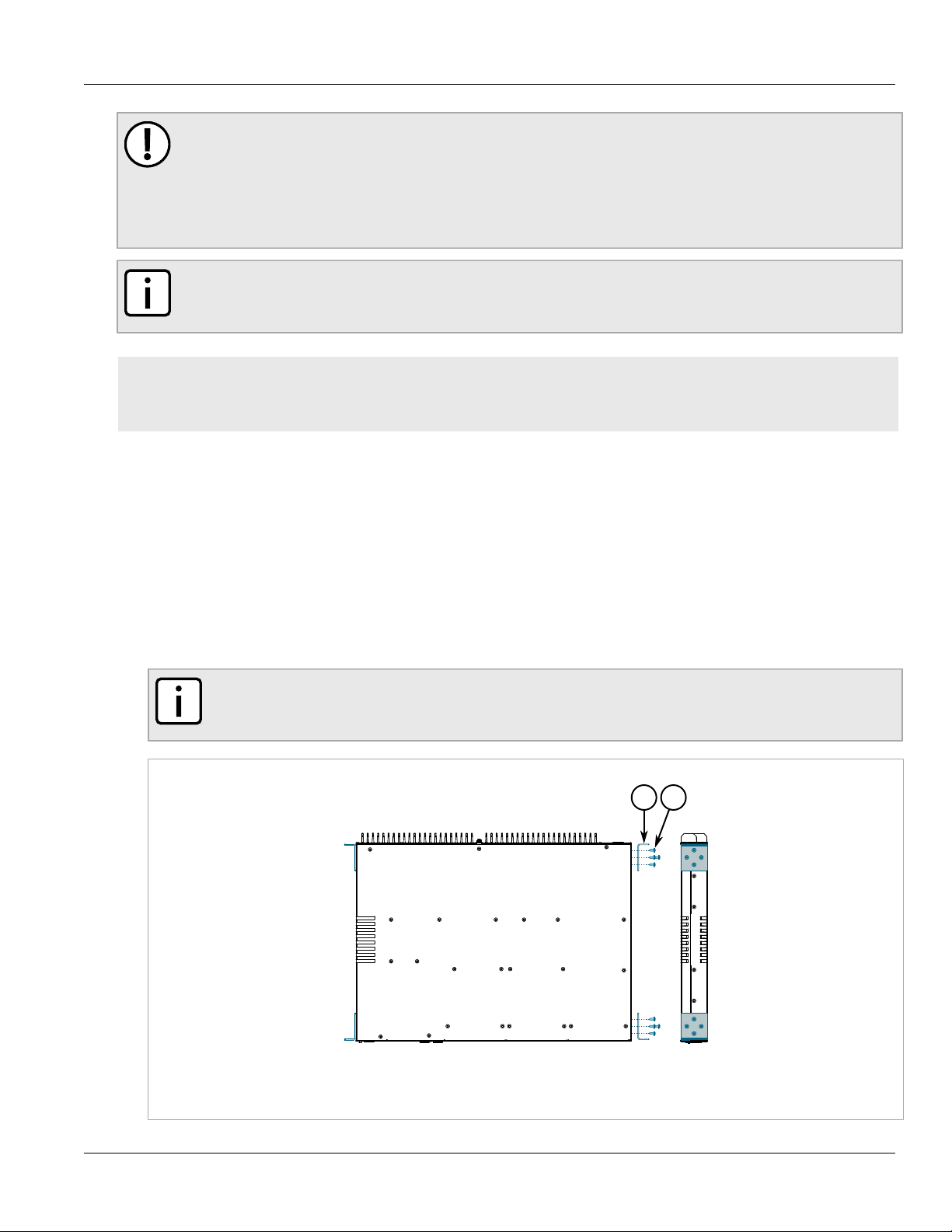
1. Secure the mounting adapters to both sides of the chassis.
NOTE
The chassis features multiple mounting holes, allowing the rack mount adapters to be installed up
to 25 mm (1 in) from the face of the device.
Figure4:Installing the Mounting Adapters
1.Mounting Adapter 2.Screw
Mounting the Device to a Rack 9
 Loading...