

Page 1
Preface
RUGGEDCOM RSG920P
Installation Guide
Introduction
Installing the Device
Communication Ports
Technical Specifications
Dimension Drawings
Certification
1
2
3
4
5
6
02/2016
RC1172-EN-04
Page 2

RUGGEDCOM RSG920P
Installation Guide
Copyright © 2016 Siemens Canada Ltd.
All rights reserved. Dissemination or reproduction of this document, or evaluation and communication of its contents, is not authorized
except where expressly permitted. Violations are liable for damages. All rights reserved, particularly for the purposes of patent application or
trademark registration.
This document contains proprietary information, which is protected by copyright. All rights are reserved. No part of this document may be
photocopied, reproduced or translated to another language without the prior written consent of Siemens Canada Ltd..
Disclaimer Of Liability
Siemens has verified the contents of this document against the hardware and/or software described. However, deviations between the
product and the documentation may exist.
Siemens shall not be liable for any errors or omissions contained herein or for consequential damages in connection with the furnishing,
performance, or use of this material.
The information given in this document is reviewed regularly and any necessary corrections will be included in subsequent editions. We
appreciate any suggested improvements. We reserve the right to make technical improvements without notice.
Registered Trademarks
RUGGEDCOM™ and ROS™ are trademarks of Siemens Canada Ltd..
Other designations in this manual might be trademarks whose use by third parties for their own purposes would infringe the rights of the
owner.
Third Party Copyrights
Siemens recognizes the following third party copyrights:
• Copyright © 2004 GoAhead Software, Inc. All Rights Reserved.
Security Information
Siemens provides products and solutions with industrial security functions that support the secure operation of plants, machines, equipment
and/or networks. They are important components in a holistic industrial security concept. With this in mind, Siemens' products and solutions
undergo continuous development. Siemens recommends strongly that you regularly check for product updates.
For the secure operation of Siemens products and solutions, it is necessary to take suitable preventive action (e.g. cell protection concept)
and integrate each component into a holistic, state-of-the-art industrial security concept. Third-party products that may be in use should also
be considered. For more information about industrial security, visit http://www.siemens.com/industrialsecurity.
To stay informed about product updates as they occur, sign up for a product-specific newsletter. For more information, visit http://
support.automation.siemens.com.
Warranty
Siemens warrants this product for a period of five (5) years from the date of purchase, conditional upon the return to factory for maintenance
during the warranty term. This product contains no user-serviceable parts. Attempted service by unauthorized personnel shall render all
warranties null and void. The warranties set forth in this article are exclusive and are in lieu of all other warranties, performance guarantees
and conditions whether written or oral, statutory, express or implied (including all warranties and conditions of merchantability and fitness for
a particular purpose, and all warranties and conditions arising from course of dealing or usage or trade). Correction of nonconformities in the
manner and for the period of time provided above shall constitute the Seller’s sole liability and the Customer’s exclusive remedy for defective
or nonconforming goods or services whether claims of the Customer are based in contract (including fundamental breach), in tort (including
negligence and strict liability) or otherwise.
ii
Page 3

RUGGEDCOM RSG920P
Installation Guide
Table of Contents
Table of Contents
Preface ............................................................................................................... vii
Alerts ................................................................................................................................................ vii
Related Documents ............................................................................................................................ vii
Accessing Documentation .................................................................................................................. viii
Training ............................................................................................................................................ viii
Customer Support ............................................................................................................................. viii
Chapter 1
Introduction .......................................................................................................... 1
1.1 Feature Highlights ........................................................................................................................ 1
1.2 Description .................................................................................................................................. 2
Chapter 2
Installing the Device ............................................................................................ 5
2.1 Required Tools and Materials ....................................................................................................... 6
2.2 Mounting the Device .................................................................................................................... 7
2.2.1 Mounting the Device on a DIN Rail .................................................................................... 7
2.2.2 Mounting the Device to a Panel ......................................................................................... 8
2.3 Connecting Power ........................................................................................................................ 9
2.3.1 Connecting High AC/DC Power ........................................................................................ 10
2.3.2 Connecting Low DC Power .............................................................................................. 10
2.3.3 Connecting an External PoE Power .................................................................................. 11
2.4 Grounding the Device ................................................................................................................. 13
2.5 Connecting the Failsafe Alarm Relay ........................................................................................... 13
2.6 Connecting the Digital Inputs ...................................................................................................... 14
2.7 Inserting/Removing the MicroSD Card ......................................................................................... 15
2.8 Connecting to the Device ........................................................................................................... 16
2.9 Gigabit Ethernet 1000Base-TX Cabling Recommendations ........................................................... 18
Chapter 3
Communication Ports ......................................................................................... 19
3.1 Copper Ethernet Ports ................................................................................................................ 19
3.2 SFP Optic Ethernet Ports ........................................................................................................... 21
3.2.1 Installing an SFP Optical Ethernet Port ............................................................................. 21
3.2.2 Removing an SFP Optical Ethernet Port ........................................................................... 22
v
Page 4

Table of Contents
RUGGEDCOM RSG920P
Installation Guide
3.3 PoE Ports .................................................................................................................................. 23
Chapter 4
Technical Specifications ..................................................................................... 25
4.1 Power Supply Specifications ....................................................................................................... 25
4.2 PoE Power Supply Specifications ................................................................................................ 25
4.3 Failsafe Alarm Relay Specifications ............................................................................................. 26
4.4 Copper Ethernet Port Specifications ............................................................................................ 26
4.5 SFP Optic Ethernet Port Specifications ........................................................................................ 26
4.6 Digital Input Specifications .......................................................................................................... 27
4.7 Operating Environment ............................................................................................................... 27
4.8 Mechanical Specifications ........................................................................................................... 28
Chapter 5
Dimension Drawings .......................................................................................... 29
Chapter 6
Certification ........................................................................................................ 33
6.1 Standards Compliance ............................................................................................................... 33
6.2 Agency Approvals ...................................................................................................................... 33
6.3 EMI and Environmental Type Tests ............................................................................................. 34
vi
Page 5
RUGGEDCOM RSG920P
Installation Guide
Preface
This guide describes the RUGGEDCOM RSG920P. It describes the major features of the device, installation,
commissioning and important technical specifications.
It is intended for use by network technical support personnel who are responsible for the installation,
commissioning and maintenance of the device. It is also recommended for use by network and system planners,
system programmers, and line technicians.
Alerts
The following types of alerts are used when necessary to highlight important information.
DANGER!
DANGER alerts describe imminently hazardous situations that, if not avoided, will result in death or
serious injury.
Preface
WARNING!
WARNING alerts describe hazardous situations that, if not avoided, may result in serious injury and/or
equipment damage.
CAUTION!
CAUTION alerts describe hazardous situations that, if not avoided, may result in equipment damage.
IMPORTANT!
IMPORTANT alerts provide important information that should be known before performing a procedure
or step, or using a feature.
NOTE
NOTE alerts provide additional information, such as facts, tips and details.
Related Documents
Other documents that may be of interest include:
• RUGGEDCOM ROS User Guide for the RSG920P
• RUGGEDCOM RPS1300 Operating Instructions (https://support.industry.siemens.com/cs/ww/en/
view/109478699)
Alerts vii
Page 6
Preface
RUGGEDCOM RSG920P
Installation Guide
Accessing Documentation
The latest user documentation for RUGGEDCOM RSG920P v is available online at
www.siemens.com/ruggedcom. To request or inquire about a user document, contact Siemens Customer
Support.
Training
Siemens offers a wide range of educational services ranging from in-house training of standard courses on
networking, Ethernet switches and routers, to on-site customized courses tailored to the customer's needs,
experience and application.
Siemens' Educational Services team thrives on providing our customers with the essential practical skills to make
sure users have the right knowledge and expertise to understand the various technologies associated with critical
communications network infrastructure technologies.
Siemens' unique mix of IT/Telecommunications expertise combined with domain knowledge in the utility,
transportation and industrial markets, allows Siemens to provide training specific to the customer's application.
For more information about training services and course availability, visit www.siemens.com/ruggedcom or
contact a Siemens sales representative.
Customer Support
Customer support is available 24 hours, 7 days a week for all Siemens customers. For technical support or
general information, contact Siemens Customer Support through any of the following methods:
Online
Visit http://www.siemens.com/automation/support-request to submit a Support Request (SR) or check
on the status of an existing SR.
Telephone
Call a local hotline center to submit a Support Request (SR). To locate a local hotline center, visit
http://www.automation.siemens.com/mcms/aspa-db/en/automation-technology/Pages/default.aspx.
Mobile App
Install the Industry Online Support app by Siemens AG on any Android, Apple iOS or Windows mobile
device and be able to:
• Access Siemens' extensive library of support documentation, including FAQs and manuals
• Submit SRs or check on the status of an existing SR
• Contact a local Siemens representative from Sales, Technical Support, Training, etc.
• Ask questions or share knowledge with fellow Siemens customers and the support community
viii Accessing Documentation
Page 7

RUGGEDCOM RSG920P
Installation Guide
Introduction
The RUGGEDCOM RSG920P is a rugged, high density, Ethernet switch designed to operate in harsh
environments with widely varying climatic and environmental conditions. Tested and certified to withstand
extreme temperatures, vibrations and shocks, the RUGGEDCOM RSG920P offers exceptional reliability for
industrial applications, such as transportation systems and oil/gas applications.
Offering 20 Gigabit Ethernet ports, including four SFP slots and four Power-over-Ethernet (PoE) ports, the
RUGGEDCOM RSG920P is suitable for applications that require high bandwidths and is ready to accommodate
future network expansions.
• The four SFP slots provide ultimate flexibility in up-link distances and bandwidth, with support for Gigabit and
Fast Ethernet.
• The four PoE ports supply up to 120 W (30 W per port) of power, allowing the RUGGEDCOM RSG920P to
accommodate various PoE devices, such as cameras, intercom devices, Wireless LAN Access points and
Bluetooth sensors. Smart Power Management options provide higher reliability for the most important devices
on the network when power demands exceed the available supply.
The small form factor of the RUGGEDCOM RSG920P allows for installation in space-limited cabinets and on DIN
rails.
RUGGEDCOM ROS provides advanced layer 2 networking functions, and advanced cyber security features.
Coupled with the ruggedized hardware design, RUGGEDCOM RSG920P is ideal for creating mission-critical,
real-time, control applications where high reliability and availability is of paramount importance.
The following sections provide more information about the RUGGEDCOM RSG920P:
• Section 1.1, “Feature Highlights”
• Section 1.2, “Description”
Chapter 1
Introduction
Section 1.1
Feature Highlights
Ethernet Ports and Inputs
• 16 x 10/100/1000Base-TX RJ-45 Ports
• 4 x 100/1000Base-TX/FX/SX/LX SFP Ports
NOTE
A separate power supply is required for PoE Ports
• 4 x IEEE 802.3at PoE (Power over Ethernet) Ports (30 W per port max, 120 W aggregate total)
• Two isolated digital inputs
Rated for Reliability in Harsh Environments
• Immunity to EMI and heavy electrical surges
• -40 to 85 °C (-40 to 185 °F) operating temperature (no fans)
• Conformal coated printed circuit boards (optional)
Feature Highlights 1
Page 8
Chapter 1
10
2
6
4
5
31
9
8
4
7
11
Introduction
Universal Power Supply Options
• Fully integrated power supply
• Universal high-voltage range: 98-300 VDC or 88-264 VAC
• Low-voltage DC input: 9-60 VDC
• Terminal blocks for reliable maintenance free connections
• CSA/UL 60950-1 safety approved to 85 °C (185 °F)
Section 1.2
Description
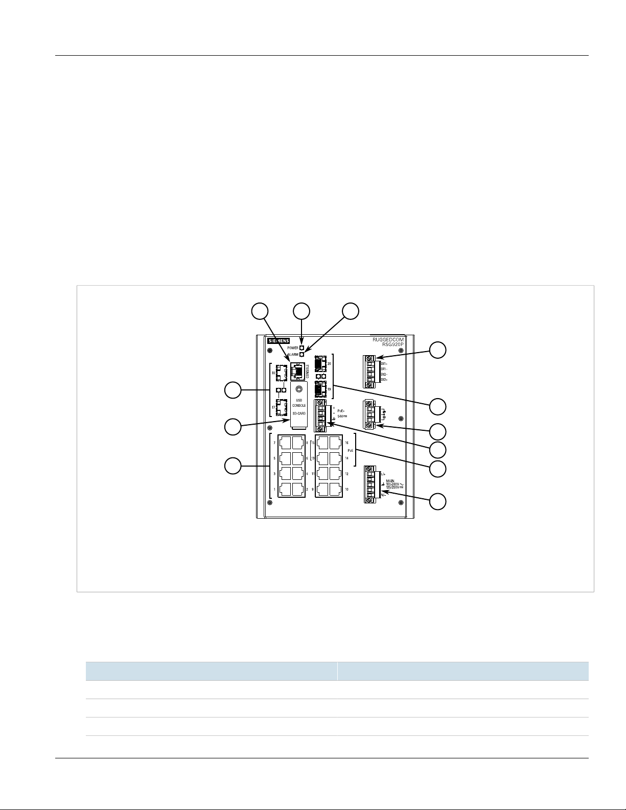
The RUGGEDCOM RSG920P features various ports, controls and indicator LEDs on the front panel for
connecting, configuring and troubleshooting the device.
RUGGEDCOM RSG920P
Installation Guide
Figure 1: RUGGEDCOM RSG920P
1. RS-232 Console Port (RJ45) 2. POWER LED 3. ALARM LED 4. SFP Ethernet Ports 5. Access Plate 6. 10/100/1000 Mbps
Copper Ethernet Ports 7. Digital Inputs 8. Failsafe Alarm Relay 9. PoE+ Power Input 10. PoE+ Ports 11. Main Power Supply
Terminal Block
• RS-232 Console Port – The serial console port is for interfacing directly with the device and accessing initial
management functions. For information about connecting to the device via the serial console port, refer to
Section 2.8, “Connecting to the Device”.
• POWER LED – Illuminates when power is being supplied to the device.
2 Description
Color Description
Green Device ready
Red Device booting up
Off No power
Page 9

RUGGEDCOM RSG920P
Installation Guide
• ALARM LED – Illuminates when an alarm condition exists.
• Port Status LEDs – Indicate the status of each port. For more information, refer to Chapter 3, Communication
Ports.
• Access Plate – The removable access plate provides access to the USB Type-B console port and microSD
slot.
▪ Use the USB console port to connect directly to the USB port on a workstation. For more information about
the USB console port, refer to Section 2.8, “Connecting to the Device”.
▪ Use a microSD card to load/store the firmware and configuration for the device. For information about using
a microSD card, refer to Section 2.7, “Inserting/Removing the MicroSD Card”.
• Digital Inputs – Two isolated independent digital inputs to monitor external equipment, such as a passive
switch or voltage provided by external equipment. For more information, refer to Section 2.6, “Connecting the
Digital Inputs”.
• Failsafe Alarm Relay – Latches to default state when a power disruption or other alarm condition occurs. For
more information, refer to:
▪ Section 2.5, “Connecting the Failsafe Alarm Relay”
▪ Section 4.3, “Failsafe Alarm Relay Specifications”
• Power Supply Terminal Block – A pluggable terminal block. For more information, refer to:
▪ Section 2.3, “Connecting Power”
▪ Section 4.1, “Power Supply Specifications”
Chapter 1
Introduction
Description 3
Page 10

RUGGEDCOM RSG920P
Installation Guide
Chapter 1
Introduction
Description 4
Page 11
RUGGEDCOM RSG920P
Installation Guide
Installing the Device
Installing the Device
The following sections describe how to install the device, including mounting the device, connecting power, and
connecting the device to the network.
DANGER!
Electrocution hazard – risk of serious personal injury and/or damage to equipment. Before performing
any maintenance tasks, make sure all power to the device has been disconnected and wait
approximately two minutes for any remaining energy to dissipate.
WARNING!
Radiation hazard – risk of serious personal injury. This product contains a laser system and is
classified as a CLASS 1 LASER PRODUCT. Use of controls or adjustments or performance of
procedures other than those specified herein may result in hazardous radiation exposure.
IMPORTANT!
This product contains no user-serviceable parts. Attempted service by unauthorized personnel shall
render all warranties null and void.
Changes or modifications not expressly approved by Siemens Canada Ltd. could invalidate
specifications, test results, and agency approvals, and void the user's authority to operate the
equipment.
Chapter 2
IMPORTANT!
This product should be installed in a restricted access location where access can only be gained
by authorized personnel who have been informed of the restrictions and any precautions that must be
taken. Access must only be possible through the use of a tool, lock and key, or other means of security,
and controlled by the authority responsible for the location.
IMPORTANT!
The RUGGEDCOM RSG920P may only be used for the applications described in the catalog and
in the relevant technical documentation. If products and components from other manufacturers are
used, these must be recommended/approved by Siemens. Proper transport, storage, installation,
assembly, commissioning, operation and maintenance are required to make sure the RUGGEDCOM
RSG920P operates properly and safely. The permissible ambient conditions must be complied with.
The information in the relevant document must be observed.
WARNING!
Fire/electrical/burn hazard – risk of serious personal injury and/or damage to the device. Do not use
any parts that show evidence of damage. If damaged parts are used, the device may not function
according to the specification. Damaged parts can lead to:
• Injury to personnel
• Loss of certification/approvals
• Violation of EMC regulations
• Damage to the device or other components
5
Page 12
Chapter 2
Installing the Device
IMPORTANT!
Do not install the RUGGEDCOM RSG920P in a nuclear power plant or other nuclear-related facilities.
IMPORTANT!
The RUGGEDCOM RSG920P must be located in an area accessible only by qualified service
personnel or other authorized users. Operation of the device is permitted only when this requirement is
met.
The general procedure for installing the device is as follows:
1. Mount the device to a rack or panel.
2. Connect power to the device and ground the device to safety Earth.
3. Connect the failsafe alarm relay.
4. Connect the digital inputs.
5. Connect the device to the network.
These steps, and other related information, are described in the following sections:
• Section 2.1, “Required Tools and Materials”
RUGGEDCOM RSG920P
Installation Guide
• Section 2.2, “Mounting the Device”
• Section 2.3, “Connecting Power”
• Section 2.4, “Grounding the Device”
• Section 2.5, “Connecting the Failsafe Alarm Relay”
• Section 2.6, “Connecting the Digital Inputs”
• Section 2.7, “Inserting/Removing the MicroSD Card”
• Section 2.8, “Connecting to the Device”
• Section 2.9, “Gigabit Ethernet 1000Base-TX Cabling Recommendations”
Section 2.1
Required Tools and Materials
The following tools and materials are required to install the RUGGEDCOM RSG920P:
Tools/Materials Purpose
RUGGEDCOM RPS1300 or equivalent 54 VDC output power supply For supplying PoE power to the device.
AC power cord (16 AWG) For connecting power to the device.
CAT-5 Ethernet cables For connecting the device to the network.
Flathead screwdriver For mounting the device to a DIN rail.
Phillips screwdriver For mounting the device to a panel.
4 x #8-32 screws For mounting the device to a panel.
6 Required Tools and Materials
Page 13
RUGGEDCOM RSG920P
2
1
Installation Guide
Section 2.2
Installing the Device
Mounting the Device
The RUGGEDCOM RSG920P is designed for maximum mounting and display flexibility. It can be equipped with
connectors that allow it to be installed in a 35 mm (1.4 in) DIN rail or directly on a panel.
IMPORTANT!
Heat generated by the device is channeled outwards to the enclosure. As such, it is recommended that
2.5 cm (1 in) of space be maintained on all open sides of the device to allow for some convectional
airflow.
Forced airflow is not required. However, any increase in airflow will result in a reduction of ambient
temperature and improve the long-term reliability of all equipment mounted in the rack space.
NOTE
For detailed dimensions of the device with either DIN rail or panel hardware installed, refer to
Chapter 5, Dimension Drawings.
The following sections describe the various methods of mounting the device:
• Section 2.2.1, “Mounting the Device on a DIN Rail”
• Section 2.2.2, “Mounting the Device to a Panel”
Chapter 2
Section 2.2.1
Mounting the Device on a DIN Rail
For DIN rail installations, the RUGGEDCOM RSG920P can be equipped with a DIN rail bracket that allows the
device to be slid onto a standard 35 mm (1.4 in) DIN rail.
To mount the device to a DIN rail, do the following:
1. Secure the DIN rail bracket to back of the device chassis.
Figure 2: DIN Rail Bracket Assembly
1. DIN Rail Bracket 2. Screw
2. Align the slot in the bracket with the DIN rail.
Mounting the Device 7
Page 14

Chapter 2
1
1
2
3
2
1
Installing the Device
Figure 3: DIN Rail Mounting
1. DIN Rail 2. DIN Rail Bracket
RUGGEDCOM RSG920P
Installation Guide
3. Pull the release on the bracket down and slide the device onto the DIN rail. Let go of the release to lock the
device in position.
Section 2.2.2
Mounting the Device to a Panel
For panel installations, the RUGGEDCOM RSG920P can be equipped with panel adapters that allow the device
to be attached to a panel in multiple orientations.
NOTE
A side mount orientation requires additional adapters.
Figure 4: Panel Mount Options
1. Rear Mount Orientation 2. Front Mount Orientation 3. Side Mount Orientation
8 Mounting the Device to a Panel
Page 15

RUGGEDCOM RSG920P
2
2
1 1
Installation Guide
Installing the Device
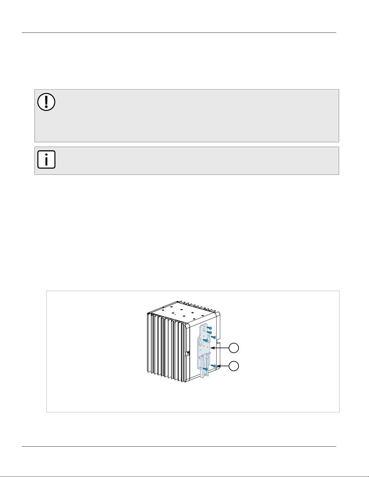
To mount the device to a panel, do the following:
1. Secure the adapters to the device in the desired orientation.
2. Place the device against (side or rear mount orientation) or insert it into (front mount orientation) the panel
and align the adapters with the mounting holes.
Chapter 2
Figure 5: Panel Mounting (Rear Mount Orientation Shown)
1. Screw 2. Panel Adapter
3. Install #8 screws (not supplied) to secure the adapters to the panel.
Section 2.3
Connecting Power
The RUGGEDCOM RSG920P supports a single integrated high AC/DC or low DC power supply, as well as an
external power supply for the Power-over-Ethernet (PoE) ports.
IMPORTANT!
• For 110/230 VAC rated equipment, an appropriately rated AC circuit breaker must be installed
• For 125/250 VDC rated equipment, an appropriately rated DC circuit breaker must be installed
• Equipment must be installed according to applicable local wiring codes and standards
• Use only #16 gage copper wiring when connecting terminal blocks
The following sections describe how to connect power to the device:
• Section 2.3.1, “Connecting High AC/DC Power”
• Section 2.3.2, “Connecting Low DC Power”
• Section 2.3.3, “Connecting an External PoE Power”
Connecting Power 9
Page 16

Chapter 2
2 3 4
1
Installing the Device
Section 2.3.1
RUGGEDCOM RSG920P
Installation Guide
Connecting High AC/DC Power
To connect a high AC/DC power supply to the device, do the following:
CAUTION!
Electrical hazard – risk of damage to equipment. Do not connect AC power cables to terminals for DC
power. Damage to the power supply may occur.
1. Secure a European-style terminal block (or Euroblock) to the terminal.
2. Connect the live/positive wire from the power source to the live/positive (L/+) terminal on the terminal block.
Figure 6: Terminal Block Wiring
1. Main Power Terminal Block 2. Neutral/Negative (N/-) Terminal 3. Chassis Ground Terminal 4. Live/Positive (L/+) Terminal
3. Connect the neutral/negative wire from the power source to the neutral/negative (N/-) terminal on the
terminal block.
4. Connect the ground wire to the chassis ground terminal on the device.
Section 2.3.2
Connecting Low DC Power
To connect a single or dual power sources to the low DC power supply, do the following:
IMPORTANT!
When connecting two external power sources, if the first external power source has a voltage lower
than 33 VDC, the second power source must have a voltage lower than 33 VDC as well. Similarly,
if the first power source has a voltage higher than 36 VDC, the second power source must have a
voltage higher than 36 VDC.
1. Connect the positive wire from the power source to the positive terminal on the terminal block.
10 Connecting High AC/DC Power
Page 17

RUGGEDCOM RSG920P
1
243
1
2
4
2
3 3
Installation Guide
Figure 7: Terminal Block Wiring - Connecting a Single DC Power Supply Input
1. Main Power Terminal Block 2. Chassis Ground Terminal 3. Negative Terminal 4. Positive Terminal
Installing the Device
Chapter 2
Figure 8: Terminal Block Wiring - Connecting Dual DC Power Supply Inputs
1. Main Power Terminal Block 2. Positive Terminal 3. Negative Terminal 4. Chassis Ground Terminal
2. Connect the negative wire from the power source to the negative terminal on the terminal block.
3. Connect the ground wire to the chassis ground terminal on the device.
Section 2.3.3
Connecting an External PoE Power
The RUGGEDCOM RSG920P supports four 10/100/1000 Mbps Power-over-Ethernet (POE) Ports that require
external power.
Connecting an External PoE Power 11
Page 18

Chapter 2
1
3
4
2
Installing the Device
RUGGEDCOM RSG920P
Installation Guide
NOTE
Siemens recommends using the RUGGEDCOM RPS1300 switch-mode AC power supply. For
more information about this power supply, refer to https://support.industry.siemens.com/cs/ww/en/
view/109478699.
To support the IEEE 802.3at specification (30 W/port output), the external power supply must meet the following
requirements:
Power Supply Type
DC 51 VDC 57 VDC 1.5 kVAC/2.2 kVDC 135 W
Input Range
Isolation
Minimum Maximum
Minimum
Power Required
To support the IEEE 802.3af specification (15 W/port output), the external power supply must meet the following
requirements:
Power Supply Type
DC 45 VDC 57 VDC 1.5 kVAC/2.2 kVDC 75 W
Input Range
Isolation
Minimum Maximum
Minimum
Power Required
To connect an external power supply for the PoE ports, do the following:
1. Secure a European-style terminal block (or Euroblock) to the terminal.
Figure 9: Terminal Block Wiring
1. PoE Terminal Block 2. Chassis Ground 3. Negative Terminal 4. Positive Terminal
2. Connect the positive wire from the RUGGEDCOM RPS1300 (or another external power supply) to the
positive (+) terminal on the terminal block.
3. Connect the negative wire from the RUGGEDCOM RPS1300 (or another external power supply) to the
negative (-) terminal on the terminal block.
4. If using an external power supply other than the RUGGEDCOM RPS1300 that has a chassis ground
connection, connect the ground terminal on the power supply to the chassis ground terminal on the device.
12 Connecting an External PoE Power
Page 19

RUGGEDCOM RSG920P
2
3
1
Installation Guide
Section 2.4
Installing the Device
Grounding the Device
The RUGGEDCOM RSG920P chassis features a threaded hole for connecting the device to ground (Protective
Earth). It is recommended to terminate the ground connection with an M3 ring or spade lug, and then torque to
1.7 N·m (15 lbf-in).
Chapter 2
Figure 10: Chassis Ground Connection
1. Chassis Ground Connection 2. M3 Ring Lug 3. M3 Screw
Section 2.5
Connecting the Failsafe Alarm Relay
The failsafe alarm relay can be configured to latch based on alarm conditions. The NO (Normally Open) contact
is closed when the unit is powered and there are no active alarms. If the device is not powered or if an active
alarm is configured, the relay opens the NO contact and closes the NC (Normally Closed) contact.
NOTE
Control of the failsafe alarm relay output is configurable through ROS. One common application for this
relay is to signal an alarm if a power failure occurs. For more information, refer to the ROS User Guide
for the RUGGEDCOM RSG920P.
The following shows the proper relay connections.
Grounding the Device 13
Page 20

Chapter 2
3
2 4
1
Installing the Device
Figure 11: Failsafe Alarm Relay Wiring
1. Failsafe Alarm Relay Terminal 2. Normally Open Terminal 3. Common Terminal 4. Normally Closed Terminal
RUGGEDCOM RSG920P
Installation Guide
Section 2.6
Connecting the Digital Inputs
The RUGGEDCOM RSG920P offers two independent digital inputs for monitoring external equipment.
Each digital input is associated with an alarm that is configured in RUGGEDCOM ROS. Depending on the
configuration, the associated alarm may be triggered if the digital input is in either the HIGH or LOW state.
Each input operates in one of two modes:
• Passive Mode
Supports the use of passive switches, such as a cabinet door switch, relay or a leak detector, where each
digital input detects if it is open or closed.
• Direct Mode
Supports direct inputs from external equipment. A voltage between 10 and 30 V indicates state 1, while a
voltage between -30 and 8 V indicates state 0. In the undetermined range between 8 and 10 V, the input may
be determined to be in either state.
The nominal input voltage is 24 VDC.
NOTE
For information about configuring the digital input alarms, refer to the RUGGEDCOM ROS User Guide
for the RUGGEDCOM RSG920P.
NOTE
For technical specifications related to the digital input ports, refer to Section 4.6, “Digital Input
Specifications”.
To connect a digital input, do the following:
1. Secure a European-style terminal block (or Euroblock) to the terminal.
2. Connect the positive cable to the DI1/2+ terminal.
14 Connecting the Digital Inputs
Page 21

RUGGEDCOM RSG920P
4 5
2
3
1
Installation Guide
Figure 12: Terminal Block Wiring
1. Digital Input Terminal Block 2. DI2+ Terminal 3. DI2- Terminal 4. DI1- Terminal 5. DI1+ Terminal
Installing the Device
Chapter 2
3. Connect the negative cable to the DI1/2- terminal.
Section 2.7
Inserting/Removing the MicroSD Card
The RUGGEDCOM RSG920P accepts a microSD card for storing configuration files and/or software updates.
CAUTION!
Configuration hazard – risk of data loss. The microSD card must not be removed or replaced while the
device is booting up or when configuration changes are being made. Information on the microSD card
may be lost. Make sure the device is powered down before removing or inserting the card.
CAUTION!
Mechanical/electrical hazard – risk of damage to the microSD card.
• Do not expose the microSD car to extreme temperatures or humidity.
• Do not expose the microSD card to large magnetic or static electric fields.
• Do not bend or drop the microSD card.
CAUTION!
Security hazard – risk of unauthorized access and/or exploitation. Make sure to remove the microSD
card before decommissioning the device or sending the device to a third-party.
To insert or remove a microSD card, do the following:
1. Unscrew the retention screw and remove the access plate.
Inserting/Removing the MicroSD Card 15
Page 22

Chapter 2
2
1
Installing the Device
Figure 13: Inserting/Removing a MicroSD Card
1. MicroSD Card 2. Access Plate
RUGGEDCOM RSG920P
Installation Guide
2. When removing the card, first press the card in until it springs back.
3. Without touching the contacts on the card, insert or remove the microSD card.
4. When installing the card, push the card in until it clicks in place.
5. Install the access plate and tighten the retention screw.
6. Power up the device.
Section 2.8
Connecting to the Device
The following describes the various methods for accessing the ROS console and Web interfaces on the device.
For more detailed instructions, refer to the ROS User Guide for the RUGGEDCOM RSG920P.
RS-232 Console Port
Connect a workstation directly to either the RJ-45 or USB Type-B console port to access the boot-time control
and ROS interfaces. Both console ports provide access to ROS's console and Web interfaces.
IMPORTANT!
Console ports are intended to be used only as a temporary connection during initial configuration or
troubleshooting.
NOTE
When the USB Type-B console port is in use, the RJ-45 console port will echo the console output but
not accept any user input.
16 Connecting to the Device
Page 23

RUGGEDCOM RSG920P
3
2
1
1
8
Installation Guide
Installing the Device
Chapter 2
NOTE
For Microsoft Windows users, the RUGGEDCOM USB Serial Console driver must be installed on the
users workstation before connecting via the USB Type-B console port. For more information, refer to
the RUGGEDCOM ROS User Guide for the RUGGEDCOM RSG920P.
Figure 14: Console Ports
1. RJ-45 Console Port 2. USB Type-B Console Port 3. Access Plate
Connection to the RJ-45 console port is made using an RJ45-to-DB9 console cable. The following is the pin-out
for the RJ-45 console port:
Pin
Name Description
a
a
a
Data Set Ready
Carrier Detect
Data Terminal Ready
(from DTE)
c
c
d
Clear to Send
Read to Send
Ring Indicator
Figure 15: RJ-45 Console Port Pin Configuration
a
The DSR, DCD and DTR pins are connected together internally.
b
Reserved (do not connect)
c
The CTS and RTS pins are connected together internally.
d
RI is not connected.
RJ-45
Male
DB9
Female
1 6 DSR
b
2
1 DCD
3 4 DTR
4 5 GND Signal Ground
5 2 RxD Receive Data (to DTE)
6 3 TxD Transmit Data
7 8 CTS
8 7 RTS
9 RI
Connecting to the Device 17
Page 24

Chapter 2
Installing the Device
RUGGEDCOM RSG920P
Installation Guide
Communication Ports
Connect any of the available Ethernet ports on the device to a management switch and access the ROS console
and Web interfaces via the device's IP address. For more information about available ports, refer to Chapter 3,
Communication Ports.
Section 2.9
Gigabit Ethernet 1000Base-TX Cabling Recommendations
The IEEE 802.3ab Gigabit Ethernet standard defines 1000 Mbps Ethernet communications over distances of up
to 100 m (328 ft) using all 4 pairs in category 5 (or higher) balanced, unshielded twisted-pair cabling. For wiring
guidelines, system designers and integrators should refer to the Telecommunications Industry Association (TIA)
TIA/EIA-568-A wiring standard that characterizes minimum cabling performance specifications required for proper
Gigabit Ethernet operation. For reliable, error-free data communication, new and pre-existing communication
paths should be verified for TIA/EIA-568-A compliance.
The following table summarizes the relevant cabling standards:
Cabling Category
< 5 No New wiring infrastructure required.
5 Yes Verify TIA/EIA-568-A compliance.
5e Yes No action required. New installations should be designed with Category 5e or higher.
6 Yes No action required.
> 6 Yes Connector and wiring standards to be determined.
1000Base-
TX Compliant
Required Action
Follow these recommendations for copper data cabling in high electrical noise environments:
• Data cable lengths should be as short as possible, preferably 3 m (10 ft) in length. Copper data cables should
not be used for inter-building communications.
• Power and data cables should not be run in parallel for long distances, and should be installed in separate
conduits. Power and data cables should intersect at 90° angles when necessary to reduce inductive coupling.
• Shielded/screened cabling can be used when required. Care should be taken to avoid the creation of ground
loops with shielded cabling.
18
Gigabit Ethernet 1000Base-TX Cabling
Recommendations
Page 25

RUGGEDCOM RSG920P
3
2
1
1
Installation Guide
Communication Ports
Communication Ports
The RUGGEDCOM RSG920P can be equipped with various types of communication ports to enhance its abilities
and performance.
Chapter 3
Figure 16: Port Assignment
1. SFP Ethernet Ports 2. Copper Ethernet Ports 3. PoE+ Ports
Port Type
1 to 16 10/100/1000 Mbps Copper Ethernet Ports
13 to 16 10/100/1000 Mbps Power-over-Ethernet (POE) Ports
17 to 20 SFP up-link ports supporting Fast Ethernet or Gigabit Ethernet optics (used
The following sections describe the available ports:
• Section 3.1, “Copper Ethernet Ports”
• Section 3.2, “SFP Optic Ethernet Ports”
• Section 3.3, “PoE Ports”
Section 3.1
Copper Ethernet Ports
The RUGGEDCOM RSG920P supports several 10/100/1000Base-TX Ethernet ports that allow connection
to standard Category 5 (CAT-5) unshielded twisted-pair (UTP) cables with RJ45 male connectors. The RJ45
connectors are directly connected to the chassis ground on the device and can accept CAT-5 shielded twistedpair (STP) cables.
interchangeably)
Copper Ethernet Ports 19
Page 26

Chapter 3
1
1
1
8
Communication Ports
WARNING!
Electric shock hazard – risk of serious personal injury and/or equipment interference. If shielded
cables are used, make sure the shielded cables do not form a ground loop via the shield wire and the
RJ45 receptacles at either end. Ground loops can cause excessive noise and interference, but more
importantly, create a potential shock hazard that can result in serious injury.
LEDs
Each port features an LED that indicates the link/activity state of the port.
State Description
Green (Solid) Link established
Green (Blinking) Link activity
Off No link detected
Figure 17: RJ45 Port LEDs
1. Link/Activity LED
RUGGEDCOM RSG920P
Installation Guide
Pin-Out
The following is the pin-out for the RJ45 male connectors:
Figure 18: RJ45 Ethernet Port Pin Configuration
Pin
10/100Base-TX 1000Base-TX
1 RX+ BI_DB+ Receive Data+
2 RX- BI_DB- Receive Data-
3 TX+ BI_DA+ Transmit Data+
4 Reserved (Do
Not Connect)
5 Reserved (Do
Not Connect)
6 TX- BI_DA- Transmit Data-
7 Reserved (Do
Not Connect)
8 Reserved (Do
Not Connect)
Name
Description
or Bi-Directional
or Bi-Directional
or Bi-Directional
BI_DD+ Bi-Directional
BI_DD- Bi-Directional
or Bi-Directional
BI_DC+ Bi-Directional
BI_DC- Bi-Directional
Specifications
For specifications on the available copper Ethernet ports, refer to Section 4.4, “Copper Ethernet Port
Specifications”.
20 Copper Ethernet Ports
Page 27

RUGGEDCOM RSG920P
21
Installation Guide
Section 3.2
Communication Ports
SFP Optic Ethernet Ports
The RUGGEDCOM RSG920P supports up to four SFP (Small Form-Factor Pluggable) optic Ethernet ports with
LC (Lucent Connector) connectors. Make sure the Transmit (Tx) and Receive (Rx) connections of each port are
properly connected and matched to establish a proper link.
Figure 19: LC Port
1. Tx Connector 2. Rx Connector
LEDs
Each port features an LED that indicates the state of the port.
Chapter 3
State Description
Green (Solid) Link established
Green (Blinking) Link activity
Off No link detected
Specifications
For specifications on the available SFP optic Ethernet ports, refer to Section 4.5, “SFP Optic Ethernet Port
Specifications”.
Installation/Removal
The following sections describe how to install and remove SFP optical ports:
NOTE
SFP optical ports can be safely inserted and removed while the chassis is powered and operating.
• Section 3.2.1, “Installing an SFP Optical Ethernet Port”
• Section 3.2.2, “Removing an SFP Optical Ethernet Port”
Section 3.2.1
Installing an SFP Optical Ethernet Port
To install an SFP optical Ethernet port, do the following:
SFP Optic Ethernet Ports 21
Page 28

Chapter 3
2
1
Communication Ports
CAUTION!
Electrical hazard – risk of damage to equipment. Use only components certified by Siemens with
RUGGEDCOM products. Damage to the device may occur if compatibility and reliability have not been
properly assessed.
CAUTION!
Electrical hazard – risk of damage to equipment. Make sure all electrostatic energy is dissipated
before installing or removing components from the device. An electrostatic discharge (ESD) can cause
serious damage to the component once it is outside the chassis.
1. Make sure all potential electrostatic build-up has been properly discharged to prevent electrostatic
discharges (ESD). This can be accomplished by wearing an ESD wrist strap or by touching Earth or the
chassis ground.
2. Remove the dust cover from the port opening in the device.
CAUTION!
Mechanical hazard – risk of component damage. SFP optical Ethernet ports are designed to insert
in only one orientation. Do not force the SFP port into the device.
3. Remove the SFP port from its packaging.
4. Insert the SFP port into the device and swing the bail-latch up to lock it in place.
RUGGEDCOM RSG920P
Installation Guide
Figure 20: Installing an SFP Optical Ethernet Port (Typical)
1. SFP Optical Ethernet Port 2. Metal Bail-Latch
5. Connect a cable to the SFP port and test the connection.
Section 3.2.2
Removing an SFP Optical Ethernet Port
To remove an SFP optical Ethernet port, do the following:
CAUTION!
Electrical hazard – risk of damage to equipment. Make sure all electrostatic energy is dissipated before
performing installing or removing components from the device. An electrostatic discharge (ESD) can
cause serious damage to the component once it is outside the chassis.
1. Make sure all potential electrostatic build-up has been properly discharged to prevent electrostatic
discharges (ESD). This can be accomplished by wearing an ESD wrist strap or by touching Earth or the
chassis ground.
2. Disconnect the cable from the SFP port.
22 Removing an SFP Optical Ethernet Port
Page 29

RUGGEDCOM RSG920P
2
1
2
1
2
1
Installation Guide
Communication Ports
3. Pull down the metal bail-latch on the SFP port and remove the port from the device.
Figure 21: Removing an SFP Optical Ethernet Port (Typical)
1. SFP Optical Ethernet Port 2. Metal Bail-Latch
4. Store the SFP port in an ESD-safe bag or other suitable ESD-safe environment, free from moisture and
stored at the proper temperature (-40 to 85 °C or -40 to 185 °F).
5. Install a dust cover in the port opening in the device to prevent the ingress of moisture, dirt and debris.
Section 3.3
Chapter 3
PoE Ports
The RUGGEDCOM RSG920P supports four Power over Ethernet (POE) ports (ports 13 to 16) powered by an
external power supply. Each port complies with the IEEE 802.3at standard.
The total allowable power budget for all ports is 120 W. If the external power supply is less than 120 W, to prevent
exceeding the power budget, port priorities can be set via the RUGGEDCOM ROS operating system to disable
low priority ports when demand is too high. Ports can also be enabled/disabled and placed on a power schedule
to conserve power. For more information, refer to the RUGGEDCOM ROS User Guide for the RUGGEDCOM
RSG920P.
For information about connecting the external power supply, refer to Section 2.3.3, “Connecting an External PoE
Power”.
LEDs
Each PoE port features an LED that indicates the power state of the port and link status.
LED State Description
Green (Solid) Link established
Green (Blinking) Link activity
Off No link detected
Yellow (Solid) Power provided
Yellow (Blinking) Searching for load
Figure 22: RJ-45 Port LEDs
1. Link/Activity LED 2. Power State LED
Link/Activity
Power State
Off No power or port
PoE Ports 23
disabled
Page 30

Chapter 3
1
8
Communication Ports
Pin-Out
The pin-out for the PoE ports is as follows:
NOTE
Ports 13 and 15 are wired per IEEE 802.3at Alternative-A, while ports 14 and 16 are wired per IEEE
802.3at Alternative-B.
Pin
10/100Base-
TX
Name PoE Voltage 54 V Nominal
1000Base-TX
Ports 13
and 15
Ports 14
and 16
RUGGEDCOM RSG920P
Installation Guide
Description
Figure 23: PoE Port Pin
Configuration
Specifications
1 RX+ BI_DB+ V+ Receive
2 RX- BI_DB- V+ Receive
3 TX+ BI_DA+ V- Transmit
4 Reserved (Do
Not Connect)
5 Reserved (Do
Not Connect)
6 TX- BI_DA- V- Transmit
7 Reserved (Do
Not Connect)
8 Reserved (Do
Not Connect)
BI_DD+ V+ Bi-Directional
BI_DD- V+ Bi-Directional
BI_DC+ V- Bi-Directional
BI_DC- V- Bi-Directional
Data+ or Bi-
Directional
Data- or Bi-
Directional
Data+ or Bi-
Directional
Data- or Bi-
Directional
For specifications on the available PoE ports, refer to Section 4.2, “PoE Power Supply Specifications”.
24 PoE Ports
Page 31

RUGGEDCOM RSG920P
Installation Guide
Technical Specifications
The following sections provide important technical specifications related to the device:
• Section 4.1, “Power Supply Specifications”
• Section 4.2, “PoE Power Supply Specifications”
• Section 4.3, “Failsafe Alarm Relay Specifications”
• Section 4.4, “Copper Ethernet Port Specifications”
• Section 4.5, “SFP Optic Ethernet Port Specifications”
• Section 4.6, “Digital Input Specifications”
• Section 4.7, “Operating Environment”
• Section 4.8, “Mechanical Specifications”
Technical Specifications
Chapter 4
Section 4.1
Power Supply Specifications
Power Supply Type
HI
LO 9 VDC 60 VDC 5 A 1.5 kVDC
a
(T) denotes time-delay fuse.
b
Power consumption varies based on configuration.
Section 4.2
Input Range
Minimum Maximum
98 VDC 300 VDC
88 VAC 264 VAC
Internal
Fuse Rating
3.15 A(T) 2.8 kVAC
a
Isolation
Maximum Power
Consumption
PoE Power Supply Specifications
The RUGGEDCOM RSG920P adheres to the following power output and IEEE specifications depending on the
input voltage supplied to the device.
Power In
Voltage Range Internal Fuse Rating
Power Out
b
27 W
51-57 VDC 50-57 VDC, 30 W per Port Maximum (IEEE 302.at)
45-57 VDC
Power Supply Specifications 25
3.15 A Maximum
44-57 VDC, 15 W per Port Maximum (IEEE 302.af)
Page 32

Chapter 4
Technical Specifications
Section 4.3
Failsafe Alarm Relay Specifications
Maximum Switching Voltage Rated Switching Current Isolation
RUGGEDCOM RSG920P
Installation Guide
30 VDC
250 VAC
2.0 A 2.0 kVAC (1 min)
Section 4.4
Copper Ethernet Port Specifications
The following details the specifications for copper Ethernet ports that can be ordered with the RUGGEDCOM
RSG920P.
Speed
c
(Mbps)
10/100/1000 TX RJ45 FDX/HDX > CAT-5
c
Auto-negotiating.
d
Shielded or unshielded.
e
Auto-crossover and auto-polarity.
f
Typical distance. Dependent on the number of connectors and splices.
g
RMS 1 minute.
Interface Connector Duplex
c
Cable Type
d
Wiring
Standard
TIA/EIA
T568A/B
Maximum
e
Distance
100 m (328 ft) 1.5 kVAC
f
Isolation
g
Section 4.5
SFP Optic Ethernet Port Specifications
The RUGGEDCOM RSG920P features four 100/1000Base-FX Small Form-Factor Pluggable (SFP) optic
Ethernet ports with LC (Lucent Connector) connectors. For more information about the SFP ports, refer to
Section 3.2, “SFP Optic Ethernet Ports”.
NOTE
• Maximum segment length is greatly dependent on factors such as fiber quality, and the number
of patches and splices. Consult a Siemens sales associate when determining maximum segment
distances.
• All optical power numbers are listed as dBm averages.
Speed
(Mbit/s)
100
n
100
Connector
Interface Mode
l
FX MM LC
FX SM LC 9/125 1300 -15 -8 -34 -8 20 19
h
Type
Cable
Type
(μm)
62.5/125
50/125
Tx/Rx
λ (nm)
1310 -19 -14 -32 -14 2 13
Minimum
i
(dBm)
Tx
Maximum
j
(dBm)
Tx
Rx
Sensitivity
j
(dBm)
Rx
Saturation
j
(dBm)
Distance
j
(km)
k
Power
Budget
(dB)
Criteria
m
A
26 Failsafe Alarm Relay Specifications
Page 33

RUGGEDCOM RSG920P
Installation Guide
Technical Specifications
Chapter 4
Speed
(Mbit/s)
1000
Interface Mode
l
SX MM LC
Connector
h
Type
Cable
Type
(μm)
62.5/125
Tx/Rx
λ (nm)
850 -9 -2.5 -20 0 0.5 11
Minimum
i
(dBm)
Tx
Maximum
j
(dBm)
Tx
Rx
Sensitivity
j
(dBm)
Rx
Saturation
j
(dBm)
Distance
j
(km)
k
Power
Budget
(dB)
Criteria
50/125
l
1000
1000
1000
h
MM = Multi-Mode, SM = Single-Mode
i
Typical.
j
All optical power numbers are listed as dBm averages.
k
Typical distance. The maximum segment length is greatly dependent on factors such as fiber quality, and the number of patches and splices. Consult a Siemens
sales associate when determining maximum segment distances.
l
Meets Criteria A for ESD testing. No packet loss occurs during ESD discharges directly to the transceiver. Normal operation/function will resume following
testing.
m
The SFP transceiver meets the requirements of Criteria A, as defined by IEC 61000-6-2 (Generic Industrial) and EN50121-3-2 (Wayside Rail EMC)
n
Meets Criteria B for ESD testing. Some packet loss occurs during ESD discharges directly to the transceiver. Normal operation/function will resume following
testing.
o
The SFP transceiver meets the requirements of Criteria B, as defined by IEC 61000-6-2 (Generic Industrial) and EN50121-3-2 (Wayside Rail EMC)
LX SM LC 9/125 1310 -9.5 -3 -19 -3 10 9.5
n
LX SM LC 9/125 1300 -7 -3 -23 -3 25 16
n
LX SM LC 9/125 1550 0 5 -23 -3 70 23
B
o
Section 4.6
Digital Input Specifications
Specification Value
Isolation to System 1.5 kVAC
Input 1 to Input 2 Isolation 1 kVDC
Input Voltage +/- 30 V Maximum
Logic High +10 ~ + 30 V
Logic Low -30 ~ + 8 V
Wetting Voltage +9.5 V
Input/Output Current 5-10 mA
Section 4.7
Operating Environment
Parameter Range Comments
Ambient Operating Temperature -40 to 85 °C
(-40 to 185 °F)
Measured from a 30 cm (12 in) radius surrounding the center of the
enclosure.
Ambient Relative Humidity 5% to 95% Non-condensing
Digital Input Specifications 27
Page 34

Chapter 4
Technical Specifications
Parameter Range Comments
RUGGEDCOM RSG920P
Installation Guide
Ambient Storage Temperature -40 to 85 °C
(-40 to 185 °F)
Section 4.8
Mechanical Specifications
Parameter Value
Dimensions Refer to Chapter 5, Dimension Drawings
Weight 4.7 kg (10.5 lbs)
Ingress Protection IP40 (1 mm or 0.04 in objects)
Enclosure Aluminum
28 Mechanical Specifications
Page 35

RUGGEDCOM RSG920P
152.0
177.0
154.0
165.6
Installation Guide
Dimension Drawings
Dimension Drawings
Chapter 5
NOTE
All dimensions are in millimeters, unless otherwise stated.
Figure 24: Overall Dimensions
29
Page 36

Chapter 5
79.5
117.6
130.3
Dimension Drawings
RUGGEDCOM RSG920P
Installation Guide
Figure 25: Panel Mount Dimensions (Rear Mount Shown)
Figure 26: Panel Mount Dimensions (Side Mount Shown)
30
Page 37

RUGGEDCOM RSG920P
154
164
Installation Guide
Figure 27: DIN Rail Mount Dimensions
Dimension Drawings
Chapter 5
31
Page 38

RUGGEDCOM RSG920P
Installation Guide
Dimension Drawings
Chapter 5
32
Page 39

RUGGEDCOM RSG920P
Installation Guide
Certification
The RUGGEDCOM RSG920P device has been thoroughly tested to guarantee its conformance with recognized
standards and has received approval from recognized regulatory agencies.
• Section 6.1, “Standards Compliance”
• Section 6.2, “Agency Approvals”
• Section 6.3, “EMI and Environmental Type Tests”
Section 6.1
Standards Compliance
The RUGGEDCOM RSG920P complies with the following standards:
• FCC Compliance
This equipment has been tested and found to comply with the limits for a Class A digital device pursuant
to Part 15 of the FCC Rules. These limits are designed to provide reasonable protection against harmful
interference when the equipment is operated in a commercial environment.
This equipment generates, uses and can radiate radio frequency energy and, if not installed and used in
accordance with the instruction manual, may cause harmful interference to radio communications. Operation
of this equipment in a residential area is likely to cause harmful interference in which case the user will be
required to correct the interference on his own expense.
• Industry Canada Compliance
CAN ICES-3 (A) / NMB-3 (A)
• Other
▪ IEC 61000-6-2 (Generic Industrial)
▪ NEMA TS-2 (Traffic Control Equipment)
▪ EN 50121-4 (Wayside Rail EMI)
▪ EN 50121-3-2 (Wayside Rail EMC)
▪ EN 45545-2 (Fire Protection on Rail Vehicles and Tunnels)
Chapter 6
Certification
Section 6.2
Agency Approvals
Agency Standards Comments
TUV CSA C22.2 No. 60950-1, UL 60950-1 Approved
CE
FCC FCC Part 15, Class A Approved
Standards Compliance 33
EN 60950-1, EN 61000-6-2, EN
50581, EN 60825-1, EN 55011,
EN 50121-3-2, EN 50121-4
CE Compliance is claimed via
Declaration of Self Conformity Route
Page 40

Chapter 6
Certification
Agency Standards Comments
FDA/CDRH 21 CFR Chapter I, Sub-chapter J Approved
Section 6.3
EMI and Environmental Type Tests
The RUGGEDCOM RSG920P has passed the following EMI and environmental tests.
EMI Type Tests
Test Description Test Levels Severity Levels
RUGGEDCOM RSG920P
Installation Guide
61000-4-2
IEC/EN
61000-4-3
IEC 61000-4-5 Surge Withstand Immunity
IEC/EN
61000-4-6
61000-4-8
Electrostatic Discharge (ESD)
Radiated Radio
Frequency Immunity (RFI)
Induced (Conducted) Radio
Frequency Immunity (RFI)
Magnetic Field
Enclosure
Contact
Enclosure Air 8 kV 3
Enclosure ports
Signal ports +/- 2 kV on I/O Lines > 3 m (9.8 ft) 3IEC 61000-4-4 Burst (Electrical Fast Transient)
AC Power Ports +/- 2 kV 3
AC Power Ports +/- 2 kV Line-to-Earth 3
Signal ports 10 V 3
AC Power Ports 10 V 3
Earth
ground ports
DC 300 A/m XIEC/EN
AC 100 A/m at 16.7 Hz
20 V/m, 80-1000 MHz,
80% Modulation with 1
kHz Sine Wave Signal
20 V/m, 1.4-2.7 GHz, 80% Modulation
with 1 kHz Sine Wave Signal
100 A/m at 50 and 60 Hz
6 kV 3IEC/EN
+/- 2 kV Line-to-Earth 3Signal ports
+/- 1 kV Line-to-Line 2
10 V 3
X
4
IEC/EN
61000-4-11
IEC/EN
61000-3-2
IEC/EN
61000-3-3
Voltage Dips and Interrupts 0% for 1 Cycles
40% for 10 Cycles
70% for 25 Cycles
0% for 250 Cycles
Harmonic Current Emissions Class A
Voltage Fluctuation and Flicker
in Low-Voltage Supply Systems
Voltage Fluctuation
Flicker
3
34 EMI and Environmental Type Tests
Page 41

RUGGEDCOM RSG920P
Installation Guide
Environmental Type Tests
Test Description Test Levels Severity Levels
IEC 60068-2-1 Cold Temperature Test Ad -40 °C (-40 °F), 16 Hours
IEC 60068-2-2 Dry Heat Test Bd 85 °C (185 °F), 16 Hours
Chapter 6
Certification
IEC 60068-2-30 Humidity (Damp
Heat, Cyclic)
IEC 60255-21-1 Vibration 2 g @ 10-150 Hz 2
IEC 60255-21-2 Shock 30 g @ 11 ms 2
Test Db 95% (non-condensing),
55 °C (131 °F), 6 cycles
 Loading...