

Page 1
Preface
RUGGEDCOM RSG2488
Installation Guide
Introduction
Installing the Device
Modules
Technical Specifications
Dimension Drawings
Certification
1
2
3
4
5
6
04/2018
RC1048-EN-05
Page 2

RUGGEDCOM RSG2488
Installation Guide
Copyright © 2018 Siemens Canada Ltd
All rights reserved. Dissemination or reproduction of this document, or evaluation and communication of its contents, is not authorized
except where expressly permitted. Violations are liable for damages. All rights reserved, particularly for the purposes of patent application or
trademark registration.
This document contains proprietary information, which is protected by copyright. All rights are reserved. No part of this document may be
photocopied, reproduced or translated to another language without the prior written consent of Siemens Canada Ltd.
Disclaimer Of Liability
Siemens has verified the contents of this document against the hardware and/or software described. However, deviations between the product
and the documentation may exist.
Siemens shall not be liable for any errors or omissions contained herein or for consequential damages in connection with the furnishing,
performance, or use of this material.
The information given in this document is reviewed regularly and any necessary corrections will be included in subsequent editions. We
appreciate any suggested improvements. We reserve the right to make technical improvements without notice.
Registered Trademarks
RUGGEDCOM™ and ROS™ are trademarks of Siemens Canada Ltd.
Other designations in this manual might be trademarks whose use by third parties for their own purposes would infringe the rights of the
owner.
Third Party Copyrights
Siemens recognizes the following third party copyrights:
• Copyright © 2004 GoAhead Software, Inc. All Rights Reserved.
Security Information
Siemens provides products and solutions with industrial security functions that support the secure operation of plants, machines, equipment
and/or networks. They are important components in a holistic industrial security concept. With this in mind, Siemens' products and solutions
undergo continuous development. Siemens recommends strongly that you regularly check for product updates.
For the secure operation of Siemens products and solutions, it is necessary to take suitable preventive action (e.g. cell protection concept) and
integrate each component into a holistic, state-of-the-art industrial security concept. Third-party products that may be in use should also be
considered. For more information about industrial security, visit https://www.siemens.com/industrialsecurity.
To stay informed about product updates as they occur, sign up for a product-specific newsletter. For more information, visit https://
support.automation.siemens.com.
Warranty
Siemens warrants this product for a period of five (5) years from the date of purchase, conditional upon the return to factory for maintenance
during the warranty term. This product contains no user-serviceable parts. Attempted service by unauthorized personnel shall render all
warranties null and void. The warranties set forth in this article are exclusive and are in lieu of all other warranties, performance guarantees
and conditions whether written or oral, statutory, express or implied (including all warranties and conditions of merchantability and fitness for
a particular purpose, and all warranties and conditions arising from course of dealing or usage or trade). Correction of nonconformities in the
manner and for the period of time provided above shall constitute the Seller’s sole liability and the Customer’s exclusive remedy for defective
or nonconforming goods or services whether claims of the Customer are based in contract (including fundamental breach), in tort (including
negligence and strict liability) or otherwise.
For warranty details, visit https://www.siemens.com/ruggedcom or contact a Siemens customer service representative.
ii
Page 3

RUGGEDCOM RSG2488
Installation Guide
Contacting Siemens
Address
Siemens Canada Ltd
Industry Sector
300 Applewood Crescent
Concord, Ontario
Canada, L4K 5C7
Telephone
Toll-free: 1 888 264 0006
Tel: +1 905 856 5288
Fax: +1 905 856 1995
E-mail
ruggedcom.info.i-ia@siemens.com
Web
https://www.siemens.com/ruggedcom
iii
Page 4

RUGGEDCOM RSG2488
Installation Guide
iv
Page 5

RUGGEDCOM RSG2488
Installation Guide
Table of Contents
Table of Contents
Preface ............................................................................................................ vii
Alerts ................................................................................................................................................. vii
Related Documents ............................................................................................................................ viii
Accessing Documentation .................................................................................................................. viii
Training ............................................................................................................................................ viii
Customer Support .............................................................................................................................. viii
Chapter 1
Introduction ..................................................................................................... 1
1.1Feature Highlights ........................................................................................................................ 1
1.2Description ................................................................................................................................... 2
Chapter 2
Installing the Device ......................................................................................... 5
2.1General Procedure ........................................................................................................................ 6
2.2Required Tools and Materials ......................................................................................................... 6
2.3Cabling Recommendations ............................................................................................................ 6
2.3.1Protection On Twisted-Pair Data Ports .................................................................................. 7
2.3.2Gigabit Ethernet 1000Base-TX Cabling Recommendations ..................................................... 7
2.4Mounting the Device .................................................................................................................... 7
2.4.1Mounting the Device to a Rack ........................................................................................... 8
2.4.2Mounting the Device on a DIN Rail ...................................................................................... 9
2.4.3Mounting the Device to a Panel .......................................................................................... 9
2.5Connecting the Failsafe Alarm Relay ............................................................................................. 10
2.6Grounding the Device ................................................................................................................. 11
2.7Connecting Power ....................................................................................................................... 11
2.7.1Connecting High AC/DC Power .......................................................................................... 12
2.7.2Connecting Low DC Power ................................................................................................ 13
2.7.3Wiring Examples .............................................................................................................. 14
2.8Inserting/Removing the MicroSD Card ........................................................................................... 16
2.9Connecting to the Device ............................................................................................................ 17
2.10Configuring the Device .............................................................................................................. 19
v
Page 6

Table of Contents
Chapter 3
RUGGEDCOM RSG2488
Installation Guide
Modules .......................................................................................................... 21
3.1Available Modules ....................................................................................................................... 22
3.2Installing/Removing Line Modules ................................................................................................ 28
3.3Installing/Removing Power Modules ............................................................................................. 30
Chapter 4
Technical Specifications .................................................................................. 33
4.1Power Supply Specifications ........................................................................................................ 33
4.2Failsafe Alarm Relay Specifications ............................................................................................... 33
4.3Supported Networking Standards ................................................................................................. 34
4.4Operating Environment ............................................................................................................... 34
4.5Mechanical Specifications ............................................................................................................ 34
Chapter 5
Dimension Drawings ....................................................................................... 37
Chapter 6
Certification .................................................................................................... 41
6.1Approvals ................................................................................................................................... 41
6.1.1TÜV SÜD ......................................................................................................................... 41
6.1.2European Union (EU) ....................................................................................................... 42
6.1.3 FCC ................................................................................................................................. 42
6.1.4 ISED ................................................................................................................................ 42
6.1.5ACMA .............................................................................................................................. 43
6.1.6 RoHS ............................................................................................................................... 43
6.1.7Other Approvals ............................................................................................................... 43
6.2EMC and Environmental Type Tests .............................................................................................. 44
vi
Page 7
RUGGEDCOM RSG2488
Installation Guide
Preface
This guide describes the RUGGEDCOM RSG2488. It describes the major features of the device, installation,
commissioning and important technical specifications.
It is intended for use by network technical support personnel who are responsible for the installation,
commissioning and maintenance of the device. It is also recommended for use by network and system planners,
system programmers, and line technicians.
CONTENTS
• “Alerts”
• “Related Documents”
• “Accessing Documentation”
• “Training”
• “Customer Support”
Preface
Alerts
The following types of alerts are used when necessary to highlight important information.
DANGER!
DANGER alerts describe imminently hazardous situations that, if not avoided, will result in death or
serious injury.
WARNING!
WARNING alerts describe hazardous situations that, if not avoided, may result in serious injury and/or
equipment damage.
CAUTION!
CAUTION alerts describe hazardous situations that, if not avoided, may result in equipment damage.
IMPORTANT!
IMPORTANT alerts provide important information that should be known before performing a procedure
or step, or using a feature.
NOTE
NOTE alerts provide additional information, such as facts, tips and details.
Alerts vii
Page 8

Preface
RUGGEDCOM RSG2488
Installation Guide
Related Documents
Other documents that may be of interest include:
• RUGGEDCOM ROS User Guide for the RSG2488
https://support.industry.siemens.com/cs/ca/en/view/109737237
• RUGGEDCOM RSG2488 Series Modules Catalog
https://support.industry.siemens.com/cs/ca/en/view/109757282
Accessing Documentation
The latest user documentation for RUGGEDCOM RSG2488 is available online at
https://www.siemens.com/ruggedcom. To request or inquire about a user document, contact Siemens Customer
Support.
Training
Siemens offers a wide range of educational services ranging from in-house training of standard courses on
networking, Ethernet switches and routers, to on-site customized courses tailored to the customer's needs,
experience and application.
Siemens' Educational Services team thrives on providing our customers with the essential practical skills to make
sure users have the right knowledge and expertise to understand the various technologies associated with critical
communications network infrastructure technologies.
Siemens' unique mix of IT/Telecommunications expertise combined with domain knowledge in the utility,
transportation and industrial markets, allows Siemens to provide training specific to the customer's application.
For more information about training services and course availability, visit https://www.siemens.com/ruggedcom or
contact a Siemens Sales representative.
Customer Support
Customer support is available 24 hours, 7 days a week for all Siemens customers. For technical support or general
information, contact Siemens Customer Support through any of the following methods:
Online
Visit http://www.siemens.com/automation/support-request to submit a Support Request (SR) or check
on the status of an existing SR.
Telephone
Call a local hotline center to submit a Support Request (SR). To locate a local hotline center, visit http://
www.automation.siemens.com/mcms/aspa-db/en/automation-technology/Pages/default.aspx.
viii Related Documents
Page 9

RUGGEDCOM RSG2488
Installation Guide
Preface
Mobile App
Install the Industry Online Support app by Siemens AG on any Android, Apple iOS or Windows mobile
device and be able to:
• Access Siemens' extensive library of support documentation, including FAQs and manuals
• Submit SRs or check on the status of an existing SR
• Contact a local Siemens representative from Sales, Technical Support, Training, etc.
• Ask questions or share knowledge with fellow Siemens customers and the support community
Customer Support ix
Page 10

Preface
RUGGEDCOM RSG2488
Installation Guide
x Customer Support
Page 11

RUGGEDCOM RSG2488
Installation Guide
Introduction
The RUGGEDCOM RSG2488 is a utility grade, fully managed, industrial Ethernet switch designed to operate
reliably in harsh environments. With a rugged metal enclosure and an optional conformal coating, the
RUGGEDCOM RSG2488 provides a high level of immunity to electromagnetic interference and heavy electrical
surges, and can withstand temperatures between -40 and 85 °C (-40 and 185 °F).
Highly modular, the RSG2488 switch supports up to 28 electrical and/or optical interfaces with data transfer rates
of 10/100/1000 Mbit/s. This makes it the ideal industry-standard switch for constructing electrical and/or optical
line, ring and star topologies.
CONTENTS
• Section1.1, “Feature Highlights”
• Section1.2, “Description”
Chapter 1
Introduction
Section1.1
Feature Highlights
Extreme Flexibility
• Support for up to a total of 28 non-blocking ports (six 4-port modules and two 2-port modules)
• Mixture of fiber optic or copper Gigabit ports with up to 28 Gig Ethernet ports
• All-aluminum construction
Compact 1U Form Factor
• Space-saving design
Vertical Loading Modular Design
• Allows for simple, cost effective in-field servicing and upgrading
Dual Redundant Smart Power Supplies
• Hot-swappable, cable-free
• HI voltage AC/DC: 100-300 V DC or 88-264 V AC
• Smart power supplies able to detect loss of input voltage
Fast Network Fault Recovery
• Less than 5 ms per hop (typical)
Reliability in Harsh Environments
• Immunity to EMI and heavy electrical surges
• Zero-Packet-Loss Technology
• Supports Siemens FastConnect RJ-45 Cabling System
Feature Highlights 1
Page 12
Chapter 1
5
1
8
2
3
6
7
9
11
12
11
4
4
10
Introduction
RUGGEDCOM RSG2488
Installation Guide
• -40 to 85 °C (-40 to 185 °F) operating temperature (fan-less)
• Conformal coated printed circuit boards (optional)
Section1.2
Description
The RUGGEDCOM RSG2488 features various ports, controls and indicator LEDs on the front panel for connecting,
configuring and troubleshooting the device.
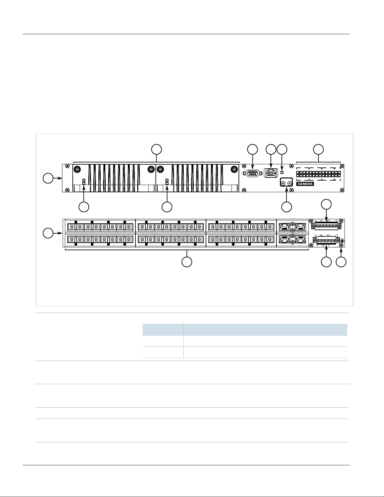
Figure1:RUGGEDCOM RSG2488
1.Front 2.Rear 3.Power Modules 4.Power Status LEDs 5.RS-232 Serial Console Port (DB9) 6.Management Port 7.Alarm
Indicator LED 8.Access Plate 9.Port Status LEDs 10.Line Modules 11.Power Supply Terminal Block 12.Chassis Ground Terminal
Power Status LEDs Indicates the status of the power modules.
LED Description
I The power module is receiving power
O The power module is supplying power
RS-232 Console Port The serial console port is for interfacing directly with the device and accessing initial
Management Port The 10/100Base-T Ethernet management port is for system management that is out-of-band
Alarm Indicator LED The alarm indicator LED illuminates when an alarm condition exists.
Access Plate The removable access plate provides access to the microSD slot. Use a microSD card to load/
Port Status LEDs Port status indicator LEDs indicate the operational status of each port.
management functions. For information about connecting to the device via the serial
console port, refer to Section2.9, “Connecting to the Device”.
from the switch fabric. For information about connecting to the device via the 10/100Base-T
Ethernet management port, refer to Section2.9, “Connecting to the Device”.
store the firmware and configuration for the device. For information about using a microSD
card, refer to Section2.8, “Inserting/Removing the MicroSD Card”.
2 Description
Page 13

RUGGEDCOM RSG2488
Installation Guide
Chapter 1
Introduction
State Description
Solid Link detected
Blinking Link activity
Off No link detected
Line Modules The device features slots for up to eight line modules. For more information, refer to
Chapter3, Modules.
Failsafe Alarm Relay Latches to default state when a power disruption or other alarm condition occurs. For more
information, refer to:
• Section2.5, “Connecting the Failsafe Alarm Relay”
• Section4.2, “Failsafe Alarm Relay Specifications”
Power Supply Terminal Block A pluggable terminal block. For more information, refer to:
• Section2.7, “Connecting Power”
• Section4.1, “Power Supply Specifications”
Chassis Ground Terminal Protects the device from power surges and accumulated static electricity. For information
about grounding the device, refer to Section2.6, “Grounding the Device”.
Description 3
Page 14

Chapter 1
Introduction
RUGGEDCOM RSG2488
Installation Guide
4 Description
Page 15
RUGGEDCOM RSG2488
Installation Guide
Installing the Device
This chapter describes how to install the device, including mounting the device, connecting power, and
connecting the device to the network.
DANGER!
Electrocution hazard – risk of serious personal injury and/or damage to equipment. Before performing
any maintenance tasks, make sure all power to the device has been disconnected and wait
approximately two minutes for any remaining energy to dissipate.
WARNING!
Radiation hazard – risk of serious personal injury. This product may contain a laser system and is
classified as a CLASS 1 LASER PRODUCT. Use of controls or adjustments or performance of procedures
other than those specified herein may result in hazardous radiation exposure.
Installing the Device
Chapter 2
IMPORTANT!
This product contains no user-serviceable parts. Attempted service by unauthorized personnel shall
render all warranties null and void.
Changes or modifications not expressly approved by Siemens Canada Ltd could invalidate
specifications, test results, and agency approvals, and void the user's authority to operate the
equipment.
IMPORTANT!
This product should be installed in a restricted access location where access can only be gained by
authorized personnel who have been informed of the restrictions and any precautions that must be
taken. Access must only be possible through the use of a tool, lock and key, or other means of security,
and controlled by the authority responsible for the location.
CONTENTS
• Section2.1, “General Procedure”
• Section2.2, “Required Tools and Materials”
• Section2.3, “Cabling Recommendations”
• Section2.4, “Mounting the Device”
• Section2.5, “Connecting the Failsafe Alarm Relay”
• Section2.6, “Grounding the Device”
• Section2.7, “Connecting Power”
• Section2.8, “Inserting/Removing the MicroSD Card”
• Section2.9, “Connecting to the Device”
• Section2.10, “Configuring the Device”
5
Page 16
Chapter 2
Installing the Device
Section2.1
RUGGEDCOM RSG2488
Installation Guide
General Procedure
The general procedure for installing the device is as follows:
1. Review the relevant certification information for any regulatory requirements. For more information, refer to
Section6.1, “Approvals”.
2. Review the RUGGEDCOM RSG2488 Modules Catalog for special installation or regulatory requirements related
to the modules installed in the device. In the case of Precision Time Protocol (PTP) line modules, this includes
antenna installation and regulatory requirements.
3. Mount the device.
4. Connect the failsafe alarm relay.
5. Connect power to the device and ground the device to safety Earth.
6. Connect the device to the network.
7. Configure the device.
Section2.2
Required Tools and Materials
The following tools and materials are required to install the RUGGEDCOM RSG2488:
Tools/Materials Purpose
AC/DC power cord (16 AWG) For connecting power to the device.
Lightning protector For protecting the device from harmful electrical strikes.
Shielded coaxial cables For connecting the device to antennas and an Ethernet network.
Flathead screwdriver For mounting the device to a DIN rail.
Phillips screwdriver For mounting the device to a panel.
4 x #6-32 screws For mounting the device to a panel.
Braided or equivalent ground wire For grounding the device to safety Earth.
Section2.3
Cabling Recommendations
Siemens recommends using SIMATIC NET industrial Ethernet shielded cables for all Ethernet ports.
CONTENTS
• Section2.3.1, “Protection On Twisted-Pair Data Ports”
• Section2.3.2, “Gigabit Ethernet 1000Base-TX Cabling Recommendations”
6 General Procedure
Page 17
RUGGEDCOM RSG2488
Installation Guide
Section2.3.1
Installing the Device
Protection On Twisted-Pair Data Ports
All copper Ethernet ports on RUGGEDCOM products include transient suppression circuitry to protect against
damage from electrical transients and conform with IEC 61850-3 and IEEE 1613 Class 1 standards. This means
that during a transient electrical event, communications errors or interruptions may occur, but recovery is
automatic.
Siemens also does not recommend using copper Ethernet ports to interface with devices in the field across
distances that could produce high levels of ground potential rise (i.e. greater than 2500 V), during line-to-ground
fault conditions.
Section2.3.2
Gigabit Ethernet 1000Base-TX Cabling Recommendations
The IEEE 802.3ab Gigabit Ethernet standard defines 1000 Mbit/s Ethernet communications over distances of up
to 100 m (328 ft) using all 4 pairs in category 5 (or higher) balanced, unshielded twisted-pair cabling. For wiring
guidelines, system designers and integrators should refer to the Telecommunications Industry Association (TIA)
TIA/EIA-568-A wiring standard that characterizes minimum cabling performance specifications required for proper
Gigabit Ethernet operation. For reliable, error-free data communication, new and pre-existing communication
paths should be verified for TIA/EIA-568-A compliance.
The following table summarizes the relevant cabling standards:
Chapter 2
Cabling Category
< 5 No New wiring infrastructure required.
5 Yes Verify TIA/EIA-568-A compliance.
5e Yes No action required. New installations should be designed with Category 5e or higher.
6 Yes No action required.
> 6 Yes Connector and wiring standards to be determined.
1000Base-
TX Compliant
Required Action
Follow these recommendations for copper data cabling in high electrical noise environments:
• Data cable lengths should be as short as possible, preferably 3 m (10 ft) in length. Copper data cables should
not be used for inter-building communications.
• Power and data cables should not be run in parallel for long distances, and should be installed in separate
conduits. Power and data cables should intersect at 90° angles when necessary to reduce inductive coupling.
• Shielded/screened cabling can be used when required. Care should be taken to avoid the creation of ground
loops with shielded cabling.
Section2.4
Mounting the Device
The RSG2488 is designed for maximum mounting and display flexibility. It can be ordered with adapters that allow
it to be installed in a 48 cm (19 in) rack, 35 mm (1.4 in) DIN rail, or directly on a panel.
Protection On Twisted-Pair Data Ports 7
Page 18

Chapter 2
33
21
Installing the Device
IMPORTANT!
Heat generated by the device is channeled outwards from the enclosure. As such, it is recommended
that 2.5 cm (1 in) of space be maintained on all open sides of the device to allow for some
convectional airflow.
Forced airflow is not required. However, any increase in airflow will result in a reduction of ambient
temperature and improve the long-term reliability of all equipment mounted in the rack space.
NOTE
For detailed dimensions of the device with either rack, DIN rail or panel hardware installed, refer to
Chapter5, Dimension Drawings.
CONTENTS
• Section2.4.1, “Mounting the Device to a Rack”
• Section2.4.2, “Mounting the Device on a DIN Rail”
• Section2.4.3, “Mounting the Device to a Panel”
RUGGEDCOM RSG2488
Installation Guide
Section2.4.1
Mounting the Device to a Rack
For rack mount installations, the RSG2488 can be ordered with rack mount adapters pre-installed at the front and
rear of the chassis. Additional adapters are provided to further secure the device in high-vibration or seismically
active locations.
To secure the device to a standard 48 cm (19 in) rack, do the following:
1. Make sure the front and rear rack mount adapters are installed on the both sides of the chassis.
NOTE
The chassis features multiple mounting holes, allowing the rack mount adapters to be installed up
to 25 mm (1 in) from the face of the device.
Figure2:Rack Mount Adapters
1.Rear 2.Front 3.Rack Mount Adapter
2. Insert the device into the rack. To make the modules and ports accessible from the front, insert the power
supply side of the device first. Reverse the orientation to have the power supplies, management ports and
LEDs accessible from the front.
3. Secure the adapters to the rack using the supplied hardware.
8 Mounting the Device to a Rack
Page 19

RUGGEDCOM RSG2488
3
1
1
2
2
Installation Guide
Section2.4.2
Installing the Device
Mounting the Device on a DIN Rail
For DIN rail installations, the RSG2488 can be ordered with panel/DIN rail adapters pre-installed on each side of
the chassis. The adapters allow the device to be slid onto a standard 35 mm (1.4 in) DIN rail.
To mount the device to a DIN rail, do the following:
1. Align the adapters with the DIN rails and slide the device into place.
Chapter 2
Figure3:DIN Rail Mounting
1.DIN Rail 2.Panel/DIN Rail Adapter 3.Screw
2. Install one of the supplied screws on either side of the device to secure the adapters to the DIN rails.
Section2.4.3
Mounting the Device to a Panel
For panel installations, the RSG2488 can be ordered with panel/DIN rail adapters pre-installed on each side of the
chassis. The adapters allow the device to be attached to a panel using screws.
To mount the device to a panel, do the following:
1. Place the device against the panel and align the adapters with the mounting holes.
Mounting the Device on a DIN Rail 9
Page 20

Chapter 2
2
1
1
Installing the Device
RUGGEDCOM RSG2488
Installation Guide
Figure4:Panel Mounting
1.Screw 2.Panel/DIN Rail Adapter
2. Install the supplied screws to secure the adapters to the panel.
Section2.5
Connecting the Failsafe Alarm Relay
The failsafe relay can be configured to latch based on alarm conditions. The NO (Normally Open) contact is closed
when the unit is powered and there are no active alarms. If the device is not powered or if an active alarm is
configured, the relay opens the NO contact and closes the NC (Normally Closed) contact.
NOTE
Control of the failsafe relay output is configurable through ROS. One common application for this relay
is to signal an alarm if a power failure occurs. For more information, refer to the ROS User Guide for
the RSG2488.
The following shows the proper relay connections.
10 Connecting the Failsafe Alarm Relay
Page 21

RUGGEDCOM RSG2488
3
5
4
3
5
4
2
1
3
1
2
Installation Guide
Figure5:Failsafe Alarm Relay Wiring
1.Pluggable Terminal Block for HI Power Supplies 2.Screw-Type Terminal Block for HIP Power Supplies 3.Normally Open Terminal
4.Common Terminal 5.Normally Closed Terminal
Section2.6
Installing the Device
Grounding the Device
The RSG2488 chassis ground terminal uses an M3 screw. It is recommended to terminate the ground connection
with an M3 ring or spade lug and torque it to 1.7 N·m (15 lbf-in).
Chapter 2
Figure6:Chassis Ground Connection
1.M3 Screw 2.Standoff 3.M3 Ring Lug
Section2.7
Connecting Power
The RUGGEDCOM RSG2488 supports dual redundant AC and/or DC power supplies that can be installed in any
combination. The use of two power modules is recommended to provide redundancy and load balancing.
The RUGGEDCOM RSG2488 can be equipped with either a screw-type or pluggable terminal block, which provides
power to both power supplies. The screw-type terminal block is installed using Phillips screws and compression
plates, allowing either bare wire connections or crimped terminal lugs. Use #6 size ring lugs for secure, reliable
connections under severe shock or vibration.
Grounding the Device 11
Page 22

Chapter 2
Installing the Device
DANGER!
Electrocution hazard – risk of serious personal injury or death. The device may have two power
supplies equipped, which may be connected to separate power sources. Make sure all power sources
are off before servicing the power supply terminals.
CAUTION!
Electrical hazard – risk of damage to equipment. Do not connect wiring to unused power supply input
terminals. For instance, if a Low DC power supply is installed in the PS1 slot, do not connect the PS1
High AC/DC terminals to a power source.
IMPORTANT!
• In a high AC/DC and low DC (24/48 V) power supply arrangement, the placement of the AC and
• Use only #16 gage wiring when connecting terminal blocks.
• The maximum wire length between the terminal block and power source must not exceed 6 m (20 ft)
• A circuit breaker rated no higher than 20 A must be installed between the device and the supply
• Whenever possible, use a separate circuit breaker for each power supply.
• For maximum redundancy in a dual power supply configuration, use two independent power
• A socket outlet/disconnect device must be installed near the device and be easily accessible.
• Equipment must be installed according to applicable local wiring codes and standards.
RUGGEDCOM RSG2488
Installation Guide
DC power supplies is not slot-dependent. However, if a high AC/DC power supply is installed in slot
PS1, the high AC/DC wiring must be connected to the high terminal block PS1 terminals. If a low DC
power supply is installed in slot PS1, the low DC wiring must be made to the low terminal block PS1
terminals. High voltage wiring is always made to the upper Hi terminal block and low voltage (24/48
V) wiring is always made to the lower Lo terminal block.
for 24 V power supplies or 18 m (60 ft) for 48 V power supplies.
mains.
sources.
CONTENTS
• Section2.7.1, “Connecting High AC/DC Power”
• Section2.7.2, “Connecting Low DC Power”
• Section2.7.3, “Wiring Examples”
Section2.7.1
Connecting High AC/DC Power
To connect a high AC/DC power supply to the device, do the following:
DANGER!
Electrocution hazard – risk of death, serious personal injury and/or damage to the device. Make sure
the supplied cover is always installed over high voltage screw-type terminal blocks.
12 Connecting High AC/DC Power
Page 23

RUGGEDCOM RSG2488
1
2
4
6
3
5
3
5
4
6
Installation Guide
Installing the Device
CAUTION!
Electrical hazard – risk of damage to equipment. Do not connect AC power cables to a DC power supply
terminal block. Damage to the power supply may occur.
NOTE
The screw-type terminal block is installed using Phillips screws and compression plates, allowing either
bare wire connections or crimped terminal lugs. Use #6 size ring lugs for secure, reliable screws, which
must be removed to make connections.
1. Connect the positive wire from the power source to the positive/live (+/L) terminal on the terminal block.
Chapter 2
Figure7:AC Terminal Block Wiring
1.Screw-Type Terminal Block for HIP Power Supplies 2.Pluggable Terminal Block for HI Power Supplies 3.Positive/Live (+/L)
Terminal for PS1 4.Neutral/Negative (-/N) Terminal for PS1 5.Positive/Live (+/L) Terminal for PS2 6.Neutral/Negative (-/N)
Terminal for PS2
2. Connect the negative wire from the power source to the neutral/negative (-/N) terminal on the terminal block.
3. Connect the ground terminal on the power source to the ground terminal on the device. For more
information, refer to Section2.6, “Grounding the Device”.
Section2.7.2
Connecting Low DC Power
To connect a low DC power supply to the device, do the following:
NOTE
The screw-type terminal block is installed using Phillips screws and compression plates, allowing either
bare wire connections or crimped terminal lugs. Use #6 size ring lugs for secure, reliable screws, which
must be removed to make connections.
1. Connect the positive wire from the power source to the positive terminal on the terminal block.
Connecting Low DC Power 13
Page 24

Chapter 2
2
4
1
6
3
5
4
5
6
3
7
7
7
7
Installing the Device
Figure8:DC Terminal Block Wiring
1.Screw-Type Terminal Block for 24 and 48 Power Supply 2.Pluggable Terminal Block for 24P and 48P Power Supply 3.Positive
Terminal for PS1 4.Negative Terminal for PS1 5.Positive Terminal for PS2 6.Negative Terminal for PS2 7.Chassis Ground
2. Connect the negative wire from the power source to the negative terminal on the terminal block.
3. Connect the ground terminal on the power source to the ground terminal on the device. For more
information, refer to Section2.6, “Grounding the Device”.
RUGGEDCOM RSG2488
Installation Guide
Section2.7.3
Wiring Examples
The following illustrate how to connect power to single and dual power supplies.
Figure9:Single High AC/DC Power Supply
14 Wiring Examples
Page 25

RUGGEDCOM RSG2488
+
+
Installation Guide
Figure10:Single Low DC Power Supply
Installing the Device
Chapter 2
Figure11:Dual High AC/DC Power Supply
Wiring Examples 15
Page 26

Chapter 2
+
+
+
+
Installing the Device
Figure12:Dual Low DC Power Supply
RUGGEDCOM RSG2488
Installation Guide
Figure13:High AC/DC Power Supply and Low DC Power Supply
Section2.8
Inserting/Removing the MicroSD Card
The RUGGEDCOM RSG2488 accepts a microSD card for storing configuration files and/or software updates.
16 Inserting/Removing the MicroSD Card
Page 27

RUGGEDCOM RSG2488
2
1
Installation Guide
CAUTION!
Configuration hazard – risk of data loss. The microSD card must not be removed or replaced during
normal operation of the device. Make sure the device is powered down before removing or inserting
the card.
CAUTION!
Mechanical/electrical hazard – risk of damage to the microSD card.
• Do not expose the microSD card to extreme temperatures or humidity
• Do not expose the microSD card to large magnetic or static electric fields
• Do not bend or drop the microSD card
CAUTION!
Security hazard – risk of unauthorized access and/or exploitation. Make sure to remove the microSD
card before decommissioning the device or sending the device to a third-party.
To insert or remove a microSD card, do the following:
1. Power down the device.
2. Unscrew the retention screws and remove the access plate.
Installing the Device
Chapter 2
Figure14:Inserting/Removing a MicroSD Card
1.Access Plate 2.MicroSD Card
3. Without touching the contacts on the card, insert or remove the microSD card.
4. Install the access plate and finger-tighten the retention screws.
5. Power up the device.
Section2.9
Connecting to the Device
The following describes the various methods for accessing the ROS console and Web interfaces on the device. For
more detailed instructions, refer to the RUGGEDCOM ROS User Guide for the RUGGEDCOM RSG2488.
Serial Console and Management Ports
Connect a workstation directly to the serial console or management ports to access the boot-time control and ROS
interfaces. The serial console port provides access to ROS's console interface, while the management port provides
access to ROS's console and Web interfaces.
Connecting to the Device 17
Page 28

Chapter 2
5
9 6
1
8
1
Installing the Device
IMPORTANT!
The serial console and management (MGMT) ports are intended to be used only as temporary
connections during initial configuration or troubleshooting.
The serial console port implements RS-232 DCE (Data Communication Equipment) on a DB9 connector. The
following is the pin-out for the port:
Pin Name Description
1 DCD Data Carrier Detect
2 RX Receive Data
3 TX Transmit Data
4 DTR Data Terminal Ready
5 GND Signal Ground
6 DSR Data Set Ready
RUGGEDCOM RSG2488
Installation Guide
Figure15:Serial DB9 Console Port
7 RTS Request to Send
8 CTS Clear To Send
9 Reserved (Do Not Connect)
The management port is a 10/100Base-TX copper Ethernet port with an RJ45 connector. The following is the pinout for the management port:
Pin Name Description
1 TX+ Transmit Data+
2 TX- Transmit Data-
3 RX+ Receive Data+
Figure16:RJ45 Management Port
4 Reserved (Do Not Connect)
5 Reserved (Do Not Connect)
6 RX- Receive Data-
7 Reserved (Do Not Connect)
8 Reserved (Do Not Connect)
Communication Ports
Connect any of the available Ethernet ports on the device to a management switch and access the ROS console
and Web interfaces via the device's IP address. The factory default IP address for the RUGGEDCOM RSG2488 is
https://192.168.0.2.
For more information about available ports, refer to Chapter3, Modules.
18 Connecting to the Device
Page 29

RUGGEDCOM RSG2488
Installation Guide
Section2.10
Installing the Device
Configuring the Device
Once the device is installed and connected to the network, it must be configured. All configuration management
is done via the RUGGEDCOM ROS interface. For more information about configuring the device, refer to the
RUGGEDCOM ROS User Guide associated with the installed software release.
Chapter 2
Configuring the Device 19
Page 30

Chapter 2
Installing the Device
RUGGEDCOM RSG2488
Installation Guide
20 Configuring the Device
Page 31

RUGGEDCOM RSG2488
3
4
1 2
5
7
6
8
9
10
Installation Guide
Modules
The RUGGEDCOM RSG2488 features slots for up to eight field-replaceable line modules, which can be used to
expand and customize the capabilities of the device to suit specific applications. A variety of modules are available,
each featuring a specific type of communication port: copper Ethernet, fiber optic Ethernet and Small Form-factor
Pluggable (SFP). A Precision Time Protocol (PTP) module for accurate clock synchronization is also available.
Modules can be installed in any one of the available slots in the device chassis.
Use the ROS software to determine which ports are equipped on the device. For more information, refer to the
ROS User Guide for the device.
Chapter 3
Modules
Figure17:Available Chassis Slots
1.Power Module Slot (PS1) 2.Power Module Slot (PS2) 3.Line Module Slot (Slot 1) 4.Line Module Slot (Slot 2) 5.Line Module Slot
(Slot 3) 6.Line Module Slot (Slot 4) 7.Line Module Slot (Slot 5) 8.Line Module Slot (Slot 6) 9.Line Module Slot (Slot 7) 10.Line
Module Slot (Slot 8)
NOTE
The PTP module can only be installed in slot 1.
Slot Module Type
PS1 and PS2 Power Supply Module
1 4-Port Copper Ethernet, Fiber Optic Ethernet, SFP Transceiver or PTP Module
2 to 6 4-Port Copper Ethernet, Fiber Optic Ethernet or SFP Transceiver
21
Page 32

Chapter 3
Modules
Slot Module Type
7 to 8 2-Port Copper Ethernet, Fiber Optic Ethernet or SFP Transceiver
CONTENTS
• Section3.1, “Available Modules”
• Section3.2, “Installing/Removing Line Modules”
• Section3.3, “Installing/Removing Power Modules”
Section3.1
Available Modules
The following modules are available for use with the RUGGEDCOM RSG2488. For more information
about individual modules, refer to the RUGGEDCOM RSG2488 Series Modules Catalog [https://
support.industry.siemens.com/cs/ca/en/view/109757282].
RUGGEDCOM RSG2488
Installation Guide
Power Supply Modules
RUGGEDCOM RPM2410 Specifications
Input Range: 13 to 36 VDC
RUGGEDCOM RPM2420 Specifications
Input Range: 36 to 72 VDC
RUGGEDCOM RPM2430 Specifications
Input Range: 88 to 300 VDC or
85 to 264 VAC
Article Numbers
6GK6000-8PS11-1EA0
(Standard)
6GK6000-8PS11-1EA1
(Conformal Coated)
Article Numbers
6GK6000-8PS12-1EA0
(Standard)
6GK6000-8PS12-1EA1
(Conformal Coated)
Article Numbers
6GK6000-8PS13-1EA0
(Standard)
6GK6000-8PS13-1EA1
(Conformal Coated)
22 Available Modules
Page 33

RUGGEDCOM RSG2488
Installation Guide
Copper Ethernet Modules
Chapter 3
Modules
RUGGEDCOM RMM2473-2FC Specifications
Ports: 2
Port Type: FastConnect RJ45
Speed: 1000 Mbps
Interface: TX
Distance: 100 m (328 ft)
RUGGEDCOM RMM2473-2RJ45 Specifications
Ports: 2
Port Type: RJ45
Speed: 1000 Mbps
Interface: TX
Distance: 100 m (328 ft)
RUGGEDCOM RMM2473-2M12A Specifications
Ports: 2
Port Type: M12 (8-Pin, A-Coded)
Speed: 1000 Mbps
Interface: TX
Distance: 100 m (328 ft)
RUGGEDCOM RMM2473-2M12X Specifications
Ports: 2
Port Type: M12 (8-Pin, X-Coded)
Speed: 1000 Mbps
Interface: TX
Distance: 100 m (328 ft)
Article Numbers
6GK6000-8CG02-2EA0
(Standard)
6GK6000-8CG02-2EA1
(Conformal Coated)
Article Numbers
6GK6000-8CG01-2EA0
(Standard)
6GK6000-8CG01-2EA1
(Conformal Coated)
Article Numbers
6GK6000-8CG03-2EA0
(Standard)
6GK6000-8CG03-2EA1
(Conformal Coated)
Article Numbers
6GK6000-8CG04-2EA0
(Standard)
6GK6000-8CG04-2EA1
(Conformal Coated)
RUGGEDCOM RMM2473-4FC Specifications
Ports: 4
Port Type: FastConnect RJ45
Speed: 1000 Mbps
Interface: TX
Distance: 100 m (328 ft)
RUGGEDCOM RMM2473-4RJ45 Specifications
Ports: 4
Port Type: RJ45
Speed: 1000 Mbps
Interface: TX
Distance: 100 m (328 ft)
RUGGEDCOM RMM2473-4M12A Specifications
Ports: 4
Port Type: M12 (8-Pin, A-Coded)
Speed: 1000 Mbps
Interface: TX
Distance: 100 m (328 ft)
Article Numbers
6GK6000-8CG02-4EA0
(Standard)
6GK6000-8CG02-4EA1
(Conformal Coated)
Article Numbers
6GK6000-8CG01-4EA0
(Standard)
6GK6000-8CG01-4EA1
(Conformal Coated)
Article Numbers
6GK6000-8CG03-4EA0
(Standard)
6GK6000-8CG03-4EA1
(Conformal Coated)
Available Modules 23
Page 34

Chapter 3
Modules
RUGGEDCOM RSG2488
Installation Guide
RUGGEDCOM RMM2473-4M12X Specifications
Ports: 4
Port Type: M12 (8-Pin, X-Coded)
Speed: 1000 Mbps
Interface: TX
Distance: 100 m (328 ft)
Fiber Optic Ethernet Modules
RUGGEDCOM RMM2464-4ST2 Specifications
Ports: 4
Port Type: ST
Mode: MM (Multi-Mode)
Speed: 100 Mbps
Interface: FX
Wavelength: 1310 nm
Distance: 2 km (1.2 mi)
RUGGEDCOM RMM2465-4ST20 Specifications
Ports: 4
Port Type: ST
Mode: SM (Single-Mode)
Speed: 100 Mbps
Interface: FX
Wavelength: 1310 nm
Distance: 20 km (12.4 mi)
Article Numbers
6GK6000-8CG04-4EA0
(Standard)
6GK6000-8CG04-4EA1
(Conformal Coated)
Article Numbers
6GK6000-8FX01-4EA0
(Standard)
6GK6000-8FX01-4EA1
(Conformal Coated)
Article Numbers
6GK6000-8FX04-4EA0
(Standard)
6GK6000-8FX04-4EA1
(Conformal Coated)
RUGGEDCOM RMM2464-4LC2 Specifications
Ports: 4
Port Type: LC
Mode: MM (Multi-Mode)
Speed: 100 Mbps
Interface: FX
Wavelength: 1310 nm
Distance: 2 km (1.2 mi)
RUGGEDCOM RMM2475-4LC10 Specifications
Ports: 4
Port Type: LC
Mode: SM (Single-Mode)
Speed: 100 Mbps
Interface: LX
Wavelength: 1310 nm
Distance: 10 km (12.4 mi)
Article Numbers
6GK6000-8FX11-4EA0
(Standard)
6GK6000-8FX11-4EA1
(Conformal Coated)
Article Numbers
6GK6000-8FG03-4EA0
(Standard)
6GK6000-8FG03-4EA1
(Conformal Coated)
24 Available Modules
Page 35

RUGGEDCOM RSG2488
Installation Guide
Chapter 3
Modules
RUGGEDCOM RMM2465-4LC20 Specifications
Ports: 4
Port Type: LC
Mode: SM (Single-Mode)
Speed: 100 Mbps
Interface: FX
Wavelength: 1310 nm
Distance: 20 km (12.4 mi)
RUGGEDCOM RMM2475-4LC25 Specifications
Ports: 4
Port Type: LC
Mode: SM (Single-Mode)
Speed: 1000 Mbps
Interface: LX
Wavelength: 1310 nm
Distance: 25 km (15.5 mi)
RUGGEDCOM RMM2465-4LC50 Specifications
Ports: 4
Port Type: LC
Mode: SM (Single-Mode)
Speed: 100 Mbps
Interface: FX
Wavelength: 1310 nm
Distance: 50 km (31.1 mi)
Article Numbers
6GK6000-8FX06-4EA0
(Standard)
6GK6000-8FX06-4EA1
(Conformal Coated)
Article Numbers
6GK6000-8FG05-4EA0
(Standard)
6GK6000-8FG05-4EA1
(Conformal Coated)
Article Numbers
6GK6000-8FX08-4EA0
(Standard)
6GK6000-8FX08-4EA1
(Conformal Coated)
RUGGEDCOM RMM2465-4LC90 Specifications
Ports: 4
Port Type: LC
Mode: SM (Single-Mode)
Speed: 100 Mbps
Interface: FX
Wavelength: 1310 nm
Distance: 90 km (55.9 mi)
RUGGEDCOM RMM2464-4SC2 Specifications
Ports: 4
Port Type: SC
Mode: MM (Multi-Mode)
Speed: 100 Mbps
Interface: FX
Wavelength: 1300 nm
Distance: 2 km (1.2 mi)
RUGGEDCOM RMM2475-4SC10 Specifications
Ports: 4
Port Type: SC
Mode: SM (Single-Mode)
Speed: 1000 Mbps
Article Numbers
6GK6000-8FX10-4EA0
(Standard)
6GK6000-8FX10-4EA1
(Conformal Coated)
Article Numbers
6GK6000-8FX02-4EA0
(Standard)
6GK6000-8FX02-4EA1
(Conformal Coated)
Article Numbers
6GK6000-8FG02-4EA0
(Standard)
6GK6000-8FG02-4EA1
(Conformal Coated)
Available Modules 25
Page 36

Chapter 3
Modules
RUGGEDCOM RSG2488
Installation Guide
Interface: LX
Wavelength: 1310 nm
Distance: 10 km (6.2 mi)
RUGGEDCOM RMM2465-4SC20 Specifications
Ports: 4
Port Type: SC
Mode: SM (Single-Mode)
Speed: 100 Mbps
Interface: FX
Wavelength: 1310 nm
Distance: 20 km (12.4 mi)
RUGGEDCOM RMM2475-4SC50 Specifications
Ports: 4
Port Type: SC
Mode: SM (Single-Mode)
Speed: 1000 Mbps
Interface: FX
Wavelength: 1310 nm
Distance: 50 km (31.1 mi)
RUGGEDCOM RMM2465-4SC90 Specifications
Ports: 4
Port Type: SC
Mode: SM (Single-Mode)
Speed: 100 Mbps
Interface: FX
Wavelength: 1310 nm
Distance: 90 km (55.9 mi)
Article Numbers
6GK6000-8FX05-4EA0
(Standard)
6GK6000-8FX05-4EA1
(Conformal Coated)
Article Numbers
6GK6000-8FG04-4EA0
(Standard)
6GK6000-8FG04-4EA1
(Conformal Coated)
Article Numbers
6GK6000-8FX03-4EA0
(Standard)
6GK6000-8FX03-4EA1
(Conformal Coated)
RUGGEDCOM RMM2472-2SFP Specifications
Sockets: 2
SFP Included: No
a
Article Numbers
6GK6000-8FG50-2EA0
(Standard)
6GK6000-8FG50-2EA1
(Conformal Coated)
RUGGEDCOM RMM2474-2SFP Specifications
Ports: 2
Speed: 1000 Mbps
Interface: SX
Article Numbers
6GK6000-8FG51-2EA0
(Standard)
6GK6000-8FG51-2EA1
(Conformal Coated)
SFP Included: RUGGEDCOM
SFP1122-1SX
RUGGEDCOM RMM2464-2SFP2 Specifications
Ports: 2
Speed: 100 Mbps
Interface: FX
Article Numbers
6GK6000-8FX51-2EA0
(Standard)
6GK6000-8FX51-2EA1
(Conformal Coated)
SFP Included: RUGGEDCOM
SFP1121-1FX2
26 Available Modules
Page 37

RUGGEDCOM RSG2488
Installation Guide
Chapter 3
Modules
RUGGEDCOM RMM2475-2SFP10 Specifications
Ports: 2
Speed: 1000 Mbps
Interface: LX
SFP Included: RUGGEDCOM
SFP1132-1LX10
RUGGEDCOM RMM2475-2SFP25 Specifications
Ports: 2
Speed: 1000 Mbps
Interface: LX
SFP Included: RUGGEDCOM
SFP1132-1LX25
RUGGEDCOM RMM2475-2SFP70 Specifications
Ports: 2
Speed: 1000 Mbps
Interface: LX
SFP Included: RUGGEDCOM
SFP1132-1LX70
RUGGEDCOM RMM2472-4SFP Specifications
Sockets: 4
SFP Included: No
Article Numbers
6GK6000-8FG52-2EA0
(Standard)
6GK6000-8FG52-2EA1
(Conformal Coated)
Article Numbers
6GK6000-8FG53-2EA0
(Standard)
6GK6000-8FG53-2EA1
(Conformal Coated)
Article Numbers
6GK6000-8FG54-2EA0
(Standard)
6GK6000-8FG54-2EA1
(Conformal Coated)
Article Numbers
6GK6000-8FG50-4EA0
a
(Standard)
6GK6000-8FG50-4EA1
(Conformal Coated)
RUGGEDCOM RMM2474-4SFP Specifications
Ports: 4
Speed: 1000 Mbps
Interface: SX
SFP Included: RUGGEDCOM
SFP1122-1SX
RUGGEDCOM RMM2475-4SFP10 Specifications
Ports: 4
Speed: 1000 Mbps
Interface: LX
SFP Included: RUGGEDCOM
SFP1132-1LX10
RUGGEDCOM RMM2475-4SFP25 Specifications
Ports: 4
Speed: 1000 Mbps
Interface: LX
SFP Included: RUGGEDCOM
SFP1132-1LX25
RUGGEDCOM RMM2475-4SFP70 Specifications
Ports: 4
Speed: 1000 Mbps
Interface: LX
Article Numbers
6GK6000-8FG51-4EA0
(Standard)
6GK6000-8FG51-4EA1
(Conformal Coated)
Article Numbers
6GK6000-8FG52-4EA0
(Standard)
6GK6000-8FG52-4EA1
(Conformal Coated)
Article Numbers
6GK6000-8FG53-4EA0
(Standard)
6GK6000-8FG53-4EA1
(Conformal Coated)
Article Numbers
6GK6000-8FG54-4EA0
(Standard)
6GK6000-8FG54-4EA1
(Conformal Coated)
Available Modules 27
Page 38

Chapter 3
Modules
a
Refer to details for a list of compatible SFPs.
Precision Time Protocol (PTP) Modules
RUGGEDCOM RSG2488
Installation Guide
SFP Included: RUGGEDCOM
SFP1132-1LX70
RUGGEDCOM RMM2431-5PTP Specifications
Ports: 5
Protocols: PTP and NTP
Synchronization Sources: NTP,
IEEE 1588 v2, IRIG-B PWM, GPS
Port Type: BNC
Blank Modules
RUGGEDCOM RMM2431-2 Specifications
—
RUGGEDCOM RMM2431-4 Specifications
—
Article Numbers
6GK6000-8PT01-4EA0
(Standard)
6GK6000-8PT01-4EA1
(Conformal Coated)
Article Numbers
6GK6000-8AA00-2EA0
(Standard)
6GK6000-8AA00-2EA1
(Conformal Coated)
Article Numbers
6GK6000-8AA00-4EA0
(Standard)
6GK6000-8AA00-4EA1
(Conformal Coated)
Section3.2
Installing/Removing Line Modules
Upon installing a new line module in the device, all features associated with the module are available in
RUGGEDCOM ROS. For more information, refer to the RUGGEDCOM ROS User Guide for the RUGGEDCOM
RSG2488.
Once a line module is removed, all the features associated with the module are hidden or disabled in RUGGEDCOM
ROS.
IMPORTANT!
Only one Precision Time Protocol (PTP) line module is supported per chassis.
CAUTION!
Contamination hazard – risk of equipment damage. Prevent the ingress of water, dirts and other debris
that may lead to premature equipment failure. Always make sure slots are not left empty and open
ports are protected with plugs or covers.
28 Installing/Removing Line Modules
Page 39

RUGGEDCOM RSG2488
3
1
2
Installation Guide
Removing a Module
To remove a line module, do the following:
1. Make sure power to the device has been disconnected and wait approximately two minutes for any remaining
energy to dissipate.
2. [Optional] If the device is installed in a rack, remove it from the rack.
3. Loosen the screws that secure the module.
4. Pull the module from the chassis to disconnect it.
Chapter 3
Modules
Figure18:Removing a Module
1.Module 2.Chassis 3.Screw
5. Install a new module or a blank module (to prevent the ingress of dust and dirt).
6. [Optional] If necessary, install the device in the rack.
7. Connect power to the device.
Installing a Module
To install a line module, do the following:
1. Make sure power to the device has been disconnected and wait approximately two minutes for any remaining
energy to dissipate.
2. [Optional] If the device is installed in a rack, remove it from the rack.
3. Remove the current module from the slot.
4. Insert the new module into the slot.
Installing/Removing Line Modules 29
Page 40

Chapter 3
3
1
2
Modules
RUGGEDCOM RSG2488
Installation Guide
Figure19:Installing a Module
1.Module 2.Chassis 3.Screw
5. Tighten the screws to secure the module.
6. [Optional] If necessary, install the device in the rack.
7. Connect power to the device.
Section3.3
Installing/Removing Power Modules
The RUGGEDCOM RSG2488 supports dual redundant power supply modules.
CAUTION!
Contamination hazard – risk of equipment damage. Prevent the ingress of water, dirts and other debris
that may lead to premature equipment failure. Always make sure slots are not left empty.
NOTE
Power modules are hot swappable. When installing/removing a power module, it is not necessary to
turn off power to the redundant power module.
Removing a Power Module
To remove a power module, do the following:
1. Loosen the screws that secure the module to the chassis until the module can be removed.
2. Slide the module out of the chassis.
30 Installing/Removing Power Modules
Page 41

RUGGEDCOM RSG2488
2
3
1
2
3
1
Installation Guide
Figure20:Removing a Power Supply
1.Screws 2.Power Supply 3.Chassis
3. Turn off power to the module.
4. Disconnect the power supply wiring from the terminal block. Alternatively, for convenience, remove the
terminal block with the wiring still connected and set it aside to be connected later to the new module.
5. Install a new or blank module to prevent the ingress of dust and dirt.
Chapter 3
Modules
Installing a Power Module
To install a power module, do the following:
1. If equipped, remove the existing module.
2. If applicable, connect the supplied terminal block to the module or connect the terminal block from the
previous module.
3. Confirm or connect the wiring from the power supply to the module. For more information, refer to
Section2.7, “Connecting Power”.
4. Insert the module into the empty slot.
Figure21:Installing a Power Module
1.Screws 2.Power Supply 3.Chassis
5. Hand-tighten the screws to secure the power module to the chassis.
Installing/Removing Power Modules 31
Page 42

Chapter 3
Modules
RUGGEDCOM RSG2488
Installation Guide
6. Turn on power to the module and confirm the module is receiving and supplying power. This is indicated by
the LEDs on the module.
LED State Description
O Green The module is supplying power
I Green The module is receiving power
32 Installing/Removing Power Modules
Page 43

RUGGEDCOM RSG2488
Installation Guide
Technical Specifications
This section provides important technical specifications related to the device.
CONTENTS
• Section4.1, “Power Supply Specifications”
• Section4.2, “Failsafe Alarm Relay Specifications”
• Section4.3, “Supported Networking Standards”
• Section4.4, “Operating Environment”
• Section4.5, “Mechanical Specifications”
Technical Specifications
Chapter 4
Section4.1
Power Supply Specifications
NOTE
Use the internal fuse rating to determine the size of the external circuit breaker/fuse.
Power
Supply Type
24 VDC (Single) 13 VDC 36 VDC 10 A 62 W 9.4 m (30.8 ft)
48 VDC (Single)
High Voltage
AC/DC
a
Based on #16 AWG wiring.
Section4.2
Terminal
Block Type
Screw
Screw/Pluggable
Input Range
Min Max
38 VDC 72 VDC 5 A 59 W 44.9 m (167 ft)
98 VDC 300 VDC
88 VAC 264 VAC
Internal
Fuse Rating
3.15 A 66 W —
Maximum Power
Consumption
Failsafe Alarm Relay Specifications
Maximum
Cable Length
a
IMPORTANT!
The alarm switching voltage must be greater than the Safety Extra Low-Voltage (SELV) to meet safety
requirements.
Parameter Value (Resistive Load)
Maximum Switching Voltage 250 VAC
Power Supply Specifications 33
Page 44

Chapter 4
Technical Specifications
RUGGEDCOM RSG2488
Installation Guide
Parameter Value (Resistive Load)
30 VDC
Rated Switching Current
Maximum Switching Capacity
Section4.3
Supported Networking Standards
Parameter 10 Mbps 100 Mbps 1000 Mbps Notes
IEEE 802.1AB Yes Yes Yes Link Layer Discovery Protocol (LLDP)
IEEE 802.1D Yes Yes Yes MAC bridges
IEEE 802.1Q Yes Yes Yes VLAN (Virtual LAN)
IEEE 802.1p Yes Yes Yes Priority levels
IEEE 802.1x Yes Yes Yes Port-based network access control
IEEE 802.3 Yes No No 10Base-T
IEEE 802.3u No Yes No 100Base-TX/100Base-FX
IEEE 802.3z No No Yes 1000Base-SX/LX
2 A @ 250 VAC
2 A @ 30 VDC
150 W
500 VA
IEEE 802.3ab No No Yes 1000Base-TX
IEEE 802.3x Yes Yes Yes Full duplex operation
Section4.4
Operating Environment
Parameter Range Comments
Ambient Operating Temperature -40 to 85 °C
(-40 to 185 °F)
Ambient Relative Humidity 5% to 95% Non-condensing
Ambient Storage Temperature -40 to 85 °C
(-40 to 185 °F)
Section4.5
Mechanical Specifications
Dimensions Refer to Chapter5, Dimension Drawings
Measured from a 30 cm (11.8 in) radius surrounding the center of
the enclosure
34 Supported Networking Standards
Page 45

RUGGEDCOM RSG2488
Installation Guide
Weight 8.6 kg (19 lbs)
Enclosure Aluminum
Technical Specifications
Chapter 4
Mechanical Specifications 35
Page 46

Chapter 4
Technical Specifications
RUGGEDCOM RSG2488
Installation Guide
36 Mechanical Specifications
Page 47

RUGGEDCOM RSG2488
376.0
442.4
44.0
Installation Guide
Dimension Drawings
Dimension Drawings
Chapter 5
NOTE
All dimensions are in millimeters, unless otherwise stated.
Figure22:Overall Dimensions
37
Page 48

Chapter 5
24.4
369.8
350.2
43.9
31.8
4.7
6.4
483.5
465.2
51.1
248.4
299.5
21.1
44
Dimension Drawings
RUGGEDCOM RSG2488
Installation Guide
Figure23:Rack Mount Dimensions
38
Page 49

RUGGEDCOM RSG2488
490.6
134.5
277.4
98.6
25.4
51.6
7.6
148.3
227.7
480.5
160.0
1
110.0
91.4
21.8
104.1
Installation Guide
Dimension Drawings
Chapter 5
Figure24:Panel and Din Rail Mount Dimensions
1.DIN Rail Centerline
Figure25:4-Port Line Module Dimensions
39
Page 50

Chapter 5
49.8
21.8
91.4
95.0
43.9 129.8
196.6
Dimension Drawings
Figure26:2-Port Line Module Dimensions
RUGGEDCOM RSG2488
Installation Guide
Figure27:Power Module Dimensions
40
Page 51

RUGGEDCOM RSG2488
Installation Guide
Certification
The RUGGEDCOM RSG2488 device has been thoroughly tested to guarantee its conformance with recognized
standards and has received approval from recognized regulatory agencies.
NOTE
Certifications related to individual modules are detailed in the RUGGEDCOM Modules Catalog for the
device available online.
CONTENTS
• Section6.1, “Approvals”
• Section6.2, “EMC and Environmental Type Tests”
Chapter 6
Certification
Section6.1
Approvals
The following details the approvals issued for the RUGGEDCOM RSG2488.
CONTENTS
• Section6.1.1, “TÜV SÜD”
• Section6.1.2, “European Union (EU)”
• Section6.1.3, “FCC”
• Section6.1.4, “ISED”
• Section6.1.5, “ACMA”
• Section6.1.6, “RoHS”
• Section6.1.7, “Other Approvals”
Section6.1.1
TÜV SÜD
This device is certified by TÜV SÜD to meet the requirements of the following standards:
• CSA/EN/IEC/UL 60950-1
Information Technology Equipment – Safety – Part 1: General Requirements)
Approvals 41
Page 52

Chapter 6
Certification
Section6.1.2
RUGGEDCOM RSG2488
Installation Guide
European Union (EU)
This device is declared by Siemens Canada Ltd to comply with essential requirements and other relevant provisions
of the following EU directives:
• EN 60950-1
Information Technology Equipment – Safety – Part 1: General Requirements
• EN 61000-6-2
Electromagnetic Compatibility (EMC) – Part 6-2: Generic Standards – Immunity for Industrial Environments
• EN 60825-1
Safety of Laser Products – Equipment Classification and Requirements
• EN 55022
Information Technology Equipment – Radio disturbance characteristics – Limits and methods of measurement
• EN 50581
Technical Documentation for the Assessment of Electrical and Electronic Products with Respect to the Restriction
of Hazardous Substances
The device is marked with a CE marking and can be used throughout the European community.
A copy of the CE Declaration of Conformity is available from Siemens Canada Ltd. For contact information, refer to
“Contacting Siemens”.
Section6.1.3
FCC
This device has been tested and found to comply with the limits for a Class A digital device, pursuant to Part 15 of
the FCC Rules. These limits are designed to provide reasonable protection against harmful interference when the
equipment is operated in a commercial environment.
This device generates, uses and can radiate radio frequency energy and, if not installed and used in accordance
with the instruction manual, may cause harmful interference to radio communications. Operation of this
equipment in a residential area is likely to cause harmful interference in which case users will be required to
correct the interference at their own expense.
IMPORTANT!
Changes or modifications not expressly approved by the party responsible for compliance could void
the user's authority to operate this device.
Section6.1.4
ISED
This device is declared by Siemens Canada Ltd to meet the requirements of the following ISED (Innovation Science
and Economic Development Canada) standard:
42 European Union (EU)
Page 53

RUGGEDCOM RSG2488
Installation Guide
• CAN ICES-3 (A)/NMB-3 (A)
Section6.1.5
ACMA
This device meets the requirements of the following Australian Communications and Media Authority (ACMA)
standards under certificate ABN 98 004 347 880:
• Radiocommunications (Compliance Labelling – Devices) Notice 2014 made under Section 182 of the
Radiocommunications Act 1992
• Radiocommunications Labelling (Electromagnetic Compatibility) Notice 2008 made under Section 182 of the
Radiocommunications Act 1992
• Radiocommunications (Compliance Labelling – Electromagnetic Radiation) Notice 2003 made under Section
182 of the Radiocommunications Act 1992
• Telecommunications Labelling (Customer Equipment and Customer Cabling) Notice 2001 made under Section
407 of the Telecommunication Act 1997
The device is marked with an RCM symbol to indicate compliance when sold in the Australian region.
Chapter 6
Certification
A copy of the Declaration of Conformity is available via Siemens Industry Online Support at https://
support.industry.siemens.com/cs/ww/en/view/89855782.
Section6.1.6
RoHS
This device is declared by Siemens Canada Ltd to meet the requirements of the following RoHS (Restriction of
Hazardous Substances) directives for the restricted use of certain hazardous substances in electrical and electronic
equipment:
• China RoHS 2
Administrative Measure on the Control of Pollution Caused by Electronic Information Products
A copy of the Material Declaration is available online at https://support.industry.siemens.com/cs/ww/en/
view/109738831.
Section6.1.7
Other Approvals
This device meets the requirements of the following additional standards:
• IEEE 1613
IEEE Standard Environmental and Testing Requirements for Communications Networking Devices in Electric
Power Substations
ACMA 43
Page 54

Chapter 6
Certification
• IEC 61850-3
General Requirements
• IEC 61000-6-2
Electromagnetic Compatibility (EMC) – Part 6-2: Generic Standards – Immunity for Industrial Environments
Section6.2
EMC and Environmental Type Tests
The RSG2488 has passed the following EMC and environmental tests.
EMC Type Test for IEC 61850-3
NOTE
• In the case of an all fiber port configuration, this product meets all Class 2 requirements. Otherwise,
all Class 1 requirements are met for copper ports.
• If the unit contains copper ports, the IEC 1613 conformance is Class 1, during which disturbance
errors may occur but recovery is automatic.
• If the unit contains all fiber ports, the IEC1613 conformance is Class 2, during which no disturbance
errors will occur.
RUGGEDCOM RSG2488
Installation Guide
Test Description Test Levels Severity Levels
Enclosure Contact ± 8 kVIEC 61000-4-2 ESD
Enclosure Air ± 15 kV
IEC 61000-4-3 Radiated RFI Enclosure Ports 20 V/m
IEC 61000-4-4 Burst (Fast Transient)
IEC 61000-4-5 Surge
IEC 61000-4-6 Induced (Conducted) RFI
Signal Ports ± 4 kV at 2.5 and 5 kHz
DC Power Ports
AC Power Ports
Earth Ground Ports ± 4 kV at 5 kHz
Signal Ports ± 4 kV Line-to-Earth
DC Power Ports ± 2 kV Line-to-Earth,
AC Power Ports ± 4 kV Line-to-Earth
Signal Ports
DC Power Ports
AC Power Ports
± 4 kV at 2.5 and 5 kHz
± 2 kV Line-to-Line
± 1 kV Line-to-Line
± 2 kV Line-to-Line
10 V 3
4
Note
4
3
4
a
Earth Ground Ports
100 A/m for 3 minIEC 61000-4-8 Magnetic Field Enclosure Ports
1000 A/m for 3 s
5
44 EMC and Environmental Type Tests
Page 55

RUGGEDCOM RSG2488
Installation Guide
Chapter 6
Certification
Test Description Test Levels Severity Levels
IEC 61000-4-10 Damped Oscillating
Magnetic Field
IEC 61000-4-11 Voltage Dips
and Interrupts
IEC 61000-4-12 Damped Oscillatory
IEC 61000-4-16 Mains Frequency Voltage
IEC 61000-4-17 Ripple on DC
Power Supply
IEC 61000-4-18 Damped Oscillatory Wave
Enclosure Ports 100 A/m for 1 s (100
AC Power Ports 30% for 1 period
Signal Ports
DC Power Ports
AC Power Ports
Signal Ports
DC Power Ports
AC Power Ports
DC Power Ports 10% 3
Signal Ports 2.5 kV Common Mode
DC Power Ports
AC Power Ports
kHz and 1 MHz)
60% for 50 periods
100% for 5 periods
100% for 50 periods
2.5 kV Common
1 kV Differential
Mode at 1 MHz
30 V for 60 s
300 V for 1 s
1.0 kV Differential Mode
2.5 kV Common Mode
5
3
4
3
IEC 61000-4-29 Voltage Dips
IEC 60255-5
a
Siemens-specified severity levels
and Interrupts
Dielectric Strength
HV Impulse
EMC Immunity Type Tests per IEEE 1613
NOTE
The RSG2488 meets Class 2 requirements for an all-fiber configuration and Class 1 requirements for
copper ports.
Description Test Levels
DC Power Ports 30% for 0.1 s
60% for 0.1 s
100% for 0.05 s
Signal Ports 2 kVAC (Fail-Safe
DC Power Ports 1.5 kVDC
AC Power Ports 2 kV
Signal Ports 5 kV (Fail-Safe
DC Power Ports
AC Power Ports
Relay Output)
Relay Output)
5 kV
Signal Ports 5 kV (Failsafe Relay Output)HV Impulse
DC Power Ports 5 kV
EMC and Environmental Type Tests 45
Page 56

Chapter 6
Certification
RUGGEDCOM RSG2488
Installation Guide
Description Test Levels
AC Power Ports
Dielectric Strength
Oscillatory
Radiated RFI Enclosure ports 35 V/m
ESD
Signal Ports 2 kV
DC Power Ports 1.5 kVDC
AC Power Ports 2 kV
Signal Ports
DC Power Ports
AC Power Ports
Earth Ground Ports ± 4 kV at 5 kHz
Signal Ports 2.5 kV Common Mode at 1MHz
DC Power Ports
AC Power Ports
Enclosure Contact ± 2 kV
Enclosure Air ± 4 kV
± 4 kV at 2.5 and 5 kHzFast Transient
2.5 kV Common Mode
1 kV Differential Mode at 1 MHz
± 4 kV
± 8 kV
± 8 kV
± 15 kV
Environmental Type Tests
Test Description Test Levels
IEC 60068-2-1 Cold Temperature Test Ad -40 °C (-40 °F), 16 Hours
IEC 60068-2-2 Dry Heat Test Bd 85 °C (185 °F), 16 Hours
IEC 60068-2-14 Change of Temperature Test Nb 5 Cycles, -40 to 85° C (40 to 185° F)
IEC 60068-2-30 Humidity (Damp Heat, Cyclic) Test Db 95% (non-condensing)
55 °C (131 °F), 6 Cycles
IEC 60068-2-31 Free Fall Procedure 1, 2 falls from a
IEC 60068-2-78 Humidity (Damp Heat, Steady State) Test Cab 10 days @ 55 °C (131 °F)
IEC 60255-21-1 Vibration Level 2 (2 g at 10 to 150 Hz)
Shock Level 2 (30 g at 11 mS)IEC 60255-21-2
Bump Level 1 (10 g at 16 mS)
IEC 60529 Ingress Protection IP3x
height of 250 mm (9.8 in)
and 93% Relative Humidity
46 EMC and Environmental Type Tests
 Loading...