

Page 1
Preface
RUGGEDCOM RSG2100
Installation Guide
Introduction
Installing Device
Communication Ports
Technical Specifications
Dimension Drawings
Certification
1
2
3
4
5
6
06/2017
RC1040-EN-10
Page 2

RUGGEDCOM RSG2100
Installation Guide
Copyright © 2017 Siemens Canada Ltd
All rights reserved. Dissemination or reproduction of this document, or evaluation and communication of its contents, is not authorized
except where expressly permitted. Violations are liable for damages. All rights reserved, particularly for the purposes of patent application or
trademark registration.
This document contains proprietary information, which is protected by copyright. All rights are reserved. No part of this document may be
photocopied, reproduced or translated to another language without the prior written consent of Siemens Canada Ltd.
Disclaimer Of Liability
Siemens has verified the contents of this document against the hardware and/or software described. However, deviations between the product
and the documentation may exist.
Siemens shall not be liable for any errors or omissions contained herein or for consequential damages in connection with the furnishing,
performance, or use of this material.
The information given in this document is reviewed regularly and any necessary corrections will be included in subsequent editions. We
appreciate any suggested improvements. We reserve the right to make technical improvements without notice.
Registered Trademarks
RUGGEDCOM™ and ROS™ are trademarks of Siemens Canada Ltd.
Other designations in this manual might be trademarks whose use by third parties for their own purposes would infringe the rights of the
owner.
Third Party Copyrights
Siemens recognizes the following third party copyrights:
• Copyright © 2004 GoAhead Software, Inc. All Rights Reserved.
Security Information
Siemens provides products and solutions with industrial security functions that support the secure operation of plants, machines, equipment
and/or networks. They are important components in a holistic industrial security concept. With this in mind, Siemens' products and solutions
undergo continuous development. Siemens recommends strongly that you regularly check for product updates.
For the secure operation of Siemens products and solutions, it is necessary to take suitable preventive action (e.g. cell protection concept) and
integrate each component into a holistic, state-of-the-art industrial security concept. Third-party products that may be in use should also be
considered. For more information about industrial security, visit http://www.siemens.com/industrialsecurity.
To stay informed about product updates as they occur, sign up for a product-specific newsletter. For more information, visit http://
support.automation.siemens.com.
Warranty
Siemens warrants this product for a period of five (5) years from the date of purchase, conditional upon the return to factory for maintenance
during the warranty term. This product contains no user-serviceable parts. Attempted service by unauthorized personnel shall render all
warranties null and void. The warranties set forth in this article are exclusive and are in lieu of all other warranties, performance guarantees
and conditions whether written or oral, statutory, express or implied (including all warranties and conditions of merchantability and fitness for
a particular purpose, and all warranties and conditions arising from course of dealing or usage or trade). Correction of nonconformities in the
manner and for the period of time provided above shall constitute the Seller’s sole liability and the Customer’s exclusive remedy for defective
or nonconforming goods or services whether claims of the Customer are based in contract (including fundamental breach), in tort (including
negligence and strict liability) or otherwise.
For warranty details, visit www.siemens.com/ruggedcom or contact a Siemens customer service representative.
ii
Page 3

RUGGEDCOM RSG2100
Installation Guide
Contacting Siemens
Address
Siemens Canada Ltd
Industry Sector
300 Applewood Crescent
Concord, Ontario
Canada, L4K 5C7
Telephone
Toll-free: 1 888 264 0006
Tel: +1 905 856 5288
Fax: +1 905 856 1995
E-mail
ruggedcom.info.i-ia@siemens.com
Web
www.siemens.com/ruggedcom
iii
Page 4

RUGGEDCOM RSG2100
Installation Guide
iv
Page 5

RUGGEDCOM RSG2100
Installation Guide
Table of Contents
Table of Contents
Preface ............................................................................................................ vii
Alerts ................................................................................................................................................ vii
Related Documents ............................................................................................................................ viii
Accessing Documentation .................................................................................................................. viii
Training ............................................................................................................................................ viii
Customer Support .............................................................................................................................. viii
Chapter 1
Introduction ..................................................................................................... 1
1.1Feature Highlights ........................................................................................................................ 1
1.2 Description ................................................................................................................................... 2
Chapter 2
Installing Device ............................................................................................... 5
2.1General Procedure ........................................................................................................................ 6
2.2Required Tools and Materials ......................................................................................................... 6
2.3Cabling Recommendations ............................................................................................................ 7
2.3.1 Protection On Twisted-Pair Data Ports .................................................................................. 7
2.3.2Gigabit Ethernet 1000Base-TX Cabling Recommendations ..................................................... 7
2.4 Installing the Device in Hazardous Locations ................................................................................... 8
2.5Mounting the Device .................................................................................................................... 9
2.5.1Mounting the Device to a Rack ........................................................................................... 9
2.5.2Mounting the Device on a DIN Rail .................................................................................... 11
2.5.3Mounting the Device to a Panel ........................................................................................ 11
2.6Connecting the Failsafe Alarm Relay ............................................................................................. 12
2.7Connecting Power ....................................................................................................................... 13
2.7.1Connecting AC or DC Power .............................................................................................. 14
2.7.2Wiring Examples .............................................................................................................. 16
2.8Connecting to the Device ............................................................................................................ 18
2.9Configuring the Device ................................................................................................................ 19
Chapter 3
Communication Ports ...................................................................................... 21
3.1Copper Ethernet Ports ................................................................................................................. 22
3.2Fiber Optic Ethernet Ports ........................................................................................................... 24
v
Page 6

Table of Contents
RUGGEDCOM RSG2100
Installation Guide
3.3SFP Transceivers ......................................................................................................................... 24
3.4GBIC Optic Ethernet Ports ............................................................................................................ 25
3.4.1Installing a GBIC Optical Port ............................................................................................ 25
3.4.2Removing a GBIC Optical Port ........................................................................................... 27
Chapter 4
Technical Specifications .................................................................................. 29
4.1Power Supply Specifications ........................................................................................................ 29
4.2Failsafe Relay Specifications ......................................................................................................... 30
4.3Supported Networking Standards ................................................................................................. 30
4.4Copper Ethernet Port Specifications .............................................................................................. 31
4.5Fiber Optic Ethernet Port Specifications ........................................................................................ 31
4.6Operating Environment ............................................................................................................... 33
4.7Mechanical Specifications ............................................................................................................ 34
Chapter 5
Dimension Drawings ....................................................................................... 35
Chapter 6
Certification .................................................................................................... 39
6.1 Approvals ................................................................................................................................... 39
6.1.1 CSA ................................................................................................................................. 39
6.1.2 CSA/Sira ........................................................................................................................... 40
6.1.3European Union (EU) ....................................................................................................... 41
6.1.4 FCC ................................................................................................................................. 41
6.1.5 FDA/CDRH ........................................................................................................................ 42
6.1.6 ISED ................................................................................................................................ 42
6.1.7 ISO .................................................................................................................................. 42
6.1.8 RoHS ............................................................................................................................... 42
6.1.9Other Approvals ............................................................................................................... 42
6.2EMC and Environmental Type Tests .............................................................................................. 43
vi
Page 7
RUGGEDCOM RSG2100
Installation Guide
Preface
This guide describes the RUGGEDCOM RSG2100. It describes the major features of the device, installation,
commissioning and important technical specifications.
It is intended for use by network technical support personnel who are responsible for the installation,
commissioning and maintenance of the device. It is also recommended for use by network and system planners,
system programmers, and line technicians.
CONTENTS
• “ Alerts ”
• “Related Documents”
• “Accessing Documentation”
• “Training”
• “Customer Support”
Preface
Alerts
The following types of alerts are used when necessary to highlight important information.
DANGER!
DANGER alerts describe imminently hazardous situations that, if not avoided, will result in death or
serious injury.
WARNING!
WARNING alerts describe hazardous situations that, if not avoided, may result in serious injury and/or
equipment damage.
CAUTION!
CAUTION alerts describe hazardous situations that, if not avoided, may result in equipment damage.
IMPORTANT!
IMPORTANT alerts provide important information that should be known before performing a procedure
or step, or using a feature.
NOTE
NOTE alerts provide additional information, such as facts, tips and details.
Alerts vii
Page 8
Preface
RUGGEDCOM RSG2100
Installation Guide
Related Documents
Other documents that may be of interest include:
• ROS User Guide for the RUGGEDCOM RSG2100
Accessing Documentation
The latest user documentation for RUGGEDCOM RSG2100 is available online at www.siemens.com/ruggedcom. To
request or inquire about a user document, contact Siemens Customer Support.
Training
Siemens offers a wide range of educational services ranging from in-house training of standard courses on
networking, Ethernet switches and routers, to on-site customized courses tailored to the customer's needs,
experience and application.
Siemens' Educational Services team thrives on providing our customers with the essential practical skills to make
sure users have the right knowledge and expertise to understand the various technologies associated with critical
communications network infrastructure technologies.
Siemens' unique mix of IT/Telecommunications expertise combined with domain knowledge in the utility,
transportation and industrial markets, allows Siemens to provide training specific to the customer's application.
For more information about training services and course availability, visit www.siemens.com/ruggedcom or
contact a Siemens Sales representative.
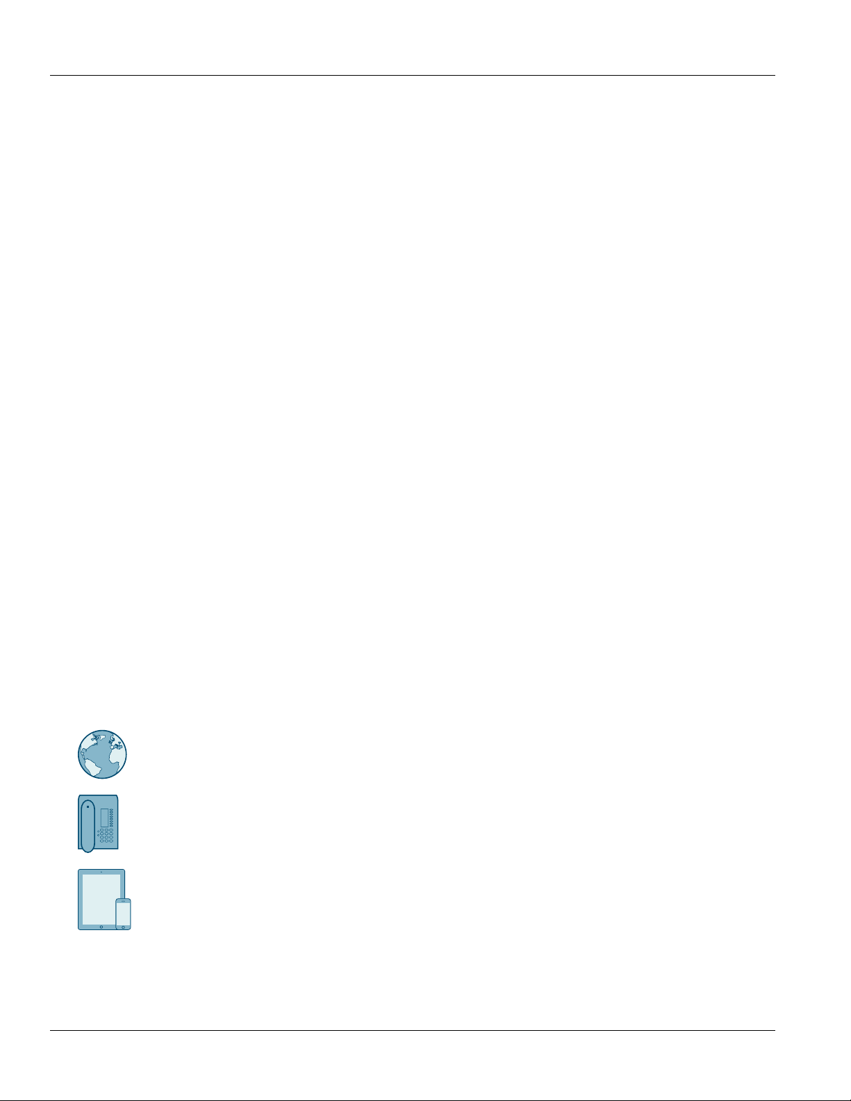
Customer Support
Customer support is available 24 hours, 7 days a week for all Siemens customers. For technical support or general
information, contact Siemens Customer Support through any of the following methods:
Online
Visit http://www.siemens.com/automation/support-request to submit a Support Request (SR) or check on the status of an
existing SR.
Telephone
Call a local hotline center to submit a Support Request (SR). To locate a local hotline center, visit http://
www.automation.siemens.com/mcms/aspa-db/en/automation-technology/Pages/default.aspx .
Mobile App
Install the Industry Online Support app by Siemens AG on any Android, Apple iOS or Windows mobile device and be able to:
• Access Siemens' extensive library of support documentation, including FAQs and manuals
• Submit SRs or check on the status of an existing SR
• Contact a local Siemens representative from Sales, Technical Support, Training, etc.
• Ask questions or share knowledge with fellow Siemens customers and the support community
viii Related Documents
Page 9

RUGGEDCOM RSG2100
Installation Guide
Introduction
The RUGGEDCOM RUGGEDCOM RSG2100 is a rugged, fully managed, modular Ethernet switch specifically
designed to operate reliably in electrically harsh and climatically demanding utility substation, railway and
industrial environments. The RUGGEDCOM RSG2100’s superior rugged hardware design coupled with the
embedded Rugged Operating System (ROS) provides improved system reliability and advanced cyber security and
networking features, making it ideally suited for creating Ethernet networks for mission-critical, real-time, control
applications.
The RUGGEDCOM RSG2100’s modular flexibility offers 10BaseFL/100BaseFX/1000BaseX fiber and
10/100/1000BaseTX copper port combinations. Optional front or rear mount connectors make the RUGGEDCOM
RSG2100 highly versatile for any application and can support multiple fiber connectors (ST, MTRJ, LC, SC) without
loss of port density. The RUGGEDCOM RSG2100 is packaged in a rugged galvanized steel enclosure with industrial
grade DIN, panel, or 48 cm (19 in) rack-mount mounting options.
Chapter 1
Introduction
CONTENTS
• Section1.1, “Feature Highlights”
• Section1.2, “Description”
Section1.1
Feature Highlights
Ethernet Ports
• Up to 3 x Gigabit Ethernet ports (copper and fiber)
• Up to 16 x 100Base-FX Fiber Fast Ethernet ports (copper and fiber)
• 2-port modules for tremendous flexibility
• Non-blocking, store and forward switching
• Supports many types of fiber (multimode, single mode, bidirectional single strand)
• Long haul optics allow Gigabit at distances up to 70 km
• Multiple connector types (ST, MTRJ, LC, SC)
Rated for Reliability in Harsh Environments
• Immunity to EMI and heavy electrical surges
• Zero-Packet-Loss™ technology
• -40 to 85 °C (-40 to 185 °F) operating temperature (no fans)
• Conformal coated printed circuit boards (optional)
• 18 AWG galvanized steel enclosure
• Hazardous Location Certification: Class 1 Division 2
Feature Highlights 1
Page 10
Chapter 1
3
4
2
1
5
7
6
Introduction
RUGGEDCOM RSG2100
Installation Guide
Universal Power Supply Options
• Fully integrated, dual-redundant (optional) power supplies
• Universal high-voltage range: 88-300 VDC or 85-264 VAC
• Screw or pluggable terminal blocks for reliable, maintenance-free connections
• CSA/UL 60950-1 safety approved to 85 °C (185 °F)
Section1.2
Description
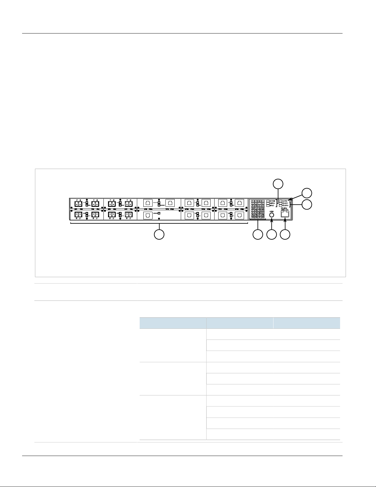
The RUGGEDCOM RSG2100 features various ports, controls and indicator LEDs on the display panel for
connecting, configuring and troubleshooting the device. The display panel can be located on the rear, front or top
of the device, depending on the mounting configuration.
Figure1: RUGGEDCOM RSG2100
1.Fiber or Copper Ethernet Ports 2.Port Status Indicator LEDs 3.Mode Button 4.RS-232 Serial Console Port (RJ45) 5.Display Mode
Indicator LEDs 6.Alarm Indicator LED 7.Power Module Indicator LEDs
Communication Ports Ports for communicating with other devices or accessing the RUGGEDCOM ROS operating
Port Status Indicator LEDs Port status indicator LEDs indicate the operational status of each port, dependent on the
system are described in Chapter3, Communication Ports.
currently selected mode.
Mode Color/State Description
Status
Duplex
Speed
Green (Solid) Link detected
Green (Blinking) Link activity
Off No link detected
Green Full duplex mode
Orange Half duplex mode
Off No link detected
Green (Solid) 100 Mbps
Green (Blinking) 1000 Mbps
Orange (Solid) 10 Mbps
Off No link detected
2 Description
Page 11

RUGGEDCOM RSG2100
Installation Guide
Chapter 1
Introduction
Display Mode Indicator LEDs The display mode indicator LEDs indicate the current display mode for the port status
indicator LEDs (i.e. Status, Duplex or Speed).
Mode button The Mode button sets the display mode for the port status indicator LEDs (i.e. Status, Duplex
or Speed). It can also be used to reset the device if held for 5 seconds.
Alarm Indicator LED The alarm indicator LED illuminates when an alarm condition exists.
Power Module Indicator LEDs The power module indicator LEDs indicate the status of the power modules.
• Green – The power supply is supplying power
• Red – Power supply failure
• Off – No power supply is installed
RS-232 Console Port The serial console port is for interfacing directly with the device and accessing initial
management functions. For information about connecting to the device via the serial
console port, refer to Section2.8, “Connecting to the Device”.
Description 3
Page 12

Chapter 1
Introduction
RUGGEDCOM RSG2100
Installation Guide
4 Description
Page 13
RUGGEDCOM RSG2100
Installation Guide
Installing Device
The following sections describe how to install the device, including mounting the device, installing/removing
modules, connecting power, and connecting the device to the network.
DANGER!
Electrocution hazard – risk of serious personal injury and/or damage to equipment. Before performing
any maintenance tasks, make sure all power to the device has been disconnected and wait
approximately two minutes for any remaining energy to dissipate.
WARNING!
Do not disconnect or open equipment unless power has been switched off or the area is known to be
non-hazardous.
Installing Device
Chapter 2
AVERTISSEMENT !
Débrancher ou ouvrir l'équipment seulement si l'alimnetation a été coupée ou si l'on sait que la zone
ne pose aucun danger.
WARNING!
Substitution of the components may impair suitability for Class I, Division 2.
AVERTISSEMENT !
Le remplacement de composants pourrait compromettre l'admissibilité à la Classe I, Division 2.
WARNING!
Radiation hazard – risk of serious personal injury. This product contains a laser system and is classified
as a CLASS 1 LASER PRODUCT. Use of controls or adjustments or performance of procedures other
than those specified herein may result in hazardous radiation exposure.
IMPORTANT!
This product contains no user-serviceable parts. Attempted service by unauthorized personnel shall
render all warranties null and void.
Changes or modifications not expressly approved by Siemens Canada Ltd could invalidate
specifications, test results, and agency approvals, and void the user's authority to operate the
equipment.
IMPORTANT!
This product should be installed in a restricted access location where access can only be gained by
authorized personnel who have been informed of the restrictions and any precautions that must be
taken. Access must only be possible through the use of a tool, lock and key, or other means of security,
and controlled by the authority responsible for the location.
CONTENTS
• Section2.1, “General Procedure”
5
Page 14
Chapter 2
Installing Device
RUGGEDCOM RSG2100
Installation Guide
• Section2.2, “Required Tools and Materials”
• Section2.3, “Cabling Recommendations”
• Section2.4, “Installing the Device in Hazardous Locations”
• Section2.5, “Mounting the Device”
• Section2.6, “Connecting the Failsafe Alarm Relay”
• Section2.7, “Connecting Power”
• Section2.8, “Connecting to the Device”
• Section2.9, “Configuring the Device”
Section2.1
General Procedure
The general procedure for installing the device is as follows:
1. Review the relevant certification information for any regulatory requirements. For more information, refer to
Section6.1, “Approvals”.
2. Mount the device.
3. Connect the failsafe alarm relay.
4. Connect power to the device and ground the device to safety Earth.
5. Connect the device to the network.
6. Configure the device.
Section2.2
Required Tools and Materials
The following tools and materials are required to install the RUGGEDCOM RSG2100:
Tools/Materials Purpose
AC power cord (16 AWG) For connecting power to the device.
CAT-5 Ethernet cables For connecting the device to the network.
Flathead screwdriver For mounting the device to a DIN rail.
Phillips screwdriver For mounting the device to a panel.
4 x #8-32 screws For mounting the device to a panel.
6 General Procedure
Page 15
RUGGEDCOM RSG2100
Installation Guide
Section2.3
Installing Device
Cabling Recommendations
Before connecting the device, be aware of the recommendations and considerations outlined in this section.
CONTENTS
• Section2.3.1, “Protection On Twisted-Pair Data Ports”
• Section2.3.2, “Gigabit Ethernet 1000Base-TX Cabling Recommendations”
Section2.3.1
Protection On Twisted-Pair Data Ports
All copper Ethernet ports on RUGGEDCOM products include transient suppression circuitry to protect against
damage from electrical transients and conform with IEC 61850-3 and IEEE 1613 Class 1 standards. This means
that during a transient electrical event, communications errors or interruptions may occur, but recovery is
automatic.
Siemens also does not recommend using copper Ethernet ports to interface with devices in the field across
distances that could produce high levels of ground potential rise (i.e. greater than 2500 V), during line-to-ground
fault conditions.
Chapter 2
Section2.3.2
Gigabit Ethernet 1000Base-TX Cabling Recommendations
The IEEE 802.3ab Gigabit Ethernet standard defines 1000 Mbit/s Ethernet communications over distances of up
to 100 m (328 ft) using all 4 pairs in category 5 (or higher) balanced, unshielded twisted-pair cabling. For wiring
guidelines, system designers and integrators should refer to the Telecommunications Industry Association (TIA)
TIA/EIA-568-A wiring standard that characterizes minimum cabling performance specifications required for proper
Gigabit Ethernet operation. For reliable, error-free data communication, new and pre-existing communication
paths should be verified for TIA/EIA-568-A compliance.
The following table summarizes the relevant cabling standards:
Cabling Category
< 5 No New wiring infrastructure required.
5 Yes Verify TIA/EIA-568-A compliance.
5e Yes No action required. New installations should be designed with Category 5e or higher.
6 Yes No action required.
> 6 Yes Connector and wiring standards to be determined.
Follow these recommendations for copper data cabling in high electrical noise environments:
• Data cable lengths should be as short as possible, preferably 3 m (10 ft) in length. Copper data cables should
not be used for inter-building communications.
• Power and data cables should not be run in parallel for long distances, and should be installed in separate
conduits. Power and data cables should intersect at 90° angles when necessary to reduce inductive coupling.
1000Base-
TX Compliant
Required Action
Cabling Recommendations 7
Page 16
Chapter 2
Installing Device
• Shielded/screened cabling can be used when required. Care should be taken to avoid the creation of ground
loops with shielded cabling.
Section2.4
RUGGEDCOM RSG2100
Installation Guide
Installing the Device in Hazardous Locations
The RUGGEDCOM RSG2100 is designed to comply with the safety standards for Class I, Division 2, Zone 2
hazardous locations where concentrations of flammable gases, vapors or liquids may be present, as opposed to
normal operating environments.
Special Conditions for Safe Use
When installing the device in a hazardous location, note the following special conditions for safe use according to
the Canadian Standards Association (CSA):
• The equipment shall be installed in an enclosure that is considered to be not accessible in normal operation
without the use of a tool providing a degree of protection of not less than IP54 according to CSA/UL/IEC/EN
60079-0 and CSA/UL/IEC/EN 60079-15. The enclosure shall have a minimum service temperature range of -40 to
90 °C (-40 to 194 °F).
• The equipment shall be used in an area of not more than pollution degree 2 as defined in IEC/EN 60664-1.
• Transient protection shall be provided that is set at a level not exceeding 140% of the peak rated voltage value
at the supply terminals to the equipment.
• The serial RJ45 console port shall only be used in the safe area.
• The equipment must be appropriately connected to safety Earth upon installation.
• The pluggable communication modules (i.e. SFP transceivers and GBIC optic Ethernet ports) shall not be
connected or disconnected in hazardous locations.
NOTE
For further details of the device's compliance with Class I, Division 2, Zone 2 standards, refer to
Section6.1, “Approvals”.
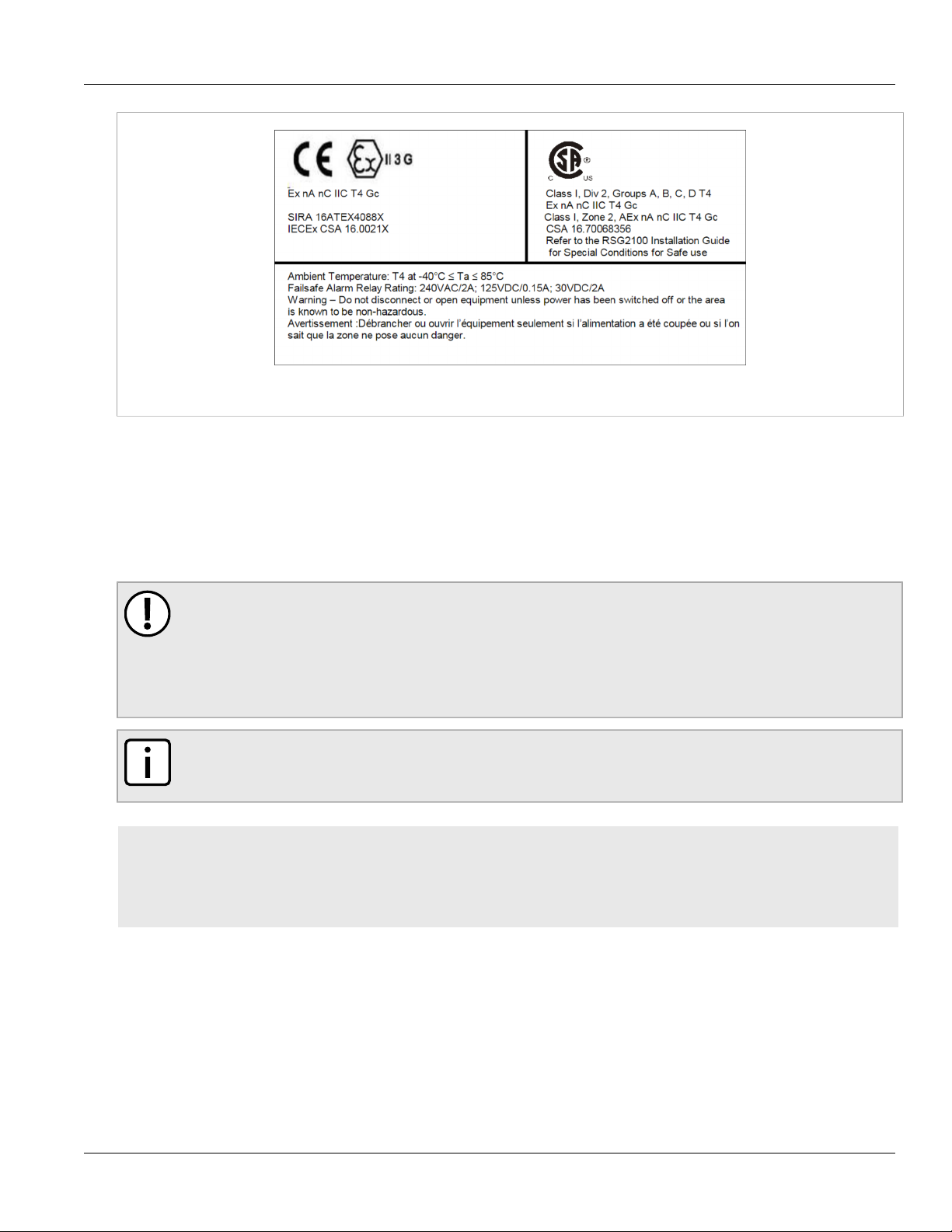
Sample Hazardous Location Label
The following is an example of the RUGGEDCOM RSG2100 hazardous location label:
8 Installing the Device in Hazardous Locations
Page 17
RUGGEDCOM RSG2100
Installation Guide
Figure2:Compliance Label (Example)
Section2.5
Mounting the Device
Installing Device
Chapter 2
The RUGGEDCOM RSG2100 is designed for maximum mounting and display flexibility. It can be equipped with
connectors that allow it to be installed in a 48 cm (19 in) rack, 35 mm (1.4 in) DIN rail, or directly on a panel.
IMPORTANT!
Heat generated by the device is channeled outwards to the enclosure. As such, it is recommended that
2.5 cm (1 in) of space be maintained on all open sides of the device to allow for some convectional
airflow.
Forced airflow is not required. However, any increase in airflow will result in a reduction of ambient
temperature and improve the long-term reliability of all equipment mounted in the rack space.
NOTE
For detailed dimensions of the device with either rack, DIN rail or panel hardware installed, refer to
Chapter5, Dimension Drawings.
CONTENTS
• Section2.5.1, “Mounting the Device to a Rack”
• Section2.5.2, “Mounting the Device on a DIN Rail”
• Section2.5.3, “Mounting the Device to a Panel”
Section2.5.1
Mounting the Device to a Rack
The RUGGEDCOM RSG2100 can be secured to a standard 48 cm (19 in) rack using separately purchased rack
mount adapters. The adapters can be installed at the front or rear of the chassis.
Each adapter kit includes four adapters.
Mounting the Device 9
Page 18

Chapter 2
1 2
3 3
Installing Device
RUGGEDCOM RSG2100
Installation Guide
CAUTION!
Vibration hazard – risk of damage to the device. In high-vibration or seismically active locations,
always install four rack mount adapters (two at the front of the chassis and two at the rear).
CAUTION!
Electrical/mechanical hazard – risk of damage to the device. Before installing the device in a rack,
make sure of the following:
• When installing the device in a closed or multi-device rack, be aware the operating ambient
temperature of the rack may be higher than the ambient temperature of the room. Make sure the
rack is installed in a suitable environment that can withstand the maximum ambient temperature
generated by the rack.
• Make sure each device in the rack is separated by at least one rack-unit of space, or 44 mm (1.75 in),
to promote convectional airflow. Forced airflow is not required. However, any increase in airflow will
result in a reduction of ambient temperature and improve the long-term reliability of all equipment
mounted in the rack space.
• Do not exceed the maximum number of devices or weight restrictions specified by the rack
manufacturer.
• Do not overload the supply circuit. Refer to the over-current protection and power supply ratings
specified by the rack manufacturer.
• Make sure the rack and all devices have a proper ground-to-Earth connection. Pay particular
attention to power supply connections other than direct connections to the branch circuit (e.g. power
strips).
To secure the device to a standard 48 cm (19 in) rack, do the following:
NOTE
The device can be ordered with the communication ports located at the front or rear of the device.
Placing the ports at the rear allows all data and power cabling to be installed and connected at the rear
of the rack.
1. Make sure the rack mount adapters are installed on the correct side of the chassis.
• To make the modules and ports accessible, install the rack mount adapters at the rear of the chassis
• To make the management ports and LEDs accessible, install the rack mount adapters at the front of the
chassis
NOTE
The chassis features multiple mounting holes, allowing the rack mount adapters to be installed up
to 25 mm (1 in) from the face of the device.
Figure3:Rack Mount Adapters
1.Rear 2.Front 3.Rack Mount Adapter
10 Mounting the Device to a Rack
Page 19

RUGGEDCOM RSG2100
2
1
2
3
3
Installation Guide
Installing Device
2. If required, install adapters on the opposite side of the device to protect from vibrations.
3. Insert the device into the rack.
4. Secure the adapters to the rack using the supplied hardware.
Section2.5.2
Mounting the Device on a DIN Rail
For DIN rail installations, the RUGGEDCOM RSG2100 can be equipped with panel/DIN rail adapters pre-installed on
each side of the chassis. The adapters allow the device to be slid onto a standard 35 mm (1.4 in) DIN rail.
IMPORTANT!
DIN rail mounting is not recommended for constant vibration environments.
To mount the device to a DIN rail, do the following:
1. Align the adapters with the DIN rails and slide the device into place.
Chapter 2
Figure4:DIN Rail Mounting
1.Panel/DIN Rail Adapter 2.DIN Rail 3.Screw
2. Install one of the supplied screws on either side of the device to secure the adapters to the DIN rails.
Section2.5.3
Mounting the Device to a Panel
For panel installations, the RUGGEDCOM RSG2100 can be equipped with panel/DIN rail adapters pre-installed on
each side of the chassis. The adapters allow the device to be attached to a panel using screws.
To mount the device to a panel, do the following:
1. Place the device against the panel and align the adapters with the mounting holes.
Mounting the Device on a DIN Rail 11
Page 20

Chapter 2
21
1
Installing Device
RUGGEDCOM RSG2100
Installation Guide
Figure5:Panel Mounting
1.Screw 2.Panel/DIN Rail Adapter
2. Install the supplied screws to secure the adapters to the panel.
Section2.6
Connecting the Failsafe Alarm Relay
The failsafe relay can be configured to latch based on alarm conditions. The NO (Normally Open) contact is closed
when the unit is powered and there are no active alarms. If the device is not powered or if an active alarm is
configured, the relay opens the NO contact and closes the NC (Normally Closed) contact.
NOTE
Control of the failsafe relay output is configurable through ROS. One common application for this relay
is to signal an alarm if a power failure occurs. For more information, refer to the ROS User Guide for
the RUGGEDCOM RSG2100.
The following shows the proper relay connections.
12 Connecting the Failsafe Alarm Relay
Page 21

RUGGEDCOM RSG2100
1
3
2
Installation Guide
Figure6:Failsafe Alarm Relay Wiring
1.Normally Open 2.Common 3.Normally Closed
Section2.7
Installing Device
Chapter 2
Connecting Power
The RUGGEDCOM RSG2100 supports a single or dual redundant AC and/or DC power supplies.
The RUGGEDCOM RSG2100 can be equipped with either a screw-type or pluggable terminal block, which provides
power to both power supplies . The screw-type terminal block is installed using Phillips screws and compression
plates, allowing either bare wire connections or crimped terminal lugs. Use #6 size ring lugs for secure, reliable
connections under severe shock or vibration.
CAUTION!
Electrical hazard – risk of damage to the device. Disconnect the device from the power supply if power
input is above or below the specified input range. For more information, refer to Section4.1, “Power
Supply Specifications”.
NOTE
• For maximum redundancy in a dual power supply configuration, use two independent power
sources.
• Use only #16 gage copper wiring when connecting terminal blocks.
• For 100-240 VAC rated equipment, an appropriately rated AC circuit breaker must be installed.
• A circuit breaker is not required for 12, 24 or 48 VDC rated power supplies.
• It is recommended to provide a separate circuit breaker for each power supply module.
• Equipment must be installed according to applicable local wiring codes and standards.
CONTENTS
• Section2.7.1, “Connecting AC or DC Power”
Connecting Power 13
Page 22

Chapter 2
Installing Device
• Section2.7.2, “Wiring Examples”
Section2.7.1
Connecting AC or DC Power
To connect a single high AC, high DC or low DC power supply to the device, do the following:
CAUTION!
Electrical hazard – risk of damage to equipment. Before testing the dielectric strength (HIPOT) in the
field, remove the metal jumper. This metal jumper connects transient suppression circuitry to chassis
ground and must be removed in order to avoid damage to transient suppression circuitry during
testing.
CAUTION!
Electrical hazard – risk of damage to equipment. Do not connect AC power cables to a DC power supply
terminal block. Damage to the power supply may occur.
IMPORTANT!
Each internal power module is labeled POWER 1 or POWER 2. Make sure to connect the power supply to
the corresponding internal power module.
RUGGEDCOM RSG2100
Installation Guide
1. Remove the terminal block cover.
2. Identify the internal power module (POWER 1 or POWER 2) appropriate for the power supply (AC or DC).
3. Use these screws along with #6 ring lugs to secure the wires to the terminal block.
NOTE
For wiring options, refer to Section2.7.2, “Wiring Examples”.
4. Connect the positive wire from the power source to the positive/live (+/L) terminal on the terminal block.
14 Connecting AC or DC Power
Page 23

RUGGEDCOM RSG2100
4
21
34657465
3
65746
5
2
1
3
Installation Guide
Figure7:Terminal Block Wiring
1.Screw-Type Terminal Block 2.Pluggable Terminal Block 3.Jumper 4.Positive/Live (+/L) Terminal 5.Negative/Neutral (-/N)
Terminal (-/N) 6.Surge Ground Terminal 7.Chassis Ground Terminal
Installing Device
Chapter 2
5. Connect the negative wire from the power source to the negative/neutral (-/N) terminal on the terminal block.
6. Install the supplied metal jumper between terminals 2, 4 and 6 to connect the surge ground terminals to
the chassis ground terminal. The surge ground terminals are used as the ground conductor for all surge and
transient suppression circuitry internal to the unit.
7. Using a #6 ring lug and #6-32 screw, secure the ground terminal on the power source to the chassis ground
terminal on the device. Make sure the lug is tightened to 1.7 N·m (15 lbf·in).
Figure8:Chassis Ground Connection
1.Stainless Steel Stud 2.#6-32 Screw 3.#6 Ring Lug
DANGER!
Electrocution hazard – risk of death, serious personal injury and/or damage to the device. Make
sure the supplied terminal block cover is always installed before the device is powered.
8. Install the terminal block cover.
Connecting AC or DC Power 15
Page 24

Chapter 2
Installing Device
Section2.7.2
Wiring Examples
The following illustrate how to connect power to single and dual power supplies.
RUGGEDCOM RSG2100
Installation Guide
Figure9:Single AC Power Supply
Figure10:Single DC Power Supply
16 Wiring Examples
Page 25

RUGGEDCOM RSG2100
Installation Guide
Figure11:Dual AC Power Supply
Installing Device
Chapter 2
Figure12: Dual DC Power Supply
Wiring Examples 17
Page 26

Chapter 2
18
Installing Device
Figure13: Dual AC/DC Power Supply
RUGGEDCOM RSG2100
Installation Guide
Section2.8
Connecting to the Device
The following describes the various methods for accessing the ROS console and Web interfaces on the device. For
more detailed instructions, refer to the RUGGEDCOM ROS User Guide for the RUGGEDCOM RSG2100.
RS232 Console Port
Connect a workstation directly to the RS232 console port to access the boot-time control and ROS interfaces. The
console port provides access to ROS's console and Web interfaces.
IMPORTANT!
The serial console port is intended to be used only as a temporary connection during initial
configuration or troubleshooting, and should only be used in a safe area (as defined by IEC 60079-0,
Edition 6.0).
Connection to the console port is made using an RJ45-to-DB9 console cable. The following is the pin-out for the
console port:
Pin
Name Description Comment
a
Data Set Ready
a
Carrier Detect Reserved (Do
a
Data Terminal
Ready
Not Connect)
Figure14:RJ45 Console Port Pin Configuration
RJ45
Male
DB9
Female
1 6 DSR
2 1 DCD
3 4 DTR
4 5 GND Signal Ground
18 Connecting to the Device
Page 27

RUGGEDCOM RSG2100
Installation Guide
RJ45
Male
Pin
DB9
Female
Installing Device
Chapter 2
Name Description Comment
a
The DSR, DCD and DTR pins are connected together internally.
b
The CTS and RTS pins are connected together internally.
c
RI is not connected.
5 2 RxD Receive Data
6 3 TxD Transmit Data
7 8 CTS
8 7 RTS
1 9 RI
b
b
c
(to DTE)
(from DTE)
Clear to Send
Read to Send
Ring Indicator
Communication Ports
Connect any of the available Ethernet ports on the device to a management switch and access the ROS console
and Web interfaces via the device's IP address. For more information about available ports, refer to Chapter3,
Communication Ports.
Section2.9
Configuring the Device
Once the device is installed and connected to the network, it must be configured. All configuration management
is done via the RUGGEDCOM ROS interface. For more information about configuring the device, refer to the
RUGGEDCOM ROS User Guide associated with the installed software release.
Configuring the Device 19
Page 28

Chapter 2
Installing Device
RUGGEDCOM RSG2100
Installation Guide
20 Configuring the Device
Page 29

RUGGEDCOM RSG2100
1
3
5
7 9
2
4
6
8
10
Installation Guide
Communication Ports
Communication Ports
The RUGGEDCOM RSG2100 can be equipped with various types of communication ports to enhance its abilities
and performance.
Module Assignment
Chapter 3
Figure15:Module Assignment
Each type of module has a specific location in the RUGGEDCOM RSG2100 chassis:
• Slot 5 supports a pair of Gigabit Ethernet (1 Gbps) ports
• Slot 6 supports a single Gigabit Ethernet (1 Gbps) port
• All other ports support any combination of fiber or copper Ethernet connectors up to 100 Mbps
The exact configuration of the device can be determined by reading the factory data file through the ROS user
interface. For more information about how to read the factory data file, refer to the ROS User Guide for the
RUGGEDCOM RSG2100.
Port LEDs
Each communication port is equipped with an LED that indicates the link/activity state of the port.
21
Page 30

Chapter 3
1
18
Communication Ports
Figure16:Port LEDs
1.Port LED
CONTENTS
• Section3.1, “Copper Ethernet Ports”
• Section3.2, “Fiber Optic Ethernet Ports”
• Section3.3, “SFP Transceivers”
• Section3.4, “GBIC Optic Ethernet Ports”
RUGGEDCOM RSG2100
Installation Guide
LED State Description
Yellow (Solid) Link established
Yellow (Blinking) Link activity
Off No link detected
Section3.1
Copper Ethernet Ports
The RUGGEDCOM RSG2100 supports several 10/100/1000Base-TX Ethernet ports that allow connection to
standard Category 5 (CAT-5) unshielded twisted-pair (UTP) cables with either RJ45 or Micro-D male connectors.
The RJ45 and Micro-D connectors are directly connected to the chassis ground on the device and can accept CAT-5
shielded twisted-pair (STP) cables.
WARNING!
Electric shock hazard – risk of serious personal injury and/or equipment interference. If shielded
cables are used, make sure the shielded cables do not form a ground loop via the shield wire and the
RJ45 receptacles at either end. Ground loops can cause excessive noise and interference, but more
importantly, create a potential shock hazard that can result in serious injury.
Pin-Out
The following are the pin-out descriptions for the RJ45 and Micro-D connectors:
Pin
10/100Base-TX 1000Base-TX
1 RX+ BI_DA+ Receive Data+
Name
Description
or Bi-Directional
Pair A+
Figure17:RJ45 Ethernet Port Pin Configuration
22 Copper Ethernet Ports
2 RX- BI_DA- Receive
Data- or Bi-
Directional Pair A-
Page 31

RUGGEDCOM RSG2100
1
6
Installation Guide
Communication Ports
Chapter 3
Pin
10/100Base-TX 1000Base-TX
3 TX+ BI_DB+ Transmit Data+
4 Reserved (Do
Not Connect)
5 Reserved (Do
Not Connect)
6 TX- BI_DB- Transmit
7 Reserved (Do
Not Connect)
8 Reserved (Do
Not Connect)
Pin 10/100Base-TX 1000Base-TX
1 RX+ A+
Name
Description
or Bi-Directional
Pair B+
BI_DC+ Transmit Data+
or Bi-Directional
Pair C+
BI_DC- Receive
Data- or Bi-
Directional Pair C-
Data- or Bi-
Directional Pair B-
BI_DD+ Receive Data-
or Bi-Directional
Pair D+
BI_DD- Receive
Data- or Bi-
Directional Pair D-
Figure18:Micro-D 10/100Base-TX and 10/100/1000BaseTX Port Pin Configuration
2 Reserved (Do
3 Reserved (Do Not Connect)
4 Reserved (Do
5 TX+ B+
6 RX- A-
7 Reserved (Do
8 Reserved (Do
9 TX- B-
Not Connect)
Not Connect)
Not Connect)
Not Connect)
Specifications
For specifications on the available copper Ethernet ports, refer to Section4.4, “Copper Ethernet Port
Specifications”.
C+
D+
C-
D-
Copper Ethernet Ports 23
Page 32

Chapter 3
21
21
21
21
Communication Ports
Section3.2
Installation Guide
Fiber Optic Ethernet Ports
Fiber optic Ethernet ports are available with either MTRJ (Mechanical Transfer Registered Jack), LC (Lucent
Connector), SC (Standard or Subscriber Connector) or ST (Straight Tip) connectors. Make sure the Transmit (Tx)
and Receive (Rx) connections of each port are properly connected and matched to establish a proper link.
RUGGEDCOM RSG2100
Figure19:MTRJ Port
1.Tx Connector 2.Rx Connector
Figure21:SC Port
1.Tx Connector 2.Rx Connector
Figure20:LC Port
1.Tx Connector 2.Rx Connector
Figure22:ST Port
1.Tx Connector 2.Rx Connector
For specifications on the available fiber optic Ethernet ports, refer to Section4.5, “Fiber Optic Ethernet Port
Specifications”.
Section3.3
SFP Transceivers
The RUGGEDCOM RSG2100 features two Small Form-Factor Pluggable (SFP) transceiver sockets, which are
compatible with a wide array of SFP transceivers available from Siemens.
The following SFP transceivers are compatible with the RUGGEDCOM RSG2100. For more information, including
installation/removal instructions and ordering information, refer to the RUGGEDCOM SFP Transceiver Catalog
[https://support.industry.siemens.com/cs/ca/en/view/109482309] .
IMPORTANT!
Only use SFP transceivers approved by Siemens for RUGGEDCOM products. Siemens accepts no liability
as a result of performance issues related in whole or in part to third-party components.
SFP Transceiver Order Code
RUGGEDCOM SFP1112-1 6GK6000-8CG01-0AA0 10/100/1000
RUGGEDCOM SFP1122-1SX 6GK6000-8FG51-0AA0 1000 MM 0.5
RUGGEDCOM SFP1122-1SX2 6GK6000-8FE58-0AA0 1000 MM 2
RUGGEDCOM SFP1132-1LX10 6GK6000-8FG52-0AA0 1000 SM 10
24 Fiber Optic Ethernet Ports
Speed
(Mbit/s)
b
Mode
CAT-5e
Copper
a
Nominal Distance (km)
0.1
Page 33

RUGGEDCOM RSG2100
21
Installation Guide
Communication Ports
Chapter 3
SFP Transceiver Order Code
RUGGEDCOM SFP1132-1LX25 6GK6000-8FG53-0AA0 1000 SM 25
RUGGEDCOM SFP1132-1LX40 6GK6000-8FG57-0AA0 1000 SM 40
RUGGEDCOM SFP1132-1LX70 6GK6000-8FG54-0AA0 1000 SM 70
RUGGEDCOM SFP1132-1LX100 6GK6000-8FG55-0AA0 1000 SM 100
RUGGEDCOM SFP1132-1LX115 6GK6000-8FE56-0AA0 1000 SM 115
a
MM = Multi-Mode, SM = Single-Mode
b
The RUGGEDCOM RSG2100 supports only 100/1000 Mbit/s.
Section3.4
Speed
(Mbit/s)
Mode
a
Nominal Distance (km)
GBIC Optic Ethernet Ports
GBIC (Gigabit Interface Converter) optic Ethernet ports are available with SC (Standard or Subscriber Connector)
connectors.
Figure23:SC Port
1.Tx Connector 2.Rx Connector
CONTENTS
• Section3.4.1, “Installing a GBIC Optical Port”
• Section3.4.2, “Removing a GBIC Optical Port”
Section3.4.1
Installing a GBIC Optical Port
To install a GBIC optical port, do the following:
WARNING!
Explosion hazard – risk of serious personal injury and/or equipment damage. Do not install or remove
GBIC optical ports when an explosive atmosphere is present.
CAUTION!
Electrical hazard – risk of damage to equipment. Use only components certified by Siemens with
RUGGEDCOM products. Damage to the module and device may occur if compatibility and reliability
have not been properly assessed.
GBIC Optic Ethernet Ports 25
Page 34

Chapter 3
2
1
3
Communication Ports
RUGGEDCOM RSG2100
Installation Guide
CAUTION!
Electrical hazard – risk of damage to equipment. Make sure all electrostatic energy is dissipated before
installing or removing components from the device. An electrostatic discharge (ESD) can cause serious
damage to the component once it is outside the chassis.
IMPORTANT!
Only install GBIC optical ports that are compatible with the RUGGEDCOM RSG2100.
1. Make sure all potential electrostatic build-up has been properly discharged to prevent electrostatic discharges
(ESD). This can be accomplished by wearing an ESD-preventive wrist strap connected to either the chassis
ground connector or a bare metal surface on the router/switch.
2. Remove the dust cover from the port opening in the module.
3. Remove the port from its packaging.
CAUTION!
Mechanical hazard – risk of component damage. GBIC optical ports are designed to insert in only
one orientation. Do not force the port into the module.
4. Remove the dust plug from the socket and store for future use.
5. Squeeze the latches on either side of the port and insert the port into the socket.
Figure24:Installing a GBIC Optical Port
1.GBIC Optical Port Module 2.Socket 3.Locking Latch
6. Release the latches and make sure the port is locked in place.
IMPORTANT!
Only remove the dust plug when ready to connect a cable to the GBIC optical port.
7. Remove the dust cover from the port and store for future use.
8. Remove the dust cap from the cable and immediately connect it to the port.
9. Connect the cable to a network and observe the LED associated with the port. For more information about the
LED, refer to Chapter3, Communication Ports.
26 Installing a GBIC Optical Port
Page 35

RUGGEDCOM RSG2100
2
1
3
Installation Guide
Section3.4.2
Removing a GBIC Optical Port
To remove an GBIC optical port, do the following:
WARNING!
Explosion hazard – risk of serious personal injury and/or equipment damage. Do not install or remove
GBIC optical ports when an explosive atmosphere is present.
CAUTION!
Electrical hazard – risk of damage to equipment. Make sure all electrostatic energy is dissipated before
performing installing or removing components from the device. An electrostatic discharge (ESD) can
cause serious damage to the component once it is outside the chassis.
1. Make sure all potential electrostatic build-up has been properly discharged to prevent an electrostatic
discharge (ESD). This can be accomplished by wearing an ESD-preventive wrist trap connected to either the
chassis ground connector or a bare metal surface on the router/switch.
2. Disconnect the cable from the port and install the dust cap to the cable end.
3. Squeeze the latches on either side of the port and pull it from the socket.
Communication Ports
Chapter 3
Figure25:Removing a GBIC Optical Port
1.Socket 2.GBIC Optical Port 3.Locking Latch
4. Store the port in an ESD-safe bag or other suitable ESD-safe environment, free from moisture and stored at
the proper temperature (-40 to 85 °C or -40 to 185 °F).
5. Insert a dust plug into the socket opening to prevent the ingress of dust and dirt.
Removing a GBIC Optical Port 27
Page 36

Chapter 3
Communication Ports
RUGGEDCOM RSG2100
Installation Guide
28 Removing a GBIC Optical Port
Page 37

RUGGEDCOM RSG2100
Installation Guide
Technical Specifications
This section details the specifications and operating conditions of the device.
CONTENTS
• Section4.1, “Power Supply Specifications”
• Section4.2, “Failsafe Relay Specifications”
• Section4.3, “Supported Networking Standards”
• Section4.4, “Copper Ethernet Port Specifications”
• Section4.5, “Fiber Optic Ethernet Port Specifications”
• Section4.6, “Operating Environment”
• Section4.7, “Mechanical Specifications”
Technical Specifications
Chapter 4
Section4.1
Power Supply Specifications
The RUGGEDCOM RSG2100 can be equipped with the following power supplies:
CAUTION!
Electrical hazard – risk of damage to the device. Disconnect the device from the power supply if power
input is above or below the specified input range.
Hazardous Environments
Power Supply Type
24 VDC 24 VDC 24 VDC 2.0 A(F)
48 VDC 48 VDC 48 VDC 1.0 A(T)
HI (125/250 VDC)
HI (100/240 VAC)
a
(F) denotes fast-acting fuse
b
(T) denotes time-delay fuse.
c
Power consumption varies based on configuration. 10/100Base-TX ports consume roughly 1 W less than fiber optic ports.
d
The HI power supply is the same power supply for both AC and DC.
d
d
Minimum Maximum
125 VDC 250 VDC 600 mA(T)
100 VAC 240 VAC 600 mA(T)
Input Range
Internal Fuse Ratinga
b
Maximum Power
Consumption
28 W
c
Power Supply Specifications 29
Page 38

Chapter 4
Technical Specifications
Non-Hazardous Environments
RUGGEDCOM RSG2100
Installation Guide
Power Supply Type
24 VDC 10 VDC 36 VDC 6.3 A(F)
48 VDC 36 VDC 72 VDC 3.15 A(T)
HI (125/250 VDC)
HI (110/230 VAC)
e
(F) denotes fast-acting fuse
f
(T) denotes time-delay fuse.
g
Power consumption varies based on configuration. 10/100Base-TX ports consume roughly 1 W less than fiber optic ports.
h
The HI power supply is the same power supply for both AC and DC.
h
h
Minimum Maximum
88 VDC 300 VDC 2 A(T)
85 VAC 264 VAC 2 A(T)
Input Range
Internal Fuse Ratinge
Section4.2
Failsafe Relay Specifications
Parameter Value (Resistive Load)
Max Switching Voltage 240 VAC, 125 VDC
Rated Switching Current 2 A @ 240 VAC, 0.15 A @ 125 VDC, 2 A @ 30 VDC
f
Maximum Power
Consumption
28 W
g
Maximum Switching Capacity 150 W, 500 VA
Section4.3
Supported Networking Standards
Standard 10 Mbps Ports 100 Mbps Ports 1000 Mbps Ports Description
IEEE 802.3
IEEE 802.3u
IEEE 802.3x
IEEE 802.3z
IEEE 802.3ab
IEEE 802.3ad
IEEE 802.1D
IEEE 802.1D
IEEE 802.1p
IEEE 802.1Q
ü
ü
ü ü ü
ü
ü
ü
ü ü ü
ü ü ü
ü ü ü
ü ü ü
10BaseT/10BaseFL
100BaseTX/100BaseFX
Flow Control
1000BaseLX
1000BaseTx
Link Aggregation
MAC Bridges
Spanning Tree Protocol (STP)
Class of Service (CoS)
VLAN (Virtual LAN) Tagging
IEEE 802.1w
ü ü ü
Rapid Spanning Tree Protocol (RSTP)
30 Failsafe Relay Specifications
Page 39

RUGGEDCOM RSG2100
Installation Guide
Standard 10 Mbps Ports 100 Mbps Ports 1000 Mbps Ports Description
Technical Specifications
Chapter 4
IEEE 802.1x
IEEE 802.1Q-2005
(formerly 802.1s)
ü ü ü
ü ü ü
Port-Based Network Access Control
Multiple Spanning Tree Protocol (MSTP)
Section4.4
Copper Ethernet Port Specifications
The following details the specifications for copper Ethernet ports that can be ordered with the RUGGEDCOM
RSG2100.
NOTE
• Maximum segment length is greatly dependent on factors such as fiber quality, and the number
of patches and splices. Consult a Siemens sales associate when determining maximum segment
distances.
• All optical power numbers are listed as dBm averages.
• F51 transceivers are rated for -40 to 85 °C (-40 to 185 °F).
Connector Speed Duplex
RJ45 10/100 Mbps FDX/HDX > CAT-5 TIA/EIA T568A/B 100 m (328 ft) 1.5 kV
i
Cable Type
j
Wiring
Standard
k
Maximum
Distance
l
Isolation
m
RJ45 1000 Mbps FDX/HDX > CAT-5 TIA/EIA T568A/B 100 m (328 ft) 1.5 kV
micro-D 10/100 Mbps FDX/HDX > CAT-5 TIA/EIA T568A/B 100 m (328 ft) 1.5 kV
micro-D 1000 Mbps FDX/HDX > CAT-5 TIA/EIA T568A/B 100 m (328 ft) 1.5 kV
i
Auto-Negotiating
j
Shielded or unshielded.
k
Auto-crossover and auto-polarity.
l
Typical distance. Dependent on the number of connectors and splices.
m
RMS 1 minute.
Section4.5
Fiber Optic Ethernet Port Specifications
The following details the specifications for fiber Ethernet ports that can be ordered with the RUGGEDCOM
RSG2100.
Copper Ethernet Port Specifications 31
Page 40

Chapter 4
Technical Specifications
10FL Ethernet Optical Specifications
RUGGEDCOM RSG2100
Installation Guide
Mode
Connector
Type
Cable
Type (µm)
Tx λ (nm)
Tx min
n
(dBm)
Tx max
(dBm)
Rx
Sensitivity
(dBm)
Rx
Saturation
(dBm)
Distance
(typ.) (km)
62.5/125 -16 -9 18
MM ST
n
Typical.
50/125
850
-19.8 -12.8
-34 -11.2 2
Fast Ethernet (10/100 Mbps) Optical Specifications
Mode
Connector
Type
Cable
Type (µm)
Tx λ (nm)
Tx min.
o
(dBm)
Tx max.
(dBm)
Rx
Sensitivity
(dBm)
62.5/125 -19 12
MM ST
50/125
1300
-22.5
-14 -31 -14 2
62.5/125 -19 12
MM SC
50/125
1300
-22.5
-14 -31 -14 2
62.5/125 -19 12
MM MTRJ
50/125
1300
-22.5
-14 -31 -14 2
MM LC 62.5/125 1300 -19 -14 -32 -14 2 13
Rx
Saturation
(dBm)
Maximum
Distance
p
(km)
Power
Budget
(dB)
14.2
Power
Budget
(dB)
8.5
8.5
8.5
SM ST 9/125 1310 -15 -8 -32 -3 20 17
SM SC 9/125 1310 -15 -8 -31 -7 20 16
SM LC 9/125 1310 -15 -8 -34 -7 20 19
SM SC 9/125 1310 -5 0 -34 -3 50 29
SM LC 9/125 1310 -5 0 -35 3 50 30
SM SC 9/125 1310 0 5 -37 0 90 37
SM LC 9/125 1310 0 5 -37 0 90 37
o
Typical.
p
Typical distance. Dependent on the cable type, number of connectors and number of splices.
Gigabit Ethernet (1 Gbps) Optical Specifications
NOTE
These transceivers utilize a distributed feedback (DFB) type laser and are rated for -20 to 85 °C (-4 to
185 °F) operation only.
Mode
Connector
Type
Cable Type
q
(µm)
Tx λ (nm)
r
Tx
Minimum
(dBm)
s
Tx
Maximum
s
(dBm)
Rx
Sensitivity
s
(dBm)
Rx
Saturation
s
(dBm)
Maximum
Distance
t
(km)
Power
Budget
(dB)
MM LC
850 -9 -2.5 -20 0 0.5 11
62.5/125
32 Fiber Optic Ethernet Port Specifications
50/125
Page 41

RUGGEDCOM RSG2100
Installation Guide
Technical Specifications
Chapter 4
Mode
Connector
Type
Cable Type
q
(µm)
Tx λ (nm)
r
Tx
Minimum
s
(dBm)
Tx
Maximum
s
(dBm)
Rx
Sensitivity
s
(dBm)
Rx
Saturation
s
(dBm)
Maximum
Distance
t
(km)
Power
Budget
(dB)
SM SC 9/125 1310 -10 -3 -20 -3 10 10
SM LC 9/125 1310 -9.5 -3 -21 -3 10 11.5
SM SC 9/125 1310 -5 0 -20 -3 25 15
SM LC 9/125 1310 -7 -3 -24 -3 25 17
q
All cabling is duplex type unless specified otherwise.
r
Typical.
s
All optical power numbers are listed as dBm averages.
t
Typical distance. The maximum segment length is greatly dependent on factors such as fiber quality, and the number of patches and splices. Consult a Siemens
sales associates when determining maximum segment distances.
GBIC Gigabit (1 Gbps) Transceiver Specifications
NOTE
GBIC transceivers have a temperature range of -40 to 85 °C (-40 to 185 °F), unless specified otherwise.
Mode
Connector
Type
Cable
Type (µm)
Tx λ (nm)
u
Tx
Minimum
v
(dBm)
Tx
Maximum
v
(dBm)
Rx
Sensitivity
v
(dBm)
Rx
Saturation
v
(dBm)
Maximum
Distance
w
(km)
Power
Budget
(dB)
SM SC 9/125 1310 -9.5 -3 -21 -3 10 11.5
SM SC 9/125 1310 -7 -3 -24 -3 25 17
x
SM
u
Typical.
v
All optical power numbers are listed as dBm averages.
w
Typical distance. The maximum segment length is greatly dependent on factors such as fiber quality, and the number of patches and splices. Consult a Siemens
sales associates when determining maximum segment distances.
x
Operating temperature range of -20 to 85 °C (-4 to 185 °F) .
SC 9/125 1550 0 5 -23 -3 70 23
Section4.6
Operating Environment
Parameter Range Comments
Ambient Operating Temperature -40 to 85 °C (-40 to 185 °F) Ambient Temperature as measured from a 30 cm
Ambient Relative Humidity 5% to 95% Non-condensing
Ambient Storage Temperature -40 to 85 °C (-40 to 185 °F)
radius surrounding the center of the enclosure.
Operating Environment 33
Page 42

Chapter 4
Technical Specifications
Section4.7
Mechanical Specifications
Dimensions Refer to Chapter5, Dimension Drawings
Weight 5.2 kg (11.5 lbs)
Ingress Protection IP40 (1 mm or 0.04 in objects)
Enclosure 18 AWG Galvanized Steel
RUGGEDCOM RSG2100
Installation Guide
34 Mechanical Specifications
Page 43

RUGGEDCOM RSG2100
Installation Guide
Dimension Drawings
Dimension Drawings
Chapter 5
NOTE
All dimensions are in millimeters, unless otherwise stated.
NOTE
Dimensional tolerances are in accordance with ISO 2768-mK, unless otherwise stated.
438.15
285.24
Figure26:Overall Dimensions
303.28
44.45 ± 0.8
35
Page 44

Chapter 5
Dimension Drawings
32.77
21.08
11.68
RUGGEDCOM RSG2100
Installation Guide
479.29
25.40
12.70
28.96
51.05
308.10
6.35
Figure27:Rack Mount Dimensions
4.57
478.79
314.70
6.35
31.75
36
Page 45

RUGGEDCOM RSG2100
MODE
STATUS
SPEED
DUPLEX
ALARM
POWER2
POWER1
57600-N-8-1
CONSOLE
1 2 3 4
5 6 7 8
11 12
9 10
13 14 15 16
17 18 19 20
21 22 23 24
25 26 27 28
29 30 31 32
11.7
159.8
125.5 80.0
158.0 127.5
10.4
7.4
486.4
476.3
38.9
51.6
285.5
134.3 84.1
Installation Guide
Dimension Drawings
Chapter 5
Figure28:Panel and DIN Rail Mount Dimensions
37
Page 46

Chapter 5
Dimension Drawings
RUGGEDCOM RSG2100
Installation Guide
38
Page 47

RUGGEDCOM RSG2100
Installation Guide
Certification
The RUGGEDCOM RSG2100 device has been thoroughly tested to guarantee its conformance with recognized
standards and has received approval from recognized regulatory agencies.
CONTENTS
• Section6.1, “Approvals”
• Section6.2, “EMC and Environmental Type Tests”
Section6.1
Approvals
Chapter 6
Certification
This section details the standards to which the RUGGEDCOM RSG2100 complies.
CONTENTS
• Section6.1.1, “CSA”
• Section6.1.2, “CSA/Sira”
• Section6.1.3, “European Union (EU)”
• Section6.1.4, “FCC”
• Section6.1.5, “FDA/CDRH”
• Section6.1.6, “ISED”
• Section6.1.7, “ISO”
• Section6.1.8, “RoHS”
• Section6.1.9, “Other Approvals”
Section6.1.1
CSA
This device meets the requirements of the following Canadian Standards Association (CSA) standards under
certificate 16.70068356:
• CAN/CSA-C22.2 No. 60950-1
Information Technology Equipment – Safety – Part 1: General Requirements (Bi-National Standard, with UL
60950-1)
• UL 60950-1
Information Technology Equipment – Safety Part 1: General Requirements
Approvals 39
Page 48

Chapter 6
C US
II 3 G
Ex nA nC IIC T4 Gc
Certification
Installation Guide
• CAN/CSA-C22.2 No. 213-M1987
Non-Incendive Electrical Equipment for Use in Class I, Division 2 Hazardous Locations
• CAN/CSA-C22.2 No. 60079-0:15
Explosive Atmospheres – Part 0: Equipment – General Requirements
• CAN/CSA-C22.2 No. 60079-15:16
Electrical Apparatus for Explosive Gas Atmospheres – Part 15: Construction, Test and Marking of Type of
Protection N Electrical Apparatus
• UL 60079-0, Edition 6.0 (2013)
Explosive Atmospheres – Part 0: Equipment – General Requirements
• UL 60079-15, Edition 4.0 (2013)
Explosive Atmospheres – Part 15: Equipment Protection by Type of Protection N
• ANSI/ISA-12.12.01-2013
Non-Incendive Electrical Equipment for Use in Class I and II, Division 2 and Class III, Division 1 and 2 Hazardous
(Classified) Locations
The device is marked with a CSA symbol that indicates compliance with both Canadian and U.S. requirements.
RUGGEDCOM RSG2100
It is specifically approved for use in hazardous locations defined as:
• Class I, Division 2, Groups A, B, C, D T4
• Ex nA nC IIC T4 Gc
• Class I, Zone 2, AEx nA nC IIC T4 Gc
Section6.1.2
CSA/Sira
This device meets the requirements of the following CSA/Sira standards and is approved for use in hazardous
locations under certificates Sira 16ATEX4088X and IECEx CSA 16.0021X:
• 2014/34/EU (ATEX)
ATEX – Directive of the European Parliament and the Council of 26 February 2014 on the Approximation of
the Laws of the Member States Concerning Equipment and Protective Systems Intended for Use in Potentially
Explosive Atmospheres
• IEC 60079-0, Edition 6.0 (2011)/EN 60079-0:2012
Explosive Atmospheres – Part 0: Equipment – General Requirements
• IEC 60079-15, Edition 4.0 (2010)/EN 60079-15:2010
Explosive Atmospheres – Part 15: Equipment Protection by Type of Protection N
The device is marked with an ATEX marking.
40 CSA/Sira
Page 49

RUGGEDCOM RSG2100
Installation Guide
Certification
NOTE
For the maximum ambient temperature, refer to the hazardous location label affixed to the device.
Section6.1.3
European Union (EU)
This device is declared by Siemens Canada Ltd to comply with essential requirements and other relevant provisions
of the following EU directives:
• EN 60950-1
Information Technology Equipment – Safety – Part 1: General Requirements
• EN 61000-6-2
Electromagnetic Compatibility (EMC) – Part 6-2: Generic Standards – Immunity for Industrial Environments
• EN 60825-1
Safety of Laser Products – Equipment Classification and Requirements
• EN 50581
Technical Documentation for the Assessment of Electrical and Electronic Products with Respect to the Restriction
of Hazardous Substances
• EN 55022
Information Technology Equipment – Radio Disturbance Characteristics – Limits and Methods of Measurement
The device is marked with a CE marking and can be used throughout the European community.
Chapter 6
A copy of the CE Declaration of Conformity is available from Siemens Canada Ltd. For contact information, refer to
“Contacting Siemens ”.
Section6.1.4
FCC
This device has been tested and found to comply with the limits for a Class A digital device, pursuant to Part 15 of
the FCC Rules. These limits are designed to provide reasonable protection against harmful interference when the
equipment is operated in a commercial environment.
This device generates, uses and can radiate radio frequency energy and, if not installed and used in accordance
with the instruction manual, may cause harmful interference to radio communications. Operation of this
equipment in a residential area is likely to cause harmful interference in which case users will be required to
correct the interference at their own expense.
IMPORTANT!
Changes or modifications not expressly approved by the party responsible for compliance could void
the user's authority to operate this device.
European Union (EU) 41
Page 50

Chapter 6
Certification
Section6.1.5
RUGGEDCOM RSG2100
Installation Guide
FDA/CDRH
This device meets the requirements of the following U.S. Food and Drug Administration (FDA) standard:
• Title 21 Code of Federal Regulations (CFR) – Chapter I – Sub-chapter J – Radiological Health
Section6.1.6
ISED
This device is declared by Siemens Canada Ltd to meet the requirements of the following ISED (Innovation Science
and Economic Development Canada) standard:
• CAN ICES-3 (A)/NMB-3 (A)
Section6.1.7
ISO
This device was designed and manufactured using a certified ISO (International Organization for Standardization)
quality program that adheres to the following standard:
• ISO 9001:2008
Quality management systems – Requirements
Section6.1.8
RoHS
This device is declared by Siemens Canada Ltd to meet the requirements of the following RoHS (Restriction of
Hazardous Substances) directives for the restricted use of certain hazardous substances in electrical and electronic
equipment:
• China RoHS 2
Administrative Measure on the Control of Pollution Caused by Electronic Information Products
A copy of the Material Declaration is available online at https://support.industry.siemens.com/cs/us/en/
view/109738831.
Section6.1.9
Other Approvals
This device meets the requirements of the following additional standards:
• IEEE 1613
IEEE Standard Environmental and Testing Requirements for Communications Networking Devices in Electric
Power Substations
• IEC 61000-6-2
Electromagnetic Compatibility (EMC) – Part 6-2: Generic Standards – Immunity for Industrial Environments
42 FDA/CDRH
Page 51

RUGGEDCOM RSG2100
Installation Guide
• IEC 61850-3
Communication Networks and Systems in Substations – Part 3: General Requirements
• EN 50121-4
Railway Applications – Electromagnetic Compatibility – Emission and Immunity of the Signaling and
Telecommunications Apparatus
Section6.2
EMC and Environmental Type Tests
The RUGGEDCOM RSG2100 has passed the following Electromagnetic Compatibility (EMC) and environmental
tests.
EMC Type Tests per IEC 61850-3
NOTE
• In the case of an all fiber port configuration, this product meets all Class 2 requirements. Otherwise,
all Class 1 requirements are met for copper ports.
• If the unit contains copper ports, the IEC 1613 conformance is Class 1, during which disturbance
errors may occur but recovery is automatic.
• If the unit contains all fiber ports, the IEC 1613 conformance is Class 2, during which no disturbance
errors will occur.
Chapter 6
Certification
Test Description Test Levels Severity Levels
Enclosure Contact ±8 kVIEC 61000-4-2 ESD
Enclosure Air ±15 kV
IEC 61000-4-3 Radiated RFI Enclosure Ports 20 V/m Note
IEC 61000-4-4 Burst (Fast Transient)
IEC 61000-4-5 Surge
IEC 61000-4-6 Induced (Conducted) RFI
Signal Ports ±4 kV @ 2.5 kHz Note
DC Power Ports
AC Power Ports
Earth Ground Ports
Signal Ports ±4 kV Line-to-Ground,
DC Power Ports ±2 kV Line-to-Ground,
AC Power Ports ±4 kV Line-to-Ground,
Signal Ports
DC Power Ports
AC Power Ports
Earth Ground Ports
±4 kV 4
±2 kV Line-to-Line
±1 kV Line-to-Line
±2 kV Line-to-Line
10 V 3
4
4
3
4
a
a
IEC 61000-4-8 Magnetic Field Enclosure Ports 100 A/m Continuous 5
EMC and Environmental Type Tests 43
Page 52

Chapter 6
Certification
RUGGEDCOM RSG2100
Installation Guide
Test Description Test Levels Severity Levels
1000 A/m for 1 s
IEC 61000-4-11 Voltage Dips
IEC 61000-4-12 Damped Oscillatory
IEC 61000-4-17 Ripple on DC
IEC 61000-4-18 Damped Oscillatory Wave Slow Damped 2.5 kV Common Mode
IEC 61000-4-29 Voltage Dips
IEC 60255-5
and Interrupts
Power Supply
and Interrupts
Dielectric Strength
AC Power Ports 30% for 1 period
60% for 50 periods
100% for 5 periods
100% for 50 periods
Signal Ports
DC Power Ports
AC Power Ports
Signal PortsIEC 61000-4-16 Mains Frequency Voltage
AC and DC Power Ports
DC Power Ports 10% 3
DC Power Ports 30% for 0.1 s
Signal Ports 2 kV (Fail-Safe
2.5 kV Common
1 kV Differential
Mode @1 MHz
30 V Continuous
300 V for 1s
on Power and Signal
1.0 kV Differential
Mode on Power
60% for 0.1 s
100% for 0.05 s
Relay Output)
3
4
3
HV Impulse
a
Siemens-specified severity levels
EMC Immunity Type Tests per IEEE 1613
NOTE
The RUGGEDCOM RSG2100 meets Class 2 requirements for an all-fiber configuration and Class 1
requirements for copper ports. Class 1 allows for temporary communication loss, while Class 2 requires
error-free and interrupted communications.
Description Test Levels
ESD
Enclosure Contact ±2 kV
Enclosure Air ±4 kV
DC Power Ports 2 kV
AC Power Ports 2 kV
Signal Ports 5 kV (Fail-Safe
DC Power Ports
AC Power Ports
Relay Output)
5 kV
±4 kV
±8 kV
44 EMC and Environmental Type Tests
Page 53

RUGGEDCOM RSG2100
Installation Guide
Radiated RFI Enclosure Ports 35 V/m
Chapter 6
Certification
Description Test Levels
±8 kV
±15 kV
Fast Transient
Oscillatory
HV Impulse
Dielectric Strength
Damped Oscillatory
Magnetic Field
Signal Ports 4 kV @ 2.5 kHz
DC Power Ports 4 kV
AC Power Ports 4 kV
Earth Ground Ports 4 kV
Signal Ports 2.5 kV Common Mode @ 1 MHz
DC Power Ports 2.5 kV Common
1 kV differential mode @ 1 MHz
AC Power Ports 2.5 kV Common
1 kV differential mode @ 1 MHz
Signal Ports 5 kV (Fail-Safe Relay Output)
DC Power Ports 5 kV
AC Power Ports 5 kV
Signal Ports 2 kV
DC Power Ports 2 kV
AC Power Ports 2 kV
Enclosure Ports 100 A/m
Environmental Type Tests
Test Description Test Levels Severity Level
IEC 60068-2-1 Cold Temperature Test Ad -40 °C (-40 °F), 16 Hours
IEC 60068-2-2 Dry Heat Test Bd 85 °C (185 °F), 16 Hours
IEC
60068-2-30
IEC
60068-21-1
IEC
60068-21-2
IEC
60068-2-78
IEC
60068-2-14
IEC
60255-21-2
IEC
60255-21-3
Humidity (Damp Heat, Cyclic) Test Db 95% (non-condensing),
Vibration 2g @ 10-150 Hz
Shock 30 g @ 11 ms
Humidity (Damp
Heat, Steady State)
Change of Temperature Test Nb 5 Cycles, -40 to 85°
Bump 10 g @ 16 ms Class 1
Seismic Method A, Class 2 Class 1
Test Cab 10 days @ 55 °C (131 °F)
55 °C (131 °F), 6 cycles
and 93% Relative Humidity
C (40 to 185° F)
EMC and Environmental Type Tests 45
Page 54

Chapter 6
Certification
RUGGEDCOM RSG2100
Installation Guide
46 EMC and Environmental Type Tests
 Loading...