

Page 1
Preface
RUGGEDCOM RS969
Installation Guide
Introduction
Installing the Device
Communication Ports
Technical Specifications
Dimension Drawings
Accessories
Certification
1
2
3
4
5
6
7
6/2014
RC1038-EN-02
Page 2

RUGGEDCOM RS969
Installation Guide
Copyright © 2014 Siemens Canada Ltd.
All rights reserved. Dissemination or reproduction of this document, or evaluation and communication of its contents, is not authorized
except where expressly permitted. Violations are liable for damages. All rights reserved, particularly for the purposes of patent application or
trademark registration.
This document contains proprietary information, which is protected by copyright. All rights are reserved. No part of this document may be
photocopied, reproduced or translated to another language without the prior written consent of Siemens Canada Ltd..
Disclaimer Of Liability
Siemens has verified the contents of this manual against the hardware and/or software described. However, deviations between the product
and the documentation may exist.
Siemens shall not be liable for any errors or omissions contained herein or for consequential damages in connection with the furnishing,
performance, or use of this material.
The information given in this document is reviewed regularly and any necessary corrections will be included in subsequent editions. We
appreciate any suggested improvements. We reserve the right to make technical improvements without notice.
Registered Trademarks
ROX™, Rugged Operating System On Linux™, CrossBow™ and eLAN™ are trademarks of Siemens Canada Ltd.. ROS® is a registered
trademark of Siemens Canada Ltd..
Other designations in this manual might be trademarks whose use by third parties for their own purposes would infringe the rights of the
owner.
Third Party Copyrights
Siemens recognizes the following third party copyrights:
• Copyright © 2004 GoAhead Software, Inc. All Rights Reserved.
Security Information
Siemens provides products and solutions with industrial security functions that support the secure operation of plants, machines, equipment
and/or networks. They are important components in a holistic industrial security concept. With this in mind, Siemens’ products and solutions
undergo continuous development. Siemens recommends strongly that you regularly check for product updates.
For the secure operation of Siemens products and solutions, it is necessary to take suitable preventive action (e.g. cell protection concept)
and integrate each component into a holistic, state-of-the-art industrial security concept. Third-party products that may be in use should also
be considered. For more information about industrial security, visit http://www.siemens.com/industrialsecurity.
To stay informed about product updates as they occur, sign up for a product-specific newsletter. For more information, visit http://
support.automation.siemens.com.
Warranty
Siemens warrants this product for a period of five (5) years from the date of purchase, conditional upon the return to factory for maintenance
during the warranty term. This product contains no user-serviceable parts. Attempted service by unauthorized personnel shall render all
warranties null and void. The warranties set forth in this article are exclusive and are in lieu of all other warranties, performance guarantees
and conditions whether written or oral, statutory, express or implied (including all warranties and conditions of merchantability and fitness for
a particular purpose, and all warranties and conditions arising from course of dealing or usage or trade). Correction of nonconformities in the
manner and for the period of time provided above shall constitute the Seller’s sole liability and the Customer’s exclusive remedy for defective
or nonconforming goods or services whether claims of the Customer are based in contract (including fundamental breach), in tort (including
negligence and strict liability) or otherwise.
For warranty details, visit www.siemens.com/ruggedcom or contact a Siemens customer service representative.
Contacting Siemens
Address
Siemens Canada Ltd.
Industry Sector
300 Applewood Crescent
Concord, Ontario
Canada, L4K 5C7
Telephone
Toll-free: 1 888 264 0006
Tel: +1 905 856 5288
Fax: +1 905 856 1995
E-mail
ruggedcom.info.i-ia@siemens.com
Web
www.siemens.com/ruggedcom
ii
Page 3

RUGGEDCOM RS969
Installation Guide
Table of Contents
Table of Contents
Preface ................................................................................................................ v
Alerts .................................................................................................................................................. v
Related Documents ............................................................................................................................. v
Accessing Documentation .................................................................................................................... v
Training .............................................................................................................................................. vi
Customer Support .............................................................................................................................. vi
Chapter 1
Introduction .......................................................................................................... 1
1.1 Feature Highlights ........................................................................................................................ 1
1.2 Ports, Controls and Indicator LEDs ............................................................................................... 3
Chapter 2
Installing the Device ............................................................................................ 5
2.1 Mounting the Device .................................................................................................................... 5
2.2 Connecting Power ........................................................................................................................ 6
2.2.1 Power Supply Input Connectors Description ........................................................................ 7
2.2.2 Single High AC Power Supply Wiring Examples ................................................................ 10
2.2.3 Single Low DC Power Supply Wiring Examples ................................................................. 11
2.2.4 Dual High AC/DC Power Supplies .................................................................................... 12
2.3 Connecting the Failsafe Alarm Relay ........................................................................................... 13
2.4 Connecting to the Device ........................................................................................................... 14
2.5 Cabling Recommendations ......................................................................................................... 16
2.5.1 Protection On Twisted-Pair Data Ports .............................................................................. 16
2.6 Ingress Protection ...................................................................................................................... 16
Chapter 3
Communication Ports ......................................................................................... 19
3.1 Copper Ethernet Ports ................................................................................................................ 20
3.2 Fiber Optic Ethernet Ports .......................................................................................................... 21
Chapter 4
Technical Specifications ..................................................................................... 23
4.1 Power Supply Specifications ....................................................................................................... 23
4.2 Failsafe Relay Specifications ...................................................................................................... 23
4.3 Copper Data Port Specifications ................................................................................................. 24
iii
Page 4

Table of Contents
RUGGEDCOM RS969
Installation Guide
4.4 Fiber Optic Ethernet Port Specifications ....................................................................................... 24
4.4.1 Fast Ethernet Optical Specifications .................................................................................. 24
4.4.2 Gigabit Ethernet Optical Specifications .............................................................................. 24
4.5 Operating Environment ............................................................................................................... 25
4.6 Mechanical Specifications ........................................................................................................... 25
Chapter 5
Dimension Drawings .......................................................................................... 27
Chapter 6
Accessories ........................................................................................................ 29
6.1 Power (1/unit) ............................................................................................................................ 29
6.2 Console (1/unit) .......................................................................................................................... 30
6.3 Failsafe (1/unit) .......................................................................................................................... 31
6.4 Ethernet (8/unit) ......................................................................................................................... 32
6.5 LC Fiber Optic (2/unit) ................................................................................................................ 34
Chapter 7
Certification ........................................................................................................ 37
7.1 Agency Approvals ...................................................................................................................... 37
7.2 FCC Compliance ........................................................................................................................ 37
7.3 Industry Canada Compliance ...................................................................................................... 37
7.4 EMI and Environmental Type Tests ............................................................................................. 38
7.4.1 IEC 61850-3 Type Tests .................................................................................................. 38
7.4.2 IEEE 1613 Type Tests ..................................................................................................... 39
7.4.3 IEC Environmental Type Tests .......................................................................................... 40
iv
Page 5
RUGGEDCOM RS969
Installation Guide
Preface
This guide describes the RUGGEDCOM RS969. It describes the major features of the device, installation,
commissioning and important technical specifications.
It is intended for use by network technical support personnel who are responsible for the installation,
commissioning and maintenance of the device. It is also recommended for use by network and system planners,
system programmers, and line technicians.
Alerts
The following types of alerts are used when necessary to highlight important information.
DANGER!
DANGER alerts describe imminently hazardous situations that, if not avoided, will result in death or
serious injury.
Preface
WARNING!
WARNING alerts describe hazardous situations that, if not avoided, may result in serious injury and/or
equipment damage.
CAUTION!
CAUTION alerts describe hazardous situations that, if not avoided, may result in equipment damage.
IMPORTANT!
IMPORTANT alerts provide important information that should be known before performing a procedure
or step, or using a feature.
NOTE
NOTE alerts provide additional information, such as facts, tips and details.
Related Documents
Other documents that may be of interest include:
• ROS User Guide for RS969
Accessing Documentation
The latest Hardware Installation Guides and Software User Guides for most RUGGEDCOM products are
available online at www.siemens.com/ruggedcom.
Alerts v
Page 6

Preface
For any questions about the documentation or for assistance finding a specific document, contact a Siemens
sales representative.
RUGGEDCOM RS969
Installation Guide
Training
Siemens offers a wide range of educational services ranging from in-house training of standard courses on
networking, Ethernet switches and routers, to on-site customized courses tailored to the customer's needs,
experience and application.
Siemens' Educational Services team thrives on providing our customers with the essential practical skills to make
sure users have the right knowledge and expertise to understand the various technologies associated with critical
communications network infrastructure technologies.
Siemens' unique mix of IT/Telecommunications expertise combined with domain knowledge in the utility,
transportation and industrial markets, allows Siemens to provide training specific to the customer's application.
For more information about training services and course availability, visit www.siemens.com/ruggedcom or
contact a Siemens sales representative.
Customer Support
Customer support is available 24 hours, 7 days a week for all Siemens customers. For technical support or
general information, please contact Siemens Customer Support through any of the following methods:
• Online
Visit http://www.siemens.com/automation/support-request to submit a Support Request (SR) or check on the
status of an existing SR.
• Telephone
Call a local hotline center to submit a Support Request (SR). To locate a local hotline center, visit http://
www.automation.siemens.com/mcms/aspa-db/en/automation-technology/Pages/default.aspx.
• Mobile App
Install the Industry Online Support app by Siemens AG on any Android, Apple iOS or Windows mobile device
and be able to:
▪ Access Siemens's extensive library of support documentation, including FAQs, manuals, and much more
▪ Submit SRs or check on the status of an existing SR
▪ Find and contact a local contact person
▪ Ask questions or share knowledge with fellow Siemens customers and the support community via the forum
▪ And much more...
vi Training
Page 7

RUGGEDCOM RS969
Installation Guide
Introduction
The RUGGEDCOM RS969 is an industrially hardened, fully managed Ethernet switch providing dual fiber optical
Fast Ethernet or Gigabit ports and eight Fast Ethernet copper ports in an IP65/IP67 rated package for protection
against low pressure jets of water (IP65) or temporary immersion in water (IP67).
Designed to operate reliably in harsh industrial environments the RS969 provides a high level of immunity
to electromagnetic interference and heavy electrical surges typical of environments found in electric utility
substations, factory floors or in curb side traffic control cabinets. An operating temperature range of -40°C to
+85°C coupled with hazardous location certification and IP65/IP67 rated waterproof packaging allows the RS969
to be placed in virtually any location.
The embedded Rugged Operating System (ROS) provides advanced networking features such as Enhanced
Rapid Spanning Tree (eRSTP), Port Rate Limiting and a full array of intelligent functionality for high network
availability and manageability.
The following sections provide more information about the RS969:
• Section 1.1, “Feature Highlights”
• Section 1.2, “Ports, Controls and Indicator LEDs”
Chapter 1
Introduction
Section 1.1
Feature Highlights
Cyber Security Features
• Multi-level passwords
• SSH/SSL encryption
• Enable/disable ports, MAC-based port security
• Port-based network access control (802.1x)
• VLAN (802.1Q) to segregate and secure network traffic
• RADIUS centralized password management
• SNMPv3 encrypted authentication and access security
Ethernet Ports
• Two Fiber Optical Fast Ethernet Ports (100BaseX) with:.IP66/IP67 Rated fiber optical connectors (type LC)
• Eight Fast Ethernet Ports (10/100BaseTX) with IP66/IP67 Rated M12 D-code connectors or IP66/IP67 Rated
shrouded RJ45 style connectors
• Full compliance with IEEE: 802.3, 802.3u and 802.3z
• Non-blocking, store and forward switching
• Full duplex operation and flow control (IEEE 802.3x)
RuggedRated for Reliability in Harsh Environments
• IP67 Rated for protection against immersion in water
• IP66 Rated for protection against high pressure jets of water
Feature Highlights 1
Page 8

Chapter 1
Introduction
• Meets IEEE 1613 (electric utility substations)
• Exceeds IEC 61850-3 (electric utility substations)
• Exceeds IEEE 61800-3 (variable speed drive systems)
• Exceeds IEC 61000-6-2 (generic industrial environment)
• Exceeds NEMA TS-2 (traffic control equipment)
• Hazardous Location Certification: Class 1 Division 2
• -40 to +85°C operating temperature (no fans)
• Conformal coated circuit boards (optional)
• Failsafe output relay for critical failure or error alarming
Universal Power Supply Options
• Fully integrated power supply
• Universal high-voltage range: 88-300VDC or 85-264VAC.
• Popular low-voltage DC ranges: 12, 24, 48 VDC
• Dual redundant, parallel load-sharing power supplies (option)
• Can be powered from different sources for ultimate redundancy
RUGGEDCOM RS969
Installation Guide
• Available with M12 (Mini-Change) or M23 style connectors
• CSA/UL 60950-1 safety approved to +85°C
Simple Plug and Play Operation
• Automatic learning of up to 8192 MAC addresses
• Auto-negotiation on all 10/100BaseTX ports, 100FX on optic fiber ports
• Auto-MDI/MDIX (crossover) on all 10/100BaseTX ports
• LED indicators for link and activity
ROS Advanced Network Management
• Enhanced Rapid Spanning Tree (eRSTP)
• Quality of Service (802.1p) for real-time traffic
• Port rate limiting: 128kbps to 8Mbps
• VLAN (802.1q) with double tagging
• IGMP Snooping for multicast filtering
• Port configuration, status, statistics, mirroring, security
• Loss of link management on fiber ports
• Web-based, Telnet, CLI management interfaces
• SNMP v2 and RMON
• Rich set of diagnostics with logging and alarms
2 Feature Highlights
Page 9
RUGGEDCOM RS969
6
5
2 3
4
1
Installation Guide
Section 1.2
Ports, Controls and Indicator LEDs
Chapter 1
Introduction
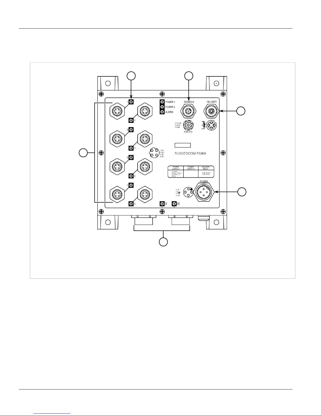
Figure 1: RS969 with M12 D-Core and Mini-Change Power Connector
1. Fast Ethernet Ports - M12 D-Code Connectors 2. LED Indicators 3. Console Port - RS232 4. Failsafe Output Relay 5. Power
Supply - Mini 4-Pole Connector 6. Fiber Optic Ethernet Ports
Ports, Controls and Indicator LEDs 3
Page 10
Chapter 1
6
5
2 3
4
1
Introduction
RUGGEDCOM RS969
Installation Guide
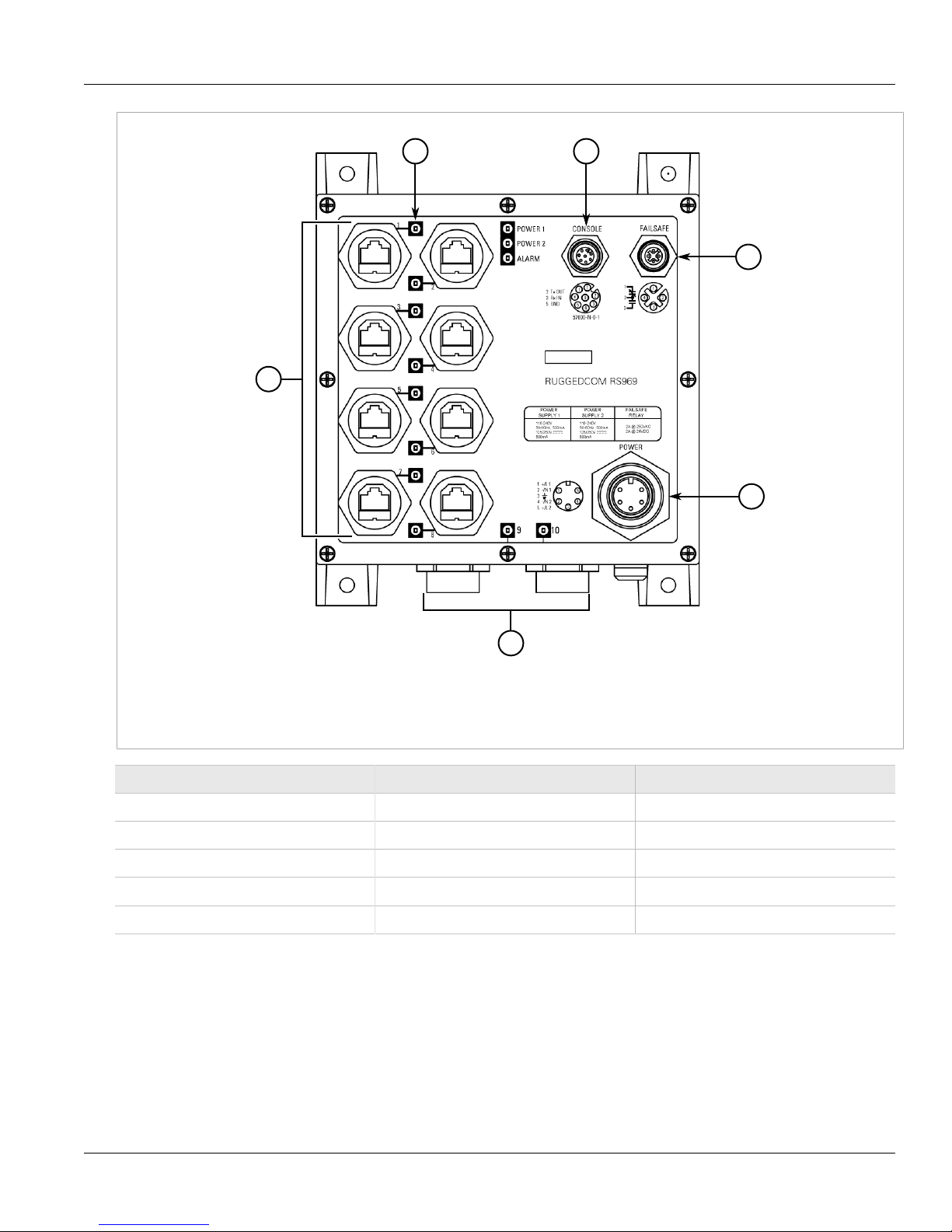
Figure 2: RS969 with RJ45 and M23 Power Connector
1. Fast Ethernet Ports - RJ45 Connectors 2. LED Indicators 3. Console Port - RS232 4. Failsafe Output Relay 5. Power Supply -
M23 Connector 6. Fiber Optic Ethernet Ports
Item Activity Comments
LINK LED (Yellow) Solid Link Established
LINK LED (Yellow) Blinking Tx/Rx Activity
Power 1 LED Solid Power Supply 1 On
Power 2 LED Solid Power Supply 2 On
Alarm LED (Red) Solid Alarm condition exists
4 Ports, Controls and Indicator LEDs
Page 11
RUGGEDCOM RS969
Installation Guide
Installing the Device
Installing the Device
The following sections describe how to install the device, including mounting the device, installing/removing
modules, connecting power, and connecting the device to the network.
WARNING!
Radiation hazard – risk of serious personal injury. This product contains a laser system and is
classified as a CLASS 1 LASER PRODUCT. Use of controls or adjustments or performance of
procedures other than those specified herein may result in hazardous radiation exposure.
DANGER!
Electrocution hazard – risk of serious personal injury and/or damage to equipment. Before performing
any maintenance tasks, make sure all power to the device has been disconnected and wait
approximately two minutes for any remaining energy to dissipate.
IMPORTANT!
This product contains no user-serviceable parts. Attempted service by unauthorized personnel shall
render all warranties null and void.
Changes or modifications not expressly approved by Siemens Canada Ltd. could invalidate
specifications, test results, and agency approvals, and void the user's authority to operate the
equipment.
Chapter 2
IMPORTANT!
This product should be installed in a restricted access location where access can only be gained by
authorized personnel who have been informed of the restrictions and any precautions that must be
taken. Access must only be possible through the use of a tool, lock and key, or other means of security,
and controlled by the authority responsible for the location.
• Section 2.1, “Mounting the Device”
• Section 2.2, “Connecting Power”
• Section 2.3, “Connecting the Failsafe Alarm Relay”
• Section 2.4, “Connecting to the Device”
• Section 2.5, “Cabling Recommendations”
• Section 2.6, “Ingress Protection”
Section 2.1
Mounting the Device
The RS969 is designed to be mounted on a panel by affixing the top and bottom flanges of the device to a panel
using screws.
To mount the device to a panel, do the following:
1. Place the device against the panel and align the flanges with the mounting holes.
Mounting the Device 5
Page 12
Chapter 2
1
Installing the Device
RUGGEDCOM RS969
Installation Guide
Figure 3: Panel Mounting (Typical)
1. Flange
2. Install the supplied screws to secure the flanges to the panel.
Section 2.2
Connecting Power
The following sections describe how to connect power to the device:
• Use only #16 gage copper wiring when connecting terminal blocks.
• Equipment must be installed according to the applicable country wiring codes.
• Section 2.2.1, “Power Supply Input Connectors Description”
• Section 2.2.2, “Single High AC Power Supply Wiring Examples”
• Section 2.2.3, “Single Low DC Power Supply Wiring Examples”
• Section 2.2.4, “Dual High AC/DC Power Supplies”
6 Connecting Power
Page 13
RUGGEDCOM RS969
Installation Guide
Section 2.2.1
Installing the Device
Power Supply Input Connectors Description
The RS969 family has 2 different power supply input connectors: a Mini A-coded male connector or M23 A-code
male connector shown in the figures below. The Mini power connector only has 4 terminals, so only one power
supply source is allowed to connect to the RS969 with the Mini power connector. The M23 power connector
has 5 terminal pins, which means 2 power supply sources are allowed to power the RS969 with the M23 power
connector.
The RS969 family supports dual redundant power supplies – Power Supply 1 (PS1) and Power Supply 2 (PS2).
The connections for PS1 and PS2 are shown in the figures below.
Refer to the table below for a description of each terminal and Section 2.2.2, “Single High AC Power Supply
Wiring Examples” through Section 2.2.4, “Dual High AC/DC Power Supplies” for wiring examples.
Chapter 2
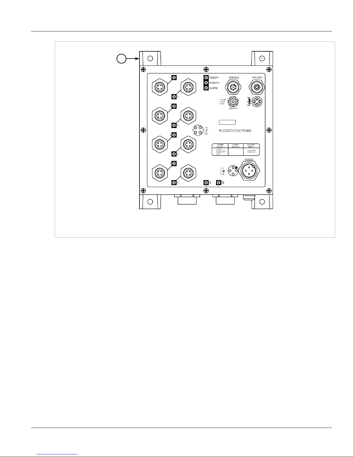
Figure 4: Mini Power Supply Connector
Terminal # Description Usage
1 PS1 Live / + PS1 Live / + is connected to the positive (+) terminal if the power source is DC or
3 Chassis Ground Chassis Ground is connected to the Safety Ground terminal for AC inputs or the
2 PS1 Neutral / - PS1 Neutral / - is connected to the negative (-) terminal if the power source is DC
Power Supply Input Connectors Description 7
to the (Live) terminal if the power source is AC.
equipment ground bus for DC inputs. This terminal 3 is connected to chassis
ground internally in the RS969 family. There is also an additional chassis ground
screw and the chassis ground connects to both power supply surge grounds via a
removable jumper shown in Figure 6 .
or to the (Neutral) terminal if the power source is AC.
Page 14
Chapter 2
Installing the Device
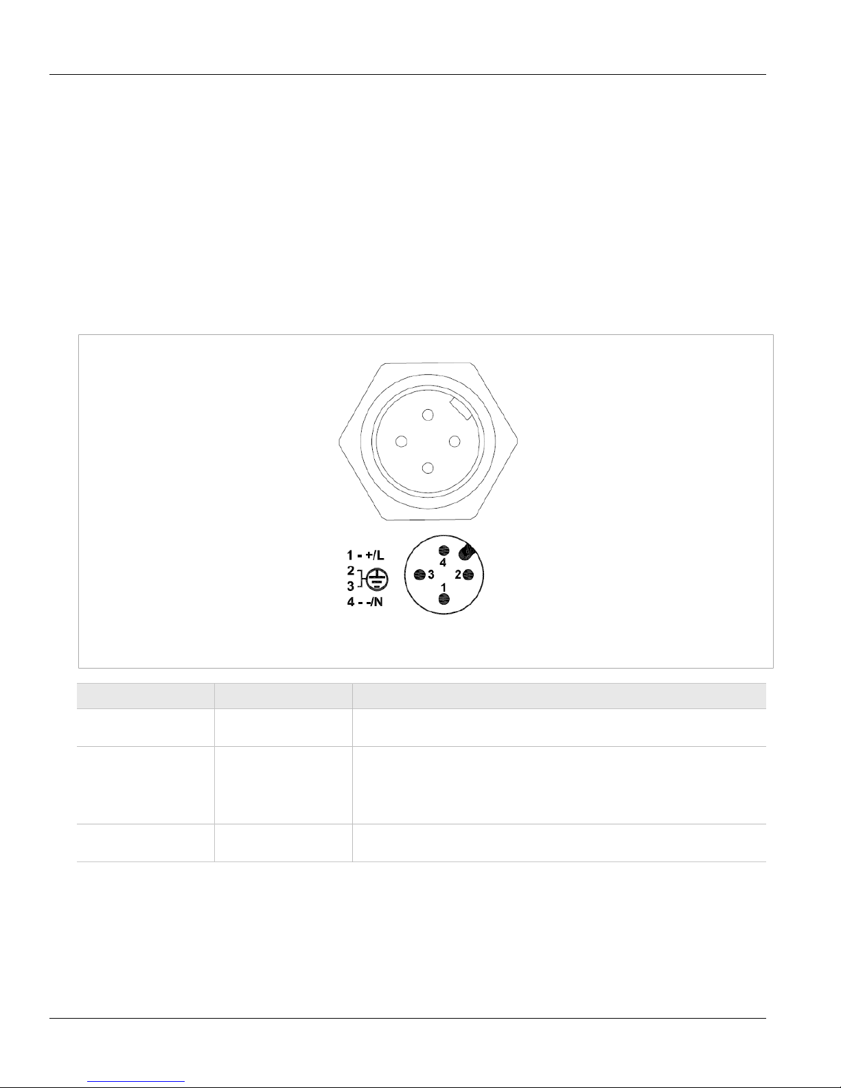
Figure 5: M23 Power Supply Connector
RUGGEDCOM RS969
Installation Guide
Terminal # Description Usage
1 PS1 Live / + PS1 Live / + is connected to the positive (+) terminal if the power source is DC or
2 PS1 Neutral / - PS1 Neutral / - is connected to the negative (-) terminal if the power source is DC
3 Chassis Ground Chassis Ground is connected to the Safety Ground terminal for AC inputs or the
4 PS2 Live / + PS2 Live / + is connected to the positive (+) terminal if the power source is DC or
5 PS2 Neutral / - PS2 Neutral / - is connected to the negative (-) terminal if the power source is DC
to the (Live) terminal if the power source is AC.
or to the (Neutral) terminal if the power source is AC.
equipment ground bus for DC inputs. This terminal 3 is connected to chassis
ground internally in the RS969 family. There is also an additional chassis ground
screw and the chassis ground connects to both power supply surge grounds via a
removable jumper shown in Figure 6 .
to the (Live) terminal if the power source is AC.
or to the (Neutral) terminal if the power source is AC.
8 Power Supply Input Connectors Description
Page 15

RUGGEDCOM RS969
Installation Guide
Figure 6: Surge Ground / Chassis Ground Connection
Installing the Device
Chapter 2
NOTE
• Equipment must be installed according to the applicable country wiring codes.
• All line-to-ground transient energy is shunted to the Surge Ground terminal. In cases where users
require the inputs to be isolated from ground, remove the ground braid between Surge and Chassis
Ground. All line-to-ground transient protection circuitry will be disabled.
Power Supply Input Connectors Description 9
Page 16

Chapter 2
Installing the Device
Section 2.2.2
Single High AC Power Supply Wiring Examples
RUGGEDCOM RS969
Installation Guide
Figure 7: AC Power Supply Wiring Example (M23 Connector)
Figure 8: AC Power Supply Wiring Example (Mini-Change Connector)
NOTE
• 100-240VAC rated equipment: A 250VAC appropriately rated circuit breaker must be installed.
• When equipped with two HI voltage power supplies, independent AC sources can be used to power
the product for greater redundancy.
10 Single High AC Power Supply Wiring Examples
Page 17

RUGGEDCOM RS969
Installation Guide
Section 2.2.3
Single Low DC Power Supply Wiring Examples
Installing the Device
Chapter 2
Figure 9: DC Power Supply Wiring Example (Mini-Change Connector)
Figure 10: DC Power Supply Wiring Example (M23 Connector)
NOTE
• 88-300VDC rated equipment: A 300VDC appropriately rated circuit breaker must be installed.
• A circuit breaker is not required for 12, 24 or 48 VDC rated power supplies.
• For dual DC power supplies, Separate circuit breakers must be installed and separately identified.
Single Low DC Power Supply Wiring Examples 11
Page 18

Chapter 2
Installing the Device
Section 2.2.4
Dual High AC/DC Power Supplies
Figure 11: AC and AC Power Supply Wiring Example
RUGGEDCOM RS969
Installation Guide
Figure 12: DC and DC Power Supply Wiring Example
12 Dual High AC/DC Power Supplies
Page 19

RUGGEDCOM RS969
Installation Guide
Figure 13: DC and AC Power Supply Wiring Example
NOTE
Installing the Device
Chapter 2
• 88-300VDC rated equipment: A 300VDC appropriately rated circuit breaker must be installed.
• A circuit breaker is not required for 12, 24 or 48 VDC rated power supplies.
• Separate circuit breakers must be installed and separately identified.
Section 2.3
Connecting the Failsafe Alarm Relay
The Failsafe output relay is provided to signal critical error conditions that may occur on the RS969 series
switches. The contacts are energized upon power up of the unit and remain energized until a critical error occurs.
The proper relay connections are shown in Figure 14. One common application for this output is to signal an
alarm if a power failure or removal of control power occurs.
Connecting the Failsafe Alarm Relay 13
Page 20

Chapter 2
Installing the Device
Figure 14: Failsafe Alarm Relay Wiring
Section 2.4
RUGGEDCOM RS969
Installation Guide
Connecting to the Device
The following describes the various methods for accessing the ROS console and Web interfaces on the device.
For more detailed instructions, refer to the ROS User Guide for the RS969.
RS232 Console Port
Connect a PC or terminal directly to the RS232 console port to access the boot-time control and ROS interfaces.
The console port provides access to ROS's console and Web interfaces.
IMPORTANT!
The console port is intended to be used only as a temporary connection during initial configuration or
troubleshooting.
Connection to the console port is made using an M12-to-DB9 console cable. The following is the pin-out for the
console port:
14 Connecting to the Device
Page 21

RUGGEDCOM RS969
8
5
7
6
4
1
3
2
9
1
Installation Guide
Pin Name
M12
Male
DB9
Female
1 Reserved (Do Not Connect)
M12
Male
DB9
Female
Installing the Device
Chapter 2
Description
2 3 TX TxD Transmit Data
3 2 RX RxD Receive Data
4 Reserved (Do Not Connect)
5 GND Common Ground
6 Reserved (Do Not Connect)
7 Reserved (Do Not Connect)
8 Reserved (Do Not Connect)
— 9 Reserved (Do Not Connect)
(from DTE)
(from DTE)
Figure 15: M12-to-DB9 Console Port Pin Configuration
Communication Ports
Connect any of the available Ethernet ports on the device to a management switch and access the ROS console
and Web interfaces via the device's IP address. For more information about available ports, refer to Chapter 3,
Communication Ports.
Connecting to the Device 15
Page 22

Chapter 2
Installing the Device
Section 2.5
RUGGEDCOM RS969
Installation Guide
Cabling Recommendations
Siemens recommends using SIMATIC NET industrial Ethernet shielded cables for all Ethernet ports.
Section 2.5.1
Protection On Twisted-Pair Data Ports
Siemens does not recommend the use of copper cabling of any length for critical, real-time substation automation
applications. All copper Ethernet ports on RUGGEDCOM products include transient suppression circuitry
to protect against damage from electrical transients and conform with IEC 61850-3 and IEEE 1613 Class 1
standards. This means that during a transient electrical event, communications errors or interruptions may occur,
but recovery is automatic.
Siemens also does not recommend using copper Ethernet ports to interface with devices in the field across
distances that could produce high levels of ground potential rise (i.e. greater than 2500 V), during line-to-ground
fault conditions.
Section 2.6
Ingress Protection
IEC International Standard 60529 (Edition 2.1: 2001-02) is a "classification of degrees of protection provided
by enclosures as a system for specifying the enclosures of electrical equipment on the basis of the degree of
protection provided by the enclosure." These ratings are determined by specific tests.
The IP number is composed of two numbers, the first referring to the protection against solid objects and the
second against liquids. The higher the IP number, the better the protection. The following chart defines levels of
IP ratings.
1st IP#
Degree of protection against access to hazardous
parts & ingress of solid objects
0 No protection 0 No protection
1 Protected against solid foreign objects of 50 mm Ø and
greater
2 Protected against solid foreign objects of 12.5 mm Ø and
greater
3 Protected against solid foreign objects of 2.5 mm Ø and > 3 Protected against spraying water
4 Protected against solid foreign objects of 1.0 mm Ø and > 4 Protected against splashing water
5 Dust protected 5 Protected against jet-water
6 Dust tight 6 Protected against strong jet-water
2nd
Degree of protection against the ingress of water
IP#
1 Protected against vertically falling water drops
2 Protected against vertically falling water drops when
enclosure tilted up 15°
16 Cabling Recommendations
7 Protected against the effects of temporary submersion in
water
8 Protected against the effects of permanent submersion in
water
Page 23

RUGGEDCOM RS969
Installation Guide
Installing the Device
The RS969 Industrial Ethernet Switch is manufactured and tested to IP67 standards. With an IP67 rating a
product will be "dust tight" and remain completely sealed when immersed in water to a depth of 1 meter for 1
hour. (IEC 60529)
These caps completely seal off unused ports on the IP67 Industrial Ethernet Switch. It has an IP67 rated seal that
keeps out all contaminants like dirt, oil, and water.
Figure 16: Caps
Chapter 2
Ingress Protection 17
Page 24

RUGGEDCOM RS969
Installation Guide
Installing the Device
Chapter 2
Ingress Protection 18
Page 25

RUGGEDCOM RS969
2
1
Installation Guide
Communication Ports
Communication Ports
The RS969 can be equipped with various types of communication ports to enhance its abilities and performance.
To determine which ports are equipped on the device, refer to the factory data file available through ROS. For
more information on how to access the factory data file, refer to the ROS User Guide for the RS969.
Each communication port type has a specific place in the RS969 chassis.
Chapter 3
Figure 17: Port Assignment (M12 Connectors Shown)
1. M12 D-Coded Copper Ethernet Ports 2. Fibre Optic Ethernet Ports
19
Page 26

Chapter 3
2
1
Communication Ports
RUGGEDCOM RS969
Installation Guide
Figure 18: Port Assignment (RJ45 Connectors Shown)
1. RJ45 Copper Ethernet Ports 2. Fibre Optic Ethernet Ports
The following sections describe the available ports:
• Section 3.1, “Copper Ethernet Ports”
• Section 3.2, “Fiber Optic Ethernet Ports”
Section 3.1
Copper Ethernet Ports
The RS969 supports eight 10/100Base-TX Ethernet ports that allow connection to standard Category 5 (CAT-5)
unshielded twisted-pair (UTP) cables with RJ45 male connectors or M12 male connectors. The RJ45/M12
receptacles are directly connected to the chassis ground on the device and can accept CAT-5 shielded twistedpair (STP) cables.
WARNING!
Electric shock hazard – risk of serious personal injury and/or equipment interference. If shielded cables
are used, make sure the shielded cables do not form a ground loop via the shield wire and the RJ45/
M12 receptacles at either end. Ground loops can cause excessive noise and interference, but more
importantly, create a potential shock hazard that can result in serious injury.
20 Copper Ethernet Ports
Page 27

RUGGEDCOM RS969
18
Installation Guide
Each port features a Speed and Link LED that indicates the state of the port.
LED State Description
Yellow The port is operating at 100 MbpsSpeed
Off The port is operating at 10 Mbps
Communication Ports
Chapter 3
Link
Yellow (Solid) Link established
Yellow (Blinking) Link activity
Off No link detected
The following are the pin-out description for the RJ45 and M12 connectors:
Pin 10/100Base-TX Signal Description
1 RX+ Receive Data+
2 RX- Receive Data-
3 TX+ Transmit Data+
Figure 19: RJ45 Ethernet Port Pin Configuration
4 Reserved (Do Not Connect)
5 Reserved (Do Not Connect)
6 TX- Transmit Data-
7 Reserved (Do Not Connect)
8 Reserved (Do Not Connect)
Pin 10/100Base-Tx Signal
1 TX+
2 RX+
3 TX-
4 RX-
Figure 20: 4-Pin D-Coded M12 Ethernet Port Pin
Configuration
For specifications on the available copper Ethernet ports, refer to Section 4.3, “Copper Data Port Specifications”.
Section 3.2
Fiber Optic Ethernet Ports
Fiber optic Ethernet ports are available with an LC (Lucent Connector) connector. Make sure the Transmit (Tx)
and Receive (Rx) connections of each port are properly connected and matched to establish a proper link.
Fiber Optic Ethernet Ports 21
Page 28

Chapter 3
21
Communication Ports
Figure 21: LC Port
1. Tx Connector 2. Rx Connector
For specifications on the available fiber optic Ethernet ports, refer to Section 4.4, “Fiber Optic Ethernet Port
Specifications”.
RUGGEDCOM RS969
Installation Guide
22 Fiber Optic Ethernet Ports
Page 29

RUGGEDCOM RS969
Installation Guide
Technical Specifications
Technical Specifications
The following sections provide important technical specifications related to the device and available modules:
• Section 4.1, “Power Supply Specifications”
• Section 4.2, “Failsafe Relay Specifications”
• Section 4.3, “Copper Data Port Specifications”
• Section 4.4, “Fiber Optic Ethernet Port Specifications”
• Section 4.5, “Operating Environment”
• Section 4.6, “Mechanical Specifications”
Section 4.1
Power Supply Specifications
Chapter 4
Power Supply Type Minimum Input Maximum Input
12–24 VDC 10 VDC 36 VDC 3.15A (T)
24 VDC 18 VDC 36 VDC 3.15A (T)
48 VDC 36 VDC 72 VDC 3.15A (T)
HI (125/250 VDC)
HI (110/230 VAC)
a
(T) denotes time-delay fuse.
b
This is the same power supply for both AC and DC.
b
b
88 VDC
85 VAC
300 VDC
265 VAC
Fuse Rating
3.15A (T)
Section 4.2
Failsafe Relay Specifications
Maximum Switching Voltage Rated Switching Current Isolation
30 VDC 2 A, 60 W
125 VDC 0.24 A, 30 W
125 VAC 0.5 A, 62.5 W
220 VDC 0.24 A, 60 W
Internal
Isolation
a
a
a
ab
1.5 kVDC
1.5 kVDC
1.5 kVDC
4 kVAC
5.5 kVDC
1500 V
rms
Max. Power
Consumption
10 W
for 1 minute
250 VAC 0.25 A, 62.5 W
Power Supply Specifications 23
Page 30

Chapter 4
Technical Specifications
Section 4.3
Copper Data Port Specifications
Data Port Media Distance Connector Type
10/100 Mbps CAT-5 UTP or STP 100 m (49 ft) RJ45 or M12
Section 4.4
Fiber Optic Ethernet Port Specifications
For maximum flexibility, Siemens offers a number of different transceiver choices for fiber optical
communications. The following sections detail fiber optic specifications based on the order code / transceiver
selected at time of ordering.
• Section 4.4.1, “Fast Ethernet Optical Specifications”
• Section 4.4.2, “Gigabit Ethernet Optical Specifications”
RUGGEDCOM RS969
Installation Guide
Section 4.4.1
Fast Ethernet Optical Specifications
Mode Connector
SM LC 9/125 1300 -15/-8 -32 -3 20 17
SM LC 9/125 1300 -5/0 -35 3 50 30
SM LC 9/125 1300 0/5 -37 0 90 37
MM LC 50/125 1300 -22.5/-14 -31 -14 2 8.5
c
Typical.
Section 4.4.2
Cable
Type (µm)
Tx λ (nm)
c
Tx Pwr
(dBm)
(Min/Max)
Rx
Sensitivity
(dBm)
Gigabit Ethernet Optical Specifications
NOTE
• All cabling is duplex type unless otherwise specified.
• Maximum segment length is greatly dependent on factors such as fiber quality, and the number
of patches and splices. Consult a Siemens sales associate when determining maximum segment
distances.
• All optical power numbers are listed as dBm averages.
Rx
Saturation
(dBm)
Typical
Distance
(km)
Power
Budget (dB)
24 Copper Data Port Specifications
Page 31

RUGGEDCOM RS969
Installation Guide
Technical Specifications
Chapter 4
Mode Connector
MM LC
SM LC
SM LC
d
Typical.
Cable
Type (µm)
50/125
62.5/125
8/125
9/125
8/125
9/125
Tx Pwr
Tx λ (nm)
d
(dBm)
(Min/Max)
850 -9.5/-4 -20 0 0.5 14
1310 -9.5/-3 -22 -3 10 17
1310 -7/3 -26 -3 25 19
Rx
Sensitivity
(dBm)
Rx
Saturation
(dBm)
Typical
Distance
(km)
Section 4.5
Operating Environment
Parameter Range Comments
Ambient Operating Temperature -40 to 85° C (-40 to 185° F) Ambient Temperature as measured from a 30 cm (12 in.) radius
Ambient Relative Humidity 5% to 95% Non-condensing
surrounding the center of the RS969 enclosure.
Power
Budget (dB)
Ambient Storage Temperature -40 to 85° C (-40 to 185° F)
IP Rating IP67
Operating Altitude 0 to 15240 m (0 to 50000 ft) Over temperature range of -40 to 85° C (-40 to 185° F)
Section 4.6
Mechanical Specifications
Parameter Value
Dimensions Refer to Chapter 5, Dimension Drawings
Weight 2.5 kg (5.5 lb)
Ingress Protection IP66, IP677
Enclosure Cast Aluminum
Operating Environment 25
Page 32

RUGGEDCOM RS969
Installation Guide
Technical Specifications
Chapter 4
Mechanical Specifications 26
Page 33

RUGGEDCOM RS969
Installation Guide
Dimension Drawings
Dimension Drawings
Chapter 5
NOTE
All dimensions are in inches, unless otherwise stated.
Figure 22: M12 Connectors
27
Page 34

Chapter 5
Dimension Drawings
RUGGEDCOM RS969
Installation Guide
Figure 23: RJ45 Connectors
28
Page 35

RUGGEDCOM RS969
Installation Guide
Accessories
This chapter includes the following information:
• Section 6.1, “Power (1/unit)”
• Section 6.2, “Console (1/unit)”
• Section 6.3, “Failsafe (1/unit)”
• Section 6.4, “Ethernet (8/unit)”
• Section 6.5, “LC Fiber Optic (2/unit)”
Section 6.1
Power (1/unit)
Chapter 6
Accessories
M23 Power Mating Connector
Figure 24: M23 Power Mating Connector
Description: M23 5pin female connector, 600V, IP68
rated
P/N 99-60-0007
Cable specs: 3/18AWG, jacket OD range 0.20" - 0.48"
Power (1/unit) 29
Page 36

Chapter 6
Accessories
Mini Power Mating Cordset
Figure 25: Mini Power Mating Cordset
RUGGEDCOM RS969
Installation Guide
Description: MINI-Change 4pin female connector;
4/16AWG, rubber
P/N 99-43-0183-001
Section 6.2
Console (1/unit)
M12 Console Port Mating Cable
Figure 26: M12 Console Port Mating Cable
Description: M12 8pin A-code male to DB9 female;
unshielded, PUR jacket cable, 30V/4A, 3m
P/N 99-43-0023-001
Cable specs: M12 8pin A-code male to free end, 3m
30 Console (1/unit)
Page 37

RUGGEDCOM RS969
Installation Guide
M12 Console Port Mating Connector
Figure 27: M12 Console Port Mating Connector
Section 6.3
Chapter 6
Accessories
Description: M12-straight plug, 8 pole, A-coded, IP67
rated
P/N 99-60-0002
Failsafe (1/unit)
M12 FailSafe Port Mating Cable
Figure 28: M12 FailSafe Port Mating Cable
Description: M12 4pole A-coded; unshielded, PUR
Jacket cable, 3m
P/N 99-43-0024-001
Failsafe (1/unit) 31
Page 38

Chapter 6
Accessories
M12 FailSafe Port Mating Connector
Figure 29: M12 FailSafe Port Mating Connector
Section 6.4
RUGGEDCOM RS969
Installation Guide
Description: M12-straight plug, 4 pole, A-coded, IP67
rated
P/N 99-60-0009
Ethernet (8/unit)
M12 D-code Ethernet Port Mating Cable
Figure 30: M12 D-code Ethernet Port Mating Cable
Description: M12 D-code to RJ45; patch cable,
3meters
P/N 99-43-0040-001
Cable specs: M12 dcode male 4PIN, CAT5e, 3m
32 Ethernet (8/unit)
Page 39

RUGGEDCOM RS969
Installation Guide
M12 D-code Ethernet Port Mating Connector
Figure 31: M12 D-code Ethernet Port Mating Connector
IP67 RJ45 Ethernet Port Mating Cable
Chapter 6
Accessories
Description: M12-straight plug, 4 pole, D-coded, IP67
rated
P/N 99-60-0008
Description: IP67 RJ45 plug to RJ45; Category 5e
shielded patch cable, 3.1m
P/N 99-43-0182-001
Figure 32: IP67 RJ45 Ethernet Port Mating Cable
Ethernet (8/unit) 33
Page 40

Chapter 6
Accessories
IP67 RJ45 Ethernet Port Mating Connector
Figure 33: IP67 RJ45 Ethernet Port Mating Connector
Section 6.5
RUGGEDCOM RS969
Installation Guide
Description: IP67 RJ45 plug, field attachable
P/N 30-50-0019
LC Fiber Optic (2/unit)
LC Port Mating Connector
Figure 34: LC Port Mating Connector
Description: IP67 Multimode LC plug
P/N 99-60-0006
34 LC Fiber Optic (2/unit)
Page 41

RUGGEDCOM RS969
Installation Guide
Figure 35: LC Port Mating Connector
LC Port Mating Connector
Chapter 6
Accessories
Description: IP67 Singlemode LC plug
P/N 99-60-0002-001
Description: Multimode IP67 LC plug to LC connector,
3m
P/N 99-43-0056-001
Figure 36: LC Port Mating Connector
Figure 37: LC Port Mating Connector
Description: Singlemode IP67 LC plug to LC
connector, 3m
P/N 99-43-0054-001
LC Fiber Optic (2/unit) 35
Page 42

RUGGEDCOM RS969
Installation Guide
Chapter 6
Accessories
LC Fiber Optic (2/unit) 36
Page 43

RUGGEDCOM RS969
Installation Guide
Certification
The RS969 device has been thoroughly tested to guarantee its conformance with recognized standards and has
received approval from recognized regulatory agencies.
• Section 7.1, “Agency Approvals”
• Section 7.2, “FCC Compliance”
• Section 7.3, “Industry Canada Compliance”
• Section 7.4, “EMI and Environmental Type Tests”
Section 7.1
Agency Approvals
Agency Standards Comments
Chapter 7
Certification
CSA CSA C22.2 No. 60950-1, UL 60950-1 Approved
CE EN 60950-1, EN 61000-6-2, EN 55022, EN 60825-1, EN 50581 Approved
FCC FCC Part 15, Class A Approved
FDA/CDRH 21 CFR Chapter I, Sub-chapter J Approved
Section 7.2
FCC Compliance
This equipment has been tested and found to comply with the limits for a Class A digital device pursuant to Part
15 of the FCC Rules. These limits are designed to provide reasonable protection against harmful interference
when the equipment is operated in a commercial environment.
This equipment generates, uses and can radiate radio frequency energy and, if not installed and used in
accordance with the instruction manual, may cause harmful interference to radio communications. Operation of
this equipment in a residential area is likely to cause harmful interference in which case the user will be required
to correct the interference on his own expense.
Section 7.3
Industry Canada Compliance
CAN ICES-3 (A) / NMB-3 (A)
Agency Approvals 37
Page 44

Chapter 7
Certification
Section 7.4
EMI and Environmental Type Tests
This section contains the following information:
• Section 7.4.1, “IEC 61850-3 Type Tests”
• Section 7.4.2, “IEEE 1613 Type Tests”
• Section 7.4.3, “IEC Environmental Type Tests”
Section 7.4.1
IEC 61850-3 Type Tests
Table: IEC 61850-3 Type Tests
RUGGEDCOM RS969
Installation Guide
Test Description Test Levels
Enclosure Contact +/- 8kV 4IEC 61000-4-2 ESD
Enclosure Air +/- 15kV 4
IEC 61000-4-3 Radiated RFI Enclosure ports 20 V/m x
IEC 61000-4-4 Burst (Fast Transient)
IEC 61000-4-5 Surge
IEC 61000-4-6 Induced
(Conducted) RFI
IEC 61000-4-8 Magnetic Field Enclosure ports 40 A/m continuous,1000 A/m for 1 s N/A
Signal ports +/- 4kV @ 2.5kHz x
D.C. Power ports +/- 4kV 4
A.C. Power ports +/- 4kV 4
Earth ground ports +/- 4kV 4
Signal ports +/- 4kV line-to-earth,+/- 2kV line-to-line 4
D.C. Power ports +/- 2kV line-to-earth,+/- 1kV line-to-line 3
A.C. Power ports +/- 4kV line-to-earth,+/- 2kV line-to-line 4
Signal ports 10V 3
D.C Power ports 10V 3
A.C. Power ports 10V 3
Earth ground ports 10V 3
Severity
Levels
Voltage Dips
& Interrupts
IEC 61000-4-11
IEC 61000-4-12 Damped Oscillatory
Voltage
38 EMI and Environmental Type Tests
D.C. Power ports 30% for 0.1s, 60% for 0.1s,100% for 0.05s N/AIEC 61000-4-29
A.C. Power ports
Signal ports 2.5kV common,1kV differential mode @ 1MHz 3
D.C. Power ports 2.5kV common,1kV differential mode @ 1MHz 3
A.C. Power ports 2.5kV common,1kV differential mode @ 1MHz 3
Signal ports 30V Continuous, 300V for 1s 4IEC 61000-4-16 Mains Frequency
D.C. Power ports 30V Continuous, 300V for 1s 4
30% for 1 period,60% for 50 periods N/A
100% for 5 periods,100% for 50 periods
2
N/A
Page 45

RUGGEDCOM RS969
Installation Guide
Chapter 7
Certification
Test Description Test Levels
IEC 61000-4-17 Ripple on D.C.
Power Supply
IEC 60255-5 Dielectric Strength
IEC 60255-5 H.V. Impulse
Section 7.4.2
IEEE 1613 Type Tests
Table: IEEE 1613 Type Tests
IEEE Test IEEE 1613 Clause Description Test Levels
Severity
Levels
D.C. Power ports 10% 3
Signal ports 2 kVAC (Fail-Safe Relay output) N/A
D.C. Power ports 1.5kVDC N/A
A.C. Power ports 2 kVAC N/A
Signal ports 5kV (Fail-Safe Relay output) N/A
D.C. Power ports 5kV N/A
A.C. Power ports 5kV N/A
Enclosure Contact +/- 8kVC37.90.3 9 ESD
Enclosure Air +/- 15kV
C37.90.2 8 Radiated RFI Enclosure ports 35 V/m
C37.90.1 7 Fast Transient
C37.90.1 7 Oscillatory
C37.90 6 H.V. Impulse
C37.90 6 Dielectric Strength
Signal ports +/- 4kV @ 2.5kHz
D.C. Power ports +/- 4kV
A.C. Power ports +/- 4kV
Earth ground ports +/- 4kV
Signal ports 2.5kV common mode @ 1MHz
D.C. Power ports 2.5kV common & differential mode @ 1MHz
A.C. Power ports 2.5kV common & differential mode @ 1MHz
Signal ports 5 kV (Failsafe Relay)
D.C. Power ports 5 kV
A.C. Power ports 5 kV
Signal ports 2kVAC (Failsafe Relay)
D.C. Power ports 1.5 kVDC
A.C. Power ports 2 kVAC
NOTE
• If the unit contains copper ports, the IEEE 1613 conformance is Class 1 (During disturbance, errors
may occur but recovery is automatic).
• If the unit contains all fiber ports, the IEEE 1613 conformance is Class 2 (During disturbance, no
errors will occur).
IEEE 1613 Type Tests 39
Page 46

Chapter 7
Certification
Section 7.4.3
IEC Environmental Type Tests
Table: Environmental Type Tests
Test Description Test Levels Severity Levels
IEC 60068-2-1 Cold Temperature Test Ad -40 deg. C, 16 Hours N/A
IEC 60068-2-2 Dry Heat Test Bd +85 deg. C, 16 Hours N/A
RUGGEDCOM RS969
Installation Guide
IEC 60068-2-30 Humidity (Damp
Heat, Cyclic)
IEC 60255-21-1 Vibration 2g @ (10-150) Hz Class 2
IEC 60255-21-2 Shock 30g @ 11ms Class 2
IEC 60529 (IPx6) Ingress Protection Water Jet 100l/m @ 2.5m
IEC 60529 (IPx7) Ingress Protection Water Submersion 30 min @ 1m
IEC 60529 (IP6x) Ingress Protection Dust Talcum 2kg/m3 for 8h as per 13.4 Cat. 1&2
Test Db 95% (non-condensing),
55 deg. C, 6 cycles
as per 14.2.6
as per 14.2.7
N/A
N/A
N/A
40 IEC Environmental Type Tests
 Loading...