

Page 1
Preface
RUGGEDCOM RS950G
Installation Guide
Introduction
Installing the Device
Device Management
Communication Ports
Technical Specifications
Certification
1
2
3
4
5
6
5/2019
RC1037-EN-05
Page 2

RUGGEDCOM RS950G
Installation Guide
Copyright © 2019 Siemens Canada Ltd
All rights reserved. Dissemination or reproduction of this document, or evaluation and communication of its contents, is not authorized
except where expressly permitted. Violations are liable for damages. All rights reserved, particularly for the purposes of patent application or
trademark registration.
This document contains proprietary information, which is protected by copyright. All rights are reserved. No part of this document may be
photocopied, reproduced or translated to another language without the prior written consent of Siemens Canada Ltd.
Disclaimer Of Liability
Siemens has verified the contents of this document against the hardware and/or software described. However, deviations between the product
and the documentation may exist.
Siemens shall not be liable for any errors or omissions contained herein or for consequential damages in connection with the furnishing,
performance, or use of this material.
The information given in this document is reviewed regularly and any necessary corrections will be included in subsequent editions. We
appreciate any suggested improvements. We reserve the right to make technical improvements without notice.
Registered Trademarks
RUGGEDCOM™ and ROS™ are trademarks of Siemens Canada Ltd.
Other designations in this manual might be trademarks whose use by third parties for their own purposes would infringe the rights of the
owner.
Third Party Copyrights
Siemens recognizes the following third party copyrights:
• Copyright © 2004 GoAhead Software, Inc. All Rights Reserved.
Security Information
Siemens provides products and solutions with industrial security functions that support the secure operation of plants, machines, equipment
and/or networks. They are important components in a holistic industrial security concept. With this in mind, Siemens' products and solutions
undergo continuous development. Siemens recommends strongly that you regularly check for product updates.
For the secure operation of Siemens products and solutions, it is necessary to take suitable preventive action (e.g. cell protection concept) and
integrate each component into a holistic, state-of-the-art industrial security concept. Third-party products that may be in use should also be
considered. For more information about industrial security, visit https://www.siemens.com/industrialsecurity.
To stay informed about product updates as they occur, sign up for a product-specific newsletter. For more information, visit https://
support.automation.siemens.com.
Warranty
Siemens warrants this product for a period of five (5) years from the date of purchase, conditional upon the return to factory for maintenance
during the warranty term. This product contains no user-serviceable parts. Attempted service by unauthorized personnel shall render all
warranties null and void. The warranties set forth in this article are exclusive and are in lieu of all other warranties, performance guarantees
and conditions whether written or oral, statutory, express or implied (including all warranties and conditions of merchantability and fitness for
a particular purpose, and all warranties and conditions arising from course of dealing or usage or trade). Correction of nonconformities in the
manner and for the period of time provided above shall constitute the Seller’s sole liability and the Customer’s exclusive remedy for defective
or nonconforming goods or services whether claims of the Customer are based in contract (including fundamental breach), in tort (including
negligence and strict liability) or otherwise.
For warranty details, visit https://www.siemens.com/ruggedcom or contact a Siemens customer service representative.
ii
Page 3

RUGGEDCOM RS950G
Installation Guide
Contacting Siemens
Address
Siemens Canada Ltd
Industry Sector
300 Applewood Crescent
Concord, Ontario
Canada, L4K 5C7
Telephone
Toll-free: 1 888 264 0006
Tel: +1 905 856 5288
Fax: +1 905 856 1995
E-mail
ruggedcom.info.i-ia@siemens.com
Web
https://www.siemens.com/ruggedcom
iii
Page 4

RUGGEDCOM RS950G
Installation Guide
iv
Page 5

RUGGEDCOM RS950G
Installation Guide
Table of Contents
Table of Contents
Preface ............................................................................................................ vii
Alerts ................................................................................................................................................. vii
Related Documents ............................................................................................................................ viii
Accessing Documentation .................................................................................................................. viii
Training ............................................................................................................................................ viii
Customer Support .............................................................................................................................. viii
Chapter 1
Introduction ..................................................................................................... 1
1.1Feature Highlights ........................................................................................................................ 1
1.2Description ................................................................................................................................... 2
1.3Cabling Recommendations ............................................................................................................ 3
1.4High Availability Seamless Ring Operation ...................................................................................... 3
1.4.1Parallel Redundancy Protocol .............................................................................................. 4
1.4.2High Availability Seamless Redundancy ................................................................................ 4
1.5Decommissioning and Disposal ...................................................................................................... 5
Chapter 2
Installing the Device ......................................................................................... 7
2.1Mounting the Device .................................................................................................................... 7
2.1.1Mounting the Device on a DIN Rail ...................................................................................... 8
2.1.2Mounting the Device to a Panel .......................................................................................... 9
2.2Connecting the Failsafe Alarm Relay .............................................................................................. 9
2.3Connecting Power ....................................................................................................................... 10
2.3.1Connecting High AC/DC Power .......................................................................................... 11
2.3.2Connecting Low DC Power ................................................................................................ 12
Chapter 3
Device Management ....................................................................................... 15
3.1Connecting to the Device ............................................................................................................ 15
Chapter 4
Communication Ports ...................................................................................... 17
4.1Copper Ethernet Ports ................................................................................................................. 18
4.2SFP Transceivers ......................................................................................................................... 18
v
Page 6

Table of Contents
Chapter 5
RUGGEDCOM RS950G
Installation Guide
Technical Specifications .................................................................................. 21
5.1Power Supply Specifications ........................................................................................................ 21
5.2Failsafe Relay Specifications ......................................................................................................... 21
5.3Supported Networking Standards ................................................................................................. 22
5.4Copper Ethernet Port Specifications .............................................................................................. 22
5.5Operating Environment ............................................................................................................... 22
5.6Mechanical Specifications ............................................................................................................ 23
5.7Dimension Drawings ................................................................................................................... 23
Chapter 6
Certification .................................................................................................... 27
6.1Approvals ................................................................................................................................... 27
6.1.1TÜV SÜD ......................................................................................................................... 27
6.1.2European Union (EU) ....................................................................................................... 28
6.1.3 FCC ................................................................................................................................. 28
6.1.4FDA/CDRH ........................................................................................................................ 28
6.1.5 ISED ................................................................................................................................ 29
6.1.6ACMA .............................................................................................................................. 29
6.1.7 RoHS ............................................................................................................................... 29
6.1.8Other Approvals ............................................................................................................... 30
6.2EMC and Environmental Type Tests .............................................................................................. 30
vi
Page 7
RUGGEDCOM RS950G
Installation Guide
Preface
This guide describes the RUGGEDCOM RS950G. It describes the major features of the device, installation,
commissioning and important technical specifications.
It is intended for use by network technical support personnel who are responsible for the installation,
commissioning and maintenance of the device. It is also recommended for use by network and system planners,
system programmers, and line technicians.
CONTENTS
• “Alerts”
• “Related Documents”
• “Accessing Documentation”
• “Training”
• “Customer Support”
Preface
Alerts
The following types of alerts are used when necessary to highlight important information.
DANGER!
DANGER alerts describe imminently hazardous situations that, if not avoided, will result in death or
serious injury.
WARNING!
WARNING alerts describe hazardous situations that, if not avoided, may result in serious injury and/or
equipment damage.
CAUTION!
CAUTION alerts describe hazardous situations that, if not avoided, may result in equipment damage.
IMPORTANT!
IMPORTANT alerts provide important information that should be known before performing a procedure
or step, or using a feature.
NOTE
NOTE alerts provide additional information, such as facts, tips and details.
Alerts vii
Page 8
Preface
Installation Guide
Related Documents
Other documents that may be of interest include:
• RUGGEDCOM ROS User Guide [https://support.industry.siemens.com/cs/ww/en/view/109737321]
• RUGGEDCOM SFP Transceiver Catalog [https://support.industry.siemens.com/cs/ww/en/view/109482309]
Accessing Documentation
The latest user documentation for RUGGEDCOM RS950G is available online at
https://www.siemens.com/ruggedcom. To request or inquire about a user document, contact Siemens Customer
Support.
Training
RUGGEDCOM RS950G
Siemens offers a wide range of educational services ranging from in-house training of standard courses on
networking, Ethernet switches and routers, to on-site customized courses tailored to the customer's needs,
experience and application.
Siemens' Educational Services team thrives on providing our customers with the essential practical skills to make
sure users have the right knowledge and expertise to understand the various technologies associated with critical
communications network infrastructure technologies.
Siemens' unique mix of IT/Telecommunications expertise combined with domain knowledge in the utility,
transportation and industrial markets, allows Siemens to provide training specific to the customer's application.
For more information about training services and course availability, visit https://www.siemens.com/ruggedcom or
contact a Siemens Sales representative.
Customer Support
Customer support is available 24 hours, 7 days a week for all Siemens customers. For technical support or general
information, contact Siemens Customer Support through any of the following methods:
Online
Visit http://www.siemens.com/automation/support-request to submit a Support Request (SR) or check
on the status of an existing SR.
Telephone
Call a local hotline center to submit a Support Request (SR). To locate a local hotline center, visit http://
www.automation.siemens.com/mcms/aspa-db/en/automation-technology/Pages/default.aspx.
Mobile App
Install the Industry Online Support app by Siemens AG on any Android, Apple iOS or Windows mobile
device and be able to:
• Access Siemens' extensive library of support documentation, including FAQs and manuals
viii Related Documents
Page 9

RUGGEDCOM RS950G
Installation Guide
Preface
• Submit SRs or check on the status of an existing SR
• Contact a local Siemens representative from Sales, Technical Support, Training, etc.
• Ask questions or share knowledge with fellow Siemens customers and the support community
Customer Support ix
Page 10

Preface
RUGGEDCOM RS950G
Installation Guide
x Customer Support
Page 11

RUGGEDCOM RS950G
Installation Guide
Introduction
The RUGGEDCOM RS950G is an IEC 62439-3 PRP (Parallel Redundancy Protocol) and HSR (High-Availability
Seamless Redundancy) redundancy box, or RedBox. The RUGGEDCOM RS950G provides the ultimate in network
reliability with Zero-Packet-Loss™ and zero fail-over time from any network fault.
IMPORTANT!
This is a class A product. In a domestic environment this product may cause radio interference in which
case the user may be required to take adequate measures.
IMPORTANT!
Comité International Spécial des Perturbations Radioélectriques Statement - CISPR22 Class A
IMPORTANT!
This class A digital apparatus complies with Canadian ICES-003.
Chapter 1
Introduction
IMPORTANT!
Cet appareil numérique de la classe A est conforme à la norme NMB-003 du Canada.
CONTENTS
• Section1.1, “Feature Highlights”
• Section1.2, “Description”
• Section1.3, “Cabling Recommendations”
• Section1.4, “High Availability Seamless Ring Operation”
• Section1.5, “Decommissioning and Disposal”
Section1.1
Feature Highlights
Network Resilience
• IEC 62439 PRP
• IEC 62439 HSR
Industrial Design
• Panel or DIN mounting
• Dual DC inputs:
▫ 10 to 36 VDC
▫ 37 to 72 VDC
• Universal AC input:
▫ 85-264 VAC or 88-300 VDC
Substation Rated
• -40 to 85 °C (-40 to 185 °F) operating (no fans)
Management
• SSH/SSL encryption
• Web-based, Telnet
• Alarms, Critical Relay
Feature Highlights 1
Page 12
Chapter 1
5
5
3
4
2
1
8
5
9
10
6
7
6
7
6
7
Introduction
• 20 AWG steel enclosure
Section1.2
Description
The RUGGEDCOM RS950G features various ports, controls and indicator LEDs for connecting, configuring and
troubleshooting the device. The final device configuration is determined during the ordering process. The
following describes the major options available.
RUGGEDCOM RS950G
Installation Guide
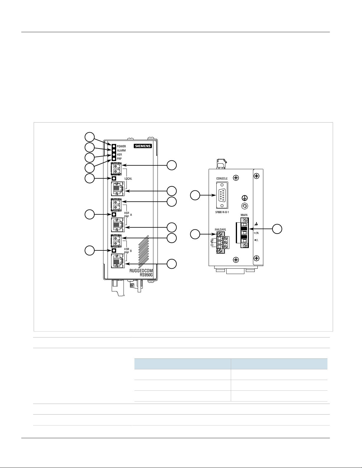
Figure1:RUGGEDCOM RS950G
1.POWER LED 2.ALARM LED 3.HSR LED 4.PRP LED 5.Port Status LED 6.SFP Pluggable Fiber Transceiver 7.Copper Ethernet Port
8.RS-232 Console Port 9.Failsafe Alarm Relay Terminal 10.Power Supply Terminal
LEDs LEDs indicate the operational status of the device.
POWER LED Illuminates when power is being supplied to the device.
ALARM LED Illuminates when an alarm condition exists.
HSR LED Illuminates when the device is in HSR Redbox mode.
State Description
Green Device is ready
Red Device is booting up
Off No power
2 Description
Page 13
RUGGEDCOM RS950G
Installation Guide
PRP LED Illuminates when the device is in PRP Redbox mode.
Port Status LEDs Indicate the status of each port:
State Description
Solid Link established
Blinking Link activity
Off No link/activity
Chapter 1
Introduction
Communication Ports Receive and transmit network traffic, as well as provide remote Web access to the
RS232 Serial Console Port For interfacing directly with the device and accessing initial management functions. For
Failsafe Alarm Relay Terminal Latches to default state when a power disruption or other alarm condition occurs. For more
Power Supply Terminal A pluggable terminal block. For more information, refer to:
Section1.3
RUGGEDCOM ROS operating system. For more information, refer to:
• Section3.1, “Connecting to the Device”
• Section4.1, “Copper Ethernet Ports”
• Section5.4, “Copper Ethernet Port Specifications”
• Section4.2, “SFP Transceivers”
information about connecting to the device via the serial console port, refer to Section3.1,
“Connecting to the Device”.
information, refer to:
• Section2.2, “Connecting the Failsafe Alarm Relay”
• Section5.2, “Failsafe Relay Specifications”
• Section2.3, “Connecting Power”
• Section5.1, “Power Supply Specifications”
Cabling Recommendations
All copper Ethernet ports on RUGGEDCOM products include transient suppression circuitry to protect against
damage from electrical transients and conform with IEC 61850-3 and IEEE 1613 Class 1 standards. This means
that during a transient electrical event, communications errors or interruptions may occur, but recovery is
automatic.
Siemens does not recommend using copper Ethernet ports to interface with devices in the field across distances
that could produce high levels of ground potential rise (i.e. greater than 2500 V), during line-to-ground fault
conditions.
Section1.4
High Availability Seamless Ring Operation
Parallel Redundancy Protocol (PRP) and High-availability Seamless Redundancy (HSR) are two mechanisms defined
by the IEC 62439-3 standard to provide hitless network recovery. Unlike Spanning Tree Protocol (STP), which
Cabling Recommendations 3
Page 14

Chapter 1
5
2
3
4
1
7
6
2
Introduction
RUGGEDCOM RS950G
Installation Guide
requires reconfiguration of the active network topology over redundant physical links, HSR and PRP provide hitless
network recovery through the use of information replication.
CONTENTS
• Section1.4.1, “Parallel Redundancy Protocol”
• Section1.4.2, “High Availability Seamless Redundancy”
Section1.4.1
Parallel Redundancy Protocol
Parallel Redundancy Protocol (PRP) provides hitless network recovery by replicating information over two
physically independent Ethernet networks. The following illustrates a typical PRP network:
Figure2:PRP Network Design
1.Sending IED 2.RUGGEDCOM RS950G 3.Network A 4.Network B 5.RS900 6.IED 7.Receiving IED
NOTE
PRP expands the Ethernet frame by 6 octets due to RCT (Redundancy Check Trailer). Generation of PRP
supervision frames also consumes bandwidth. As a result, the network designer should keep in mind
the overhead introduced by the PRP network when calculating the network capacity.
Section1.4.2
High Availability Seamless Redundancy
The basic principle behind High-availability Seamless Redundancy (HSR) is the replication of frames over both sides
of the HRS ring. The following illustrates a typical HSR network:
4 Parallel Redundancy Protocol
Page 15

RUGGEDCOM RS950G
3
2
1
5
4
2
2
2
Installation Guide
Chapter 1
Introduction
Figure3:HSR Network Design
1.Sending IED 2.RUGGEDCOM RS950G 3.RS900 4.IED 5.Receiving IED
All of the network nodes inside an HSR ring must be HSR-capable. HSR-unaware nodes can be attached to the HSR
ring through the use of a RedBox (Redundancy Box). Compared to PRP, HSR only demands approximately half of
the network infrastructure. However, network bandwidth on an HSR ring is approximately halved compared with a
network ring based on RSTP technology.
NOTE
Current HSR implementation limits link utilization to 74% when using multicast traffic.
Section1.5
Decommissioning and Disposal
Proper decomissioning and disposal of this device is important to prevent malicious users from obtaining
proprietary information and to protect the environment.
Decommissioning
This device may include sensitive, proprietary data. Before taking the device out of service, either permanently or
for maintenance by a third-party, make sure it has been fully decommissioned.
For more information, refer to the associated User Guide.
Decommissioning and Disposal 5
Page 16

Chapter 1
Introduction
Recycling and Disposal
For environmentally friendly recycling and disposal of this device and related accessories, contact a facility
certified to dispose of waste electrical and electronic equipment. Recycling and disposal must be done in
accordance with local regulations.
RUGGEDCOM RS950G
Installation Guide
6 Decommissioning and Disposal
Page 17

RUGGEDCOM RS950G
Installation Guide
Installing the Device
This section describes how to install the device, including mounting the device, connecting power, and
connecting the device to the network.
DANGER!
Electrocution hazard – risk of serious personal injury and/or damage to equipment. Before performing
any maintenance tasks, make sure all power to the device has been disconnected and wait
approximately two minutes for any remaining energy to dissipate.
WARNING!
Radiation hazard – risk of serious personal injury. This product contains a laser system and is classified
as a CLASS 1 LASER PRODUCT. Use of controls or adjustments or performance of procedures other
than those specified herein may result in hazardous radiation exposure.
Installing the Device
Chapter 2
IMPORTANT!
This product contains no user-serviceable parts. Attempted service by unauthorized personnel shall
render all warranties null and void.
Changes or modifications not expressly approved by Siemens Canada Ltd could invalidate
specifications, test results, and agency approvals, and void the user's authority to operate the
equipment.
IMPORTANT!
This product should be installed in a restricted access location where access can only be gained by
authorized personnel who have been informed of the restrictions and any precautions that must be
taken. Access must only be possible through the use of a tool, lock and key, or other means of security,
and controlled by the authority responsible for the location.
CONTENTS
• Section2.1, “Mounting the Device”
• Section2.2, “Connecting the Failsafe Alarm Relay”
• Section2.3, “Connecting Power”
Section2.1
Mounting the Device
The RUGGEDCOM RS950G is designed for maximum mounting and display flexibility. It can be equipped with
connectors that allow it to be installed in a 35 mm (1.4 in) DIN rail or directly on a panel.
Mounting the Device 7
Page 18

Chapter 2
1
1
2
Installing the Device
RUGGEDCOM RS950G
Installation Guide
NOTE
For detailed dimensions of the device with either DIN rail or panel hardware installed, refer to
Section5.7, “Dimension Drawings”.
CONTENTS
• Section2.1.1, “Mounting the Device on a DIN Rail”
• Section2.1.2, “Mounting the Device to a Panel”
Section2.1.1
Mounting the Device on a DIN Rail
For DIN rail installations, the RUGGEDCOM RS950G can be ordered with a DIN rail mounting bracket pre-installed
on the rear of the chassis. The bracket allow the device to be slid onto a standard 35 mm (1.4 in) DIN rail.
IMPORTANT!
DIN rail mounting is not recommended for constant vibration environments.
To mount the device to a DIN rail, do the following:
1. Pull the DIN rail adapter down and clip the device on to the DIN rail. Release the adapter to secure the device.
Figure4:DIN Rail Mounting
8 Mounting the Device on a DIN Rail
1.DIN Rail 2.DIN Rail Mounting Bracket
2. Slide the device into position.
Page 19

RUGGEDCOM RS950G
31211
Installation Guide
Section2.1.2
Installing the Device
Mounting the Device to a Panel
For panel installations, the RUGGEDCOM RS950G can be ordered with mounting brackets that mount to the top
and bottom of the chassis.
To mount the device to a panel, do the following:
1. Remove the bracket mounting screws from the top and bottom of the chassis.
2. Install the mounting brackets to the top and bottom of the chassis using the bracket mounting screws. Make
sure the screws are hand-tightened.
3. Place the device against the panel and align the mounting brackets with the mounting holes.
Chapter 2
Figure5:Panel Mounting
1.Bracket Mounting Screw 2.#6 Screw 3.Mounting Bracket
4. Using #6 screws of sufficient length (not provided), secure the mounting brackets to the panel. Use wall
anchors (not provided) where required.
Section2.2
Connecting the Failsafe Alarm Relay
The failsafe relay can be configured to latch based on alarm conditions. The NO (Normally Open) contact is closed
when the unit is powered and there are no active alarms. If the device is not powered or if an active alarm is
configured, the relay opens the NO contact and closes the NC (Normally Closed) contact.
Mounting the Device to a Panel 9
Page 20

Chapter 2
2 31
Installing the Device
NOTE
Control of the failsafe relay output is configurable through ROS. One common application for this relay
is to signal an alarm if a power failure occurs. For more information, refer to the ROS User Guide for
the RUGGEDCOM RS950G.
The following shows the proper relay connections.
Figure6:Failsafe Alarm Relay Wiring
1.Normally Open 2.Common 3.Normally Closed
RUGGEDCOM RS950G
Installation Guide
Section2.3
Connecting Power
The RUGGEDCOM RS950G supports a single integrated high AC/DC or low DC power supply
IMPORTANT!
• For 110/230 VAC rated equipment, an appropriately rated AC circuit breaker must be installed.
• For 125/250 VDC rated equipment, an appropriately rated DC circuit breaker must be installed.
• Use minimum #16 gage wiring when connecting terminal blocks.
• Equipment must be installed according to applicable local wiring codes and standards.
• All line-to-ground transient energy is shunted to the Surge Ground terminal. In cases where users
require the inputs to be isolated from ground, remove the ground braid between Surge and Chassis
Ground. Note that all line-to-ground transient protection circuitry will be disabled.
IMPORTANT!
Siemens requires the use of external surge protection in VDSL applications where the line may be
subject to surges greater than that for which the device is rated. Use the following specifications as a
guide for VDSL external surge protection:
• Clamping Voltage: 50 V to 200 V
• Insertion Loss: < 0.1 dB at 10 MHz
• Peak Surge Current: 10 kA, 8x20µs waveform
CONTENTS
• Section2.3.1, “Connecting High AC/DC Power”
10 Connecting Power
Page 21

RUGGEDCOM RS950G
1 2 3
4
Installation Guide
Installing the Device
• Section2.3.2, “Connecting Low DC Power”
Section2.3.1
Connecting High AC/DC Power
CAUTION!
Electrical hazard – risk of damage to equipment. Do not connect AC power cables to terminals for DC
power. Damage to the power supply may occur.
CAUTION!
Electrical hazard – risk of damage to equipment. Before testing the dielectric strength (HIPOT) in the
field, remove the braided ground cable connected to the surge ground terminal and chassis ground.
This cable connects transient suppression circuitry to chassis ground and must be removed in order to
avoid damage to transient suppression circuitry during testing.
1. Connect the positive wire from the power source to the positive/live (+/L) terminal on the terminal block.
Chapter 2
Figure7:Terminal Block Wiring
1.Positive/Live (+/L) Terminal 2.Negative/Neutral (-/N) Terminal 3.Surge Ground Terminal 4.Braided Ground Cable
2. Connect the negative wire from the power source to the negative/neutral (-/N) terminal on the terminal block.
3. Using a braided wire or other appropriate grounding wire, connect the surge ground terminal to the chassis
ground connection. The surge ground terminal is used as the ground conductor for all surge and transient
suppression circuitry internal to the unit.
4. Connect the ground terminal on the power source to the chassis ground terminal on the device.
Connecting High AC/DC Power 11
Page 22

Chapter 2
1 3
2
4
Installing the Device
Section2.3.2
Installation Guide
Connecting Low DC Power
The device supports a single low DC power supply with dual power supply inputs. The use of both power supply
inputs is recommended to provide redundancy and load balancing.
To connect a low DC power supply to the device, do the following:
1. Connect the positive wire from the power source to the positive terminal on the terminal block.
RUGGEDCOM RS950G
Figure8:Terminal Block Wiring - Single DC Power Supply Inputs
1.Positive Terminal 2.Negative Terminal 3.Surge Ground Terminal 4.Braided Ground Cable
12 Connecting Low DC Power
Page 23

RUGGEDCOM RS950G
1 3 1
2 2
4
Installation Guide
Installing the Device
Chapter 2
Figure9:Terminal Block Wiring - Dual DC Power Supply Inputs
1.Positive Terminal 2.Negative Terminal 3.Surge Ground Terminal 4.Braided Ground Cable
2. Connect the negative wire from the power source to the negative terminal on the terminal block.
3. Using a braided wire or other appropriate grounding wire, connect the surge ground terminal to the chassis
ground connection. The surge ground terminal is used as the ground conductor for all surge and transient
suppression circuitry internal to the unit.
4. Connect the ground terminal on the power source to the chassis ground terminal on the device.
Connecting Low DC Power 13
Page 24

Chapter 2
Installing the Device
RUGGEDCOM RS950G
Installation Guide
14 Connecting Low DC Power
Page 25

RUGGEDCOM RS950G
5
9 6
1
Installation Guide
Device Management
Device Management
This section describes how to connect to and manage the device.
CONTENTS
• Section3.1, “Connecting to the Device”
Section3.1
Connecting to the Device
The following describes the various methods for accessing the ROS console and Web interfaces on the device. For
more detailed instructions, refer to the ROS User Guide for the RUGGEDCOM RS950G.
Chapter 3
Serial Console Port
Connect a PC or terminal directly to the serial console port to access the boot-time control and ROS console
interface.
IMPORTANT!
The serial console port is intended to be used only as temporary connections during initial
configuration or troubleshooting.
The serial console port implements RS-232 DCE (Data Communication Equipment) on a DB9 connector. The
following is the pin-out for the port:
Pin Name Description
1 DCD Data Carrier Detect
2 RX Receive Data
3 TX Transmit Data
4 DTR Data Terminal Ready
5 GND Signal Ground
6 DSR Data Set Ready
Figure10:Serial DB9 Console Port
7 RTS Request to Send
8 CTS Clear To Send
9 Reserved (Do Not Connect)
Connecting to the Device 15
Page 26

Chapter 3
Device Management
Installation Guide
Communication Ports
Connect any of the available Ethernet ports on the device to a management switch and access the RUGGEDCOM
ROS console and Web interfaces via the device's IP address. The factory default IP address for the RUGGEDCOM
RS950G is https://192.168.0.1.
For more information about available ports, refer to Chapter4, Communication Ports.
RUGGEDCOM RS950G
16 Connecting to the Device
Page 27

RUGGEDCOM RS950G
2
1
2
1
2
1
Installation Guide
Communication Ports
Communication Ports
The RUGGEDCOM RS950G can be equipped with various types of communication ports to enhance its abilities
and performance. To determine which ports are equipped on the device, refer to the factory data file available
through ROS. For more information on how to access the factory data file, refer to the ROS User Guide for the
RUGGEDCOM RS950G.
Each communication port type has a specific place in the RUGGEDCOM RS950G chassis.
Chapter 4
Figure11:Port Assignment
1.100Base-FX or 1000Base-FX SFP Pluggable Fiber Transceiver 2.100Base-TX or 1000Base-TX Copper Ethernet Port
NOTE
Copper ports are automatically disabled when SFP ports are present.
CONTENTS
• Section4.1, “Copper Ethernet Ports”
• Section4.2, “SFP Transceivers”
17
Page 28

Chapter 4
18
Communication Ports
Installation Guide
Section4.1
Copper Ethernet Ports
The RUGGEDCOM RS950G supports several 100Base-TX or 1000Base-TX Ethernet ports with RJ-45 connectors.
The RJ-45 connectors are directly connected to the chassis ground on the device and can accept CAT-5 shielded
twisted-pair (STP) cables.
The following is the pin-out description for the RJ-45 connectors:
RUGGEDCOM RS950G
Figure12:RJ-45 Ethernet Port Pin Configuration
Pin
100Base-TX 1000Base-TX
1 RX+ BI_DA+ Receive Data+
2 RX- BI_DA- Receive
3 TX+ BI_DB+ Transmit Data+
4 Reserved (Do
Not Connect)
5 Reserved (Do
Not Connect)
6 TX- BI_DB- Transmit
7 Reserved (Do
Not Connect)
Name
Description
or Bi-Directional
Pair A+
Data- or Bi-
Directional Pair A-
or Bi-Directional
Pair B+
BI_DC+ Transmit Data+
or Bi-Directional
Pair C+
BI_DC- Receive
Data- or Bi-
Directional Pair C-
Data- or Bi-
Directional Pair B-
BI_DD+ Receive Data-
or Bi-Directional
Pair D+
8 Reserved (Do
Not Connect)
BI_DD- Receive
Data- or Bi-
Directional Pair D-
For specifications on the available copper Ethernet ports, refer to Section5.4, “Copper Ethernet Port
Specifications”.
Section4.2
SFP Transceivers
The RUGGEDCOM RS950G features three Small Form-Factor Pluggable (SFP) transceiver sockets, which are
compatible with a wide array of SFP transceivers available from Siemens.
LEDs
Each socket features an LED that indicates its link state.
18 Copper Ethernet Ports
Page 29

RUGGEDCOM RS950G
Installation Guide
State Description
Green (Solid) Link established
Green (Blinking) Activity
Off No link detected
Communication Ports
Compatible SFP Transceivers
For more information about which SFP transceivers are compatible with the RUGGEDCOM RS950G, as well as
instructions for ordering and installation/removal, refer to the RUGGEDCOM SFP Transceiver Catalog [https://
support.industry.siemens.com/cs/ca/en/view/109482309].
IMPORTANT!
Only use SFP transceivers approved by Siemens for RUGGEDCOM products. Siemens accepts no liability
as a result of performance issues related in whole or in part to third-party components.
Chapter 4
SFP Transceivers 19
Page 30

Chapter 4
Communication Ports
RUGGEDCOM RS950G
Installation Guide
20 SFP Transceivers
Page 31

RUGGEDCOM RS950G
Installation Guide
Technical Specifications
This chapter provides important technical specifications related to the device.
CONTENTS
• Section5.1, “Power Supply Specifications”
• Section5.2, “Failsafe Relay Specifications”
• Section5.3, “Supported Networking Standards”
• Section5.4, “Copper Ethernet Port Specifications”
• Section5.5, “Operating Environment”
• Section5.6, “Mechanical Specifications”
• Section5.7, “Dimension Drawings”
Technical Specifications
Chapter 5
Section5.1
Power Supply Specifications
Power Supply Type Minimum Input Maximum Input
24 VDC 10 VDC 36 VDC 3.15 (T)
48 VDC 37 VDC 72 VDC 3.15 (T)
HI (125/250 VDC)
HI (110/230 VAC)
a
(T) denotes time-delay fuse.
b
Power consumption varies based on the device configuration.
c
Same power supply for both AC and DC.
c
c
88 VDC 300 VDC 5.5 kVDC
85 VAC 265 VAC
Section5.2
Failsafe Relay Specifications
Maximum Switching Voltage Rated Switching Current Isolation
Internal
Fuse Rating
3.15 (T)
a
Isolation
1.5 kVDC
4 kVAC
Maximum Power
Consumption
10 W
b
30 VDC 2 A, 60 W
125 VDC 0.24 A, 30 W
125 VAC 0.5 A, 62.5 W
1500 V
for 1 minute
rms
Power Supply Specifications 21
Page 32

Chapter 5
Technical Specifications
Maximum Switching Voltage Rated Switching Current Isolation
220 VDC 0.24 A, 60 W
250 VAC 0.25 A, 62.5 W
Section5.3
Supported Networking Standards
Standard 10 Mbps Ports 100 Mbps Ports 1000 Mbps Ports Notes
RUGGEDCOM RS950G
Installation Guide
IEEE 802.3x
IEEE 802.3z
IEEE 802.3ab
IEEE 802.1D
IEEE 802.1Q
IEEE 802.1p
ü ü ü
ü
ü
ü ü ü
ü ü ü
ü ü ü
Full Duplex Operation
1000Base-LX
1000Base-Tx
MAC Bridges
VLAN (Virtual LAN)
Priority Levels
Section5.4
Copper Ethernet Port Specifications
The following details the specifications for copper Ethernet ports that can be ordered with the RUGGEDCOM
RS950G.
Speed Connector Duplex
100Base-TX RJ-45 FDX/HDX > CAT 5 TIA/EIA T568A/B 100 m (328 ft) 1.5 kV
100/1000Base-TX RJ-45 FDX/HDX > CAT 5 TIA/EIA T568A/B 100 m (328 ft) 1.5 kV
d
Auto-Negotiating
e
Shielded or unshielded.
f
Auto-crossover and auto-polarity.
g
Typical distance. Dependent on the number of connectors and splices.
h
RMS 1 minute.
d
Cable Type
e
Wiring Standard
f
Maximum
Distance
g
Isolation
h
Section5.5
Operating Environment
Ambient Operating
Temperature
Ambient Relative Humidity
ij
22 Supported Networking Standards
-40 to 85 °C (-40 to 185 °F)
k
5% to 95%
Page 33

RUGGEDCOM RS950G
Installation Guide
Ambient Storage Temperature -40 to 85 °C (-40 to 185 °F)
i
Measured from a 30 cm (12 in) radius surrounding the center of the enclosure.
j
Operating temperature may vary based on the limitations of installed SFPs. Refer to the RUGGEDCOM SFP Transceivers Catalog for SFP temperature ratings.
k
Non-condensing.
Section5.6
Technical Specifications
Mechanical Specifications
Weight 1.22 kg (2.7 lb)
Ingress Protection IP30
Enclosure 20 AWG Galvanized Steel
Section5.7
Dimension Drawings
Chapter 5
NOTE
All dimensions are in millimeters, unless otherwise stated.
Mechanical Specifications 23
Page 34

Chapter 5
65.02 116.59
187.96
168.66
7.87
Technical Specifications
RUGGEDCOM RS950G
Installation Guide
Figure13:Overall Dimensions
24 Dimension Drawings
Page 35

RUGGEDCOM RS950G
78.74
136.91
13.72
11.18
101.60
116.59
194.06
183.90
89.59
120.65
99.06
Installation Guide
Technical Specifications
Chapter 5
Figure14:Panel and Din Rail Mount Dimensions
Dimension Drawings 25
Page 36

Chapter 5
Technical Specifications
RUGGEDCOM RS950G
Installation Guide
26 Dimension Drawings
Page 37

RUGGEDCOM RS950G
Installation Guide
Certification
The RUGGEDCOM RS950G device has been thoroughly tested to guarantee its conformance with recognized
standards and has received approval from recognized regulatory agencies.
CONTENTS
• Section6.1, “Approvals”
• Section6.2, “EMC and Environmental Type Tests”
Section6.1
Approvals
Chapter 6
Certification
This section details the standards to which the RUGGEDCOM RS950G complies.
CONTENTS
• Section6.1.1, “TÜV SÜD”
• Section6.1.2, “European Union (EU)”
• Section6.1.3, “FCC”
• Section6.1.4, “FDA/CDRH”
• Section6.1.5, “ISED”
• Section6.1.6, “ACMA”
• Section6.1.7, “RoHS”
• Section6.1.8, “Other Approvals”
Section6.1.1
TÜV SÜD
This device is certified by TÜV SÜD to meet the requirements of the following standards:
• IEC/UL/CSA 60950-1
Information Technology Equipment – Safety – Part 1: General Requirements
Approvals 27
Page 38

Chapter 6
Certification
Section6.1.2
RUGGEDCOM RS950G
Installation Guide
European Union (EU)
This device is declared by Siemens Canada Ltd to comply with essential requirements and other relevant provisions
of the following EU directives:
• EN 60950-1
Information Technology Equipment – Safety – Part 1: General Requirements
• EN 61000-6-2
Electromagnetic Compatibility (EMC) – Part 6-2: Generic Standards – Immunity for Industrial Environments
• EN 60825-1
Safety of Laser Products – Equipment Classification and Requirements
• EN 50581
Technical Documentation for the Assessment of Electrical and Electronic Products with Respect to the Restriction
of Hazardous Substances
• EN 55032
Information Technology Equipment – Radio Disturbance Characteristics – Limits and Methods of Measurement
The device is marked with a CE marking and can be used throughout the European community.
A copy of the CE Declaration of Conformity is available from Siemens Canada Ltd. For contact information, refer to
“Contacting Siemens”.
Section6.1.3
FCC
This device has been tested and found to comply with the limits for a Class A digital device, pursuant to Part 15 of
the FCC Rules. These limits are designed to provide reasonable protection against harmful interference when the
equipment is operated in a commercial environment.
This device generates, uses and can radiate radio frequency energy and, if not installed and used in accordance
with the instruction manual, may cause harmful interference to radio communications. Operation of this
equipment in a residential area is likely to cause harmful interference in which case users will be required to
correct the interference at their own expense.
IMPORTANT!
Changes or modifications not expressly approved by the party responsible for compliance could void
the user's authority to operate this device.
Section6.1.4
FDA/CDRH
This device meets the requirements of the following U.S. Food and Drug Administration (FDA) standard:
• Title 21 Code of Federal Regulations (CFR) – Chapter I – Sub-chapter J – Radiological Health
28 European Union (EU)
Page 39

RUGGEDCOM RS950G
Installation Guide
Section6.1.5
ISED
This device is declared by Siemens Canada Ltd to meet the requirements of the following ISED (Innovation Science
and Economic Development Canada) standard:
• CAN ICES-3 (A)/NMB-3 (A)
Section6.1.6
ACMA
This device meets the requirements of the following Australian Communications and Media Authority (ACMA)
standards under certificate ABN 98 004 347 880:
• Radiocommunications (Compliance Labelling – Devices) Notice 2014 made under Section 182 of the
Radiocommunications Act 1992
• Radiocommunications Labelling (Electromagnetic Compatibility) Notice 2008 made under Section 182 of the
Radiocommunications Act 1992
• Radiocommunications (Compliance Labelling – Electromagnetic Radiation) Notice 2003 made under Section
182 of the Radiocommunications Act 1992
• Telecommunications Labelling (Customer Equipment and Customer Cabling) Notice 2001 made under Section
407 of the Telecommunication Act 1997
The device is marked with an RCM symbol to indicate compliance when sold in the Australian region.
Chapter 6
Certification
A copy of the Declaration of Conformity is available via Siemens Industry Online Support at https://
support.industry.siemens.com/cs/ww/en/view/89855782.
Section6.1.7
RoHS
This device is declared by Siemens Canada Ltd to meet the requirements of the following RoHS (Restriction of
Hazardous Substances) directives for the restricted use of certain hazardous substances in electrical and electronic
equipment:
• China RoHS 2
Administrative Measure on the Control of Pollution Caused by Electronic Information Products
A copy of the Material Declaration is available online at https://support.industry.siemens.com/cs/ww/en/
view/109738831.
ISED 29
Page 40

Chapter 6
Certification
Section6.1.8
Other Approvals
This device meets the requirements of the following additional standards:
• IEEE 1613
IEEE Standard Environmental and Testing Requirements for Communications Networking Devices in Electric
Power Substations
• IEC 61850-3
Communication Networks and Systems in Substations – Part 3: General Requirements
Section6.2
EMC and Environmental Type Tests
The RUGGEDCOM RS950G has passed the following EMC and environmental tests.
IEC 61850-3 Type Tests
RUGGEDCOM RS950G
Installation Guide
Test Description Test Levels Severity Levels
Enclosure Contact ± 8 kV 4IEC 61000-4-2 ESD
Enclosure Air ± 15 kV 4
IEC 61000-4-3 Radiated RFI Enclosure Ports 20 V/m RUGGEDCOM-
IEC 61000-4-4 Burst (Fast Transient)
IEC 61000-4-5 Surge
IEC 61000-4-6 Induced
(Conducted) RFI
Signal Ports ± 4 kV @ 2.5 kHz Note
DC Line-to-Line ± 4 kV 4
AC Line-to-Line ± 4 kV 4
Earth Ground Ports ± 4 kV 4
Signal Ports ± 4 kV Line-to-Ground, ± 2 kV Line-to-Line 4
DC Line-to-Line ± 2 kV Line-to-Ground, ± 1 kV Line-to-Line 3
AC Line-to-Line ± 4 kV Line-to-Ground, ± 2 kV Line-to-Line 4
Signal Ports 10 V 3
DC Line-to-Line 10 V 3
AC Line-to-Line 10 V 3
Earth Ground Ports 10 V 3
specified
severity levels.
a
IEC 61000-4-8 Magnetic Field Enclosure Ports
DC Line-to-Line 30% for 0.1 s, 60% for 0.1 s, 100% for 0.05 sIEC 61000-4-29 Voltage Dips
and Interrupts
AC Line-to-Line 30% for 1 period, 60% for 50 periods
40 A/m continuous, 1000 A/m for 1 s RUGGEDCOM-
specified
severity levels.
1000 A/m for 1 s 5
30 Other Approvals
Page 41

RUGGEDCOM RS950G
Installation Guide
Test Description Test Levels Severity Levels
IEC 61000-4-11 100% for 5 periods, 100% for 50 periods
Chapter 6
Certification
IEC 61000-4-12 Damped Oscillatory
Voltage
IEC 61000-4-17 Ripple on DC
IEC 60255-27
a
Siemens-specified severity levels
Power Supply
Dielectric Strength
HV Impulse
Signal Ports 2.5 kV common, 1 kV
differential mode @ 1 MHz
DC Line-to-Line 2.5 kV common, 1 kV
differential mode @ 1 MHz
AC Line-to-Line 2.5 kV common, 1 kV
differential mode @ 1 MHz
Signal Ports 30 V Continuous, 300 V for 1 s 4IEC 61000-4-16 Mains Frequency
DC Line-to-Line 30 V Continuous, 300 V for 1 s 4
DC Line-to-Line 15% 3
Signal Ports 2 kV (Fail-Safe Relay output)
DC Line-to-Line 1.5 kV
AC Line-to-Line 2 kV
Signal Ports 5 kV (Fail-Safe Relay output)
DC Line-to-Line 5 kV
AC Line-to-Line 5 kV
3
3
3
IEEE 1613 EMC Immunity Type Tests
NOTE
The RUGGEDCOM RS950G meets Class 2 requirements for an all-fiber configuration and Class 1
requirements for copper ports.
Description Test Levels
Enclosure Contact ± 2 kV, ± 4 kV, ± 8 kVESD
Enclosure Air ± 4 kV, ± 8 kV, ± 15 kV
Radiated RFI Enclosure Ports 35 V/m
Fast Transient
Oscillatory
Signal Ports ± 4 kV @ 2.5 kHz
DC Line-to-Line ± 4 kV
AC Line-to-Line ± 4 kV
Earth Ground Ports ± 4 kV
Signal Ports 2.5 kV common mode @ 1 MHz
DC Line-to-Line 2.5kV common, 1 kV differential mode @ 1 MHz
AC Line-to-Line 2.5 kV common, 1 kV differential mode @ 1 MHz
Signal Ports 5 kV (Failsafe Relay)HV Impulse
DC Line-to-Line 5 kV
EMC and Environmental Type Tests 31
Page 42

Chapter 6
Certification
RUGGEDCOM RS950G
Installation Guide
Description Test Levels
AC Line-to-Line 5 kV
Dielectric Strength
Signal Ports 2 kV
DC Line-to-Line 1.5 kV
AC Line-to-Line 2 kV
Environmental Type Tests
Test Description Test Levels
IEC 60068-2-1 Cold Temperature Test Ad -40 °C (-40 °F), 16 Hours
IEC 60068-2-2 Dry Heat Test Bd 85 °C (185 °F), 16 Hours
IEC 60068-2-30 Humidity (Damp
Heat, Cyclic)
IEC 60255-21-1 Vibration 2 g @ 10-150 Hz
IEC 60255-21-2 Shock 30 g @ 11 ms
Test Db 95% (non-condensing), 55 °C (131 °F), 6 cycles
32 EMC and Environmental Type Tests
 Loading...