

Page 1
Preface
RUGGEDCOM RS900W
Installation Guide
Introduction
Installing the Device
Communication Ports
Technical Specifications
Dimension Drawings
Certification
1
2
3
4
5
6
08/2017
RC1028-EN-06
Page 2

RUGGEDCOM RS900W
Installation Guide
Copyright © 2017 Siemens Canada Ltd
All rights reserved. Dissemination or reproduction of this document, or evaluation and communication of its contents, is not authorized
except where expressly permitted. Violations are liable for damages. All rights reserved, particularly for the purposes of patent application or
trademark registration.
This document contains proprietary information, which is protected by copyright. All rights are reserved. No part of this document may be
photocopied, reproduced or translated to another language without the prior written consent of Siemens Canada Ltd.
Disclaimer Of Liability
Siemens has verified the contents of this document against the hardware and/or software described. However, deviations between the product
and the documentation may exist.
Siemens shall not be liable for any errors or omissions contained herein or for consequential damages in connection with the furnishing,
performance, or use of this material.
The information given in this document is reviewed regularly and any necessary corrections will be included in subsequent editions. We
appreciate any suggested improvements. We reserve the right to make technical improvements without notice.
Registered Trademarks
RUGGEDCOM™ and ROS™ are trademarks of Siemens Canada Ltd.
Other designations in this manual might be trademarks whose use by third parties for their own purposes would infringe the rights of the
owner.
Third Party Copyrights
Siemens recognizes the following third party copyrights:
• Copyright © 2004 GoAhead Software, Inc. All Rights Reserved.
Security Information
Siemens provides products and solutions with industrial security functions that support the secure operation of plants, machines, equipment
and/or networks. They are important components in a holistic industrial security concept. With this in mind, Siemens' products and solutions
undergo continuous development. Siemens recommends strongly that you regularly check for product updates.
For the secure operation of Siemens products and solutions, it is necessary to take suitable preventive action (e.g. cell protection concept) and
integrate each component into a holistic, state-of-the-art industrial security concept. Third-party products that may be in use should also be
considered. For more information about industrial security, visit http://www.siemens.com/industrialsecurity.
To stay informed about product updates as they occur, sign up for a product-specific newsletter. For more information, visit http://
support.automation.siemens.com.
Warranty
Siemens warrants this product for a period of five (5) years from the date of purchase, conditional upon the return to factory for maintenance
during the warranty term. This product contains no user-serviceable parts. Attempted service by unauthorized personnel shall render all
warranties null and void. The warranties set forth in this article are exclusive and are in lieu of all other warranties, performance guarantees
and conditions whether written or oral, statutory, express or implied (including all warranties and conditions of merchantability and fitness for
a particular purpose, and all warranties and conditions arising from course of dealing or usage or trade). Correction of nonconformities in the
manner and for the period of time provided above shall constitute the Seller’s sole liability and the Customer’s exclusive remedy for defective
or nonconforming goods or services whether claims of the Customer are based in contract (including fundamental breach), in tort (including
negligence and strict liability) or otherwise.
For warranty details, visit www.siemens.com/ruggedcom or contact a Siemens customer service representative.
ii
Page 3

RUGGEDCOM RS900W
Installation Guide
Contacting Siemens
Address
Siemens Canada Ltd
Industry Sector
300 Applewood Crescent
Concord, Ontario
Canada, L4K 5C7
Telephone
Toll-free: 1 888 264 0006
Tel: +1 905 856 5288
Fax: +1 905 856 1995
E-mail
ruggedcom.info.i-ia@siemens.com
Web
www.siemens.com/ruggedcom
iii
Page 4

RUGGEDCOM RS900W
Installation Guide
iv
Page 5

RUGGEDCOM RS900W
Installation Guide
Table of Contents
Table of Contents
Preface ............................................................................................................ vii
Alerts ................................................................................................................................................. vii
Related Documents ............................................................................................................................ viii
Accessing Documentation .................................................................................................................. viii
Training ............................................................................................................................................ viii
Customer Support .............................................................................................................................. viii
Chapter 1
Introduction ..................................................................................................... 1
1.1Feature Highlights ........................................................................................................................ 1
1.2 Description ................................................................................................................................... 2
Chapter 2
Installing the Device ......................................................................................... 5
2.1General Procedure ........................................................................................................................ 6
2.2Required Tools and Materials ......................................................................................................... 6
2.3Cabling Recommendations ............................................................................................................ 6
2.4 Installing the Device in Hazardous Locations ................................................................................... 7
2.5Mounting the Device .................................................................................................................... 7
2.5.1Mounting the Device on a DIN Rail ...................................................................................... 8
2.5.2Mounting the Device to a Panel .......................................................................................... 9
2.6Connecting the Antennas .............................................................................................................. 9
2.7Connecting the Failsafe Alarm Relay ............................................................................................. 10
2.8Connecting Power ....................................................................................................................... 11
2.8.1Connecting High AC/DC Power .......................................................................................... 11
2.8.2Connecting Low DC Power ................................................................................................ 13
2.9Connecting to the Device ............................................................................................................ 14
2.10Configuring the Device .............................................................................................................. 16
2.11Resetting the Device ................................................................................................................. 16
Chapter 3
Communication Ports ...................................................................................... 17
3.1Copper Ethernet Ports ................................................................................................................. 18
3.2Fiber Optic Ethernet Ports ........................................................................................................... 19
3.3Wireless Ethernet Ports ................................................................................................................ 20
v
Page 6

Table of Contents
RUGGEDCOM RS900W
Installation Guide
3.3.1Supported Wireless Standards ........................................................................................... 20
3.3.2Radio Characteristics ........................................................................................................ 20
3.3.3 Channel Allocations for IEEE 802.11b/g ............................................................................. 21
Chapter 4
Technical Specifications .................................................................................. 23
4.1Power Supply Specifications ........................................................................................................ 23
4.2Failsafe Relay Specifications ......................................................................................................... 24
4.3Copper Ethernet Port Specifications .............................................................................................. 24
4.4Fiber Optic Ethernet Port Specifications ........................................................................................ 25
4.5Operating Environment ............................................................................................................... 26
4.6Mechanical Specifications ............................................................................................................ 26
Chapter 5
Dimension Drawings ....................................................................................... 27
Chapter 6
Certification .................................................................................................... 29
6.1 Approvals ................................................................................................................................... 29
6.1.1 CSA ................................................................................................................................. 29
6.1.2 FCC ................................................................................................................................. 30
6.1.3 FDA/CDRH ........................................................................................................................ 30
6.1.4 ISED ................................................................................................................................ 30
6.1.5 RoHS ............................................................................................................................... 31
6.1.6Other Approvals ............................................................................................................... 31
6.2EMC and Environmental Type Tests .............................................................................................. 31
vi
Page 7
RUGGEDCOM RS900W
Installation Guide
Preface
This guide describes the RUGGEDCOM RS900W. It describes the major features of the device, installation,
commissioning and important technical specifications.
It is intended for use by network technical support personnel who are responsible for the installation,
commissioning and maintenance of the device. It is also recommended for use by network and system planners,
system programmers, and line technicians.
CONTENTS
• “Alerts”
• “Related Documents”
• “Accessing Documentation”
• “Training”
• “Customer Support”
Preface
Alerts
The following types of alerts are used when necessary to highlight important information.
DANGER!
DANGER alerts describe imminently hazardous situations that, if not avoided, will result in death or
serious injury.
WARNING!
WARNING alerts describe hazardous situations that, if not avoided, may result in serious injury and/or
equipment damage.
CAUTION!
CAUTION alerts describe hazardous situations that, if not avoided, may result in equipment damage.
IMPORTANT!
IMPORTANT alerts provide important information that should be known before performing a procedure
or step, or using a feature.
NOTE
NOTE alerts provide additional information, such as facts, tips and details.
Alerts vii
Page 8
Preface
RUGGEDCOM RS900W
Installation Guide
Related Documents
Other documents that may be of interest include:
• RUGGEDCOM ROS User Guide for the RUGGEDCOM RS900W
Accessing Documentation
The latest user documentation for RUGGEDCOM RS900W is available online at www.siemens.com/ruggedcom. To
request or inquire about a user document, contact Siemens Customer Support.
Training
Siemens offers a wide range of educational services ranging from in-house training of standard courses on
networking, Ethernet switches and routers, to on-site customized courses tailored to the customer's needs,
experience and application.
Siemens' Educational Services team thrives on providing our customers with the essential practical skills to make
sure users have the right knowledge and expertise to understand the various technologies associated with critical
communications network infrastructure technologies.
Siemens' unique mix of IT/Telecommunications expertise combined with domain knowledge in the utility,
transportation and industrial markets, allows Siemens to provide training specific to the customer's application.
For more information about training services and course availability, visit www.siemens.com/ruggedcom or
contact a Siemens Sales representative.
Customer Support
Customer support is available 24 hours, 7 days a week for all Siemens customers. For technical support or general
information, contact Siemens Customer Support through any of the following methods:
Online
Visit http://www.siemens.com/automation/support-request to submit a Support Request (SR) or check
on the status of an existing SR.
Telephone
Call a local hotline center to submit a Support Request (SR). To locate a local hotline center, visit http://
www.automation.siemens.com/mcms/aspa-db/en/automation-technology/Pages/default.aspx.
Mobile App
Install the Industry Online Support app by Siemens AG on any Android, Apple iOS or Windows mobile
device and be able to:
• Access Siemens' extensive library of support documentation, including FAQs and manuals
• Submit SRs or check on the status of an existing SR
• Contact a local Siemens representative from Sales, Technical Support, Training, etc.
viii Related Documents
Page 9

RUGGEDCOM RS900W
Installation Guide
Preface
• Ask questions or share knowledge with fellow Siemens customers and the support community
Customer Support ix
Page 10

Preface
RUGGEDCOM RS900W
Installation Guide
x Customer Support
Page 11
RUGGEDCOM RS900W
Installation Guide
Introduction
The RUGGEDCOM RS900W is a utility-grade, fully managed Ethernet switch that combines an IEEE 802.11b/g Local
Area Network (LAN) with wired Ethernet ports. It allows network designers to achieve the integration of wired and
wireless networks in a single device.
The RUGGEDCOM RS900W functions as a standalone IEEE 802.11b/g access point for wireless clients providing
wireless data rates of up to 54 Mbps. All wireless communications are protected by modern network security
features, including strong encryption protocols using WPA with TKIP, and even WPA2/802.11i with AES support.
Static authentication support is provided by WPA-PSK. For additional centralized control, the RUGGEDCOM
RS900W also supports IEEE 802.1X/RADIUS for wireless user traffic and distributing dynamic encryption keys.
The RUGGEDCOM RS900W provides a high level of immunity to electromagnetic interference and heavy electrical
surges typical of environments found on plant floors and curb-side traffic control cabinets. An operating
temperature range of -40 to 85 °C (-40 to 185 °F) coupled with hazardous location certification (Class I Division
2), optional conformal coating and a galvanized steel enclosure allows the RUGGEDCOM RS900W to be placed in
almost any location.
The RUGGEDCOM RS900W can be mounted on a DIN rail or panel for efficient use of cabinet space.
Chapter 1
Introduction
The integrated power supply supports a wide range of voltages (88-300 VDC or 85-264 VAC) for worldwide
operability, as well as dual-redundant, reversible polarity, 24 VDC and 48 VDC power supply inputs for high
availability applications requiring dual or backup power inputs.
The RUGGEDCOM RS900W's superior ruggedized design and embedded RUGGEDCOM Rugged Operating System
(ROS) provides superior system reliability and advanced networking features making it ideally suited for creating
Ethernet networks for mission-critical, real-time, control applications.
CONTENTS
• Section1.1, “Feature Highlights”
• Section1.2, “Description”
Section1.1
Feature Highlights
Ethernet Ports
• 6 x 10/100Base-TX copper Ethernet ports
• 6 x 10/100Base-TX copper Ethernet ports
• [Optional] 2 x additional 10/100Base-TX copper or 10/100Base-FX fiber optic Ethernet ports
• [Optional] Up to 2 x additional 10/100Base-TX copper or 10/100Base-FX fiber optic Ethernet ports
• Industry standard fiber optical connectors: LC, SC, ST, MTRJ
Rated for Reliability in Harsh Environments
• Immunity to EMI and heavy electrical surges
Feature Highlights 1
Page 12
Chapter 1
7
2
3
1
5
4
6
8
6
9
10
Introduction
• Hazardous Location Certification: Class I Division 2
• -40 to 85 °C (-40 to 185 °F) operating temperature (no fans)
• 20 AWG galvanized steel enclosure
• DIN or panel mounting options provide secure mechanical reliability
• [Optional] Conformal coated printed circuit boards
Universal Power Supply Options
• Fully integrated power supply
• Universal high-voltage range:
▫ 125-250 VDC or 100-240 VAC (Hazardous Environments)
▫ 88-300 VDC or 85-264 VAC (Non-Hazardous Environments)
• Dual low-voltage DC inputs: 24 VDC or 48 VDC
• Terminal blocks for reliable maintenance free connections
• CSA/UL 60950-1 safety approved to 85 °C (185 °F)
Section1.2
RUGGEDCOM RS900W
Installation Guide
Description
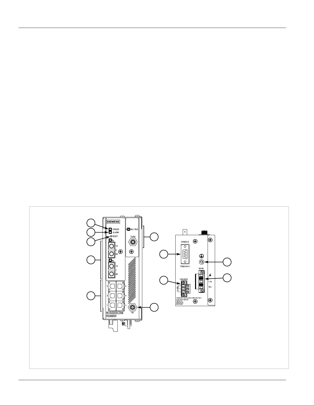
The RUGGEDCOM RS900W features various ports, controls and indicator LEDs on the front panel for connecting,
configuring and troubleshooting the device.
Figure1:RUGGEDCOM RS900W
1.POWER LED 2.ALARM LED 3.RESET Button 4.[Optional] Copper (10/100Base-TX) or Fiber Optic (100Base-FX) Ethernet Ports
5.Copper (10/100Base-TX) Ethernet Ports 6.Wireless Ethernet Ports 7.RS232 Console Port (Serial) 8.Failsafe Alarm Relay 9.Chassis
Ground Connection 10.Power Supply Terminal Block
2 Description
Page 13

RUGGEDCOM RS900W
Installation Guide
POWER LED Illuminates when power is supplied to the device.
ALARM LED Illuminates when an alarm condition exists.
Chapter 1
Introduction
RS232 Console Port The serial console port is for interfacing directly with the device and accessing initial
management functions. For information about connecting to the device via the serial
console port, refer to Section2.9, “Connecting to the Device”.
RESET Button Shuts down and restarts the device. For more information, refer to Section2.11, “Resetting
the Device”.
Communication Ports Receive and transmit data, as well as provide access to the RUGGEDCOM ROS Web interface.
For more information about the various ports available for the RUGGEDCOM RS900W, refer
to Chapter3, Communication Ports.
Failsafe Alarm Relay Latches to default state when a power disruption or other alarm condition occurs. For more
information, refer to:
• Section2.7, “Connecting the Failsafe Alarm Relay”
• Section4.2, “Failsafe Relay Specifications”
Power Supply Terminal Block A pluggable terminal block. For more information, refer to Section2.8, “Connecting Power”
and Section4.1, “Power Supply Specifications”.
Description 3
Page 14

Chapter 1
Introduction
RUGGEDCOM RS900W
Installation Guide
4 Description
Page 15

RUGGEDCOM RS900W
Installation Guide
Installing the Device
Installing the Device
The following sections describe how to install the device, including mounting the device, installing/removing
modules, connecting power, and connecting the device to the network.
DANGER!
Electrocution hazard – risk of serious personal injury and/or damage to equipment. Before performing
any maintenance tasks, make sure all power to the device has been disconnected and wait
approximately two minutes for any remaining energy to dissipate.
WARNING!
Radiation hazard – risk of serious personal injury. This product contains a laser system and is classified
as a Class I LASER PRODUCT. Use of controls or adjustments or performance of procedures other than
those specified herein may result in hazardous radiation exposure.
Chapter 2
IMPORTANT!
This product contains no user-serviceable parts. Attempted service by unauthorized personnel shall
render all warranties null and void.
Changes or modifications not expressly approved by Siemens Canada Ltd could invalidate
specifications, test results, and agency approvals, and void the user's authority to operate the
equipment.
IMPORTANT!
This product should be installed in a restricted access location where access can only be gained by
authorized personnel who have been informed of the restrictions and any precautions that must be
taken. Access must only be possible through the use of a tool, lock and key, or other means of security,
and controlled by the authority responsible for the location.
CONTENTS
• Section2.1, “General Procedure”
• Section2.2, “Required Tools and Materials”
• Section2.3, “Cabling Recommendations”
• Section2.4, “Installing the Device in Hazardous Locations”
• Section2.5, “Mounting the Device”
• Section2.6, “Connecting the Antennas”
• Section2.7, “Connecting the Failsafe Alarm Relay”
• Section2.8, “Connecting Power”
• Section2.9, “Connecting to the Device”
• Section2.10, “Configuring the Device”
• Section2.11, “Resetting the Device”
5
Page 16

Chapter 2
Installing the Device
Section2.1
RUGGEDCOM RS900W
Installation Guide
General Procedure
The general procedure for installing the device is as follows:
1. Review the relevant certification information for any regulatory requirements. For more information, refer to
Section6.1, “Approvals”.
2. Mount the device.
3. Install and connect the antennas.
4. Connect the failsafe alarm relay.
5. Connect power to the device and ground the device to safety Earth.
6. Connect the device to the network.
7. Configure the device.
Section2.2
Required Tools and Materials
The following tools and materials are required to install the RUGGEDCOM RS900W:
Tools/Materials Purpose
AC power cord (16 AWG) For connecting power to the device.
CAT-5 Ethernet cables For connecting the device to the network.
Flathead screwdriver For mounting the device to a DIN rail.
Phillips screwdriver For mounting the device to a panel.
4 x #6-32 screws For mounting the device to a panel.
Section2.3
Cabling Recommendations
All copper Ethernet ports on RUGGEDCOM products include transient suppression circuitry to protect against
damage from electrical transients and conform with IEC 61850-3 and IEEE 1613 Class I standards. This means that
during a transient electrical event, communications errors or interruptions may occur, but recovery is automatic.
Siemens also does not recommend using copper Ethernet ports to interface with devices in the field across
distances that could produce high levels of ground potential rise (i.e. greater than 2500 V), during line-to-ground
fault conditions.
6 General Procedure
Page 17

RUGGEDCOM RS900W
Installation Guide
Section2.4
Installing the Device
Installing the Device in Hazardous Locations
The RUGGEDCOM RS900W is designed to comply with the safety standards for Class I, Division 2 hazardous
locations where concentrations of flammable gases, vapors or liquids may be present, as opposed to normal
operating environments.
IMPORTANT!
The device is certified for installation in hazardous environments as a component only. It is required
to be installed in a suitable enclosure where the final combination is subject to acceptance by an
authorized local inspection authority.
Installation and use of the device in a hazardous location should meet the following special conditions for safe
use:
• The equipment should be installed in an enclosure that is considered to be not accessible in normal operation
without the use of a tool providing a degree of protection of not less than IP54. The enclosure should have a
minimum service temperature range of -40 to 100 °C (-40 to 212 °F).
• The equipment should be used in an area of not more than pollution degree 2.
• The console port should only be used in the safe area.
• The equipment should be appropriately connected to safety Earth upon installation.
Chapter 2
NOTE
For further details of the device's compliance with Class I, Division 2 standards, refer to Section6.1,
“Approvals”.
IMPORTANT!
Do not disconnect or open equipment unless power has been switched off or the area is known to be
non-hazardous.
IMPORTANT !
Débrancher ou ouvrir l'équipment seulement si l'alimnetation a été coupée ou si l'on sait que la zone
ne pose aucun danger.
IMPORTANT!
Substitution of the components may impair suitability for Class I, Division 2.
IMPORTANT !
Le remplacement de composants pourrait compromettre l'admissibilité à la Classe I, Division 2.
Section2.5
Mounting the Device
The RUGGEDCOM RS900W is designed for maximum mounting and display flexibility. It can be equipped with
adapters that allow it to be installed on a 35 mm (1.4 in) DIN rail or affixed to a panel.
IMPORTANT!
Heat generated by the device is channeled outwards to the enclosure. As such, it is recommended that
2.5 cm (1 in) of space be maintained on all open sides of the device to allow for some convectional
airflow.
Installing the Device in Hazardous Locations 7
Page 18

Chapter 2
1
1
2
Installing the Device
Forced airflow is not required. However, any increase in airflow will result in a reduction of ambient
temperature and improve the long-term reliability of all equipment mounted in the rack space.
NOTE
For detailed dimensions of the device with either DIN rail or panel hardware installed, refer to
Chapter5, Dimension Drawings.
CONTENTS
• Section2.5.1, “Mounting the Device on a DIN Rail”
• Section2.5.2, “Mounting the Device to a Panel”
Section2.5.1
Mounting the Device on a DIN Rail
For DIN rail installations, the RS900W can be equipped with a DIN rail bracket pre-installed on the back of the
chassis. The bracket allows the device to be slid onto a standard 35 mm (1.4 in) DIN rail.
To mount the device to a DIN rail, do the following:
1. Align the slot in the bracket with the DIN rail.
RUGGEDCOM RS900W
Installation Guide
Figure2:DIN Rail Mounting
1.DIN Rail 2.DIN Rail Bracket
2. Pull the release on the bracket down and slide the device onto the DIN rail. Let go of the release to lock the
device in position. If access to the release is limited, use a slotted screwdriver or a similar tool to reach the
release.
8 Mounting the Device on a DIN Rail
Page 19

RUGGEDCOM RS900W
2
1
2
1
Installation Guide
Section2.5.2
Installing the Device
Mounting the Device to a Panel
For panel installations, the RUGGEDCOM RS900W can be equipped with panel adapters pre-installed on the top
and bottom of the chassis. The adapters allow the device to be attached to a panel using screws.
To mount the device to a panel, do the following:
1. Prepare mounting holes in the panel where the device is to be installed.
2. Place the device against the panel and align the adapters with the mounting holes.
Chapter 2
Figure3:Panel Mounting
1.Panel Mount Adapter 2.Screw
3. Secure the adapters to the panel with #6-32 screws.
Section2.6
Connecting the Antennas
The RUGGEDCOM RS900W supports two dipole antennas that can be rotated 360° around the connection point,
and up to 90° at the joint for optimal positioning.
NOTE
The RUGGEDCOM RS900W is shipped with two 2.4 GHz dipole antennas.
Mounting the Device to a Panel 9
Page 20

Chapter 2
Installing the Device
Installation Guide
NOTE
For technical specifications, refer to Section3.3, “Wireless Ethernet Ports”.
To connect the antennas, do the following:
1. Make sure the operating frequency range of each antenna is compatible with the device.
2. Align the antenna connector with the wireless port (either TX/RX or RX) and thread the antenna onto the
port. Make sure the connection is finger tight.
RUGGEDCOM RS900W
Figure4:Antenna Installation
3. Repeat Step 2 for the second antenna.
4. Adjust the position of each antenna as needed.
Section2.7
Connecting the Failsafe Alarm Relay
The failsafe relay can be configured to latch based on alarm conditions. The NO (Normally Open) contact is closed
when the unit is powered and there are no active alarms. If the device is not powered or if an active alarm is
configured, the relay opens the NO contact and closes the NC (Normally Closed) contact.
NOTE
Control of the failsafe relay output is configurable through ROS. One common application for this relay
is to signal an alarm if a power failure occurs. For more information, refer to the ROS User Guide for
the RUGGEDCOM RS900W.
The following shows the proper relay connections.
10 Connecting the Failsafe Alarm Relay
Page 21

RUGGEDCOM RS900W
1 2 3
Installation Guide
Figure5:Failsafe Alarm Relay Wiring
1.Normally Closed 2.Common 3.Normally Open
Section2.8
Connecting Power
Installing the Device
Chapter 2
The RUGGEDCOM RS900W supports power input from a single high AC/DC or low DC power supply.
IMPORTANT!
• For 110/230 VAC rated equipment, an appropriately rated AC circuit breaker must be installed.
• For 125/250 VDC rated equipment, an appropriately rated DC circuit breaker must be installed.
• Use only #16 gage copper wiring when connecting terminal blocks.
• Equipment must be installed according to applicable local wiring codes and standards.
• All line-to-ground transient energy is shunted to the Surge Ground terminal. In cases where users
require the inputs to be isolated from ground, remove the ground braid between Surge and Chassis
Ground. Note that all line-to-ground transient protection circuitry will be disabled.
CONTENTS
• Section2.8.1, “Connecting High AC/DC Power”
• Section2.8.2, “Connecting Low DC Power”
Section2.8.1
Connecting High AC/DC Power
To connect a high AC/DC power supply to the device, do the following:
CAUTION!
Electrical hazard – risk of damage to equipment. Do not connect AC power cables to terminals for DC
Connecting Power 11
power. Damage to the power supply may occur.
Page 22

Chapter 2
4
1 2 3
Installing the Device
CAUTION!
Electrical hazard – risk of damage to equipment. Before testing the dielectric strength (HIPOT) in the
field, remove the braided ground cable connected to the surge ground terminal and chassis ground.
This cable connects transient suppression circuitry to chassis ground and must be removed in order to
avoid damage to transient suppression circuitry during testing.
NOTE
Torque all terminal connections to 0.6 N·m (5 lbf-in).
1. Connect the positive wire from the power source to the positive/live (+/L) terminal on the terminal block.
RUGGEDCOM RS900W
Installation Guide
Figure6:Terminal Block Wiring
1.Positive/Live (+/L) Terminal 2.Negative/Neutral (-/N) Terminal 3.Surge Ground Terminal 4.Braided Ground Cable
2. Connect the negative wire from the power source to the negative/neutral (-/N) terminal on the terminal block.
3. Using a braided wire or other appropriate grounding wire, connect the surge ground terminal to the chassis
ground connection. The surge ground terminal is used as the ground conductor for all surge and transient
suppression circuitry internal to the unit.
4. Connect the ground terminal on the power source to the chassis ground terminal on the device.
12 Connecting High AC/DC Power
Page 23

RUGGEDCOM RS900W
1 3
2
4
±
±
Installation Guide
Section2.8.2
Installing the Device
Connecting Low DC Power
RUGGEDCOM RS900W's equipped with 24 or 48 V power supply inputs feature reverse polarity protection and dual
power supply inputs allowing the device to accept redundant connections to a single DC power supply.
To connect a low DC power supply to the device, do the following:
NOTE
Torque all terminal connections to 0.6 N·m (5 lbf-in).
1. Connect the positive wire from the power source to the positive terminal on the terminal block.
Chapter 2
Figure7:Terminal Block Wiring - Single DC Power Supply Inputs
1.Positive Terminal 2.Negative Terminal 3.Surge Ground Terminal 4.Braided Ground Cable
2. Connect the negative wire from the power source to the negative terminal on the terminal block.
3. [Optional] If a redundant connection is required, repeat steps Step 1 and Step 2 to connect the secondary
power inputs.
Connecting Low DC Power 13
Page 24

Chapter 2
±
±
±
±
1 3 1
2 2
4
Installing the Device
RUGGEDCOM RS900W
Installation Guide
Figure8:Terminal Block Wiring - Dual DC Power Supply Inputs
1.Positive Terminal 2.Negative Terminal 3.Surge Ground Terminal 4.Braided Ground Cable
4. Using a braided wire or other appropriate grounding wire, connect the surge ground terminal to the chassis
ground connection. The surge ground terminal is used as the ground conductor for all surge and transient
suppression circuitry internal to the unit.
5. Connect the ground terminal on the power source to the chassis ground terminal on the device.
Section2.9
Connecting to the Device
The following describes the various methods for accessing the RUGGEDCOM ROS console and Web interfaces
on the device. For more detailed instructions, refer to the RUGGEDCOM ROS User Guide for the RUGGEDCOM
RS900W.
IMPORTANT!
Ethernet cables should be only be connected/disconnected in a non-hazardous area, or when the
device is not energized.
RS232 Console Port
Connect a workstation directly to the RS232 serial console port to access the boot-time control and RUGGEDCOM
ROS console interface.
14 Connecting to the Device
Page 25

RUGGEDCOM RS900W
1
5
9
6
Installation Guide
IMPORTANT!
The serial console port is intended to be used only as a temporary connection during initial
configuration or troubleshooting, and should only be used in a safe area (as defined by IEC 60079-0,
Edition 6.0).
Use the following settings to connect to either port:
Speed 57600 Mbps
Data Bits 8
Stop Bit 1
Parity None
Flow Control Off
Terminal ID VT100
Speed 57600 Mbps
The serial console port implements RS232 DCE (Data Communication Equipment) on a DB9 connector. The
following is the pin-out for the port:
Pin Name Description
a
1
Reserved (Do Not Connect)
Installing the Device
Chapter 2
2 TX Transmit Data
3 RX Receive Data
a
Figure9:Serial DB9 Console Port
a
Connected internally.
b
Connected internally.
4
5 GND Signal Ground
a
6
b
7
b
8
9 Reserved (Do Not Connect)
Reserved (Do Not Connect)
Reserved (Do Not Connect)
Reserved (Do Not Connect)
Reserved (Do Not Connect)
Communication Ports
Connect any of the available Ethernet ports on the device to a management switch and access the RUGGEDCOM
ROS console and Web interfaces via the device's IP address. The factory default IP address for the RUGGEDCOM
RS900W is https://192.168.0.1.
For more information about available ports, refer to Chapter3, Communication Ports.
Connecting to the Device 15
Page 26

Chapter 2
Installing the Device
Section2.10
RUGGEDCOM RS900W
Installation Guide
Configuring the Device
Once the device is installed and connected to the network, it must be configured. All configuration management
is done via the RUGGEDCOM ROS interface. For more information about configuring the device, refer to the
RUGGEDCOM ROS User Guide associated with the installed software release.
Section2.11
Resetting the Device
The RUGGEDCOM RS900W can be reset (rebooted) using the RESET button. The RESET button is recessed and can
only be reached using a pin or small screwdriver.
To reset the device, quickly press and release the RESET button with a pin.
16 Configuring the Device
Page 27

RUGGEDCOM RS900W
2
1
3
3
Installation Guide
Communication Ports
Communication Ports
The RUGGEDCOM RS900W can be equipped with various types of communication ports to enhance its abilities and
performance.
Chapter 3
Figure10:Port Assignment
1.Ports 1 to 6 2.Ports 7 and 8 3.Port 9
Port Type
1 to 6 Copper Ethernet Ports (10/100Base-TX)
7 and 8 Copper (10/100Base-TX) or Fiber Optic (10/100Base-FX) Ethernet Ports
9 Wireless Antennas
CONTENTS
• Section3.1, “Copper Ethernet Ports”
• Section3.2, “Fiber Optic Ethernet Ports”
• Section3.3, “Wireless Ethernet Ports”
17
Page 28

Chapter 3
1
2
1
8
Communication Ports
Section3.1
Installation Guide
Copper Ethernet Ports
The RUGGEDCOM RS900W supports multiple 10/100Base-TX Ethernet ports that allow connection to standard
Category 5 (CAT-5) unshielded twisted-pair (UTP) cables with RJ45 male connectors. The RJ45 receptacles are
directly connected to the chassis ground on the device and can accept CAT-5 shielded twisted-pair (STP) cables.
WARNING!
Electric shock hazard – risk of serious personal injury and/or equipment interference. If shielded
cables are used, make sure the shielded cables do not form a ground loop via the shield wire and the
RJ45 receptacles at either end. Ground loops can cause excessive noise and interference, but more
importantly, create a potential shock hazard that can result in serious injury.
LEDs
Each port features a Speed and Link/Activity LED that indicates the state of the port.
LED State Description
RUGGEDCOM RS900W
Figure11:RJ45 Port LEDs
1.Speed LED 2.Link/Activity LED
Pin-Out
The following is the pin-out for the RJ45 male connectors:
Figure12:RJ45 Ethernet Port Pin Configuration
Speed
Link/Activity
Pin Name Description
1 RX+ Receive Data+
2 RX- Receive Data-
3 TX+ Transmit Data+
4 Reserved (Do Not Connect)
5 Reserved (Do Not Connect)
6 TX- Transmit Data-
Yellow The port is operating
Off The port is operating
Yellow (Solid) Link established
Yellow (Blinking) Link activity
Off No link detected
at 100 Mbps
at 10 Mbps
7 Reserved (Do Not Connect)
8 Reserved (Do Not Connect)
Specifications
For specifications on the available copper Ethernet ports, refer to Section4.3, “Copper Ethernet Port
Specifications”.
18 Copper Ethernet Ports
Page 29

RUGGEDCOM RS900W
21
21
21
21
Installation Guide
Section3.2
Communication Ports
Fiber Optic Ethernet Ports
Fiber optic Ethernet ports are available with either MTRJ (Mechanical Transfer Registered Jack), LC (Lucent
Connector), SC (Standard or Subscriber Connector) or ST (Straight Tip) connectors. Make sure the Transmit (Tx)
and Receive (Rx) connections of each port are properly connected and matched to establish a proper link.
Port Types
Chapter 3
Figure13:MTRJ Port
1.Tx Connector 2.Rx Connector
Figure15:SC Port
1.Tx Connector 2.Rx Connector
Figure14:LC Port
1.Tx Connector 2.Rx Connector
Figure16:ST Port
1.Tx Connector 2.Rx Connector
LEDs
Each port features an LED that indicates the link/activity state of the port.
State Description
Yellow (Solid) Link established
Yellow (Blinking) Link activity
Off No link detected
Specifications
For specifications on the available fiber optic Ethernet ports, refer to Section4.4, “Fiber Optic Ethernet Port
Specifications”.
Fiber Optic Ethernet Ports 19
Page 30

Chapter 3
Communication Ports
Section3.3
RUGGEDCOM RS900W
Installation Guide
Wireless Ethernet Ports
The RUGGEDCOM RS900W supports an optional set of IEEE 802.11 compliant wireless Ethernet ports for accessing
a Wireless Local Area Network (WLAN). Depending on the options chosen, the device is permitted for use in either
North America (US), the European Union (EU), Australia (AU), or India (IN).
CONTENTS
• Section3.3.1, “Supported Wireless Standards”
• Section3.3.2, “Radio Characteristics”
• Section3.3.3, “Channel Allocations for IEEE 802.11b/g”
Section3.3.1
Supported Wireless Standards
Standard Parameter Mode Notes
IEEE 802.11g 54 Mbps (WLAN) Full Access Point 2.4 GHz ISM
IEEE 802.11b 11 Mbps (WLAN) Client support Backwards compatibility
Strong Encryption WPA2-AES (CCMP) Robust Secure Network (RSN)
Enhanced Encryption WPA-TKIP (RC4) Temporal keysIEEE 802.11i
Basic Encryption WEP (RC4) Up to 4 static keys
IEEE 802.1x Wireless Authentication Personal or Enterprise PSK or RADIUS
Section3.3.2
Radio Characteristics
Modulation Direct Sequence Spread Spectrum 802.11b/OFDM 802.11g
Frequency Range 2.4 Ghz to 2.4965 Ghz
Data Rate 6-54 Mbps: OFDM
11 Mbps: CCK
5.5 Mbps: CCK
2 Mbps: DQPSK
1 Mbps: DBPSK
Channels 11 - US (FCC)
11 - CAN (IC)
14 - Japan (MKK)
13 - Other countries (ETS)
Output Power 100 mW (20 dBm) 802.11b 11 Mbps Data Rate
100 mW (20 dBm) 802.11g 6-24 Mbps Data Rate
79 mW (19 dBm) 802.11g 36 Mbps Data Rate
20 Wireless Ethernet Ports
Page 31

RUGGEDCOM RS900W
Installation Guide
63 mW (18 dBm) 802.11g 48 Mbps Data Rate
40 mW (16 dBm) 802.11g 54 Mbps Data Rate
Receiver Sensitivity At Radio 802.11b 11 Mb @ -88 dBm/With Antenna: 11 Mb @ -91 dBm
At Radio 802.11g 54 Mb @ -74 dBm/With Antenna: 54 Mb @ -77 dBm
Communication Ports
Section3.3.3
Channel Allocations for IEEE 802.11b/g
The following details the channel identifiers, channel center frequencies and regulatory domains of each IEEE
802.11b/g 22-MHz-wide channel:
NOTE
Mexico is included in the Rest of World regulatory domain. However, channels 1 through 8 are for
indoor use only while channels 9 through 11 can be used indoors and outdoors. Users are responsible
for making sure the channel set configuration complies with the regulatory standards of Mexico.
Chapter 3
Channel Identifier Frequency(MHz)
1 2412 ● ● ● ●
2 2417 ● ● ● ●
3 2422 ● ● ● ●
4 2427 ● ● ● ●
5 2432 ● ● ● ●
6 2437 ● ● ● ●
7 2442 ● ● ● ●
8 2447 ● ● ● ●
9 2452 ● ● ● ●
10 2457 ● ● ● ●
11 2462 ● ● ● ●
12 2467 ● ● ●
13 2472 ● ● ●
a
14
a
Not supported in Japan for 802.11g mode.
2484 ●
Regulatory Domains
America (-A) EMEA (-E) Japan (-J) Rest of World (-W)
Channel Allocations for IEEE 802.11b/g 21
Page 32

Chapter 3
Communication Ports
RUGGEDCOM RS900W
Installation Guide
22 Channel Allocations for IEEE 802.11b/g
Page 33

RUGGEDCOM RS900W
Installation Guide
Technical Specifications
This section provides important technical specifications related to the device.
CONTENTS
• Section4.1, “Power Supply Specifications”
• Section4.2, “Failsafe Relay Specifications”
• Section4.3, “Copper Ethernet Port Specifications”
• Section4.4, “Fiber Optic Ethernet Port Specifications”
• Section4.5, “Operating Environment”
• Section4.6, “Mechanical Specifications”
Technical Specifications
Chapter 4
Section4.1
Power Supply Specifications
Hazardous Environments
Power Supply Type
HI
24 12 VDC 24 VDC 3.15 A(T) 1.5 kVDC 10 W
48 37 VDC 72 VDC 3.15 A(T) 1.5 kVDC 10 W
a
(T) denotes time-delay fuse.
b
Power consumption varies based on configuration.
Minimum Maximum
125 VDC 250 VDC 3.15 A(T) 4 kVAC 10 W
100 VAC 240 VAC 3.15 A(T) 4 kVAC 10 W
Non-Hazardous Environments
Power Supply Type
Minimum Maximum
Input Range
Input Range
Internal
Fuse Rating
Internal
Fuse Rating
a
c
Isolation
Isolation
Maximum Power
Consumption
Maximum Power
Consumption
b
d
HI
24 10 VDC 36 VDC 3.15 A(T) 1.5 kVDC 10 W
88 VDC 300 VDC 3.15 A(T) 4 kVAC 10 W
85 VAC 264 VAC 3.15 A(T) 5.5 kVDC 10 W
Power Supply Specifications 23
Page 34

Chapter 4
Technical Specifications
RUGGEDCOM RS900W
Installation Guide
Power Supply Type
48 37 VDC 72 VDC 3.15 A(T) 1.5 kVDC 10 W
c
(T) denotes time-delay fuse.
d
Power consumption varies based on configuration.
Minimum Maximum
Input Range
Section4.2
Failsafe Relay Specifications
Hazardous Environments
Maximum Switching Voltage Rated Switching Current Isolation
30 VDC 1 A
80 VDC
30 VAC
Non-Hazardous Environments
0.3 A
Internal
Fuse Rating
c
Isolation
1500 V
Maximum Power
for 1 minute
rms
Consumption
d
Maximum Switching Voltage Rated Switching Current Isolation
30 VDC 2 A, 60 W
125 VDC 0.24 A, 30 W
125 VAC 0.5 A, 62.5 W
220 VDC 0.24 A, 60 W
250 VAC 0.25 A, 62.5 W
1500 V
for 1 minute
rms
Section4.3
Copper Ethernet Port Specifications
The following details the specifications for copper Ethernet ports that can be ordered with the RUGGEDCOM
RS900W.
e
Speed
Connector RJ45
e
Duplex
Cable Type
Wiring Standard
Maximum Distance
f
g
h
10/100Base-TX
FDX/HDX
> CAT 5
TIA/EIA T568A/B
100 m (328 ft)
24 Failsafe Relay Specifications
Page 35

RUGGEDCOM RS900W
Installation Guide
Technical Specifications
Chapter 4
Isolation
e
Auto-negotiating.
f
Shielded or unshielded.
g
Auto-crossover and auto-polarity.
h
Typical distance. Dependent on the number of connectors and splices.
i
RMS 1 minute.
i
1.5 kV
Section4.4
Fiber Optic Ethernet Port Specifications
The following details the specifications for fiber Ethernet ports that can be ordered with the RUGGEDCOM
RS900W.
NOTE
• All optical power numbers are listed as dBm averages. To convert from average to peak add 3 dBm.
To convert from peak to average, subtract 3 dBm.
• Maximum segment length is greatly dependent on factors such as fiber quality, and the number
of patches and splices. Consult a Siemens sales associate when determining maximum segment
distances.
Mode
MM ST
MM SC
MM MTRJ 62.5/125 1300 -19 -14 -31 -14 2 12
SM ST 9/125 1300 -15 -8 -32 -3 20 17
SM SC 9/125 1300 -15 -8 -31 -7 20 16
SM LC 9/125 1300 -15 -8 -34 -7 20 19
SM SC 9/125 1300 -5 0 -34 -3 50 29
SM LC 9/125 1300 -5 0 -35 3 50 30
SM SC 9/125 1300 0 5 -37 0 90 37
SM LC 9/125 1300 0 5 -37 0 90 37
MM LC 50/125 1300 -22.5 -14 -31 -14 2 8.5
j
Typical.
Connector
Type
Tx λ (nm)
62.5/125 1300 -19 -14 -31 -14 2 12
50/125 1300 -22.5 -14 -31 -14 2 8.5
62.5/125 1300 -19 -14 -31 -14 2 12
50/125 1300 -22.5 -14 -31 -14 2 8.5
j
Cable
Type (μm)
Tx (dBm)
Minimum Maximum
Rx
Sensitivity
(dBm)
Rx
Saturation
(dBm)
Distance
j
(km)
Power
Budget
(dB)
Fiber Optic Ethernet Port Specifications 25
Page 36

Chapter 4
Technical Specifications
Section4.5
Operating Environment
Parameter Range Comments
RUGGEDCOM RS900W
Installation Guide
Ambient Operating Temperature -40 to 85 °C
(-40 to 185 °F)
Ambient Relative Humidity 5% to 95% Non-condensing
Ambient Storage Temperature -40 to 85 °C
(-40 to 185 °F)
Section4.6
Mechanical Specifications
Dimensions Refer to Chapter5, Dimension Drawings
Weight 1.2 kg (2.7 lbs)
Ingress Protection IP40 (1 mm or 0.04 in objects)
Enclosure 20 AWG Galvanized Steel
Measured from a 30 cm (12 in) radius surrounding the center of the
enclosure.
26 Operating Environment
Page 37

RUGGEDCOM RS900W
99.06
187.96
168.66
65.3
116.59
7.87
Installation Guide
Dimension Drawings
Dimension Drawings
Chapter 5
NOTE
All dimensions are in millimeters, unless otherwise stated.
Figure17:Overall Dimensions
27
Page 38

Chapter 5
13.64
101.6 11.2
78.74 120.65
194.06
83.20
183.90
134.1
Dimension Drawings
RUGGEDCOM RS900W
Installation Guide
Figure18:Panel and DIN Rail Mount Dimensions
28
Page 39

RUGGEDCOM RS900W
Installation Guide
Certification
The RUGGEDCOM RS900W device has been thoroughly tested to guarantee its conformance with recognized
standards and has received approval from recognized regulatory agencies.
CONTENTS
• Section6.1, “Approvals”
• Section6.2, “EMC and Environmental Type Tests”
Section6.1
Approvals
Chapter 6
Certification
This section details the standards to which the RUGGEDCOM RS900W complies.
CONTENTS
• Section6.1.1, “CSA”
• Section6.1.2, “FCC”
• Section6.1.3, “FDA/CDRH”
• Section6.1.4, “ISED”
• Section6.1.5, “RoHS”
• Section6.1.6, “Other Approvals”
Section6.1.1
CSA
This device meets the requirements of the following Canadian Standards Association (CSA) standards under
certificate 1550963:
• CAN/CSA-C22.2 No. 60950-1
Information Technology Equipment – Safety – Part 1: General Requirements (Bi-National Standard, with UL
60950-1)
• UL 60950-1
Information Technology Equipment – Safety Part 1: General Requirements
• CAN/CSA-C22.2 No. 0-M91
General Requirements - Canadian Electrical Code, Part II
• CAN/CSA-C22.2 No. 142-M1987
Process Control Equipment Industrial Products
Approvals 29
Page 40

Chapter 6
Certification
• CAN/CSA-C22.2 No. 213-16
Nonincendive Electrical Equipment for Use in Class I and II, Division 2 and Class III, Divisions 1 and 2 Hazardous
(Classified) Locations (Bi-National Standard with ANSI/ISA-12.12.01-2016)
• UL 916
Standard for Energy Management Equipment
• ANSI/ISA-12.12.01-2015
Non-Incendive Electrical Equipment for Use in Class I and II, Division 2 and Class III, Division 1 and 2 Hazardous
(Classified) Locations
It is specifically approved for use in hazardous locations defined as:
• Class I, Division 2, Groups A, B, C, D
• Temperature rating T6 at 40 °C and T4A at 85 °C
Section6.1.2
RUGGEDCOM RS900W
Installation Guide
FCC
This device has been tested and found to comply with the limits for a Class A digital device, pursuant to Part 15 of
the FCC Rules. These limits are designed to provide reasonable protection against harmful interference when the
equipment is operated in a commercial environment.
This device generates, uses and can radiate radio frequency energy and, if not installed and used in accordance
with the instruction manual, may cause harmful interference to radio communications. Operation of this
equipment in a residential area is likely to cause harmful interference in which case users will be required to
correct the interference at their own expense.
This device further complies with Part 15, sub-part C of the FCC rules and is approved under the ID VG5RW80G.
Section6.1.3
FDA/CDRH
This device meets the requirements of the following U.S. Food and Drug Administration (FDA) standard:
• Title 21 Code of Federal Regulations (CFR) – Chapter I – Sub-chapter J – Radiological Health
Section6.1.4
ISED
This device is declared by Siemens Canada Ltd to meet the requirements of the following ISED (Innovation Science
and Economic Development Canada) standard:
• CAN ICES-3 (A)/NMB-3 (A)
This device further complies with IC RSS-210 and is approved under the ID 4997A-VG5RW80G.
30 FCC
Page 41

RUGGEDCOM RS900W
Installation Guide
Section6.1.5
RoHS
This device is declared by Siemens Canada Ltd to meet the requirements of the following RoHS (Restriction of
Hazardous Substances) directives for the restricted use of certain hazardous substances in electrical and electronic
equipment:
• China RoHS 2
Administrative Measure on the Control of Pollution Caused by Electronic Information Products
A copy of the Material Declaration is available online at https://support.industry.siemens.com/cs/ww/en/
view/109738831.
Section6.1.6
Other Approvals
This device meets the requirements of the following additional standards:
• IEEE 1613
IEEE Standard Environmental and Testing Requirements for Communications Networking Devices in Electric
Power Substations
• IEC 61000-6-2
Electromagnetic Compatibility (EMC) – Part 6-2: Generic Standards – Immunity for Industrial Environments
• IEC 61850-3
Communication Networks and Systems in Substations – Part 3: General Requirements
Chapter 6
Certification
Section6.2
EMC and Environmental Type Tests
The RUGGEDCOM RS900W has passed the following Electromagnetic Compatibility (EMC) and environmental
tests.
EMC Type Tests
Test Description Test Levels Severity Levels
Enclosure Contact ± 8 kV 4IEC 61000-4-2 ESD
Enclosure Air ± 15 kV 4
IEC 61000-4-3 Radiated RFI Enclosure Ports 20 V/m x
IEC 61000-4-4 Burst (Fast Transient)
IEC 61000-4-5 Surge Signal Ports ± 4 kV Line-to-Ground
Signal Ports ± 4 kV @ 2.5 kHz x
DC Power Ports ± 4 kV 4
AC Power Ports ± 4 kV 4
Earth
Ground Ports
± 4 kV 4
± 2 kV
4
RoHS 31
Page 42

Chapter 6
Certification
RUGGEDCOM RS900W
Installation Guide
Test Description Test Levels Severity Levels
DC Power Ports ± 2 kV Line-to-Ground
± 1 kV Line-to-Line
AC Power Ports ± 4 kV Line-to-Ground
± 2 kV Line-to-Line
IEC 61000-4-6 Induced (Conducted) RFI
Signal Ports 10 V 3
DC Power Ports 10 V 3
AC Power Ports 10 V 3
Earth
10 V 3
Ground Ports
IEC 61000-4-8 Magnetic Field Enclosure Ports 40 A/m Continuous
1000 A/m for 1 s
IEC 61000-4-29 Voltage Dips and Interrupts DC Power Ports 30% for 0.1 s
60% for 0.1 s
100% for 0.05 s
IEC 61000-4-11 Voltage Dips and Interrupts AC Power Ports 100% for 5 Periods
100% for 50 Periods
IEC 61000-4-12 Damped Oscillatory
Signal Ports 2.5 kV Common Mode @ 1 MHz
1 kV Differential Mode @ 1 MHz
DC Power Ports 2.5 kV Common Mode @ 1 MHz
1 kV Differential Mode @ 1 MHz
3
4
3
3
AC Power Ports 2.5 kV Common Mode @ 1 MHz
1 kV Differential Mode @ 1 MHz
Signal Ports 30 V Continuous
300 V for 1 s
DC Power Ports 30 V Continuous
300 V for 1 s
IEC 61000-4-17 Ripple on DC Power Supply DC Power Ports 10% 3
IEC 60255-5
Dielectric Strength
Signal Ports 2 kV (Failsafe Relay Output)
DC Power Ports 1.5 kV
AC Power Ports 2 kV
HV Impulse
Signal Ports 5 kV (Failsafe Relay Output)
DC Power Ports 5 kV
AC Power Ports 5 kV
3
4IEC 61000-4-16 Mains Frequency Voltage
4
32 EMC and Environmental Type Tests
Page 43

RUGGEDCOM RS900W
Installation Guide
EMC Immunity Type Tests per IEEE 1613
NOTE
The RUGGEDCOM RS900W meets Class 2 requirements for an all-fiber configuration and Class 1
requirements for copper ports. Class 1 allows for temporary communication loss, while Class 2 requires
error-free and interrupted communications.
Description Test Levels
Enclosure Contact ± 8 kVESD
Radiated RFI Enclosure Ports 35 V/m
Chapter 6
Certification
Enclosure Air ± 15 kV
Fast Transient
Oscillatory
HV Impulse
Dielectric Strength
Environmental Type Tests
Test Description Test Levels Severity Levels
Signal Ports ± 4 kV @ 2.5 kHz
DC Power Ports ± 4 kV
AC Power Ports ± 4 kV
Earth Ground Ports ± 4 kV
Signal Ports 2.5 kV Common Mode @ 1 MHz
DC Power Ports 2.5 kV Common and Differential Mode @ 1 MHz
AC Power Ports 2.5 kV Common and Differential Mode @ 1 MHz
Signal Ports 5 kV (Failsafe Relay)
DC Power Ports 5 kV
AC Power Ports 5 kV
Signal Ports 2 kV (Failsafe Relay)
DC Power Ports 1.5 kV
AC Power Ports 2 kV
IEC 60068-2-1 Cold Temperature Test Ad -40 °C (-40 °F), 16 Hours
IEC 60068-2-2 Dry Heat Test Bd 85 °C (185 °F), 16 Hours
IEC 60068-2-30 Humidity (Damp
Heat, Cyclic)
IEC 60255-21-1 Vibration 2 g @ 10-150 Hz Class 2
IEC 60255-21-2 Shock 30 g @ 11 ms Class 2
Test Db 95% (Non-Condensing),
55 °C (131 °F), 6 Cycles
EMC and Environmental Type Tests 33
Page 44

Chapter 6
Certification
RUGGEDCOM RS900W
Installation Guide
34 EMC and Environmental Type Tests
 Loading...