

Page 1
Preface
RUGGEDCOM RMC20
Installation Guide
Introduction
Installing the Device
Communication Ports
Technical Specifications
Dimension Drawings
Certification
1
2
3
4
5
6
01/2017
RC1007-EN-05
Page 2

RUGGEDCOM RMC20
Installation Guide
Copyright © 2017 Siemens Canada Ltd
All rights reserved. Dissemination or reproduction of this document, or evaluation and communication of its contents, is not authorized
except where expressly permitted. Violations are liable for damages. All rights reserved, particularly for the purposes of patent application or
trademark registration.
This document contains proprietary information, which is protected by copyright. All rights are reserved. No part of this document may be
photocopied, reproduced or translated to another language without the prior written consent of Siemens Canada Ltd.
Disclaimer Of Liability
Siemens has verified the contents of this document against the hardware and/or software described. However, deviations between the product
and the documentation may exist.
Siemens shall not be liable for any errors or omissions contained herein or for consequential damages in connection with the furnishing,
performance, or use of this material.
The information given in this document is reviewed regularly and any necessary corrections will be included in subsequent editions. We
appreciate any suggested improvements. We reserve the right to make technical improvements without notice.
Registered Trademarks
RUGGEDCOM™ and ROS™ are trademarks of Siemens Canada Ltd.
Other designations in this manual might be trademarks whose use by third parties for their own purposes would infringe the rights of the
owner.
Security Information
Siemens provides products and solutions with industrial security functions that support the secure operation of plants, machines, equipment
and/or networks. They are important components in a holistic industrial security concept. With this in mind, Siemens' products and solutions
undergo continuous development. Siemens recommends strongly that you regularly check for product updates.
For the secure operation of Siemens products and solutions, it is necessary to take suitable preventive action (e.g. cell protection concept) and
integrate each component into a holistic, state-of-the-art industrial security concept. Third-party products that may be in use should also be
considered. For more information about industrial security, visit http://www.siemens.com/industrialsecurity .
To stay informed about product updates as they occur, sign up for a product-specific newsletter. For more information, visit http://
support.automation.siemens.com .
Warranty
Siemens warrants this product for a period of five (5) years from the date of purchase, conditional upon the return to factory for maintenance
during the warranty term. This product contains no user-serviceable parts. Attempted service by unauthorized personnel shall render all
warranties null and void. The warranties set forth in this article are exclusive and are in lieu of all other warranties, performance guarantees
and conditions whether written or oral, statutory, express or implied (including all warranties and conditions of merchantability and fitness for
a particular purpose, and all warranties and conditions arising from course of dealing or usage or trade). Correction of nonconformities in the
manner and for the period of time provided above shall constitute the Seller’s sole liability and the Customer’s exclusive remedy for defective
or nonconforming goods or services whether claims of the Customer are based in contract (including fundamental breach), in tort (including
negligence and strict liability) or otherwise.
For warranty details, visit www.siemens.com/ruggedcom or contact a Siemens customer service representative.
Contacting Siemens
Address
Siemens Canada Ltd
Industry Sector
300 Applewood Crescent
Concord, Ontario
Canada, L4K 5C7
Telephone
Toll-free: 1 888 264 0006
Tel: +1 905 856 5288
Fax: +1 905 856 1995
E-mail
ruggedcom.info.i-ia@siemens.com
Web
www.siemens.com/ruggedcom
ii
Page 3

RUGGEDCOM RMC20
Installation Guide
Table of Contents
Table of Contents
Preface ............................................................................................................. v
Alerts .................................................................................................................................................. v
Training .............................................................................................................................................. vi
Customer Support ............................................................................................................................... vi
Chapter 1
Introduction ..................................................................................................... 1
1.1Feature Highlights ........................................................................................................................ 1
1.2 Description ................................................................................................................................... 2
Chapter 2
Installing the Device ......................................................................................... 5
2.1Mounting the Device .................................................................................................................... 5
2.1.1Mounting the Device on a DIN Rail ...................................................................................... 6
2.1.2Mounting the Device to a Panel .......................................................................................... 7
2.2Connecting Power ........................................................................................................................ 7
2.2.1Connecting AC Power ......................................................................................................... 8
2.2.2Connecting DC Power ........................................................................................................ 9
2.3Setting the Operating Mode ........................................................................................................ 10
2.3.1Serial-to-Fiber Conversion: Point-to-Point ........................................................................... 11
2.3.2Serial Standard Conversion ............................................................................................... 13
2.3.3Serial-to-Fiber Conversion: Loop Topology .......................................................................... 13
Chapter 3
Communication Ports ...................................................................................... 15
3.1Fiber Optic Ports ......................................................................................................................... 15
3.2 Serial Terminal ............................................................................................................................ 16
3.2.1RS232 Data Ports ............................................................................................................. 16
3.2.2RS485/422 Data Ports ....................................................................................................... 17
Chapter 4
Technical Specifications .................................................................................. 19
4.1Power Supply Specifications ........................................................................................................ 19
4.2Fiber Optic Port Specifications ..................................................................................................... 19
4.3Operating Environment ............................................................................................................... 20
4.4Mechanical Specifications ............................................................................................................ 20
iii
Page 4

Table of Contents
Chapter 5
RUGGEDCOM RMC20
Installation Guide
Dimension Drawings ....................................................................................... 21
Chapter 6
Certification .................................................................................................... 23
6.1 Approvals ................................................................................................................................... 23
6.1.1 CSA ................................................................................................................................. 23
6.1.2European Union (EU) ....................................................................................................... 24
6.1.3 FCC ................................................................................................................................. 24
6.1.4 FDA/CDRH ........................................................................................................................ 24
6.1.5Industry Canada ............................................................................................................... 24
6.1.6Other Approvals ............................................................................................................... 25
6.2EMC and Environmental Type Tests .............................................................................................. 25
iv
Page 5
RUGGEDCOM RMC20
Installation Guide
Preface
This guide describes the RUGGEDCOM RMC20. It describes the major features of the device, installation,
commissioning and important technical specifications.
It is intended for use by network technical support personnel who are responsible for the installation,
commissioning and maintenance of the device. It is also recommended for use by network and system planners,
system programmers, and line technicians.
CONTENTS
• “ Alerts ”
• “Training”
• “Customer Support”
Preface
Alerts
The following types of alerts are used when necessary to highlight important information.
DANGER!
DANGER alerts describe imminently hazardous situations that, if not avoided, will result in death or
serious injury.
WARNING!
WARNING alerts describe hazardous situations that, if not avoided, may result in serious injury and/or
equipment damage.
CAUTION!
CAUTION alerts describe hazardous situations that, if not avoided, may result in equipment damage.
IMPORTANT!
IMPORTANT alerts provide important information that should be known before performing a procedure
or step, or using a feature.
NOTE
NOTE alerts provide additional information, such as facts, tips and details.
Alerts v
Page 6

Preface
RUGGEDCOM RMC20
Installation Guide
Training
Siemens offers a wide range of educational services ranging from in-house training of standard courses on
networking, Ethernet switches and routers, to on-site customized courses tailored to the customer's needs,
experience and application.
Siemens' Educational Services team thrives on providing our customers with the essential practical skills to make
sure users have the right knowledge and expertise to understand the various technologies associated with critical
communications network infrastructure technologies.
Siemens' unique mix of IT/Telecommunications expertise combined with domain knowledge in the utility,
transportation and industrial markets, allows Siemens to provide training specific to the customer's application.
For more information about training services and course availability, visit www.siemens.com/ruggedcom or
contact a Siemens Sales representative.
Customer Support
Customer support is available 24 hours, 7 days a week for all Siemens customers. For technical support or general
information, contact Siemens Customer Support through any of the following methods:
Online
Visit http://www.siemens.com/automation/support-request to submit a Support Request (SR) or check on the status of an
existing SR.
Telephone
Call a local hotline center to submit a Support Request (SR). To locate a local hotline center, visit http://
www.automation.siemens.com/mcms/aspa-db/en/automation-technology/Pages/default.aspx .
Mobile App
Install the Industry Online Support app by Siemens AG on any Android, Apple iOS or Windows mobile device and be able to:
• Access Siemens' extensive library of support documentation, including FAQs and manuals
• Submit SRs or check on the status of an existing SR
• Contact a local Siemens representative from Sales, Technical Support, Training, etc.
• Ask questions or share knowledge with fellow Siemens customers and the support community
vi Training
Page 7

RUGGEDCOM RMC20
Installation Guide
Introduction
The RUGGEDCOM RMC20 series of media converters are industrially hardened and specifically designed to operate
reliably in electrically harsh and climatically demanding environments.
The RUGGEDCOM RMC20 is a utility-grade, protocol-independent, serial-to-fiber and serial standards converter for
all your serial communication requirements. The RUGGEDCOM RMC20 allows RS485, RS422, or RS232 devices or
networks to communicate over secure, noise immune, optically isolated, fiber optic cabling at extended distances
as well convert RS232 to either RS485 or RS422 serial standards.
The RUGGEDCOM RMC20 was designed specifically to provide years of maintenance free operation for all your
mission-critical, real-time control applications. To provide the utmost in reliability, the RUGGEDCOM RMC20
is tested to the most stringent international EMI and environmental standards for use in HV/MV electric utility
substations and industrial manufacturing, process and control and intelligent transportation systems applications.
All RUGGEDCOM products are packaged with a high reliability, built-in power supply (24V, 48V or HI voltage
options) and enclosed in a rugged galvanized steel enclosure suitable for panel or DIN-rail mounting.
Chapter 1
Introduction
CONTENTS
• Section1.1, “Feature Highlights”
• Section1.2, “Description”
Section1.1
Feature Highlights
Key Features
• Extend lengths of serial connections (up to 5 km or 3 mi per hop)
• Media conversation is transparent to end devices
Port Options
• Protocol independent RS485, RS422, or RS232 (user selectable) conversion to multi-mode fiber optics (ST
connector only)
• RS232 to RS485/422 conversion mode
• Fully EIA/TIA RS485, RS422, RS232 compliant communications
• Built-in, defeat-able, RS485/RS422 termination networks
• Point-to-point, or optical loop configurations
• Full or half duplex configurable
• Support for high-speed serial baud rates from 300 to 115200 baud
Designed for Harsh Environments
• Operates over a temperature range of -40 to 85 °C (-40 to 185 °F) without the use of fans for improved
reliability
Feature Highlights 1
Page 8
Chapter 1
87
1
4
5
2
3
6
Introduction
• 21 AWG galvanized steel enclosure suitable for DIN or panel mounting provide secure mechanical reliability
Simple Plug and Play Operation
• Simple, externally-accessible configuration
• Transmit and receive data LED indicators for quick and easy troubleshooting
• Fully integrated power supply connects directly to power source permanently for reliable maintenance-free
operation
Universal Power Supply Options
• 24VDC, 48VDC or HI (88-300VDC / 85 - 264VAC) options for worldwide operability
• Integrated high-reliability power supply eliminates the need for external power transformer
• Screw down terminal blocks ensure reliable maintenance-free connections
• All power supplies CSA/UL 60950 approved for 85 °C (185 °F) operation
Section1.2
Description
RUGGEDCOM RMC20
Installation Guide
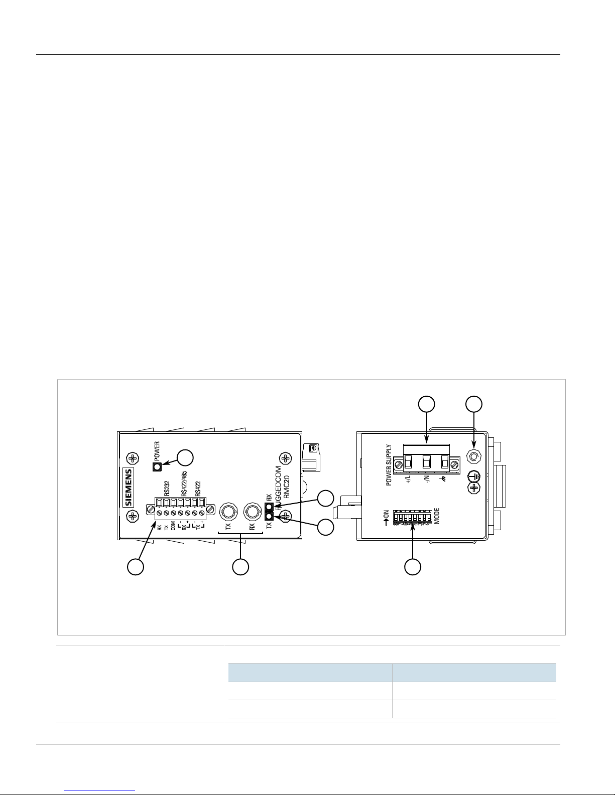
The RUGGEDCOM RMC20 features various ports, controls and indicator LEDs on the display panel for connecting,
configuring and troubleshooting the device. The display panel can be located on the rear, front or top of the
device, depending on the mounting configuration.
Figure1: RUGGEDCOM RMC20
1.POWER LED 2.Serial Terminal 3.Fiber Optic Ethernet Ports 4.TX LED 5.RX LED 6.MODE Switch 7.Power Terminal Block
8.Chassis Ground Terminal
POWER LED Illuminates when power is being supplied to the device.
2 Description
State Description
Green Power is on
Off Power is off
Page 9

RUGGEDCOM RMC20
Installation Guide
Serial Terminal The RS232/RS422/RS485 serial terminal serves a dual purpose:
• The RS232 terminals allow for a direct interface with the device and access to initial
management functions.
• The RS422/RS485 terminals allow for half or full duplex serial connections respectively. For
more information, refer to Chapter3, Communication Ports .
Power Supply Terminal A pluggable terminal. For more information, refer to:
• Section2.2, “Connecting Power”
• Section4.1, “Power Supply Specifications”
Chapter 1
Introduction
MODE Switch Sets the operating mode for the device. For more information, refer to Section2.3, “Setting
the Operating Mode” .
Communication Ports Receive and transmit data. For more information about the various ports available for the
RUGGEDCOM RMC20, refer to Chapter3, Communication Ports .
Description 3
Page 10

Chapter 1
Introduction
RUGGEDCOM RMC20
Installation Guide
4 Description
Page 11
RUGGEDCOM RMC20
Installation Guide
Installing the Device
Installing the Device
The following sections describe how to install the device, including mounting the device, installing/removing
modules, connecting power, and connecting the device to the network.
DANGER!
Electrocution hazard – risk of serious personal injury and/or damage to equipment. Before performing
any maintenance tasks, make sure all power to the device has been disconnected and wait
approximately two minutes for any remaining energy to dissipate.
WARNING!
Radiation hazard – risk of serious personal injury. This product contains a laser system and is classified
as a CLASS 1 LASER PRODUCT. Use of controls or adjustments or performance of procedures other
than those specified herein may result in hazardous radiation exposure.
Chapter 2
IMPORTANT!
This product contains no user-serviceable parts. Attempted service by unauthorized personnel shall
render all warranties null and void.
Changes or modifications not expressly approved by Siemens Canada Ltd could invalidate
specifications, test results, and agency approvals, and void the user's authority to operate the
equipment.
IMPORTANT!
This product should be installed in a restricted access location where access can only be gained by
authorized personnel who have been informed of the restrictions and any precautions that must be
taken. Access must only be possible through the use of a tool, lock and key, or other means of security,
and controlled by the authority responsible for the location.
CONTENTS
• Section2.1, “Mounting the Device”
• Section2.2, “Connecting Power”
• Section2.3, “Setting the Operating Mode”
Section2.1
Mounting the Device
The RUGGEDCOM RMC20 is designed for maximum mounting and display flexibility. It can be equipped with
connectors that allow it to be installed in a 35 mm (1.4 in) DIN rail or directly on a panel.
Mounting the Device 5
Page 12

Chapter 2
1
1
2
3
Installing the Device
IMPORTANT!
Heat generated by the device is channeled outwards to the enclosure. As such, it is recommended that
2.5 cm (1 in) of space be maintained on all open sides of the device to allow for some convectional
airflow.
Forced airflow is not required. However, any increase in airflow will result in a reduction of ambient
temperature and improve the long-term reliability of all equipment mounted in the rack space.
NOTE
For detailed dimensions of the device with either DIN rail or panel hardware installed, refer to
Chapter5, Dimension Drawings .
CONTENTS
• Section2.1.1, “Mounting the Device on a DIN Rail”
• Section2.1.2, “Mounting the Device to a Panel”
Section2.1.1
RUGGEDCOM RMC20
Installation Guide
Mounting the Device on a DIN Rail
For DIN rail installations, the RMC20 can be equipped with a DIN rail bracket pre-installed on the back of the
chassis. The bracket allows the device to be slid onto a standard 35 mm (1.4 in) DIN rail.
To mount the device to a DIN rail, do the following:
1. Align the slot in the bracket with the DIN rail.
Figure2:DIN Rail Mounting
1.DIN Rail 2.DIN Rail Bracket 3.Screw Driver
2. Pull the release on the bracket down and slide the device onto the DIN rail. If necessary, use a screw driver to
unlock the release. Let go of the release to lock the device in position.
6 Mounting the Device on a DIN Rail
Page 13

RUGGEDCOM RMC20
113
12
4
4
5
1
Installation Guide
Section2.1.2
Mounting the Device to a Panel
To mount the device to a panel, do the following:
1. Place the panel adapter against the panel and secure it with screws.
Installing the Device
Chapter 2
Figure3:Panel Mounting
1. RUGGEDCOM RMC20 2.Panel Adapter 3.Mounting Holes 4.Screw 5.Metal Clips
2. Insert the device into the adapter. Make sure the device is secured between the two metal clips.
Section2.2
Connecting Power
The RUGGEDCOM RMC20 supports a single integrated high AC/DC or low DC power supply
NOTE
• For 110/230 VAC rated equipment, an appropriately rated AC circuit breaker must be installed.
• For 125/250 VDC rated equipment, an appropriately rated DC circuit breaker must be installed.
• Use only #16 gage copper wiring when connecting terminal blocks.
• Equipment must be installed according to applicable local wiring codes and standards.
Mounting the Device to a Panel 7
Page 14

Chapter 2
Installing the Device
• All line-to-ground transient energy is shunted to the Surge Ground terminal. In cases where users
require the inputs to be isolated from ground, remove the ground braid between Surge and Chassis
Ground. Note that all line-to-ground transient protection circuitry will be disabled.
IMPORTANT!
Siemens requires the use of external surge protection in VDSL applications where the line may be
subject to surges greater than that for which the device is rated. Use the following specifications as a
guide for VDSL external surge protection:
• Clamping Voltage: 50 V to 200 V
• Insertion Loss: < 0.1 dB at 10 MHz
• Peak Surge Current: 10 kA, 8x20µs waveform
CONTENTS
• Section2.2.1, “Connecting AC Power”
• Section2.2.2, “Connecting DC Power”
Section2.2.1
RUGGEDCOM RMC20
Installation Guide
Connecting AC Power
To connect a high AC power supply to the device, do the following:
CAUTION!
Electrical hazard – risk of damage to equipment. Before testing the dielectric strength (HIPOT) in the
field, remove the braided ground cable connected to the surge ground terminal and chassis ground.
This cable connects transient suppression circuitry to chassis ground and must be removed in order to
avoid damage to transient suppression circuitry during testing.
1. Connect the positive wire from the power source to the positive/live (+/L) terminal on the terminal block.
8 Connecting AC Power
Page 15

RUGGEDCOM RMC20
1 2 3
4
Installation Guide
Installing the Device
Chapter 2
Figure4:Terminal Block Wiring
1.Positive/Live (+/L) Terminal 2.Negative/Neutral (-/N) Terminal 3.Surge Ground Terminal 4.Braided Ground Cable
2. Connect the negative wire from the power source to the negative/neutral (-/N) terminal on the terminal block.
3. Using a braided wire or other appropriate grounding wire, connect the surge ground terminal to the chassis
ground connection. The surge ground terminal is used as the ground conductor for all surge and transient
suppression circuitry internal to the unit.
4. Connect the ground terminal on the power source to the chassis ground terminal on the device.
Section2.2.2
Connecting DC Power
To connect a high or low DC power supply to the device, do the following:
CAUTION!
Electrical hazard – risk of damage to equipment. Before testing the dielectric strength (HIPOT) in the
field, remove the braided ground cable connected to the surge ground terminal and chassis ground.
This cable connects transient suppression circuitry to chassis ground and must be removed in order to
avoid damage to transient suppression circuitry during testing.
1. Connect the positive wire from the power source to the positive/live (+/L) terminal on the terminal block.
Connecting DC Power 9
Page 16

Chapter 2
1 2 3
4
Installing the Device
RUGGEDCOM RMC20
Installation Guide
Figure5:Terminal Block Wiring
1.Positive/Live (+/L) Terminal 2.Negative/Neutral (-/N) Terminal 3.Surge Ground Terminal 4.Braided Ground Cable
2. Connect the negative wire from the power source to the negative/neutral (-/N) terminal on the terminal block.
3. Using a braided wire or other appropriate grounding wire, connect the surge ground terminal to the chassis
ground connection. The surge ground terminal is used as the ground conductor for all surge and transient
suppression circuitry internal to the unit.
4. Connect the ground terminal on the power source to the chassis ground terminal on the device.
Section2.3
Setting the Operating Mode
To accommodate a wide array of serial devices, the RUGGEDCOM RMC20 is equipped with a MODE DIP switch
located on the bottom of the device. The switch configures the RUGGEDCOM RMC20 to accommodate different
serial partners that operate at various duplex modes and speeds. Choose the appropriate operating mode
according to the serial link partner.
10 Setting the Operating Mode
Page 17

RUGGEDCOM RMC20
1
Installation Guide
Figure6:MODE DIP Switch
1.MODE DIP Switch
The configuration settings are as follows:
Installing the Device
Chapter 2
Position ON OFF
1 RS232 to fiber mode RS485/422 to fiber mode
2 RS232 to RS485/422 conversion mode Serial (RS232/485/422) to fiber mode
3 Full Duplex Serial (RS232/RS422) Half Duplex Serial (RS485)
4 Fiber Repeat ON Fiber Repeat OFF
5 RESERVED
6 > 57600 baud
7 19200 – 57600 baud
8 4800 – 14400 baud
300 – 2400 baud
The RUGGEDCOM RMC20 is equipped to provide conversion from serial (RS232, RS485, or RS422) to fiber optics,
or between serial standards (RS232 to RS485 / RS422). Serial to fiber optic conversion connections can be further
implemented in point-to-point, as well as optical loop configurations.
CONTENTS
• Section2.3.1, “Serial-to-Fiber Conversion: Point-to-Point”
• Section2.3.2, “Serial Standard Conversion”
• Section2.3.3, “Serial-to-Fiber Conversion: Loop Topology”
Section2.3.1
Serial-to-Fiber Conversion: Point-to-Point
The following illustrates the serial-to-fiber conversion mode of operation.
Serial-to-Fiber Conversion: Point-to-Point 11
Page 18

Chapter 2
1 2
2 3
Installing the Device
NOTE
In this example, the distance between the two RUGGEDCOM RMC20 devices is less than 5 km (3.1 mi).
Figure7:Serial-to-Fiber Point-to-Point Topology
1.RS232 Device 2. RUGGEDCOM RMC20 3.RS485 Device/Network
RUGGEDCOM RMC20
Installation Guide
RS232 Device
Position State Notes
1 ON RS232 <-> Fiber
2 OFF Serial-to-Fiber Mode
3 ON Full Duplex
4 OFF Fiber repeat OFF
RS422 Device/Network
Position State Notes
1 OFF RS422 <-> Fiber
2 OFF Serial-to-Fiber Mode
3 ON Full Duplex
4 OFF Fiber repeat OFF
In this mode, serial data is converted directly into light impulses, and transmitted over multi-mode fiber optics.
The serial standard is selected by position 1 of the DIP switches: OFF (default) is for RS485/RS422, and ON is
for RS232. Position 2 should be OFF for serial to fiber conversion. Position 6-8 should be configured if RS485
communications are used, in order to have the appropriate turn-around timer shown below selected. Positions 6-8
do not impact communications in full-duplex mode.
NOTE
A baud rate lower than 1200 bps is not supported in half-duplex or RS485 mode.
Baud Rate (bps) DIP6 DIP7 DIP8 Turn-Around Time
1200-2400 OFF OFF OFF 9.5 ms
4800-14400 OFF OFF ON 2.3 ms
19200-57600 OFF ON OFF 0.58 ms
a
>57600 ON OFF OFF 0.10 ms
a
Turn-around time is the amount of time after the start bit was transmitted and before the transceiver changed back to receiver mode.
12 Serial-to-Fiber Conversion: Point-to-Point
Page 19

RUGGEDCOM RMC20
1 2 3
Installation Guide
Section2.3.2
Serial Standard Conversion
The following illustrates the connections for conversion between RS232 and RS485/422 devices.
Figure8:RS232 to RS485/422 Topology
1.RS232 Device 2. RUGGEDCOM RMC20 3.RS485 Device/Network
Installing the Device
Chapter 2
Position State Notes
2 ON Serial Conversion Mode
3 OFF Half Duplex
4 OFF Fiber repeat OFF
6 OFF
7 OFF
8 ON
9600 Baud
In this mode of operation, RS232 voltage levels are converted to the appropriate RS485 or RS422 signalling levels
depending on the DIP switch configuration. In this mode of operation position 2 of the DIP switches must be in
the ON position. The topology depicted in Figure 8 illustrates an RS232 device, connected to an RS485 device or
network. Since RS485 requires automatic turn-around, position 3 must be set to the OFF state, and position 6 – 8
of the DIP switches must reflect the proper operating baud rate.
NOTE
In this mode of operation, no isolation is provided between RS232 device and the RS485/422 network
– both devices share the same common terminal. It should be noted that the common terminal on
RS232 devices are connected to ground. In some instances (i.e. when connecting to large RS485
networks), it may be preferential for the user to leave the RS485/RS422 shield terminal unconnected to
the RUGGEDCOM RMC20 in this mode.
Section2.3.3
Serial-to-Fiber Conversion: Loop Topology
The following illustrates the optical loop topology that utilizes the RUGGEDCOM RMC20 repeat mode function.
Serial Standard Conversion 13
Page 20

Chapter 2
3
4
2
2
2
1
1
Installing the Device
RUGGEDCOM RMC20
Installation Guide
Figure9:Serial-to-Fiber Conversion in Example Optical Loop Topology
1.RS485 Slave (Repeat = ON) 2. RUGGEDCOM RMC20 3.Multiple RUGGEDCOM RMC20 Devices 4.RS485 Master (Repeat = OFF)
Position State Notes
1 OFF RS485/422 <-> Fiber
2 OFF Serial-to-Fiber Mode
3 OFF Half Duplex
4 OFF Fiber repeat: Refer to Figure 9
6 OFF
7 OFF
8 ON
9600 Baud
The repeat function will optically re-transmit any data received on the optical receiver, in addition to any
connected serial devices. As a result, any data transmitted from the master, will be re-transmitted optically to all
the slaves. This mode of operation requires that the master device tolerate receiving echoes of transmitted data
since any transmissions will be received once again via the optical ring.
This topology can be used for RS232, RS485 or RS422 multi-drop networks. In all cases, all slaves have the repeat
function (DIP position 4) ON, while the master is configured with the repeat function OFF. This topology can allow
for the mixture of RS232, RS485 and RS422 devices, operating on the same baud rate, on a single optical serial
network because the RUGGEDCOM RMC20 utilizes a common optical signalling protocol for all serial standards.
14 Serial-to-Fiber Conversion: Loop Topology
Page 21

RUGGEDCOM RMC20
2
1
Installation Guide
Communication Ports
Communication Ports
The RUGGEDCOM RMC20 can be equipped with various types of communication ports to enhance its abilities and
performance.
Chapter 3
Figure10:Port Assignment
1.Port 1 2.Port 2
Port Type
1 RS232/RS485/RS422 Serial Terminal
2 Multi-Mode Fiber Optic Port
CONTENTS
• Section3.1, “Fiber Optic Ports”
• Section3.2, “Serial Terminal”
Section3.1
Fiber Optic Ports
Fiber optic ports are available with ST (Straight Tip) connectors. Make sure the Transmit (Tx) and Receive (Rx)
connections of each port are properly connected and matched to establish a proper link.
Fiber Optic Ports 15
Page 22

Chapter 3
21
1 7
Communication Ports
Available Ports
Figure11:ST Port
1.Tx Connector 2.Rx Connector
Specifications
For specifications on the available fiber optic ports, refer to Section4.2, “Fiber Optic Port Specifications” .
Section3.2
Serial Terminal
RUGGEDCOM RMC20
Installation Guide
The RUGGEDCOM RMC20 is equipped with a seven-terminal Phoenix-style connector. This connector can
accommodate one RS232 connection, and one RS485/422 connection. The following is the pin-out for the serial
terminal:
Pin Name Mode Description
1 Rx RS232 Receive data
2 Tx RS232 Transmit data
3 COM Shared common
4 -Rx RS422/485 Receive data-
5 +Rx RS422/485 Receive data+
6 -Tx RS485 Transmit data-
Figure12:Serial Terminal Pin Configuration
7 +Tx RS485 Transmit data+
CONTENTS
• Section3.2.1, “RS232 Data Ports”
• Section3.2.2, “RS485/422 Data Ports”
Section3.2.1
RS232 Data Ports
The serial terminal includes a single EIA/TIA RS232 compliant port, consisting of three terminals: Transmit (Tx),
Receive (Rx) and Common (COM).
IMPORTANT!
The RS232 port is intended for point-to-point applications only.
16 Serial Terminal
Page 23

RUGGEDCOM RMC20
5
6
9
1
Installation Guide
Communication Ports
In adherence to the EIA/TIA guidelines for RS232 communications, the following is recommended by Siemens:
• Always use shielded cabling to minimize the effects of ambient electrical noise
• Although greater distances are possible, limit the cable length to 15 m (49 ft) or less for more reliable
communications
• Use a baud rate of 120 kbps
The RS232 port uses a Phoenix-style DB9 compression connector. The following is the pin-out for the connector:
Pin Name Description
1 Reserved (Do Not Connect)
2 RD Receive Data
3 TD Transmit Data
4 Reserved (Do Not Connect)
5 SGND Signal Ground
6 Reserved (Do Not Connect)
7 Reserved (Do Not Connect)
8 Reserved (Do Not Connect)
Chapter 3
9 Reserved (Do Not Connect)
Figure13:Phoenix-Style DB9 Connector Pin
Configuration
Section3.2.2
RS485/422 Data Ports
The serial terminal includes a single RS485/RS422 data port. In half duplex mode, the RS485 connections (Rx+,
Rx-, COM) should be connected. In full-duplex mode, the RS422 connections (Rx+, Rx-, Tx+, Tx-, COM) should
be connected. Both RS485 and RS422 can accommodate multi-drop networks, for master-slave serial network
communications. For both RS485/RS422 connections, the following general guidelines should be followed:
• To minimize the effects of ambient electrical noise, use shielded cabling.
• The correct polarity must be observed throughout a single sequence or ring.
• The number of devices wired should not exceed 32, and total distance should be less than 1219 m (4000 ft) at
100 kbps.
• The Common terminals should be connected to the common wire inside the shield.
• The shield should be connected to earth ground at a single point to avoid loop currents.
• The twisted pair should be terminated at each end of the chain (typically with a 120 Ohm resistor and a 10nF
capacitor in series across the twisted pair).
RS485/422 Data Ports 17
Page 24

Chapter 3
< 1219 m (4000 ft)
120Ω 10nF
1
2
3
5
5
6
4
Communication Ports
NOTE
The RUGGEDCOM RMC20 features built-in pull-up and pull-down resistors. As such, external bias
resistors are only recommended when connecting the RUGGEDCOM RMC20 to third-party serial devices
that do not have built-in pull-up and pull-down resistors.
NOTE
Transient protection is provided on all terminals. Lightning strikes and ground surge currents can cause
large momentary voltage differences between ends of communication links. For maximum reliability of
the entire link, all equipment should have similar transient protection installed.
The following shows the recommended RS485 wiring.
RUGGEDCOM RMC20
Installation Guide
Figure14:Recommended RS485 Wiring
1. RUGGEDCOM RMC20 Device With Built-In Termination 2.Common (Isolated Ground) 3.Negative 4.Positive 5.Shield to Earth
(Connected At a Single Point) 6.RS485 Devices (32 Total)
18 RS485/422 Data Ports
Page 25

RUGGEDCOM RMC20
Installation Guide
Technical Specifications
This section provides important technical specifications related to the device and available modules.
CONTENTS
• Section4.1, “Power Supply Specifications”
• Section4.2, “Fiber Optic Port Specifications”
• Section4.3, “Operating Environment”
• Section4.4, “Mechanical Specifications”
Section4.1
Technical Specifications
Chapter 4
Power Supply Specifications
Power Supply Type Minimum Input Maximum Input Internal Fuse Rating
24 VDC 18 VDC 36 VDC
48 VDC 36 VDC 59 VDC
b
HI
a
(T) denotes time-delay fuse.
b
This is the same power supply for both AC and DC.
Section4.2
a
3.15A (T) 3 W
88 VDC 300 VDC
85 VAC 264 VAC
Max. Power
Consumption
Fiber Optic Port Specifications
The following details the specifications for fiber optic ports that can be ordered with the RUGGEDCOM RMC20.
NOTE
• All optical power numbers are listed as dBm averages. To convert from average to peak add 3 dBm.
To convert from peak to average, subtract 3 dBm.
• Maximum segment length is greatly dependent on factors such as fiber quality, and the number
of patches and splices. Consult a Siemens Sales associate when determining maximum segment
distances.
Power Supply Specifications 19
Page 26

Chapter 4
Technical Specifications
RUGGEDCOM RMC20
Installation Guide
Mode
MM ST
c
Typical.
Connector
Type
Cable
Type (μm)
50/125
62.5/125
Tx λ (nm)
c
820 -13 -33.5 -11 5 17.5
Section4.3
Operating Environment
Parameter Range Comments
Ambient Operating Temperature -40 to 85 °C
Ambient Relative Humidity 5% to 95% Non-condensing
Ambient Storage Temperature -40 to 85 °C
Section4.4
(-40 to 185 °F)
(-40 to 185 °F)
Tx (dBm)RxSensitivity
(dBm)
Measured from a 30 cm (12 in) radius surrounding the center of the
enclosure.
Rx
Saturation
(dBm)
Distance
c
(km)
Power
Budget (dB)
Mechanical Specifications
Dimensions Refer to Chapter5, Dimension Drawings
Weight 0.68 kg (1.5 lbs)
Ingress Protection IP40 (1 mm or 0.04 in objects)
Enclosure 21 AWG Galvanized Steel
20 Operating Environment
Page 27

RUGGEDCOM RMC20
70.7
92.8
80.1
73.7
62.2
58.4
109.0
99.3
Installation Guide
Dimension Drawings
Dimension Drawings
Chapter 5
NOTE
All dimensions are in millimeters, unless otherwise stated.
Figure15:Overall Dimensions
21
Page 28

Chapter 5
121.7
113.8
105.7
57.2
4.0
11.4
35.6
58.4
62.2
67.3
109.0
96.1
82.2
Dimension Drawings
RUGGEDCOM RMC20
Installation Guide
Figure16:Panel Mount Dimensions
22
Page 29

RUGGEDCOM RMC20
Installation Guide
Certification
The RUGGEDCOM RMC20 device has been thoroughly tested to guarantee its conformance with recognized
standards and has received approval from recognized regulatory agencies.
CONTENTS
• Section6.1, “Approvals”
• Section6.2, “EMC and Environmental Type Tests”
Section6.1
Approvals
Chapter 6
Certification
This section details the approvals issued for the RUGGEDCOM RMC20.
CONTENTS
• Section6.1.1, “CSA”
• Section6.1.2, “European Union (EU)”
• Section6.1.3, “FCC”
• Section6.1.4, “FDA/CDRH”
• Section6.1.5, “Industry Canada”
• Section6.1.6, “Other Approvals”
Section6.1.1
CSA
This device is certified by the CSA Group to meet the requirements of the following standards:
• CSA-C22.2 NO. 60950-1
Information Technology Equipment – Safety – Part 1: General Requirements (Bi-National standard, with UL
60950-1)
• UL 60950-1
Information Technology Equipment – Safety – Part 1: General Requirements)
Approvals 23
Page 30

Chapter 6
Certification
Section6.1.2
RUGGEDCOM RMC20
Installation Guide
European Union (EU)
This device is declared by Siemens Canada Ltd to comply with essential requirements and other relevant provisions
of the following EU directives:
• EN 60950-1
Information Technology Equipment – Safety – Part 1: General Requirements
• EN 61000-6-2
Electromagnetic Compatibility (EMC) – Part 6-2: Generic Standards – Immunity for Industrial Environments
• EN 60825-1
Safety of Laser Products – Equipment Classification and Requirements
• EN 55022
Information Technology Equipment – Radio disturbance characteristics – Limits and methods of measurement
The device is marked with a CE marking and can be used throughout the European community.
A copy of the CE Declaration of Conformity is available from Siemens Canada Ltd. For contact information, refer to
“Contacting Siemens ” .
Section6.1.3
FCC
This equipment has been tested and found to comply with the limits for a Class A digital device pursuant to Part
15 of the FCC Rules. These limits are designed to provide reasonable protection against harmful interference when
the equipment is operated in a commercial environment.
This equipment generates, uses and can radiate radio frequency energy and, if not installed and used in
accordance with the instruction manual, may cause harmful interference to radio communications. Operation of
this equipment in a residential area is likely to cause harmful interference in which case the user will be required
to correct the interference on his own expense.
Section6.1.4
FDA/CDRH
This device meets the requirements of the following U.S. Food and Drug Administration (FDA) standard:
• Title 21 Code of Federal Regulations (CFR) – Chapter I – Sub-chapter J – Radiological Health
Section6.1.5
Industry Canada
This device is declared by Siemens Canada Ltd to meet the requirements of the following Industry Canada
standard:
24 European Union (EU)
Page 31

RUGGEDCOM RMC20
Installation Guide
• CAN ICES-3 (A)/NMB-3 (A)
Section6.1.6
Other Approvals
This device meets the requirements of the following additional standards:
• IEEE 1613
IEEE Standard Environmental and Testing Requirements for Communications Networking Devices in Electric
Power Substations
• IEC 61850-3
Communications Networks and Systems for Power Utility Automation – Part 3: General Requirements
Section6.2
EMC and Environmental Type Tests
The RUGGEDCOM RMC20 has passed the following EMC and environmental tests.
Chapter 6
Certification
IEC 61850-3 Type Tests
Test Description Test Levels Severity Levels
Enclosure Contact ± 8 kV 4IEC 61000-4-2 ESD
Enclosure Air ± 15 kV 4
IEC 61000-4-3 Radiated RFI Enclosure Ports 20 V/m Note
IEC 61000-4-4 Burst (Fast Transient)
IEC 61000-4-5 Surge
IEC 61000-4-6 Induced (Conducted) RFI
Signal Ports ± 4 kV @ 2.5 kHz Note
DC Power Ports ± 4 kV 4
AC Power Ports ± 4 kV 4
Earth
Ground Ports
Signal Ports ± 4 kV Line-to-Earth,
DC Power Ports ± 2 kV Line-to-Earth,
AC Power Ports ± 4 kV Line-to-Earth,
Signal Ports 10 V 3
DC Power Ports 10 V 3
± 4 kV 4
± 2 kV Line-to-Line
± 1 kV Line-to-Line
± 2 kV Line-to-Line
a
a
4
3
4
IEC 61000-4-8 Magnetic Field Enclosure Ports 40 A/m continuous, 1000 A/m for 1 s Note
Other Approvals 25
AC Power Ports 10 V 3
Earth
Ground Ports
10 V 3
a
Page 32

Chapter 6
Certification
RUGGEDCOM RMC20
Installation Guide
Test Description Test Levels Severity Levels
1000 A/m for 1 s 5
IEC 61000-4-29
IEC 61000-4-11
IEC 60255-5
a
Siemens specified severity level.
Voltage Dips and Interrupts
Dielectric Strength
HV Impulse
IEEE 1613 EMC Immunity Type Tests
NOTE
The RUGGEDCOM RMC20 meets Class 2 requirements for an all-fiber configuration and Class 1
requirements for copper ports.
DC Power Ports 30% for 0.1 s, 60% for
AC Power Ports
Signal Ports 2 kV (Fail-Safe Relay output)
DC Power Ports 1.5 kV
AC Power Ports 2 kV
Signal Ports 5 kV (Fail-Safe Relay Output)
DC Power Ports 5 kV
AC Power Ports 5 kV
0.1 s, 100% for 0.05 s
30% for 1 period, 60% for 50 periods
100% for 5 periods,
100% for 50 periods
Description Test Levels
Enclosure Contact ± 8 kVESD
Enclosure Air ± 15 kV
Radiated RFI Enclosure Ports 35 V/m
Fast Transient
Oscillatory
HV Impulse
Dielectric Strength
Signal Ports ± 4 kV @ 2.5 kHz
DC Power Ports ± 4 kV
AC Power Ports ± 4 kV
Earth Ground Ports ± 4 kV
Signal Ports 2.5 kV common mode @ 1MHz
DC Power Ports 2.5 kV common, 1 kV differential mode @ 1MHz
AC Power Ports 2.5 kV common, 1 kV differential mode @ 1MHz
Signal Ports 5 kV (Failsafe Relay)
DC Power Ports 5 kV
AC Power Ports 5 kV
Signal Ports 2 kV
DC Power Ports 1.5 kV
AC Power Ports 2 kV
26 EMC and Environmental Type Tests
Page 33

RUGGEDCOM RMC20
Installation Guide
Environmental Type Tests
Test Description Test Levels Severity Levels
IEC 60068-2-1 Cold Temperature Test Ad -40 °C (-40 °F), 16 Hours
IEC 60068-2-2 Dry Heat Test Bd 85 °C (185 °F), 16 Hours
Chapter 6
Certification
IEC 60068-2-30 Humidity (Damp
Heat, Cyclic)
IEC 60255-21-1 Vibration 2 g @ 10-150 Hz Class 2
IEC 60255-21-2 Shock 30 g @ 11 ms Class 2
Test Db 95% (non-condensing),
55 °C (131 °F), 6 cycles
EMC and Environmental Type Tests 27
Page 34

Chapter 6
Certification
RUGGEDCOM RMC20
Installation Guide
28 EMC and Environmental Type Tests
 Loading...