

Page 1

RUGGEDCOM
Industrial Remote Communication
Remote Networks
Operating Instructions
Preface
Description of the device
1
Installation
2
Connecting up
3
Dimension drawing
4
Technical specifications
5
Approvals
A
RUGGEDCOM RM1224
10/2016
RC1260-EN-02
Page 2
Legal information
Warning notice system
This manual contains notices you have to observe in order to ensure your personal safety, as well as to prevent
damage to property. The notices referring to your personal safety are highlighted in the manual by a safety alert
symbol, notices referring only to property damage have no safety alert symbol. These notices shown below are
graded according to the degree of danger.
DANGER
indicates that death or severe personal injury will result if proper precautions are not taken.
WARNING
indicates that death or severe personal injury may result if proper precautions are not taken.
CAUTION
indicates that minor personal injury can result if proper precautions are not taken.
NOTICE
indicates that property damage can result if proper precautions are not taken.
If more than one degree of danger is present, the warning notice representing the highest degree of danger will
be used. A notice warning of injury to persons with a safety alert symbol may also include a warning relating to
property damage.
Qualified Personnel
The product/system described in this documentation may be operated only by personnel qualified for the specific
task in accordance with the relevant documentation, in particular its warning notices and safety instructions.
Qualified personnel are those who, based on their training and experience, are capable of identifying risks and
avoiding potential hazards when working with these products/systems.
Proper use of Siemens products
Note the following:
WARNING
Siemens products may only be used for the applications described in the catalog and in the relevant technical
documentation. If products and components from other manufacturers are used, these must be recommended
or approved by Siemens. Proper transport, storage, installation, assembly, commissioning, operation and
maintenance are required to ensure that the products operate safely and without any problems. The permissible
ambient conditions must be complied with. The information in the relevant documentation must be observed.
Trademarks
All names identified by ® are registered trademarks of Siemens Canada Ltd.. The remaining trademarks in this
publication may be trademarks whose use by third parties for their own purposes could violate the rights of the
owner.
Disclaimer of Liability
We have reviewed the contents of this publication to ensure consistency with the hardware and software
described. Since variance cannot be precluded entirely, we cannot guarantee full consistency. However, the
information in this publication is reviewed regularly and any necessary corrections are included in subsequent
editions.
Siemens Canada Ltd.
Division Process Industries and Drives
300 Applewood Drive
Concord, ON, L4K 5C7
CANADA
Document order number: RC1260-EN-02
© 10/2016 Subject to change
Copyright © Siemens Canada Ltd.
2016.
All rights reserved
Page 3

Preface
Purpose of the Operating Instructions
These compact operating instructions contain information with which you will be able to
install and connect up the RUGGEDCOM RM1224. The configuration and the integration of
the device in a network are not described in these instructions.
RUGGEDCOM manuals
You will find RUGGEDCOM manuals on the Internet pages of Siemens Industry Online
Support:
Link to Siemens Industry Online Support (http://support.automation.siemens.com/)
Trademarks
The following and possibly other names not identified by the registered trademark sign®are
registered trademarks of Siemens Canada Ltd.:
RUGGEDCOM, ROS
Security information
Siemens provides products and solutions with industrial security functions that support the
secure operation of plants, solutions, machines, equipment and/or networks. They are
important components in a holistic industrial security concept. With this in mind, Siemens’
products and solutions undergo continuous development. Siemens recommends strongly
that you regularly check for product updates.
For the secure operation of Siemens products and solutions, it is necessary to take suitable
preventive action (e.g. cell protection concept) and integrate each component into a holistic,
state-of-the-art industrial security concept. Third-party products that may be in use should
also be considered. For more information about industrial security, visit
http://www.siemens.com/industrialsecurity.
To stay informed about product updates as they occur, sign up for a product-specific
newsletter. For more information, visit http://support.automation.siemens.com.
License conditions
Note
Open source software
Read the license conditions for open source software carefully before using the product.
You will find license conditions in the following documents on the supplied data medium:
RUGGEDCOM RM1224
Operating Instructions, 10/2016, RC1260-EN-02 3
Page 4

Preface
● DOC_OSS-RUGGEDCOM-RM1224_74.pdf
● DC_LicenseSummaryRUGGEDCOMRM1224_76.htm
● DC_LicenseSummaryRUGGEDCOMRM1224_76.htm
SIMATIC NET glossary
Explanations of many of the specialist terms used in this documentation can be found in the
SIMATIC NET glossary.
You will find the SIMATIC NET glossary here:
● SIMATIC NET Manual Collection or product DVD
The DVD ships with certain SIMATIC NET products.
● On the Internet under the following entry ID:
50305045 (http://support.automation.siemens.com/WW/view/en/50305045)
RUGGEDCOM RM1224
4 Operating Instructions, 10/2016, RC1260-EN-02
Page 5

Table of contents
Preface............................................................................................................................................................. 3
1 Description of the device......................................................................................................................... 7
1.1 Product characteristics..............................................................................................................7
1.2 Accessories...............................................................................................................................8
1.3 LED display...............................................................................................................................9
1.4 SET button..............................................................................................................................12
1.5 C-PLUG and KEY-PLUG........................................................................................................14
2 Installation ............................................................................................................................................ 17
2.1 Securing the housing..............................................................................................................18
2.2 Wall mounting .........................................................................................................................18
2.3 Installation on the DIN rail.......................................................................................................19
2.4 Installing on the S7-300 standard rail .....................................................................................21
2.5 Installing on the S7-1500 standard rail ...................................................................................22
3 Connecting up....................................................................................................................................... 25
3.1 Safety when connecting up.....................................................................................................25
3.2 SIM card..................................................................................................................................27
3.3 Power supply ..........................................................................................................................28
3.4 Grounding ...............................................................................................................................29
3.5 Digital input/output ..................................................................................................................30
3.6 Antennas.................................................................................................................................32
3.7 Ethernet port ...........................................................................................................................35
3.8 Inserting and removing the PLUG ..........................................................................................36
4 Dimension drawing ............................................................................................................................... 39
4.1 RUGGEDCOM RM1224 .........................................................................................................39
5 Technical specifications ........................................................................................................................ 41
A Approvals.............................................................................................................................................. 45
A.1 EU declaration of conformity...................................................................................................47
A.1.1 R&TTE ....................................................................................................................................47
A.1.1.1 Protection of health and safety...............................................................................................47
A.1.1.2 EMC........................................................................................................................................48
A.1.1.3 Efficient use of the radio spectrum .........................................................................................49
A.1.2 RoHS.......................................................................................................................................49
RUGGEDCOM RM1224
Operating Instructions, 10/2016, RC1260-EN-02 5
Page 6

Table of contents
A.1.3 Products................................................................................................................................. 50
A.2 RCM / C-TICK........................................................................................................................ 50
A.3 IECEx..................................................................................................................................... 51
A.4 FM certification.......................................................................................................................51
A.5 UL certification (product safety) ............................................................................................. 51
A.6 EAC........................................................................................................................................ 52
Index 53
RUGGEDCOM RM1224
6 Operating Instructions, 10/2016, RC1260-EN-02
Page 7
Description of the device
1
Use the SIM card from the chosen mobile wireless provider
1.1 Product characteristics
Interfaces
Functionality RM1224
Connectors for external antennas 2 x SMA antenna connectors
Ethernet interface 4 x RJ-45 10 / 100 Mbps
Digital input/output 1/1
Scope of delivery
The following components ship with the product:
● One device
● A 5-pin terminal block for the power supply
● A 2-pin terminal block for the digital output
Article numbers
● A 2-pin terminal block for the digital input
● Product CD
Note
Not included with the product
The following components do not ship with the product:
KEY-PLUG / C-PLUG
You will find more detailed information in "C-PLUG and KEY-PLUG (Page 14)".
Antennas
You will find more detailed information in "Accessories (Page 8)".
SIM card
Type Article number Description
RUGGEDCOM
RM1224
6GK6 108-4AM00-2BA2 Mobile wireless router for 4G (LTE) with antenna
diversity
RUGGEDCOM RM1224
Operating Instructions, 10/2016, RC1260-EN-02 7
Page 8
Description of the device
1.2 Accessories
Unpacking and checking
WARNING
Do not use any parts that show evidence of damage
If you use damaged parts, there is no guarantee that the device will function according to
the specification.
If you use damaged parts, this can lead to the following problems:
Injury to persons
Loss of the approvals
Violation of the EMC regulations
Use only undamaged parts.
1. Make sure that the package is complete.
2. Check all the parts for transport damage.
1.2 Accessories
You will find further information on the accessories program for the M-800 in the Industry
Mall
(https://eb.automation.siemens.com/goos/WelcomePage.aspx?regionUrl=/en&language=en)
.
Antennas
Type Properties Article number
ANT794-3M Flat antenna for GSM networks, for tri-band
ANT794-4MR Omnidirectional antenna for GSM (2G), UMTS
6NH9870-1AA00
with 900 / 1800 / 1900 MHz; weatherproof for
indoor and outdoor areas; 1.2 m connecting
cable connected permanently to the antenna;
SMA connector, including adhesive mounting
tape
6NH9860-1AA00
(3G) and LTE(4G); weatherproof for indoor and
outdoor areas; 5 m connecting cable connected
permanently to the antenna; SMA connector,
including installation bracket, screws, wall plugs
RUGGEDCOM RM1224
8 Operating Instructions, 10/2016, RC1260-EN-02
Page 9
1.3 LED display
Description of the device
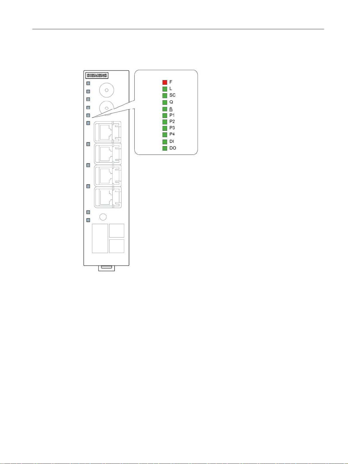
1.3 LED display
RUGGEDCOM RM1224
Operating Instructions, 10/2016, RC1260-EN-02 9
Page 10
Description of the device
1.3 LED display
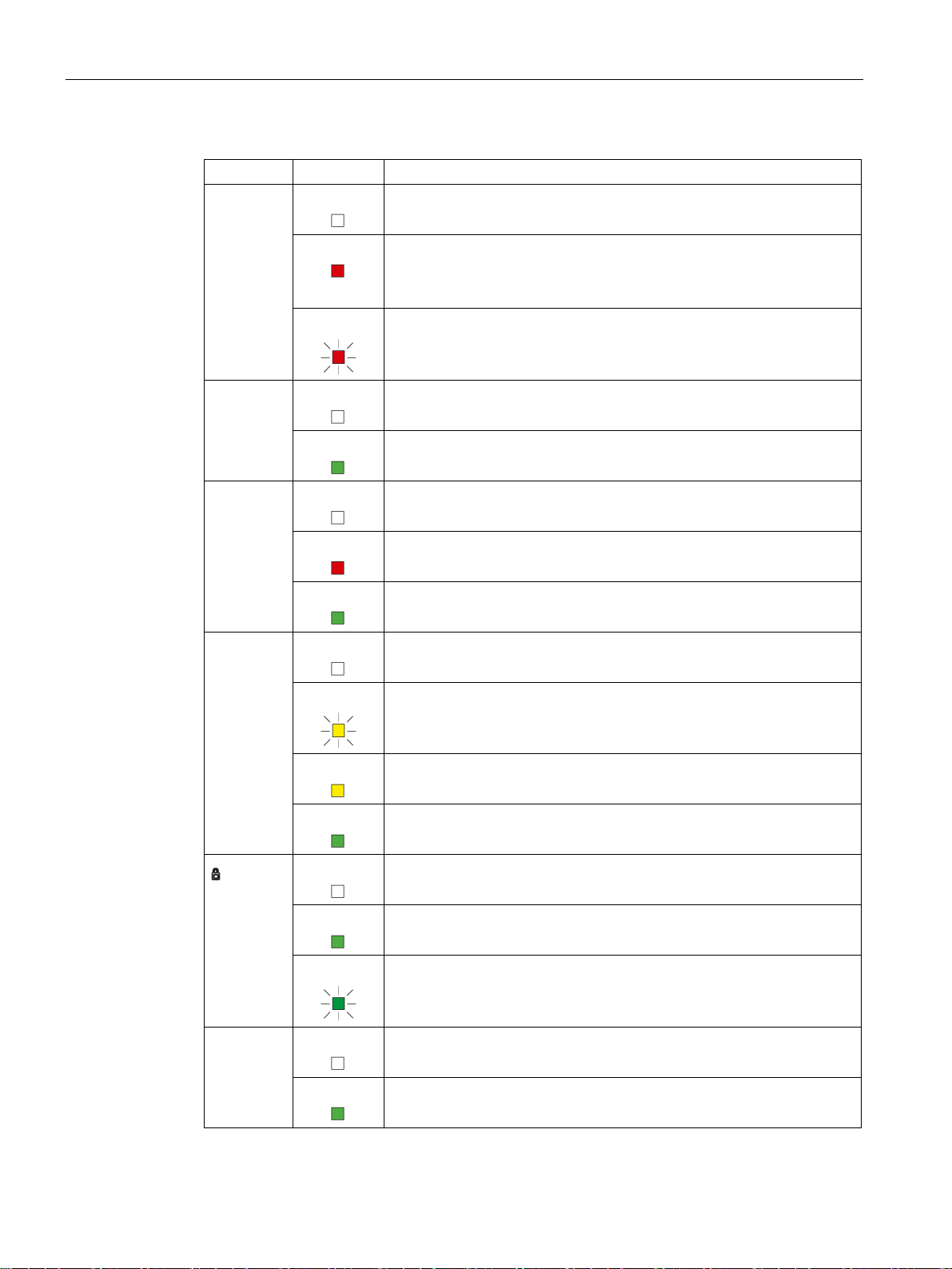
LED Status Meaning
F OFF No fault/error.
L OFF Device turned off, no power supply.
SC OFF SIM card OK, no connection.
ON The device is starting up or an error has occurred.
Possible errors/faults:
Wrong PIN number
Flashing The bootloader waits in this state for a new firmware file that you can
download using TFTP.
ON Device turned on, power supply present.
ON Wrong PIN number / SIM card error
ON Connection established
Q OFF No reception
Signal strength: < -109 dBm
Flashing Signal strength bad: -89 dBm to -109 dBm
On Signal strength medium: -73 dBm to -89 dBm
ON Signal strength good: > -73 dBm
OFF No VPN connection is established.
ON All configured VPN connections are established.
Flashing Only some of the configured VPN connections are established.
P1
P2
P3
P4
OFF Ethernet connection to local computer or LAN not established
ON Ethernet connection to local computer or LAN established
RUGGEDCOM RM1224
10 Operating Instructions, 10/2016, RC1260-EN-02
Page 11
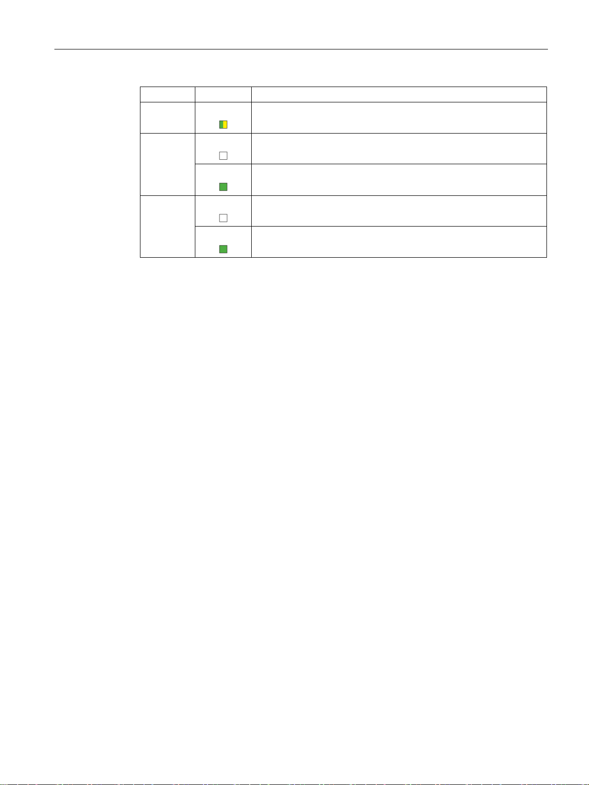
LED Status Meaning
ON Device receiving / sending data
DI OFF Digital input inactive
ON Digital input active.
DO OFF Digital output inactive
ON Digital output active.
Description of the device
1.4 SET button
RUGGEDCOM RM1224
Operating Instructions, 10/2016, RC1260-EN-02 11
Page 12
Description of the device
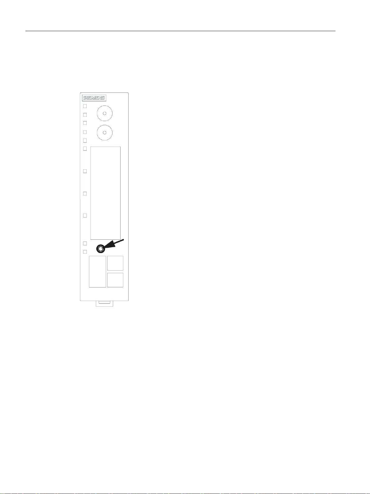
1.4 SET button
1.4 SET button
With a M-800RUGGEDCOM RM1224, the SET button is on the front of the housing beside
the LED display.
RUGGEDCOM RM1224
12 Operating Instructions, 10/2016, RC1260-EN-02
Page 13
Description of the device
1.4 SET button
The SET button has the following functions:
● Restart
Hold down the button for longer than 3 seconds to run a restart.
● Loading new firmware
If the normal procedure with the "Load & Save" menu of Web Based Management does
not work, the reset button can be used to load new firmware. This situation can occur if
there is a power outage during the normal firmware update.
– Hold down the button until the red fault LED (F) starts to flash after approximately 3
seconds.
– Now release the button. The bootloader waits in this state for a new firmware file that
you can download using TFTP.
You will find more information in the section "Service and Maintenance" in the
RUGGEDCOM RM1224 Web Based Management configuration manual.
● Reset to factory defaults
– Hold down the button until the red fault LED (F) stops flashing after approximately 10
seconds and is permanently lit.
– Now release the button and wait until the fault LED (F) goes off again. The device then
starts automatically with the factory settings and can be reached via the IP address
192.168.1.1.
You will find more information in the section "Service and Maintenance" in the
RUGGEDCOM RM1224 Web Based Management configuration manual.
WARNING
EXPLOSION HAZARD
Do not press the SET button when there is an explosive atmosphere.
RUGGEDCOM RM1224
Operating Instructions, 10/2016, RC1260-EN-02 13
Page 14

Description of the device
1.5 C-PLUG and KEY-PLUG
1.5 C-PLUG and KEY-PLUG
How it works
The C-PLUG or KEY-PLUG is used to transfer the configuration of the old device to the new
device when a device is replaced.
NOTICE
Do not remove or insert a C-PLUG / KEY-PLUG during operation!
A PLUG may only be removed or inserted when the device is turned off.
The device checks whether or not a PLUG is present at one second intervals. If it is
detected that the PLUG was removed, there is a restart.
If a valid KEY-PLUG was inserted in the device, the device changes to a defined error state
following the restart.
When the new device starts up with the PLUG, it then continues automatically with exactly
the same configuration as the old device. One exception to this can be the IP configuration if
it is set over DHCP and the DHCP server has not been reconfigured accordingly.
A reconfiguration is necessary if you use functions based on MAC addresses.
If an incorrect PLUG, for example from another product or a damaged PLUG is inserted, the
device signals an error with the "F" LED.
You can either remove the PLUG again or select the option to reformat the PLUG.
In terms of the PLUG, devices work in two modes:
● Without PLUG
The device stores the configuration in internal memory. This mode is active when no
PLUG is inserted.
● With PLUG
The configuration stored on the PLUG is displayed in WBM in "Information > PLUG". If
changes are made to the configuration, the device stores the configuration directly on the
PLUG and in the internal memory. This mode is active as soon as a PLUG is inserted. As
soon as the device is started with a PLUG inserted, the device starts up with the
configuration data on the PLUG.
License information on the KEY-PLUG
In addition to the configuration, the KEY-PLUG also contains a license that allows the use of
Siemens Remote Services.
RUGGEDCOM RM1224
14 Operating Instructions, 10/2016, RC1260-EN-02
Page 15

Article numbers
See also
Description of the device
1.5 C-PLUG and KEY-PLUG
Type Article number Description
C-PLUG 6GK1900-0AB00 Exchangeable storage medium (32 MB) for
the configuration data
KEY-PLUG SINEMA
RC
6GK5908-0PB00 Exchangeable storage medium (256 MB) to
enable the connection functionality to
SINEMA Remote Connect and for accepting
configuration data.
Inserting and removing the PLUG (Page 36)
RUGGEDCOM RM1224
Operating Instructions, 10/2016, RC1260-EN-02 15
Page 16

Page 17
Installation
2
Safety notices
When installing the device, keep to the safety notices listed below.
WARNING
If a device is operated in an ambient temperature of more than 50 °C, the temperature of
the device housing may be higher than 75 °C. The device must therefore be installed so
that it is only accessible to service personnel or users that are aware of the reason for
restricted access and the required safety measures at an ambient temperature higher than
50 °C.
Safety notices on use in hazardous areas
General safety notices relating to protection against explosion
WARNING
The device may only be operated in an environment with pollution degree 1 or 2 (see IEC
60664-1).
WARNING
When used in hazardous environments corresponding to Class I, Division 2 or Class I,
Zone 2, the device must be installed in a cabinet or a suitable enclosure.
General notes on use according to ATEX and IECEx
WARNING
To comply with EC Directive 94/9 (ATEX95) or the conditions of IECEx, this enclosure or
cabinet must meet the requirements of at least IP54 in compliance with EN 60529.
RUGGEDCOM RM1224
Operating Instructions, 10/2016, RC1260-EN-02 17
Page 18

Installation
2.1 Securing the housing
2.1 Securing the housing
Types of installation
For the device, you have the following options:
● Wall mounting (no ceiling mounting)
● Installation on a DIN rail
● Installing on the S7-300 standard rail
● Installing on the S7-1500 standard rail
Strain relief for the cables
Regardless of the type of installation, make sure that there is suitable strain relief for the
connecting cable.
Shielding of cables
If cables are installed permanently, it is advisable to remove the insulation of the shielded
cable and to establish contact on the shield/PE conductor bar.
Permitted installation direction
● Vertical installation (ventilation openings at the top and bottom)
Clearances
Keep to the minimum clearances to other components or to walls of a housing so that the
convection ventilation of the device is not blocked.
● Below at least 10 cm
● Above at least 10 cm
● With an RM1224, a clearance of 5 cm must be maintained between the sides and
adjacent devices.
2.2 Wall mounting
Note
The wall mounting must be capable of supporting four times the weight of the device, but at
least 50 N. For information on the weight, refer to the section "Technical specifications
(Page 41)".
Requirement
There is a SIM card for the device.
RUGGEDCOM RM1224
18 Operating Instructions, 10/2016, RC1260-EN-02
Page 19

Installation
Installation
2.3 Installation on the DIN rail
1. Insert the SIM card, see section "SIM card (Page 27)".
2. Prepare the drill holes for wall mounting. For the precise dimensions, refer to the section "
Dimension drawing (Page 39)".
3. Secure the device to the wall with two screws. When mounting on a wall, use mounting
fittings suitable for the type of wall.
4. Connect the power supply, refer to the section "Power supply (Page 28)".
5. Fit the connectors for the digital input and digital output, refer to the section "Digital
input/output (Page 30)".
6. Connect the antenna, refer to the section "Antennas (Page 32)".
7. Connect the device to the local network, refer to the section "Ethernet port (Page 35)".
8. Connect the terminal with as short a cable as possible ≤ 150 mm and a large cross-
sectional area ≥ 2.5 mm² to the ground of the system, see section "Grounding (Page 29)"
2.3 Installation on the DIN rail
Requirement
There is a SIM card for the device.
RUGGEDCOM RM1224
Operating Instructions, 10/2016, RC1260-EN-02 19
Page 20

Installation
2.3 Installation on the DIN rail
Installation
1. Insert the SIM card, see section "SIM card (Page 27)".
2. Place the third housing guide of the device on the top edge of the DIN rail ①.
Dismantling
3. Press the device down against the DIN rail until the spring catch locks in place ②.
4. Connect the power supply, refer to the section "Power supply (Page 28)".
5. Fit the connectors for the digital input and digital output, refer to the section "Digital
input/output (Page 30)".
6. Connect the antenna, refer to the section "Antennas (Page 32)".
7. Connect the device to the local network, refer to the section "Ethernet port (Page 35)".
8. Connect the terminal with as short a cable as possible ≤ 150 mm and a large cross-
sectional area ≥ 2.5 mm² to the ground of the system, see section "Grounding (Page 29)"
1. Disconnect all connected cables.
2. Using a screwdriver, pull down the catch on the rear of the device.
3. Pull lower part of the device away from the DIN rail.
RUGGEDCOM RM1224
20 Operating Instructions, 10/2016, RC1260-EN-02
Page 21

2.4 Installing on the S7-300 standard rail
Requirement
There is a SIM card for the device.
Installation
1. Insert the SIM card, see section "SIM card (Page 27)".
2. Place the second housing guide of the device on the top edge of the standard rail ①.
Installation
2.4 Installing on the S7-300 standard rail
3. Press the device down against the standard rail until the spring catch locks in place ②.
4. Connect the power supply, refer to the section "Power supply (Page 28)".
5. Fit the connectors for the digital input and digital output, refer to the section "Digital
input/output (Page 30)".
6. Connect the antenna, refer to the section "Antennas (Page 32)".
7. Connect the device to the local network, refer to the section "Ethernet port (Page 35)".
8. Connect the terminal with as short a cable as possible ≤ 150 mm and a large cross-
sectional area ≥ 2.5 mm² to the ground of the system, see section "Grounding (Page 29)"
RUGGEDCOM RM1224
Operating Instructions, 10/2016, RC1260-EN-02 21
Page 22

Installation
2.5 Installing on the S7-1500 standard rail
Dismantling
1. Disconnect all connected cables.
2. Using a screwdriver, pull down the catch on the rear of the device.
3. Remove the device from the standard rail.
2.5 Installing on the S7-1500 standard rail
Requirement
There is a SIM card for the device.
Installation
1. Insert the SIM card, see section "SIM card (Page 27)".
2. Place the first housing guide of the device on the top edge of the standard rail ①.
3. Using a screwdriver, pull down the catch ② on the rear of the device.
4. Swing the device down while pulling down the catch ③. After it is released, the spring
catch locks in place.
5. Connect the power supply, refer to the section "Power supply (Page 28)".
6. Fit the connectors for the digital input and digital output, refer to the section "Digital
input/output (Page 30)".
RUGGEDCOM RM1224
22 Operating Instructions, 10/2016, RC1260-EN-02
Page 23

Dismantling
Installation
2.5 Installing on the S7-1500 standard rail
7. Connect the antenna, refer to the section "Antennas (Page 32)".
8. Connect the device to the local network, refer to the section "Ethernet port (Page 35)".
9. Connect the terminal with as short a cable as possible ≤ 150 mm and a large cross-
sectional area ≥ 2.5 mm² to the ground of the system, see section "Grounding (Page 29)"
1. Disconnect all connected cables.
2. Using a screwdriver, pull down the catch on the rear of the device.
3. Remove the device from the standard rail.
RUGGEDCOM RM1224
Operating Instructions, 10/2016, RC1260-EN-02 23
Page 24

Page 25

Connecting up
3
WARNING
EXPLOSION HAZARD
SUBSTITUTION OF COMPONENTS MAY IMPAIR SUITABILITY FOR CLASS I, DIVISION
2 OR ZONE 2.
WARNING
EXPLOSION HAZARD
DO NOT OPEN WHEN ENERGIZED.
3.1 Safety when connecting up
Safety notices
When connecting up the device, keep to the safety notices listed below.
WARNING
The equipment is designed for operation with Safety Extra-Low Voltage (SELV) by a
Limited Power Source (LPS).
This means that only SELV / LPS complying with IEC 60950-1 / EN 60950-1 / VDE 0805-1
must be connected to the power supply terminals. The power supply unit for the equipment
power supply must comply with NEC Class 2, as described by the National Electrical Code
(r) (ANSI / NFPA 70).
If the equipment is connected to a redundant power supply (two separate power supplies),
both must meet these requirements.
RUGGEDCOM RM1224
Operating Instructions, 10/2016, RC1260-EN-02 25
Page 26

Connecting up
3.1 Safety when connecting up
Safety notices on use in hazardous areas
General safety notices relating to protection against explosion
WARNING
EXPLOSION HAZARD
DO NOT CONNECT OR DISCONNECT EQUIPMENT WHEN A FLAMMABLE OR
COMBUSTIBLE ATMOSPHERE IS PRESENT.
Safety notices when using the device according to Hazardous Locations (HazLoc)
If you use the device under HazLoc conditions you must also keep to the following safety
notices in addition to the general safety notices for protection against explosion:
WARNING
EXPLOSION HAZARD
DO NOT DISCONNECT WHILE CIRCUIT IS LIVE UNLESS AREA IS KNOWN TO BE
NON-HAZARDOUS.
This equipment is suitable for use in Class I, Division 2, Groups A, B, C and D or nonhazardous locations only.
This equipment is suitable for use in Class I, Zone 2, Group IIC or non-hazardous locations
only.
Safety notices for use according to ATEX and IECEx
If you use the device under ATEX or IECEx conditions you must also keep to the following
safety notices in addition to the general safety notices for protection against explosion:
WARNING
Take measures to prevent transient voltage surges of more than 40% of the rated voltage.
This is the case if you only operate devices with SELV (safety extra-low voltage).
RUGGEDCOM RM1224
26 Operating Instructions, 10/2016, RC1260-EN-02
Page 27

3.2 SIM card
NOTICE
Turn off the power supply before replacing SIM cards
Before you insert or remove the SIM card, turn off the power supply of the RM1224.
Do not open the compartment for the SIM card during operation. This can damage the SIM
card and the device.
Procedure
1. The compartment for the SIM card is located on the back of the device. Directly beside to
the compartment for the SIM card in the opening in the housing, there is a small button.
To open the drawer, press the button with a sharp object, for example a pencil.
Connecting up
3.2 SIM card
2. Place the SIM card in the tray so that the card audibly locks in place and so that its goldplated contacts remain visible.
3. Then push the tray with the SIM card completely back into the housing.
RUGGEDCOM RM1224
Operating Instructions, 10/2016, RC1260-EN-02 27
Page 28

Connecting up
3.3 Power supply
3.3 Power supply
The power supply is connected using a 5-pin terminal block. The power supply is nonfloating.
PIN Signal Description
1 L1+ 24 VDC
2 M1 Ground
3 M2 Ground
4 L2+ 24 VDC
5 Functional ground, refer to the section Grounding (Page 29)"
RUGGEDCOM RM1224
28 Operating Instructions, 10/2016, RC1260-EN-02
Page 29

External power supply
Note
Permitted external power supplies
The power supply unit to supply the RUGGEDCOM RM1224 must comply with the
requirements for a limited power source according to IEC/EN 60950-1, section 2.5.
The external power supply for the RUGGEDCOM RM1224 must meet the requirements for
NEC class 2 circuits as specified in the National Electrical Code ® (ANSI/NFPA 70).
Refer to the section Connecting up (Page 25) and the installation instructions and
instructions for use of the manufacturer of the power supply, the battery or the accumulator.
Note
External power supply for operation in China
The device may only be used with an external power supply that has a CCC approval.
Connecting up
3.4 Grounding
3.4 Grounding
EMC disturbances are diverted to ground via ground. This increases the immunity of the
data transmission.
It is crucial for the correct operation of ground that the connection to the reference potential
surface always has low impedance. Such a connection of the functional ground of the device
does not go first through the cable channel and then to the mounting plate or DIN rail
terminal, but goes directly to the mounting plate or DIN rail terminal.
The RUGGEDCOM RM1224 has a terminal for grounding, refer to the section "Power supply
(Page 28)".
The terminal is identified by the following symbol for the grounding.
1. Connect the terminal of the device with as short a cable as possible ≤ 150 mm and a
large cross-sectional area ≥ 2.5 mm² to the functional ground of the system. In many
cases, the entire metallic construction of the system serves as ground.
2. Also connect the standard rails of a system with ground.
Protective earth/functional ground
The connection of the reference potential surface with the protective earth system is
normally in the cabinet close to the power feed-in. This earth conducts fault currents to
ground safely and according to DIN/VDE 0100 is a protective earth to protect people,
animals and property from too high contact voltages.
Apart from the protective earth, there is functional grounding in the cabinet. According to
EN60204-1 (DIN/VDE 0113 T1) electrical circuits must be grounded. The chassis (0 V) is
RUGGEDCOM RM1224
Operating Instructions, 10/2016, RC1260-EN-02 29
Page 30

Connecting up
3.5 Digital input/output
grounded at one defined point. Here, once again the grounding is implemented with the
lowest leakage resistance to ground in the vicinity of the power feed-in.
With automation components, functional ground also ensures interference-free operation of
a controller. Via the functional ground, interference currents coupled in via the connecting
cables are discharged to ground.
In terms of the large-area and low impedance implementation, a functional ground set up for
this purpose generally also meets the requirements of protective earth. On the other hand,
protective earth does not always meet the requirements of functional ground. In general
while the connection for protective earth is always low resistance, it is not necessarily low
impedance.
The resistance of a connection for protective earth must always be as small as possible to
divert fault currents safely to ground. The length of a protective earth cable can therefore be
several meters (m) long, without seriously impairing this effect. For a functional ground for
diverting HF disturbances, this cable does however have impedance and is therefore not
suitable.
3.5 Digital input/output
The digital input/output (relay contact) is a floating switch with which error/fault states can be
signaled by breaking the contact.
CAUTION
Damage due to voltage being too high or too low
The voltage at the digital input/output must not exceed 30 VDC and not fall below -30 VDC,
otherwise the digital input/output will be destroyed.
RUGGEDCOM RM1224
30 Operating Instructions, 10/2016, RC1260-EN-02
Page 31

Digital input
Connecting up
3.5 Digital input/output
The 2-pin terminal block has the following assignment:
DI+ 24 VDC
DI- (input ground) -
If there is an adequate switching voltage at the digital input, the digital input is active and the
"DI" LED is lit. This means that, for example a local application connected to the in port can
trigger an alarm message by SMS outside the IP data connection.
RUGGEDCOM RM1224
Operating Instructions, 10/2016, RC1260-EN-02 31
Page 32

Connecting up
3.6 Antennas
Digital output
The 2-pin terminal block has the following assignment:
DO+ Relay 24 VDC / 1 A
DO- Relay 24 VDC / 1 A
3.6 Antennas
Note
Use the antennas from the accessories program for the RM1224 device. You will find more
detailed information in "Accessories(Page 8)". If you use a different antenna, there is no
guarantee the device will function according to the specification.
RUGGEDCOM RM1224
32 Operating Instructions, 10/2016, RC1260-EN-02
Page 33

The antenna socket for connecting the antenna is of the type SMA. The antenna used
should have an impedance of about 50 ohms.
CAUTION
Minimum clearance to the device
The device may only be operated when the distance between the device (or antenna) and
user is at least 20 cm.
Notes on lightning protection
WARNING
Danger due to lightning strikes
Antennas installed outdoors must be within the area covered by a lightning protection
system. Make sure that all conducting systems entering from outdoors are protected by
lightning protection electrical bonding.
Connecting up
3.6 Antennas
When implementing your lightning protection concept, make sure you adhere to the
requirements of the VDE 0182 or IEC 62305 standards.
Suitable lightning protectors are available in the range of accessories of RUGGEDCOM. For
more information, contact Siemens Customer Support.
● Depending on the connector, an adapter cable is required to connect to SMA.
WARNING
Danger due to lightning strikes
Installing this lightning protector between an antenna and a RUGGEDCOM RM1224 is not
adequate protection against a lightning strike. Most lightening protectors only works within
the framework of a comprehensive lightning protection concept. If you have questions, ask
a qualified specialist company.
Note
The requirements of EN61000-4-5, "Surge Immunity Test" on power supply lines with 24
VDC are met only when a Blitzductor is used:
24 VDC: BVT AVD 24 type no. 918 422
Vendor: DEHN+SÖHNE GmbH+Co.KG, Hans Dehn Str. 1, Postfach 1640, D -
92306 Neumarkt, Germany
RUGGEDCOM RM1224
Operating Instructions, 10/2016, RC1260-EN-02 33
Page 34

Connecting up
3.6 Antennas
Frequency bands in Europe, China, the USA and other regions
Depending on the frequency bands used by your mobile wireless provider, antennas must be
tuned to the following frequencies:
● In Europe, America, Africa, Asia and Australia:
– GSM 900 MHz
– DCS 1800 MHz
– UMTS 2100 MHz
– LTE 800 MHz, 900 MHz, 1800 MHz, 2100 MHz, 2600 MHz depending on the provider
● In the USA:
– LTE 700 MHz, 1900 MHz
– PCS 1900 MHz (also for UMTS)
● In Korea:
– UMTS 2100 MHz
Check with your mobile wireless provider for the suitable frequencies.
Signal quality
During installation make sure that there is a good signal strength of > -73 dBm.
If the "Q" LED is lit permanently, the signal quality is good. For more detailed information,
refer to the section "LED display (Page Error! Bookmark not defined.)".
Avoid large metal objects in the immediate vicinity.
RUGGEDCOM RM1224
34 Operating Instructions, 10/2016, RC1260-EN-02
Page 35

Antenna connectors
Connecting up
3.7 Ethernet port
3.7 Ethernet port
Connect the local network with the local applications to the Ethernet port, for example a
programmable logic controller, a machine with an Ethernet interface for remote monitoring or
a PC.
To set up the device, connect a PC with a Web browser to one of the Ethernet ports.
For the connection, use a path cable with an RJ-45 plug. You will find the properties of the
Ethernet interface in the technical specifications.
RUGGEDCOM RM1224
Operating Instructions, 10/2016, RC1260-EN-02 35
Page 36

Connecting up
3.8 Inserting and removing the PLUG
3.8 Inserting and removing the PLUG
NOTICE
Do not remove or insert a C-PLUG / KEY-PLUG during operation!
A PLUG may only be removed or inserted when the device is turned off.
The device checks whether or not a PLUG is present at one second intervals. If it is
detected that the PLUG was removed, there is a restart. If a valid KEY-PLUG was inserted
in the device, the device changes to a defined error state following the restart. With
RUGGEDCOM RM1224, the wireless interface is deactivated in this case.
Inserting the PLUG
1. Turn off the power to the device.
2. The housing of the PLUG has a protruding ridge on the long side. The slot has a groove
at this position.
Insert the PLUG correctly oriented into the slot.
RUGGEDCOM RM1224
36 Operating Instructions, 10/2016, RC1260-EN-02
Page 37

Removing the PLUG
1. Turn off the power to the device.
2. Insert a screwdriver between the front edge of the PLUG and the slot and release the
3. Remove the PLUG.
Connecting up
3.8 Inserting and removing the PLUG
PLUG.
RUGGEDCOM RM1224
Operating Instructions, 10/2016, RC1260-EN-02 37
Page 38

Page 39

Dimension drawing
4
4.1 RUGGEDCOM RM1224
Dimensions are specified in mm.
Image 4-1 RM1224 side view
RUGGEDCOM RM1224
Operating Instructions, 10/2016, RC1260-EN-02 39
Page 40

Dimension drawing
4.1 RUGGEDCOM RM1224
Image 4-2 RM1224 front view
RUGGEDCOM RM1224
40 Operating Instructions, 10/2016, RC1260-EN-02
Page 41

Technical specifications
5
Ethernet interface
Attachment to Industrial
Ethernet
Wireless interface
Antenna connector Quantity 2
Frequency bands LTE 2100 MHz = band I
LTE Transmission speed
Quantity 4
Design RJ-45 jack
Characteristics:
10/100BASE-T
Ethernet IEEE 802.3
10/100 Mbps
A1: Main antenna
A2: UMTS: RX diversity
LTE: RX MIMO
Design SMA socket (straight)
Impedance 50 Ω nominal
Antenna cable Cable length < 30 m
1800 MHz = band 3
2600 MHz = band 7
900 MHz = band 8
800 MHz = band 20
UMTS with HSPA+ 900 MHz = band VIII
1800 MHz = band III
2100 MHz = band I
GSM 850 MHz = GSM 850
1900 MHz = GSM 1900
Downlink: up to 100 Mbps
Uplink: up to 50 Mbps
UMTS with HSPA+ Transmission speed
EGPRS Properties Multislot class 12, end device class B
Transmission speed
GPRS Properties Multislot class 12, end device class B, coding
RUGGEDCOM RM1224
Operating Instructions, 10/2016, RC1260-EN-02 41
HSDPA (downlink): up to 14.4 Mbps
HSUPA (uplink): up to 5.76 Mbps
Coding scheme downlink: CS 1 ... 4, MCS 1
... 9
Coding scheme uplink: CS 1 ... 4, MCS 1 ... 9
Downlink: up to 237 kbps:
Uplink: up to 237 kbps:
scheme 1 … 4
Page 42

Technical specifications
Transmission speed
Downlink: up to 85.6 kbps.
Uplink: up to 85.6 kbps.
GSM (CSD dial-in) Properties Radio Link Protocol (RLP) V.110, non-
transparent
Transmission speed up to 14.4 kbps
SMS (TX) Properties Text mode, SMSoverIP
Electrical data
Power supply Quantity 1
Design Terminal block, 5 terminals
Properties Input voltage:
12 to 24 VDC
min. 10.8 VDC, max. 28.8 VDC
Maximum power consumption 8 W
Maximum cable length < 3 m
Digital input Quantity 1
Design Terminal block, 2 terminals
Properties Rated voltage 24 VDC Safety Extra Low Voltage
(SELV)
For state "1": 10 to 30 VDC
For state "0": -30 to 3 VDC
Maximum input current 8 mA
Maximum cable length < 3 m
Inputs isolated from electronics.
Digital output Quantity 1
Design Terminal block, 2 terminals
Properties Rated voltage 24 VDC Safety Extra Low Voltage
(SELV)
Relay, internally not current limited
Maximum current carrying capacity 1 A
Maximum cable length < 3 m
Output isolated from electronics
Permitted ambient conditions
Ambient temperature
1 2
During operation -20 ℃ to +75 ℃
During storage -40 ℃ to +85 ℃
During transporta-
-40 ℃ to +85 ℃
tion
Relative humidity During operation ≤ 95% at 25 °C, no condensation
Design, dimensions and weight
Module format Compact module S7-1500
1
UL certified operational temperature range -20 °C to +70 °C
2
IEC environmentally type tested (16 hours) from -40 °C to +75 °C
RUGGEDCOM RM1224
42 Operating Instructions, 10/2016, RC1260-EN-02
Page 43

Degree of protection IP20
Weight 290 g
Dimensions (W x H x D) 34.8 x 147 x 134.7 mm
Installation options
Wall mounting
Mounting on a DIN rail
Mounting on an S7-300 standard rail
Mounting on an S7-1500 standard rail
Installation direction Vertical
(ventilation openings at the top and bottom)
Clearance between sides and adjacent device: 5
cm
Product functions
Firewall and security
Stateful inspection
Packet filter
IPsec VPN for up to 20 connections
SINEMA RC client
Password protection
Technical specifications
Router functions
NAPT (port forwarding)
NAT (IP masquerading)
NAT traversal
NETMAP
Dynamic DNS client
DNS cache
NTP
Remote logging
Connection monitoring
Alarm SMS
Sending SMS messages from the local area
network
Configuration / management
Web-based administration user interface
(WBM)
Command Line Interface (CLI)
Remote access with HTTPS
SNMP and SNMP traps
Type tests
IEC 60068-2-1 Cold Temperature
-40 ℃ for 16 hours
(Test Ad)
IEC 60068-2-2 Dry Heat (Test Bd) +75 ℃ for 16 hours
RUGGEDCOM RM1224
Operating Instructions, 10/2016, RC1260-EN-02 43
Page 44

Page 45

Approvals
A
Approvals issued
Note
Issued approvals on the type plate of the device
The specified approvals apply only when the corresponding mark is printed on the product.
You can check which of the following approvals have been granted for your product by the
markings on the type plate.
Approvals for shipbuilding are not printed on the device type plate.
WARNING
Personal injury and property damage can occur
The installation of expansions that are not approved for RUGGEDCOM products or their
target systems may violate the requirements and regulations for safety and electromagnetic
compatibility.
Only use expansions that are approved for the system.
RUGGEDCOM RM1224
Operating Instructions, 10/2016, RC1260-EN-02 45
Page 46

Approvals
● Keep to the installation guidelines
The devices meet the requirements if you adhere to the installation and safety
instructions contained in this documentation and in the following documentation
when installing and operating the devices.
● You can always find the latest documentation on the Internet
The current descriptions of the currently available products can always be found on
the Internet under the specified entry IDs/Internet pages:
– "Industrial Ethernet / PROFINET Industrial Ethernet" System Manual
– "Industrial Ethernet / PROFINET - Passive network components" System Manual
You will find information on the system manuals in the section "ID = 27069465
(http://support.automation.siemens.com/WW/view/en/27069465)", in "Further
documentation".
– "EMC Installation Guidelines" configuration manual
ID = 60612658 (http://support.automation.siemens.com/WW/view/en/60612658)
● Working on the device
To protect the device from electrostatic discharge, personnel must first discharge
any electrostatic charge from their body before touching the device.
Note
The test was performed with a device and a connected communications partner that also
meets the requirements of the standards listed above.
When operating the device with a communications partner that does not comply with
these standards, adherence to the corresponding values cannot be guaranteed.
Current approvals on the Internet
RUGGEDCOM products are regularly submitted to the relevant authorities and approval
centers for approvals relating to specific markets and applications.
You will also find the current approvals for the product on the Internet pages of Siemens
Automation Customer Support under the following entry ID:
80046561 (http://support.automation.siemens.com/WW/view/en/80046561/134200)
→ "Entry list" tab, entry type "Certificates"
National approvals
You will find an overview of the country-specific wireless approvals of RUGGEDCOM
devices with GSM or UMTS services on the Internet pages of Siemens Automation
Customer Support. You will find the link to the document on the following page:
ik-Info (www.siemens.com/simatic-net/ik-info)
RUGGEDCOM RM1224
46 Operating Instructions, 10/2016, RC1260-EN-02
Page 47

A.1 EU declaration of conformity
The EC Declaration of Conformity is available for all responsible authorities at:
Siemens Aktiengesellschaft
Process Industries and Drives,
Process Automation
DE-76181 Karlsruhe
Germany
You will find the EC declaration of conformity for these products on the Internet pages of
Siemens Industry Online Support
(https://support.industry.siemens.com/cs/ww/en/ps/15914/cert).
The RUGGEDCOM products described in these Operating Instructions meet the
requirements of the following EC directives:
● 94/9/EC (ATEX)
Approvals
A.1 EU declaration of conformity
ATEX - Directive of the European Parliament and the Council of 23 March 1994 on the
approximation of the laws of the Member States concerning equipment and protective
systems intended for use in potentially explosive atmospheres.
● 1999/5/EC (R&TTE)
R&TTE directive of the European Parliament and of the Council of 9 March 1999 on
Radio Equipment and Telecommunications Terminal Equipment and the mutual
recognition of their conformity.
● 2011/65/EU (RoHS)
RoHS directive of the European Parliament and of the Council of 8 June 2011 on the
restriction of the use of certain hazardous substances in electrical and electronic
equipment.
Which of the described standards apply to the product can be found in Products (Page 50).
A.1.1 R&TTE
A.1.1.1 Protection of health and safety
Article 3 (1) a) of the R&TTE directive
RUGGEDCOM RM1224
Operating Instructions, 10/2016, RC1260-EN-02 47
Page 48

Approvals
A.1 EU declaration of conformity
Harmonized standards:
3 EN 60950-1+A1+A2+A11+A12
Information technology equipment - Safety - Part 1: General requirements
4 EN 62479
Assessment of the compliance of low power electronic and electrical equipment
with the basic restrictions related to human exposure to electromagnetic fields (10
MHz to 300 GHz)
5 EN 62311
Assessment of electronic and electrical equipment related to human exposure restrictions for electromagnetic fields (0 Hz – 300 GHz)
A.1.1.2 EMC
Article 3 (1) b) of the R&TTE directive
Harmonized standards:
6 ETSI EN 301 489-1
Electromagnetic compatibility and radio spectrum matters (ERM) - Electromagnetic
compatibility for radio equipment and services - Part 1 : Common technical requirements
7 ETSI EN 301 489-7
Electromagnetic compatibility and radio spectrum matters (ERM) - Electromagnetic
compatibility for radio equipment and services - Part 7 : Specific conditions for
mobile and portable radio and ancillary equipment of digital cellular radio telecommunications systems (GSM and DCS).
8 ETSI EN 301 489-24
Electromagnetic compatibility and radio spectrum matters (ERM) - Electromagnetic
compatibility for radio equipment and services - Part 24 : Specific conditions for
mobile and portable IMT-2000 CDMA Direct Spread (UTRA) radio and ancillary
equipment.
9 EN 61000-6-1
Electromagnetic compatibility (EMC) - Part 6-1: Generic standards - Immunity for
residential, commercial and light-industrial environments
10 EN 61000-6-2+AC
Electromagnetic compatibility (EMC) - Part 6-2: Generic standards - Immunity for
industrial environments
11 EN 61000-6-3+A1+AC
Electromagnetic compatibility (EMC) - Part 6-3: Generic standards - Emission
standard for residential, commercial and light-industrial environments
12 EN 61000-6-4+A1
Electromagnetic compatibility (EMC) - Part 6-4: Generic standards - Emission
standard for industrial environments
RUGGEDCOM RM1224
48 Operating Instructions, 10/2016, RC1260-EN-02
Page 49

13 EN 55022 +AC:Class A / B
cts with
Information technology equipment - Radio disturbance characteristics - Limits and
methods of measurement
14 EN 55024
Information technology equipment - Immunity characteristics -Limits and characteristics - Limits and methods of measurement
15 EN 50121-4
Railway applications - Electromagnetic Compatibility - Emission and Immunity of
the Signaling and Telecommunications Apparatus
A.1.1.3 Efficient use of the radio spectrum
Article 3 (2) of the R&TTE directive
16 ETSI EN 301 511
Global System for Mobile communications (GSM); Harmonized EN for mobile stations in the GSM 900 and GSM 1800 bands covering essential requirements of
article 3.2 of the R&TTE directive
17 ETSI EN 301 908-1
IMT cellular networks - Harmonized EN covering the essential requirements of article 3.2 of the R&TTE directive - Part 1: Introduction and common requirements
18 ETSI EN 301 908-2
IMT cellular networks - Harmonized EN covering the essential requirements of article 3.2 of the R&TTE directive - Part 2: CDMA Direct Spread (UTRA FDD) User
Equipment (UE)
19 ETSI EN 301 908-13
IMT cellular networks - Harmonized EN covering the essential requirements of article 3.2 of the R&TTE directive - Part 13: Further developed universal terrestrial
wireless access (E-UTRA) end devices (UE)
Approvals
A.1 EU declaration of conformity
A.1.2 RoHS
RoHS directive (restriction of the use of certain hazardous substances)
The RUGGEDCOM products described in these operating instructions meet the
requirements of the EC directive 2011/65/EC for the restriction of the use of certain
hazardous substances in electrical and electronic equipment:
Applied standard:
20 EN 50581
Technical documentation for the assessment electrical and electronic produ
respect to restriction of hazardous substances
RUGGEDCOM RM1224
Operating Instructions, 10/2016, RC1260-EN-02 49
Page 50

Approvals
A.2 RCM / C-TICK
A.1.3 Railway
Applied standard:
21 EN 50155
A.1.4 Products
Product designation and standards
The standards that apply to the product are described in R&TTE (Page 47) and RoHS
(Page 49).
● 3, 5, 6, 7, 8, 15, 16, 17, 18, 19
Antenna gain
Note
Railway Applications - Electronic Equipment Used on Rolling Stock
Depending on the selected wireless standard and the wireless frequency used, antennas
with different antenna gains can be used. If you change the frequency band during
operation, it is possible that the maximum permitted antenna again also changes. Check
whether the antenna you are using is approved for the changed frequency range. If
necessary, change the antenna so as not to violate the operational requirements. Or use an
antenna with a gain less than 3.58 dBi to cover all bands.
Frequency band Maximum antenna gain in dBi
GSM /GPRS 900 3.58
E-GPRS 900 9.88
GSM /GPRS 1800 9.84
E-GPRS 1800 13.85
UMTS FDD1 13.35
UMTS FDD III 13.45
UMTS VIII 10.27
LTE FDD 3 12.66
LTE FDD 7 13.86
LTE FDD 8 10.58
LTE FDD 20 8.76
A.2 RCM / C-TICK
The products meet the requirements of the AS/NZS CISPR11 : 2011 standard (Industrial,
scientific and medical equipment - Radio- frequency disturbance characteristics - Limits and
methods of measurement).
RUGGEDCOM RM1224
50 Operating Instructions, 10/2016, RC1260-EN-02
Page 51

A.3 IECEx
IECEx
The RUGGEDCOM products meet the requirements of explosion protection according to
IECEx.
IECEx classification:
Ex nA IIC T4 Gc
DEK 14.0025X
The products meet the requirements of the following standards:
The current versions of the standards can be seen in the current version of the IECEx
certificate DEK 14.0025X.
Approvals
A.3 IECEx
● IEC 60079-0 : Explosive atmospheres - Part 0: Equipment - General requirements
● IEC 60079-15 : Explosive atmospheres - Part 15: Equipment protection by type of
protection "n"
A.4 FM certification
Approved for use in
Cl. 1, Div. 2, GP. A, B, C, D, T4
Cl. 1, Zone 2, GP. IIC T4
Ta: -20 °C to + 60 C
For the use of the product in hazardous areas, the following requirements are met:
● Factory Mutual Approval Standard Class Number 3611
● FM Hazardous (Classified) Location Electrical Equipment:
Non Incendive / Class I / Division 2 / Groups A,B,C,D / T4 and
Non Incendive / Class I / Zone 2 / Group IIC / T4
A.5 UL certification (product safety)
RUGGEDCOM RM1224
Operating Instructions, 10/2016, RC1260-EN-02 51
Page 52

Approvals
A.6 EAC
Applied standards
● UL 60950-1 (Information Technology Equipment)
● UL 508 (Industrial Control Equipment)
● CSA C22.2 No.60950-1 (Information Technology Equipment)
UL certified operational temperature range -20 °C to +70 °C.
IEC environmentally type tested (16 hours) from -40 °C to +75 °C.
A.6 EAC
Marking for the customs union
EAC (Eurasian Conformity)
Customs union of Russia, Belarus and Kazakhstan
Declaration of the conformity according to the technical regulations of the customs union
(TR CU)
RUGGEDCOM RM1224
52 Operating Instructions, 10/2016, RC1260-EN-02
Page 53

Index
A
Accessories, 8
C
Connecting up
Digital input, 31
Digital output, 32
Ethernet interface, 35
Grounding, 29
Power supply, 28
SIM card, 27
C-PLUG, 14
D
Digital input, 31
Digital output, 32
Dimension drawing
DIN rail, 20
E
Ethernet interface, 35
External power supply
China, 29
L
LED display
P
Power supply, 28
Product property, 7
S
S7-1500 standard rail, 22
S7-300 standard rail, 21
Safety notices
for installation, 17
Use in hazardous areas, 17, 25
when connecting up, 25
Scope of delivery, 7
SET button, 12
Signal quality, 34
SIM card, 27
System manual, 46
W
Wall mounting, 19
G
Glossary, 4
Grounding, 29
I
Installation
DIN rail, 20
S7-1500 standard rail, 22, 22
S7-300 standard rail, 21
Wall, 19
K
KEY-PLUG, 14
RUGGEDCOM RM1224
Operating Instructions, 10/2016, RC1260-EN-02 53
Page 54

Index
RUGGEDCOM RM1224
54 Operating Instructions, 10/2016, RC1260-EN-02
 Loading...