

Page 1

Preface
RUGGEDCOM MX5000RE
Installation Guide
Introduction
Installing the Device
Device Management
Modules
Technical Specifications
Certification
1
2
3
4
5
6
6/2019
RC1060-EN-12
Page 2

RUGGEDCOM MX5000RE
Installation Guide
Copyright © 2019 Siemens Canada Ltd
All rights reserved. Dissemination or reproduction of this document, or evaluation and communication of its contents, is not authorized
except where expressly permitted. Violations are liable for damages. All rights reserved, particularly for the purposes of patent application or
trademark registration.
This document contains proprietary information, which is protected by copyright. All rights are reserved. No part of this document may be
photocopied, reproduced or translated to another language without the prior written consent of Siemens Canada Ltd.
Disclaimer Of Liability
Siemens has verified the contents of this document against the hardware and/or software described. However, deviations between the product
and the documentation may exist.
Siemens shall not be liable for any errors or omissions contained herein or for consequential damages in connection with the furnishing,
performance, or use of this material.
The information given in this document is reviewed regularly and any necessary corrections will be included in subsequent editions. We
appreciate any suggested improvements. We reserve the right to make technical improvements without notice.
Registered Trademarks
RUGGEDCOM™ and ROS™ are trademarks of Siemens Canada Ltd.
Linux® is the registered trademark of Linus Torvalds in the United States and other countries.
The registered trademark Linux® is used pursuant to a sublicense from LMI, the exclusive licensee of Linus Torvalds, owner of the mark on a
world-wide basis.
Other designations in this manual might be trademarks whose use by third parties for their own purposes would infringe the rights of the
owner.
Security Information
Siemens provides products and solutions with industrial security functions that support the secure operation of plants, machines, equipment
and/or networks. They are important components in a holistic industrial security concept. With this in mind, Siemens' products and solutions
undergo continuous development. Siemens recommends strongly that you regularly check for product updates.
For the secure operation of Siemens products and solutions, it is necessary to take suitable preventive action (e.g. cell protection concept) and
integrate each component into a holistic, state-of-the-art industrial security concept. Third-party products that may be in use should also be
considered. For more information about industrial security, visit https://www.siemens.com/industrialsecurity.
To stay informed about product updates as they occur, sign up for a product-specific newsletter. For more information, visit https://
support.automation.siemens.com.
Warranty
Siemens warrants this product for a period of five (5) years from the date of purchase, conditional upon the return to factory for maintenance
during the warranty term. This product contains no user-serviceable parts. Attempted service by unauthorized personnel shall render all
warranties null and void. The warranties set forth in this article are exclusive and are in lieu of all other warranties, performance guarantees
and conditions whether written or oral, statutory, express or implied (including all warranties and conditions of merchantability and fitness for
a particular purpose, and all warranties and conditions arising from course of dealing or usage or trade). Correction of nonconformities in the
manner and for the period of time provided above shall constitute the Seller’s sole liability and the Customer’s exclusive remedy for defective
or nonconforming goods or services whether claims of the Customer are based in contract (including fundamental breach), in tort (including
negligence and strict liability) or otherwise.
For warranty details, visit https://www.siemens.com/ruggedcom or contact a Siemens customer service representative.
Contacting Siemens
Address
Siemens Canada Ltd
Telephone
Toll-free: 1 888 264 0006
E-mail
ruggedcom.info.i-ia@siemens.com
ii
Page 3

RUGGEDCOM MX5000RE
Installation Guide
Industry Sector
300 Applewood Crescent
Concord, Ontario
Canada, L4K 5C7
Tel: +1 905 856 5288
Fax: +1 905 856 1995
Web
https://www.siemens.com/ruggedcom
iii
Page 4

RUGGEDCOM MX5000RE
Installation Guide
iv
Page 5

RUGGEDCOM MX5000RE
Installation Guide
Table of Contents
Table of Contents
Preface ............................................................................................................ vii
Alerts ................................................................................................................................................. vii
Related Documents ............................................................................................................................ viii
Accessing Documentation .................................................................................................................. viii
Training ............................................................................................................................................ viii
Customer Support .............................................................................................................................. viii
Chapter 1
Introduction ..................................................................................................... 1
1.1Feature Highlights ........................................................................................................................ 2
1.2Description ................................................................................................................................... 2
1.3Required Tools and Materials ......................................................................................................... 4
1.4Cabling Recommendations ............................................................................................................ 5
1.4.1Protection On Twisted-Pair Data Ports .................................................................................. 5
1.4.2Gigabit Ethernet 1000Base-TX Cabling Recommendations ..................................................... 5
1.4.3Supported Fiber Optic Cables .............................................................................................. 6
1.5Patch Panels ................................................................................................................................. 6
1.6Decommissioning and Disposal ...................................................................................................... 7
Chapter 2
Installing the Device ......................................................................................... 9
2.1General Procedure ...................................................................................................................... 10
2.2Unpacking the Device ................................................................................................................. 11
2.3Installing the Power Supply Patch Cables ...................................................................................... 11
2.4Installing the Chassis Ground Connection ..................................................................................... 13
2.5Connecting the Failsafe Alarm Relay ............................................................................................. 14
2.6Installing the Fan Tray Cables ...................................................................................................... 15
2.7Installing the Mounting Brackets .................................................................................................. 17
2.8Installing the EMI Gaskets ........................................................................................................... 18
2.9Assembling the RUGGEDCOM MX5000 and RUGGEDCOM MX5000RE .............................................. 19
2.10Installing the Fan Tray ............................................................................................................... 21
2.11Installing the Patch Panels ......................................................................................................... 23
2.12Connecting the Network Cables ................................................................................................. 24
2.13Installing the Front Panel ........................................................................................................... 24
2.14Mounting the RUGGEDCOM MX5000RE ...................................................................................... 25
v
Page 6

Table of Contents
2.15Connecting Power ..................................................................................................................... 26
2.15.1Connecting Power to the Enclosure ................................................................................. 27
Chapter 3
RUGGEDCOM MX5000RE
Installation Guide
Device Management ....................................................................................... 29
3.1Connecting to the Device ............................................................................................................ 29
3.2Configuring the Device ................................................................................................................ 30
3.3Accessing the CompactFlash Card ................................................................................................ 30
Chapter 4
Modules .......................................................................................................... 33
4.1Available Modules ....................................................................................................................... 34
4.2Installing/Removing Line Modules ................................................................................................ 37
4.3Installing/Removing Power Supply Modules ................................................................................... 39
Chapter 5
Technical Specifications .................................................................................. 43
5.1Power Supply Specifications ........................................................................................................ 43
5.2Failsafe Relay Specifications ......................................................................................................... 43
5.3Operating Environment ............................................................................................................... 44
5.4Mechanical Specifications ............................................................................................................ 44
5.5Dimension Drawings ................................................................................................................... 44
Chapter 6
Certification .................................................................................................... 47
6.1Approvals ................................................................................................................................... 47
6.1.1TÜV SÜD ......................................................................................................................... 47
6.1.2European Commission (EC) ............................................................................................... 48
6.1.3 FCC ................................................................................................................................. 48
6.1.4FDA/CDRH ........................................................................................................................ 48
6.1.5 ISED ................................................................................................................................ 49
6.1.6 ISO .................................................................................................................................. 49
6.1.7 RoHS ............................................................................................................................... 49
6.1.8Other Approvals ............................................................................................................... 49
6.2MIL-STD Ratings .......................................................................................................................... 50
6.3EMC and Environmental Type Tests .............................................................................................. 50
vi
Page 7
RUGGEDCOM MX5000RE
Installation Guide
Preface
This guide describes the RUGGEDCOM RUGGEDCOM MX5000RE. It describes the major features of the device,
installation, commissioning and important technical specifications.
It is intended for use by network technical support personnel who are responsible for the installation,
commissioning and maintenance of the device. It is also recommended for use by network and system planners,
system programmers, and line technicians.
CONTENTS
• “Alerts”
• “Related Documents”
• “Accessing Documentation”
• “Training”
• “Customer Support”
Preface
Alerts
The following types of alerts are used when necessary to highlight important information.
DANGER!
DANGER alerts describe imminently hazardous situations that, if not avoided, will result in death or
serious injury.
WARNING!
WARNING alerts describe hazardous situations that, if not avoided, may result in serious injury and/or
equipment damage.
CAUTION!
CAUTION alerts describe hazardous situations that, if not avoided, may result in equipment damage.
IMPORTANT!
IMPORTANT alerts provide important information that should be known before performing a procedure
or step, or using a feature.
NOTE
NOTE alerts provide additional information, such as facts, tips and details.
Alerts vii
Page 8

Preface
RUGGEDCOM MX5000RE
Installation Guide
Related Documents
Other documents that may be of interest include:
• ROX II CLI User Guide [https://support.industry.siemens.com/cs/ww/en/view/109481701]
• ROX II Web Interface User Guide [https://support.industry.siemens.com/cs/ww/en/view/109481702]
• RUGGEDCOM Module Catalog [https://support.industry.siemens.com/cs/ww/en/view/109748780]
Accessing Documentation
The latest user documentation for RUGGEDCOM MX5000RE is available online at
https://www.siemens.com/ruggedcom. To request or inquire about a user document, contact Siemens Customer
Support.
Training
Siemens offers a wide range of educational services ranging from in-house training of standard courses on
networking, Ethernet switches and routers, to on-site customized courses tailored to the customer's needs,
experience and application.
Siemens' Educational Services team thrives on providing our customers with the essential practical skills to make
sure users have the right knowledge and expertise to understand the various technologies associated with critical
communications network infrastructure technologies.
Siemens' unique mix of IT/Telecommunications expertise combined with domain knowledge in the utility,
transportation and industrial markets, allows Siemens to provide training specific to the customer's application.
For more information about training services and course availability, visit https://www.siemens.com/ruggedcom or
contact a Siemens Sales representative.
Customer Support
Customer support is available 24 hours, 7 days a week for all Siemens customers. For technical support or general
information, contact Siemens Customer Support through any of the following methods:
Online
Visit http://www.siemens.com/automation/support-request to submit a Support Request (SR) or check
on the status of an existing SR.
Telephone
Call a local hotline center to submit a Support Request (SR). To locate a local hotline center, visit http://
www.automation.siemens.com/mcms/aspa-db/en/automation-technology/Pages/default.aspx.
viii Related Documents
Page 9

RUGGEDCOM MX5000RE
Installation Guide
Preface
Mobile App
Install the Industry Online Support app by Siemens AG on any Android, Apple iOS or Windows mobile
device and be able to:
• Access Siemens' extensive library of support documentation, including FAQs and manuals
• Submit SRs or check on the status of an existing SR
• Contact a local Siemens representative from Sales, Technical Support, Training, etc.
• Ask questions or share knowledge with fellow Siemens customers and the support community
Customer Support ix
Page 10

Preface
RUGGEDCOM MX5000RE
Installation Guide
x Customer Support
Page 11

RUGGEDCOM MX5000RE
Installation Guide
Introduction
Introduction
The RUGGEDCOM RUGGEDCOM MX5000RE is a MIL-STD, high-port density routing and switching platform,
designed to operate in the most demanding environments.The RUGGEDCOM MX5000RE can withstand high levels
of electromagnetic interference, radio frequency interference, and a wide temperature range of -40 to 85 °C (-40
to 185 °F). The RUGGEDCOM MX5000RE is designed to meet the challenging climatic and environmental demands
found in utility, industrial, and military network applications.
The RUGGEDCOM MX5000RE's superior hardware design, coupled with the embedded RUGGEDCOM MX5000RE
operating system, provides improved system reliability for the most demanding network applications. The cyber
security and networking features make it ideally suited for creating secure Ethernet networks for mission critical,
real-time, control applications.
The RUGGEDCOM MX5000RE is a scalable, modular platform providing the ability to change the configuration as
the network grows and needs change.
The enclosure is a tough, welded aluminum, hard-mount enclosure built to house Siemens networking products
and provide MIL-STD ratings for shock, vibration, emissions, immunity, temperature, and humidity. Ten external
patch panels with up to 64 MIL grade round connectors provide tremendous flexibility and allow the enclosure to
be employed in many diverse applications. A variety of patch panel cable assemblies allow convenient and simple
mapping from internal electronics to the outside world.
The enclosure is rated for IP65 ingress protection, meaning that it is dust tight and can withstand water from a
nozzle in any direction. Constructed with aluminum extrusions with fins on both sides and combined with high
reliability internal circulation fans, the enclosure optimizes heat transfer without the exchange of outside air and
improves the MTBF for the enclosed electronics.
The RUGGEDCOM MX5000 installed with the enclosure provides an extremely flexible package with MIL-STD
approvals, continuing Siemens's tradition of pioneering advanced networking solutions specifically for the harsh
environments found in military applications.
This section provides more information about the RUGGEDCOM MX5000RE.
Chapter 1
CONTENTS
• Section1.1, “Feature Highlights”
• Section1.2, “Description”
• Section1.3, “Required Tools and Materials”
• Section1.4, “Cabling Recommendations”
• Section1.5, “Patch Panels”
• Section1.6, “Decommissioning and Disposal”
1
Page 12

Chapter 1
Introduction
Section1.1
Feature Highlights
Ethernet Ports
• Up to 48 x 10/100Base-TX copper Ethernet ports
• Up to 48 x 100Base-FX fiber optical Ethernet ports
• Up to 2 x Gigabit Ethernet ports
• Long-haul optics allow distances up to 90 km (56 mi)
• Multiple connector types: ST, MTRJ, LC, SC
Reliability in Harsh Environments
• Immunity to EMI and high voltage electrical transients
• Zero-Packet-Loss Technology
• -40 to 85 °C (-40 to 185 °F) operating temperature (no fans within chassis or modules)
• [Optional] Conformal coated printed circuit boards
Universal Power Supply Options
• Fully integrated, dual-redundant (optional) power supplies
• Universal high voltage ranges: 88-300 VDC or 85-264 VAC
• Terminal blocks for reliable maintenance-free connections
• CSA/UL 60950-1 safety approved to 85 °C (185 °F)
RUGGEDCOM MX5000RE
Installation Guide
Enclosure Features
• Welded 6061-T4 aluminum extrusion construction
• Welded 6061-T6 aluminum mounting brackets for MIL901D hard mounting
• Configurable patch panel allows up to 64 MIL grade circular connectors for both copper and fiber media
• Integrated cable management for strain relief
• Removable front panel with EMI glass for service and maintenance
• Hard-mounted brackets fit standard 48 cm (19 in) rack mount equipment
• Dual internal MIL grade high reliability fans minimize internal temperature gradient with no outside air
exchange
• IEC 60529 IP65 rated; dust tight, water jets
Section1.2
Description
The RUGGEDCOM MX5000RE features various ports, controls and indicator LEDs on individual modules and the
front panel for connecting, configuring and troubleshooting the device.
2 Feature Highlights
Page 13
RUGGEDCOM MX5000RE
4
6
7
8
10
11
4
5
1
2
3
9
12
43 5 6
1
1
2
Installation Guide
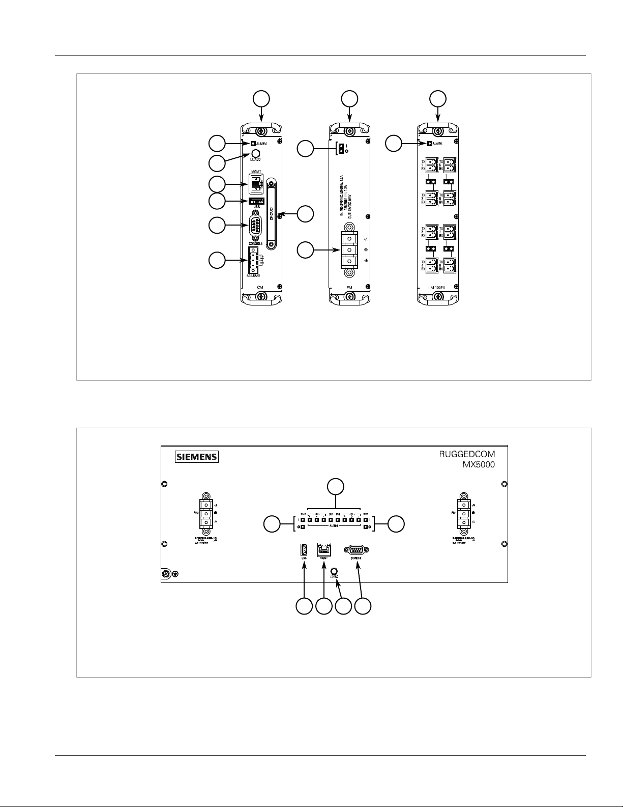
Figure1:RUGGEDCOM MX5000RE Modules
1.Control Module 2.Power Supply Module 3.Line Module (Typical) 4.Alarm Indicator LED 5.Lamp Test/Alarm Cut-Off (LT/ACO)
Button 6.Management Ethernet Port 7.Utility USB Port 8.RS232 Serial Console Port (DB9) 9.Failsafe Alarm Relay 10.CompactFlash
Card Port 11.Power Supply Module Indicator LEDs 12.Power Supply Terminal Block
Chapter 1
Introduction
When the RUGGEDCOM MX5000RE is configured for rack front mounting, these ports, controls and LEDs are
located on the front panel.
Figure2:Front Panel
1.Power Supply Module Indicator LEDs 2.Alarm Indicator LEDs 3.Utility USB Port 4.Management Ethernet Port 5.Lamp Test/Alarm
Cut-Off (LT/ACO) Button 6.RS232 Serial Console Port (DB9)
Description 3
Page 14
Chapter 1
Introduction
Figure3:Front Panel – Fan Controller Option
Power Supply Module Indicator LEDs Indicate the status of the power modules.
• I = The power supply is receiving power
• O = The power supply is supplying power
Alarm Indicator LED Indicates when an alarm condition exists.
• Green = Alarms cleared/acknowledged
• Red = Alarm
RUGGEDCOM MX5000RE
Installation Guide
Lamp Test/Alarm Cut-Off (LT/ACO) Button This button performs two functions:
• Press and hold this button to test all indicator LEDs
• Press and release this button to acknowledge an active alarm
Management Port This 10/100Base-T Ethernet port is used for system management that is out-of-band from the
Utility USB Port Use the USB port to upgrade the RUGGEDCOM ROX II software or install files, such as
Compact Flash Card Port Houses the CompactFlash (CF) card that contains active and backup installations of
RS232 Serial Console Port The serial console port is for interfacing directly with the device and accessing initial
Failsafe Alarm Relay Latches to default state when a power disruption or other alarm condition occurs. For more
Power Supply Terminal Block A pluggable terminal block. For more information, refer to Section2.15, “Connecting Power”.
switch fabric.
configuration files and feature key files. For more information, refer to the RUGGEDCOM ROX
II User Guide for the RUGGEDCOM MX5000RE.
RUGGEDCOM ROX II, along with the configuration database and other system data. For more
information, refer to Section3.3, “Accessing the CompactFlash Card”.
management functions. For information about connecting to the device via the serial
console port, refer to Section3.1, “Connecting to the Device”.
information, refer to:
• Section2.5, “Connecting the Failsafe Alarm Relay”
• Section5.2, “Failsafe Relay Specifications”
Section1.3
Required Tools and Materials
The following tools and materials are required to install the RUGGEDCOM MX5000RE:
4 Required Tools and Materials
Page 15

RUGGEDCOM MX5000RE
Installation Guide
Tools/Materials Purpose
AC or DC power cord (16 AWG) For connecting power to the device.
CAT-5 Ethernet cables For connecting the device to the network.
Flathead screwdriver For assembling the RUGGEDCOM MX5000RE
Phillips screwdriver For assembling the RUGGEDCOM MX5000RE
Section1.4
Cabling Recommendations
Before connecting the device, be aware of the recommendations and considerations outlined in this section.
CONTENTS
• Section1.4.1, “Protection On Twisted-Pair Data Ports”
• Section1.4.2, “Gigabit Ethernet 1000Base-TX Cabling Recommendations”
• Section1.4.3, “Supported Fiber Optic Cables”
Chapter 1
Introduction
Section1.4.1
Protection On Twisted-Pair Data Ports
All copper Ethernet ports on RUGGEDCOM products include transient suppression circuitry to protect against
damage from electrical transients and conform with IEC 61850-3 and IEEE 1613 Class 1 standards. This means
that during a transient electrical event, communications errors or interruptions may occur, but recovery is
automatic.
Siemens also does not recommend using copper Ethernet ports to interface with devices in the field across
distances that could produce high levels of ground potential rise (i.e. greater than 2500 V), during line-to-ground
fault conditions.
Section1.4.2
Gigabit Ethernet 1000Base-TX Cabling Recommendations
The IEEE 802.3ab Gigabit Ethernet standard defines 1000 Mbit/s Ethernet communications over distances of up
to 100 m (328 ft) using all 4 pairs in category 5 (or higher) balanced, unshielded twisted-pair cabling. For wiring
guidelines, system designers and integrators should refer to the Telecommunications Industry Association (TIA)
TIA/EIA-568-A wiring standard that characterizes minimum cabling performance specifications required for proper
Gigabit Ethernet operation. For reliable, error-free data communication, new and pre-existing communication
paths should be verified for TIA/EIA-568-A compliance.
The following table summarizes the relevant cabling standards:
Cabling Category
< 5 No New wiring infrastructure required.
Cabling Recommendations 5
1000Base-
TX Compliant
Required Action
Page 16
Chapter 1
Introduction
RUGGEDCOM MX5000RE
Installation Guide
Cabling Category
5 Yes Verify TIA/EIA-568-A compliance.
5e Yes No action required. New installations should be designed with Category 5e or higher.
6 Yes No action required.
> 6 Yes Connector and wiring standards to be determined.
1000Base-
TX Compliant
Required Action
Follow these recommendations for copper data cabling in high electrical noise environments:
• Data cable lengths should be as short as possible, preferably 3 m (10 ft) in length. Copper data cables should
not be used for inter-building communications.
• Power and data cables should not be run in parallel for long distances, and should be installed in separate
conduits. Power and data cables should intersect at 90° angles when necessary to reduce inductive coupling.
• Shielded/screened cabling can be used when required. Care should be taken to avoid the creation of ground
loops with shielded cabling.
Section1.4.3
Supported Fiber Optic Cables
The following fiber optic cable types are supported under the stated conditions.
Cable Type Wavelength (nm)
a
a
a
Laser optimized.
Modal Bandwidth
(MHz·km)
850 200 — 275 33OM1 (62.5/125)
1300 500 2000 — —
850 500 — 550 82OM2 (50/125)
1300 500 2000 — —
850 1500 — 550 300OM3 (50/125)
1300 500 2000 — —
850 3500 — 550 400OM4 (50/125)
1300 500 2000 — —
100Base-FX 1000Base-SX 10GBase-SR
Distance (m)
Section1.5
Patch Panels
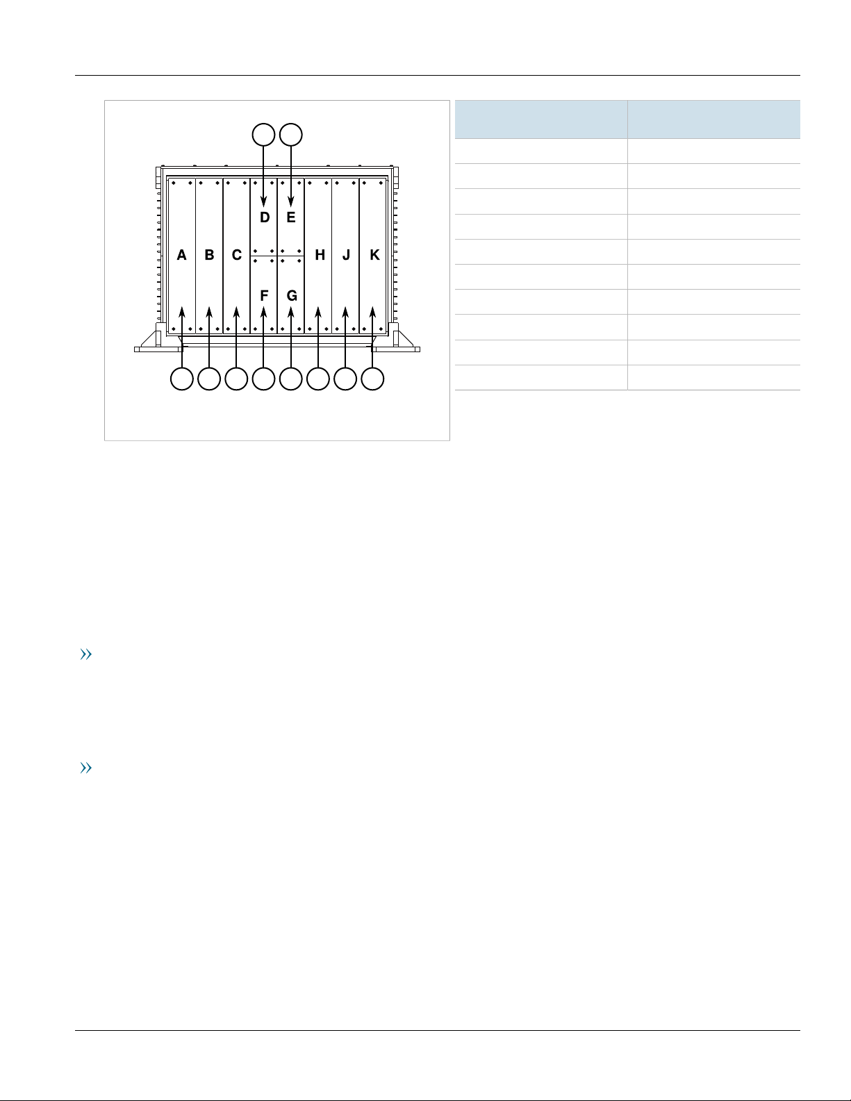
Every module slot in the RUGGEDCOM MX5000RE chassis is connected to a patch panel assembly in the enclosure.
Patch panels are provided pre-assembled with the appropriate ports and wiring to make installation quick and
simple.
The following maps the patch panels to their associated line module slot in the RUGGEDCOM MX5000RE chassis.
6 Supported Fiber Optic Cables
Page 17
RUGGEDCOM MX5000RE
B
D
E
A
CGF
H
I J
Installation Guide
Chapter 1
Introduction
Patch Panel
A LM1
B LM2
C LM3
D CM
E PM1
F SM
G PM2
H LM4
I LM5
J LM6
Figure4:Patch Panels
RUGGEDCOM
MX5000RE Module Slot
For information about how to install patch panels, refer to Section2.11, “Installing the Patch Panels”.
Section1.6
Decommissioning and Disposal
Proper decomissioning and disposal of this device is important to prevent malicious users from obtaining
proprietary information and to protect the environment.
Decommissioning
This device may include sensitive, proprietary data. Before taking the device out of service, either permanently or
for maintenance by a third-party, make sure it has been fully decommissioned.
For more information, refer to the associated User Guide.
Recycling and Disposal
For environmentally friendly recycling and disposal of this device and related accessories, contact a facility
certified to dispose of waste electrical and electronic equipment. Recycling and disposal must be done in
accordance with local regulations.
Decommissioning and Disposal 7
Page 18

Chapter 1
Introduction
RUGGEDCOM MX5000RE
Installation Guide
8 Decommissioning and Disposal
Page 19
RUGGEDCOM MX5000RE
Installation Guide
Installing the Device
Installing the Device
The following sections describe how to install the device, including mounting the device, connecting power, and
connecting the device to the network.
DANGER!
Electrocution hazard – risk of serious personal injury and/or damage to equipment. Before performing
any maintenance tasks, make sure all power to the device has been disconnected and wait
approximately two minutes for any remaining energy to dissipate.
WARNING!
Burn hazard – risk of serious personal injury. Avoid contact with the surface of the unit. The metal
surface may be hot due to the high allowable ambient temperature per specification.
Éviter tout contact avec la surface. La surface métallique peut être chaude a cause d'une température
ambiante élevée selon les spécifications. S.V.P. se référer à la version française de ce guide pour les
détails.
Chapter 2
WARNING!
Radiation hazard – risk of serious personal injury. This product contains a laser system and is classified
as a CLASS 1 LASER PRODUCT. Use of controls or adjustments or performance of procedures other
than those specified herein may result in hazardous radiation exposure.
IMPORTANT!
This product contains no user-serviceable parts. Attempted service by unauthorized personnel shall
render all warranties null and void.
Changes or modifications not expressly approved by Siemens Canada Ltd could invalidate
specifications, test results, and agency approvals, and void the user's authority to operate the
equipment.
IMPORTANT!
This product should be installed in a restricted access location where access can only be gained by
authorized personnel who have been informed of the restrictions and any precautions that must be
taken. Access must only be possible through the use of a tool, lock and key, or other means of security,
and controlled by the authority responsible for the location.
CONTENTS
• Section2.1, “General Procedure”
• Section2.2, “Unpacking the Device”
• Section2.3, “Installing the Power Supply Patch Cables”
• Section2.4, “Installing the Chassis Ground Connection”
• Section2.5, “Connecting the Failsafe Alarm Relay”
9
Page 20

Chapter 2
Installing the Device
• Section2.6, “Installing the Fan Tray Cables”
• Section2.7, “Installing the Mounting Brackets”
• Section2.8, “Installing the EMI Gaskets”
• Section2.9, “Assembling the RUGGEDCOM MX5000 and RUGGEDCOM MX5000RE”
• Section2.10, “Installing the Fan Tray”
• Section2.11, “Installing the Patch Panels”
• Section2.12, “Connecting the Network Cables”
• Section2.13, “Installing the Front Panel”
• Section2.14, “Mounting the RUGGEDCOM MX5000RE”
• Section2.15, “Connecting Power”
Section2.1
General Procedure
The general procedure for installing the device is as follows:
RUGGEDCOM MX5000RE
Installation Guide
IMPORTANT!
The user is responsible for the operating environment of the device, including maintaining the integrity
of all protective conductor connections and checking equipment ratings. Make sure to review all
operating and installation instructions before commissioning or performing maintenance on the
device.
1. Review the relevant certification information for any regulatory requirements. For more information, refer to
Section6.1, “Approvals”.
2. Review the RUGGEDCOM MX5000RE Modules Catalog [https://support.industry.siemens.com/cs/ca/en/
view/109748481] for special installation or regulatory requirements related to the modules installed in the
device.
3. Install the power supply patch cables.
4. If necessary, install the RUGGEDCOM MX5000 chassis ground connection.
5. Connect the failsafe relay and connect the patch cables.
6. Install the fan tray cables.
7. Install the mounting brackets.
8. Install the EMI gaskets.
9. Assemble the RUGGEDCOM MX5000 with the enclosure.
10. Install the fan tray.
11. Install the patch panels.
12. Connect network cables to the patch panels.
13. Install the front panel.
14. Mount the RUGGEDCOM MX5000RE.
15. Connect power to the device and ground the device to safety Earth.
16. Connect the device to the network.
10 General Procedure
Page 21

RUGGEDCOM MX5000RE
Installation Guide
17. Configure the device.
Section2.2
Unpacking the Device
When unpacking the device, do the following:
1. Inspect the package for damage before opening it.
2. Visually inspect each item in the package for any physical damage.
3. Verify all items are included.
IMPORTANT!
If any item is missing or damaged, contact Siemens for assistance.
Section2.3
Installing the Device
Chapter 2
Installing the Power Supply Patch Cables
To connect the power supply patch cables to the enclosure, do the following:
1. Remove the screws from the outer safety cover.
Unpacking the Device 11
Page 22

Chapter 2
9
4
1
2
3
8
75 6
Installing the Device
RUGGEDCOM MX5000RE
Installation Guide
Figure5:Power Supply Patch Cable Connections
1.#6-32×3/8" Pan Head Screw 2.Outer Safety Cover 3.Inner Safety Cover 4.PS1 Cable Assembly 5.Terminal Lug Screws
6.Terminal Ring Lug 7.Terminal Block 8.MX5000 9.PS2 Cable Assembly
2. Remove the outer safety cover and the inner safety cover from the RUGGEDCOM MX5000.
3. Remove the three terminal lug screws from the terminal block.
DANGER!
Electrocution hazard – risk of death, serious personal injury and/or damage to the device. Make
sure the supplied cover is always installed over high voltage screw-type terminal blocks.
CAUTION!
Electrical hazard – risk of damage to equipment. Do not connect AC power cables to a DC power
supply terminal block. Damage to the power supply may occur.
4. Connect the live (+/L) lug from the PS1 cable assembly to the live terminal on the PS1 terminal block.
12 Installing the Power Supply Patch Cables
Page 23

RUGGEDCOM MX5000RE
1
2
3
1
2
3
Installation Guide
Figure6:AC Terminal Block Wiring
1.Live Terminal 2.Ground Terminal 3.Neutral Terminal
Installing the Device
Chapter 2
Figure7:DC Terminal Block Wiring
1.Live Terminal 2.Ground Terminal 3.Neutral Terminal
5. Connect the neutral (-/N) lug from the PS1 cable assembly to the neutral terminal on the PS1 terminal block.
IMPORTANT!
If the ground terminals are not connected to safety Earth, the chassis ground connection must be
connected. For more information, refer to Section2.4, “Installing the Chassis Ground Connection”.
6. Connect the ground (GND) lug from the PS1 cable assembly to the ground terminal on the PS1 terminal block.
7. If necessary, repeat Step 4 to Step 6 to connect the PS2 cable assembly.
8. Install the inner and outer safety covers, making sure the cables pass through the openings in the sides of the
covers.
9. Secure the inner and outer supply safety covers with the screws removed in Step 1.
Section2.4
Installing the Chassis Ground Connection
If the ground terminal on the power supply module(s) is not connected to safety Earth, a connection must be
provided from the chassis ground terminal on the RUGGEDCOM MX5000 chassis.
Installing the Chassis Ground Connection 13
Page 24

Chapter 2
3
2
1
Installing the Device
IMPORTANT!
If the ground terminal on the power supply module(s) is connected to safety Earth, a connection from
the chassis ground terminal is not required.
1. Position the grounding cable and external tooth lock washer on the RUGGEDCOM MX5000.
RUGGEDCOM MX5000RE
Installation Guide
Figure8:Chassis Ground Cable Assembly
1.External Tooth Lock Washer 2.#8-32×5/16" Pan Head Screw 3.Grounding Cable
2. Secure the grounding cable and external tooth lock washer to the RUGGEDCOM MX5000 with one pan head
screw. Torque the screw to 3.4 N·m (30 lbf·in).
NOTE
The other end of the grounding cable will be connected to the inside of the enclosure in later
Section2.5
Connecting the Failsafe Alarm Relay
The failsafe relay on the Control Module (CM) can be configured to latch based on alarm conditions. The NO
(Normally Open) contact is closed when the unit is powered and there are no active alarms. If the device is not
powered or if an active alarm is configured, the relay opens the NO contact and closes the NC (Normally Closed)
contact.
14 Connecting the Failsafe Alarm Relay
steps.
Page 25

RUGGEDCOM MX5000RE
21 3
Installation Guide
Pin Function
NC Normally Closed
Common Ground
NO Normally Open
Installing the Device
Figure9:Failsafe Alarm Relay Wiring
1.Normally Open 2.Common (Ground) 3.Normally Closed
The failsafe relay terminal is connected to the patch panel for the CM using the cable assembly provided. The
connector is an Amphenol MIL-DTL 38999 size 13, code A. The following is the pin-out for the connector:
Pin Description
Chapter 2
Figure10:Failsafe Relay Alarm Panel Connector
Section2.6
Installing the Fan Tray Cables
1. Apply Loctite® 222 to the threads of the fan tray cable connector threads.
A COM (Common)
B NO (Normally Open)
C NC (Normally Closed)
D Spare
Installing the Fan Tray Cables 15
Page 26

Chapter 2
1
Installing the Device
RUGGEDCOM MX5000RE
Installation Guide
Figure11:Fan Tray Cable Connections
1.Fan Cables
2. Attach two fan cables to the terminals on the rear of the RUGGEDCOM MX5000.
3. Using two cable ties, secure the fan cables and power cables to the cable tie base on the rear of the
RUGGEDCOM MX5000. Make sure the cable ties are snug and the cables are unable to slide freely.
16 Installing the Fan Tray Cables
Page 27

RUGGEDCOM MX5000RE
1
Installation Guide
Installing the Device
Chapter 2
Figure12:Power and Fan Tray Cable Ties
1.Cable Ties
4. After tightening the cable ties, trim and remove any excess length.
Section2.7
Installing the Mounting Brackets
1. Position one of the mounting brackets on one side of the RUGGEDCOM MX5000.
Installing the Mounting Brackets 17
Page 28

Chapter 2
2
1
Installing the Device
Figure13:Mounting Brackets
1.Mounting Bracket 2.#10-32×1/2" Flat Head Hex Socket Screw
RUGGEDCOM MX5000RE
Installation Guide
2. Secure the mounting bracket with 20 flat head hex socket screws. Hand tighten each screw and make sure
each screw head is flush with the surface of the mounting bracket.
3. Repeat Step 1 and Step 2 for the mounting bracket on the opposite side of the RUGGEDCOM MX5000.
Section2.8
Installing the EMI Gaskets
The material for the EMI (Electro-Magnetic Interference) gaskets is provided in two lengths for the two different
sizes of patch panel openings in the RUGGEDCOM MX5000:
EMI Gasket Material Length Patch Panel Opening
19.5" D, E, F and G
35.5" A, B, C, H, J and K
To install the EMI gaskets, do the following:
1. Make sure the groove surrounding each panel opening is free of dust, dirt or liquid.
2. Inspect each gasket for signs of twisting, cracking, wear or damage. If the gaskets need to be replaced, cut
and discard the them.
IMPORTANT!
• Do not stretch the gasket material. Stretching the gasket material will degrade performance. If
gasket material is inadvertently stretched, remove it from the patch panel groove and allow it to
sit for 8 hours before attempting to install it again. The material will return to its original length.
• Do not cut the gasket to length before assembly.
18 Installing the EMI Gaskets
Page 29

RUGGEDCOM MX5000RE
2
1
Installation Guide
3. Starting at the overlapping section of a patch panel groove, gently press a length of gasket material into the
groove. Work around the groove until the gasket is seated all around the opening and in the overlapping
section. Make sure the gasket material is loose and is not stretched during installation.
Installing the Device
Chapter 2
Figure14:EMI Gasket Installation
4. Trim the gasket material to length.
5. Repeat Step 3 and Step 4 for each patch panel opening.
Section2.9
Assembling the RUGGEDCOM MX5000 and RUGGEDCOM MX5000RE
To install the RUGGEDCOM MX5000 in the RUGGEDCOM MX5000RE, do the following:
1. Position the RUGGEDCOM MX5000RE with the front opening facing up.
Assembling the RUGGEDCOM MX5000 and RUGGEDCOM
MX5000RE 19
Page 30

Chapter 2
1
2
3
4
5
6
8 9
7
Installing the Device
RUGGEDCOM MX5000RE
Installation Guide
Figure15:MX5000 and RUGGEDCOM MX5000RE Assembly
1.#10-32×1" Screw 2.#10 Split Lockwasher 3.#10 Flat Washers 4.Grounding Cable 5.#10 Exterior Tooth Lockwasher
6.#10-32 Hex Nut 7.Power Supply Cable Assemblies 8.#6-32×3/8" SS304 Truss Head Philips Drive Screw 9.Inside Grounding
Stud
WARNING!
Crushing hazard – risk of serious injury or damage to equipment. Make sure the device is properly
supported at all times. It is highly recommended to employee the assistance of another technician.
2. Have an assistant hold the attached cables and patch panel clear of the RUGGEDCOM MX5000RE sides.
3. Hold the RUGGEDCOM MX5000 by both mount bracket handles and lower it into the RUGGEDCOM
MX5000RE.
4. Lower the RUGGEDCOM MX5000 unit until the mount bracket flanges are supporting the unit on the inner
mount bracket surfaces. If the RUGGEDCOM MX5000 does not lower far enough, make sure the support pins
on the back of the mount brackets are properly aligned with the alignment holes inside the RUGGEDCOM
MX5000RE.
5. Secure the RUGGEDCOM MX5000 to the RUGGEDCOM MX5000RE using 18 screws, flat washers and split
lockwashers. Make sure each screw is assembled with two flat washers, one split lockwasher and then the
screw.
20
Assembling the RUGGEDCOM MX5000 and RUGGEDCOM
MX5000RE
Page 31

RUGGEDCOM MX5000RE
1
2
Installation Guide
Installing the Device
6. Place one exterior tooth lockwasher on the inside grounding stud found on the right side of the RUGGEDCOM
MX5000RE.
7. Attach the free end of the grounding cable to the inside grounding stud using two hex nuts.
8. Carefully pass the PS1 power supply cable assembly through opening E on the bottom of the RUGGEDCOM
MX5000RE.
9. Carefully pass the PS2 power supply cable assembly through opening G on the bottom of the RUGGEDCOM
MX5000RE.
NOTE
When aligning the patch panels, the inside grounding stud should be toward the back of the
RUGGEDCOM MX5000RE.
10. Apply Loctite® 242 to four SS304 truss head philips drive screws.
11. Secure both patch panels to the RUGGEDCOM MX5000RE with four SS304 truss head philips drive screws.
Section2.10
Installing the Fan Tray
Chapter 2
To intall the fan tray, do the following:
1. Position the fan tray the DB25 connectors facing forward when the fan tray is in the RUGGEDCOM MX5000RE.
Figure16:Fan Tray Installation
1.#8-32×5/16" Pan Head Screw 2.Fan Tray
Installing the Fan Tray 21
Page 32

Chapter 2
1
Installing the Device
RUGGEDCOM MX5000RE
Installation Guide
2. Align the fan tray with the pins on the bottom of the internal mounting brackets inside the RUGGEDCOM
MX5000RE.
3. Slide the fan tray onto the locating pins until the fan tray mount brackets touch the RUGGEDCOM MX5000RE
inner mount brackets.
4. Secure the fan tray using six (6) screws. Use Loctite® 242 on all screws.
5. Take the free ends of the fan control cables and straighten the cables side by side.
6. Take the right side fan control cable and thread it through the three (3) loops on the left side of the fan tray.
7. Connect the fan control cable to the left side DB25 connector.
8. Repeat Step 6 and Step 7 using the left side fan control cable.
9. Apply Loctite® 222 on the DB25 plug screws. Tighten the DB25 connector screws moderately.
Figure17:Fan Tray Cable Clips
1.Cable Clip
10. Secure the cables using two (2) cable ties through the slots on the outermost cable clips on the fan tray. Make
sure the cables are held snug and are unable to slide freely.
11. After tightening the cable ties, trim and remove any excess length.
22 Installing the Fan Tray
Page 33

RUGGEDCOM MX5000RE
1
2
Installation Guide
Section2.11
Installing the Device
Installing the Patch Panels
To install a patch panel, do the following:
NOTE
The following procedure also applies for blank patch panels.
1. From the bottom of the enclosure, feed the patch panel cables through the appropriate opening. For more
information about which patch panels correspond to which openings, refer to Section1.5, “Patch Panels”.
Chapter 2
Figure18:Patch Panel Installation
1.#6-32×5/8" SS304 Truss Head Philips Drive Screw 2.Patch Panel
2. Align the patch panel with the screw holes surrounding the patch panel opening.
3. Apply Loctite® 242 to each screw.
4. Secure the patch panel to the enclosure with eight (8) screws for large panels, or four (4) for small panels.
Hand-tighten the screws evenly in a cross pattern. There should be no visible gap between the patch panel
Installing the Patch Panels 23
Page 34

Chapter 2
Installing the Device
and the enclosure's bottom plate when properly tightened. Pay careful attention to avoid damaging the
cables and gaskets.
Section2.12
RUGGEDCOM MX5000RE
Installation Guide
Connecting the Network Cables
To connect network cables to the patch panels, do the following for each patch panel:
Connecting Micro-D Cables
1. Connect each cable in the patch panel bundle to the appropriate port. Make sure the cable and port have
identical numbers.
2. Secure the bundled cables to an available cable tie base using one (1) cable tie. Tighten the cable tie until the
bundled cables are held securely.
3. Install additional cable ties where necessary.
Connecting Ethernet Cables
1. Carefully remove the dust caps from one connector at a time.
2. Insert the uncapped connector into the appropriate transceiver on the RUGGEDCOM MX5000. Make sure the
cable and port have the same number, and the transmit and receive fibers are plugged in to the correct side
of the transceiver.
3. Repeat Step 1 and Step 2 for all remaining fiber cables.
4. Secure all fiber cables with the provided Velcro® straps. Wrap the Velcro® cable strap around the fiber cables
tightly, making sure the fiber cables are held securely.
Section2.13
Installing the Front Panel
To install the front panel for the RUGGEDCOM MX5000RE, do the following:
1. Position the RUGGEDCOM MX5000RE with the front opening facing up.
24 Connecting the Network Cables
Page 35

RUGGEDCOM MX5000RE
Installation Guide
Installing the Device
Chapter 2
Figure19:Front Panel Installation
WARNING!
Crushing hazard – risk of serious injury or damage to equipment. Make sure the front panel is
properly supported at all times. It is highly recommended to employee the assistance of another
technician.
2. Position the front panel over the RUGGEDCOM MX5000RE opening, aligning the panel with the two (2)
locating pins on the front face.
3. Secure the front panel with 24 screws. Hand-tighten the screws evenly in a cross pattern.
Section2.14
Mounting the RUGGEDCOM MX5000RE
To mount the fully assembled RUGGEDCOM MX5000RE to its final mounting surface, do the following:
1. Make sure the mounting surface is flat within a tolerance of 0.254 mm (0.010 in).
2. Position the enclosure with the lifting ring facing up.
Mounting the RUGGEDCOM MX5000RE 25
Page 36

Chapter 2
1
Installing the Device
Figure20:Mounting the RUGGEDCOM MX5000RE
1.Screw
RUGGEDCOM MX5000RE
Installation Guide
WARNING!
Crushing hazard – risk of serious injury or damage to equipment. Make sure the front panel is
properly supported at all times. It is highly recommended to employee the assistance of another
technician.
3. Secure the RUGGEDCOM MX5000RE to a wall or mounting bracket using screws. Torque each screw evenly to
61 N·m (45 lbf·ft) in a cross pattern.
Section2.15
Connecting Power
The RUGGEDCOM MX5000RE supports dual redundant AC and/or DC power modules that can be installed in any
combination.
The MX5000 is equipped with a screw-type terminal block, which provides power to both power modules. The
terminal block is installed using Philips screws and compression plates, allowing either bare wire connections or
crimped terminal lugs. Use #6 size ring lugs for secure, reliable connections under severe shock or vibration.
For information about installing or removing a power module, refer to Section4.3, “Installing/Removing Power
Supply Modules”.
DANGER!
Electrocution hazard – risk of serious personal injury or death. The device may have two power
modules equipped, which may be connected to separate power sources. Make sure all power sources
are off before servicing the power module terminals.
IMPORTANT!
• In an AC/DC power arrangement, the placement of the AC and DC power modules is not slotdependent. Either power module slot can be used for AC or DC power.
• For maximum redundancy in a dual power module configuration, use two independent power
sources.
26 Connecting Power
Page 37

RUGGEDCOM MX5000RE
Installation Guide
Installing the Device
• Use minimum #16 gage copper wiring when connecting terminal blocks.
• For 125/230 VAC rated equipment, an appropriately rated AC circuit breaker must be installed.
• For 125/250 VDC rated equipment, an appropriately rated DC circuit breaker must be installed.
• It is recommended to provide a separate circuit breaker for each power module module.
• Equipment must be installed according to applicable local wiring codes and standards.
CONTENTS
• Section2.15.1, “Connecting Power to the Enclosure”
Section2.15.1
Connecting Power to the Enclosure
To complete the power circuit, connect an external power supply to the PS1 and/or PS2 patch panels using male
Amphenol MIL-DTL 389999 size 13, code N connectors.
Pin Description
Chapter 2
Figure21:Power Supply Panel Connector
A PS LIve/+
B Spare
C PS Neutral/-
D Spare
Connecting Power to the Enclosure 27
Page 38

Chapter 2
Installing the Device
RUGGEDCOM MX5000RE
Installation Guide
28 Connecting Power to the Enclosure
Page 39

RUGGEDCOM MX5000RE
1
15
69
Installation Guide
Device Management
This section describes how to connect to and manage the device.
CONTENTS
• Section3.1, “Connecting to the Device”
• Section3.2, “Configuring the Device”
• Section3.3, “Accessing the CompactFlash Card”
Section3.1
Device Management
Chapter 3
Connecting to the Device
The following describes the various methods for accessing the RUGGEDCOM ROX II console and Web interfaces
on the device. For more detailed instructions, refer to the RUGGEDCOM ROX II User Guide for the RUGGEDCOM
MX5000RE.
Serial Console and Management Ports
Connect a PC or terminal directly to the serial console or management ports to access the boot-time control and
ROX II interfaces. The serial console port provides access to ROX II's console interface, while the management port
provides access to ROX II's console and Web interfaces.
IMPORTANT!
The serial console and management (MGMT) ports are intended to be used only as temporary
connections during initial configuration or troubleshooting.
The serial console port implements RS232 DCE (Data Communication Equipment) on a DB9 connector. The
following is the pin-out for the port:
Pin Name Description
1 DCD Data Carrier Detect
2 RX Receive Data
3 TX Transmit Data
4 DTR Data Terminal Ready
5 GND Signal Ground
6 DSR Data Set Ready
Figure22:Serial DB9 Console Port
Connecting to the Device 29
7 RTS Request to Send
8 CTS Clear To Send
Page 40

Chapter 3
1
8
Device Management
Pin Name Description
9 Reserved (Do Not Connect)
RUGGEDCOM MX5000RE
Installation Guide
The management port is a 10/100Base-TX copper Ethernet port with an RJ45 connector. The following is the pinout for the management port:
Pin Name Description
1 TX+ Transmit Data+
2 TX- Transmit Data-
3 RX+ Receive Data+
Figure23:RJ45 Management Port
4 Reserved (Do Not Connect)
5 Reserved (Do Not Connect)
6 RX- Receive Data-
7 Reserved (Do Not Connect)
8 Reserved (Do Not Connect)
Communication Ports
Connect any of the available Ethernet ports on the device to a management switch and access the RUGGEDCOM
ROX II console and Web interfaces via the device's IP address. The factory default IP address for the RUGGEDCOM
MX5000RE is https://192.168.0.2.
For more information about available ports, refer to Chapter4, Modules.
Section3.2
Configuring the Device
Once the device is installed and connected to the network, it must be configured. All configuration management
is done via the RUGGEDCOM ROX II interface. For more information about configuring the device, refer to the
RUGGEDCOM ROX II User Guide associated with the installed software release.
Section3.3
Accessing the CompactFlash Card
The RUGGEDCOM MX5000RE features a removable CompactFlash (CF) card that stores configuration files,
firmware (active and backup versions), file-based feature keys and other system files.
CAUTION!
Configuration hazard – risk of data corruption/loss. Do not remove or insert the CF card when the
device is powered on.
The CF card should only be removed in the following scenarios:
• The chassis is defective (with the exception of power and media modules)
30 Configuring the Device
Page 41

RUGGEDCOM MX5000RE
2
1
Installation Guide
Device Management
• The CF card is deemed defective or corrupt
• The device is rendered non-functional due to a serious configuration error, data corruption, or hardware fault
CAUTION!
Configuration hazard – risk of data corruption/loss. The following will void the warranty and
potentially result in configuration data corruption/loss:
• Using a CF card not approved by Siemens for use with this device
• Removing the CF card in any scenario other than those described in this section
Inserting the CF card
To insert the CF card into the device, do the following:
IMPORTANT!
The device should only be powered on when the CF card is present.
1. Make sure the device is powered down.
2. Remove the CF card access panel.
3. Insert the CF card into the slot until it is fully seated.
Chapter 3
Figure24:Inserting the CF Card
1.CompactFlash Card 2.Access Panel
4. Secure the CF card access panel to the chassis.
Removing the CF card
To remove the CF card from the device, do the following:
1. Make sure the device is powered down.
2. Remove the CF card access panel.
Accessing the CompactFlash Card 31
Page 42

Chapter 3
3
2
1
Device Management
Figure25:Removing the CF Card
1.Ejector Button 2.CompactFlash Card 3.Access Panel
RUGGEDCOM MX5000RE
Installation Guide
3. Press the ejector button to the left of the CF card and then pull the card out.
4. Secure the CF card access panel to the chassis.
32 Accessing the CompactFlash Card
Page 43

RUGGEDCOM MX5000RE
2
3
4
6 7 8 9
1
5
10
Installation Guide
Modules
The RUGGEDCOM RUGGEDCOM MX5000 features slots for up to two power modules and eight line modules,
which can be used to expand and customize the capabilities of the device to suit specific applications. A variety of
modules are available, each featuring a specific type of communication port: copper Ethernet, fiber optic Ethernet,
SFP or serial.
Two slots are reserved for one control module (required) and one switch module (optional).
All modules are field-replaceable.
Use the RUGGEDCOM ROX II software to determine which ports are equipped on the device. For more information,
refer to the RUGGEDCOM ROX II User Guide for the device.
NOTE
Switch modules are only compatible with 8-port fiber optic Ethernet modules.
Chapter 4
Modules
Figure26:Available Chassis Slots
1.Power Supply Module (PS1) 2.Ethernet Module Slot (LM1) 3.Ethernet Module Slot (LM2) 4.Ethernet Module Slot (LM3) 5.Control
Module (CM) 6.Switch Module (SM) 7.Ethernet Module Slot (LM4) 8.Ethernet Module Slot (LM5) 9.Ethernet Module Slot (LM6)
10.Power Supply Module (PS2)
CONTENTS
• Section4.1, “Available Modules”
• Section4.2, “Installing/Removing Line Modules”
• Section4.3, “Installing/Removing Power Supply Modules”
33
Page 44

Chapter 4
Modules
Section4.1
Available Modules
The following is a list of all power and line modules available for use in the RUGGEDCOM MX5000RE. For
more information about individual modules, refer to the RUGGEDCOM MX5000RE Modules Catalog [https://
support.industry.siemens.com/cs/ca/en/view/109748780].
Power Supply Modules
RUGGEDCOM MX5000RE
Installation Guide
RUGGEDCOM MX5000REPN PS MHIF Specifications
Input Range: 88 to 300 VDC or
85 to 264 VAC
Terminal Type: Terminal located
on chassis
Copper Ethernet Modules
RUGGEDCOM MX5000REPN LM M4CG02 Specifications
Ports: 4
Speed: 1000 Mbps
Interface: TX
Connector: Micro-D
RUGGEDCOM MX5000REPN LM M8TX02 Specifications
Ports: 8
Speed: 100 Mbps
Interface: TX
Connector: Micro-D
Article Numbers
6GK6050-0RL16-0AA1
Article Numbers
6GK6050-0ML20-0FD1 (Module)
6GK6050-0RL20-0FD1 (Module
with Patch Panel and Cables)
6GK6050-0AR00-4RD0 (Patch
Panel and Cables)
Article Numbers
6GK6050-0ML20-0ND1 (Module)
6GK6050-0RL20-0ND1 (Module
with Patch Panel and Cables)
6GK6050-0AR00-8RD0 (Patch
Panel and Cables)
RUGGEDCOM MX5000REPN LM M12TX01 Specifications
Ports: 12
Speed: 100 Mbps
Interface: TX
Connector: RJ45
Article Numbers
6GK6050-0ML20-0NB1 (Module)
6GK6050-0RL20-0NE1 (Module
with Patch Panel and Cables)
6GK6050-0AR00-6RR0 (Patch
Panel and Cables)
Fiber Optic Ethernet Modules
RUGGEDCOM MX5000REPN LM M8FX11 Specifications
Mode: MM
Speed: 100 Mbps
Interface: FX
Ports: 8
Connector: LC
Distance: 2 km (1.2 mi)
34 Available Modules
Article Numbers
6GK6050-0ML20-0BD1 (Module)
6GK6050-0RL20-0BD1 (Module
with Patch Panel and Cables)
6GK6050-0AR00-8MM0 (Patch
Panel and Cables)
Page 45

RUGGEDCOM MX5000RE
Installation Guide
Chapter 4
Modules
RUGGEDCOM MX5000REPN LM M4FX11 Specifications
Mode: MM
Speed: 100 Mbps
Interface: FX
Ports: 4
Connector: LC
Distance: 2 km (1.2 mi)
RUGGEDCOM MX5000REPN LM M4FG01 Specifications
Mode: MM
Speed: 1000 Mbps
Interface: SX
Wavelength: 850 nm
Ports: 4
Connector: LC
Distance: 500 m (1640 ft)
RUGGEDCOM MX5000REPN LM M4FG03 Specifications
Mode: SM
Speed: 1000 Mbps
Interface: LX
Wavelength: 1310 nm
Ports: 4
Connector: LC
Distance: 10 Km (6 mi)
Article Numbers
6GK6050-0ML20-0BH1 (Module)
6GK6050-0RL20-0BH1 (Module
with Patch Panel and Cables)
6GK6050-0AR00-4MM0 (Patch
Panel and Cables)
Article Numbers
6GK6050-0ML20-0BK1 (Module)
6GK6050-0RL20-0BK1 (Module
with Patch Panel and Cables)
6GK6050-0AR00-4MM0 (Patch
Panel and Cables)
Article Numbers
6GK6050-0ML20-0CR1 (Module)
6GK6050-0RL20-0CR1 (Module
with Patch Panel and Cables)
6GK6050-0AR00-4SM0 (Patch
Panel and Cables)
Serial Modules
RUGGEDCOM MX5000REPN LM MS01 Specifications
Standard: RS232/RS422/RS485
Ports: 8
Connector: DB9
Control Modules
RUGGEDCOM MX5000REPN MCM01 L3SEL3HW Specifications
Layer 3 Standard Edition, Layer 3
Hardware
Article Numbers
6GK6050-0ML20-0KB1 (Module)
6GK6050-0RL20-0KB1 (Module
with Patch Panel and Cables)
6GK6050-0AR00-8DR0 (Patch
Panel and Cables)
Article Numbers
6GK6050-0ML30-0BA1 (Module)
6GK6050-0RL30-0BA1 (Module
with Patch Panel and Cables)
6GK6050-0AR00-1CP0 (Patch
Panel and Cables)
Available Modules 35
Page 46

Chapter 4
Modules
RUGGEDCOM MX5000RE
Installation Guide
RUGGEDCOM MX5000REPN MCM01 L3SECL3HW Specifications
Layer 3 Security Edition, Layer 3
Hardware
Switch Modules
RUGGEDCOM MX5000REPN MSM36 Specifications
Mode: SM
Speed: 1000 Mbps
Interface: LX
Wavelength: 1310 nm
Ports: 2
Connector: LC
Distance: 10 Km (6 mi)
RUGGEDCOM MX5000REPN MSM61 Specifications
Layer 3
Article Numbers
6GK6050-0ML30-0CA1 (Module)
6GK6050-0RL30-0CA1 (Module
with Patch Panel and Cables)
6GK6050-0AR00-1CP0 (Patch
Panel and Cables)
Article Numbers
6GK6050-0ML40-0RA1 (Module)
6GK6050-0RL40-0RA1 (Module
with Patch Panel and Cables)
6GK6050-0AR00-1SP0 (Patch
Panel and Cables)
Article Numbers
6GK6050-0ML40-0VA1 (Module)
6GK6050-0RL40-0VA1 (Module
with Patch Panel and Cables)
6GK6050-0AR00-0XF0 (Patch
Panel and Cables)
RUGGEDCOM MX5000REPN MSM70 Specifications
Mode: SM
Speed: 10 Gbps
Interface: LR
Wavelength: 1310nm
Ports: 2
Connector: LC
Distance: 10km (6mi)
Network Redundancy Modules
RUGGEDCOM MX5000REPN LM MPRP Specifications
Ports: 2
Speed: 1000 Mbps
Interface: LX
Port Type: RJ45
Distance: 10 km (6.2 mi)
Protocol: PRP
Article Numbers
6GK6050-0ML40-0XA1 (Module)
6GK6050-0RL40-0WA1 (Module
with Patch Panel and Cables)
6GK6050-0AR00-1SP0 (Patch
Panel and Cables)
Article Numbers
6GK6050-0ML20-0PR1 (Module)
6GK6050-0RL20-0PR1 (Module
with Patch Panel and Cables)
6GK6050-0AR00-2PR0 (Patch
Panel and Cables)
36 Available Modules
Page 47

RUGGEDCOM MX5000RE
1
2
3
5 6 7 8
4
Installation Guide
Blank Modules
Chapter 4
Modules
RUGGEDCOM MX5000REPN PS XX Specifications
Blank power supply module, full
panel
RUGGEDCOM MX5000REPN LM XX Specifications
Blank line module, half panel
Section4.2
Article Numbers
6GK6050-0RL10-0AA1
Article Numbers
6GK6050-0RL20-0AA1
Installing/Removing Line Modules
Upon installing a new line module in the device, all features associated with the module are available in
RUGGEDCOM ROX II. For more information, refer to the RUGGEDCOM ROX II User Guide for the RUGGEDCOM
MX5000RE.
Once a line module is removed, all the features associated with the module are hidden or disabled in RUGGEDCOM
ROX II.
Figure27:Line Modules
1.Ethernet Module Slot (LM1) 2.Ethernet Module Slot (LM2) 3.Ethernet Module Slot (LM3) 4.Control Module (CM) 5.Switch
Module (SM) 6.Ethernet Module Slot (LM4) 7.Ethernet Module Slot (LM5) 8.Ethernet Module Slot (LM6)
CAUTION!
Contamination hazard – risk of equipment damage. Prevent the ingress of water, dirts and other debris
that may lead to premature equipment failure. Always make sure slots are not left empty and open
ports are protected with plugs or covers.
Installing/Removing Line Modules 37
Page 48

Chapter 4
1
2
3
Modules
NOTE
Control and switch modules are not hot swappable. Power to the device must be disconnected before
removing these modules.
Removing a Line Module
To remove a line module, do the following:
1. For Control and switch modules only, make sure power to the device has been disconnected and wait
approximately two minutes for any remaining energy to dissipate.
2. [Optional] If the device is installed in a rack, remove it from the rack.
3. Loosen the screws that secure the module.
4. Pull the module from the chassis to disconnect it.
RUGGEDCOM MX5000RE
Installation Guide
Figure28:Removing a Module
1.Chassis 2.Module 3.Screw
5. Install a new module or a blank module (to prevent the ingress of dust and dirt).
6. [Optional] If necessary, install the device in the rack.
7. For control and switch modules only, connect power to the device.
Installing a Line Module
To install a line module, do the following:
1. For Control and switch modules only, make sure power to the device has been disconnected and wait
approximately two minutes for any remaining energy to dissipate.
2. [Optional] If the device is installed in a rack, remove it from the rack.
3. Remove the current module from the slot.
4. Insert the new module into the slot.
38 Installing/Removing Line Modules
Page 49

RUGGEDCOM MX5000RE
1
2
3
1
2
Installation Guide
Figure29:Installing a Module
1.Chassis 2.Module 3.Screw
Chapter 4
Modules
5. Tighten the screws to secure the module.
6. [Optional] If necessary, install the device in the rack.
7. For control and switch modules only, connect power to the device.
Section4.3
Installing/Removing Power Supply Modules
The RUGGEDCOM MX5000 supports dual redundant power supplies that can be installed in any combination.
Figure30:Power Supply Modules
1.Power Supply Module (PS1) 2.Power Supply Module (PS2)
Installing/Removing Power Supply Modules 39
Page 50

Chapter 4
3
2
1
Modules
CAUTION!
Contamination hazard – risk of equipment damage. Prevent the ingress of water, dirts and other debris
that may lead to premature equipment failure. Always make sure slots are not left empty.
NOTE
Power modules are hot swappable. When installing/removing a power module, it is not necessary to
turn off power to the device.
Removing a Power Supply Module
To remove a power module, do the following:
1. Loosen the screws that secure the module to the chassis until the module can be removed.
RUGGEDCOM MX5000RE
Installation Guide
Figure31:Removing a Power Supply
1.Screws 2.Power Supply 3.Chassis
2. Slide the module out of the chassis.
3. Install a new or blank module to prevent the ingress of dust and dirt.
Installing a Power Supply Module
To install a power module, do the following:
1. If equipped, remove the existing module.
2. Insert the module into the empty slot.
40 Installing/Removing Power Supply Modules
Page 51

RUGGEDCOM MX5000RE
3
2
1
Installation Guide
Figure32:Installing a Power Supply Module
1.Screws 2.Power Supply 3.Chassis
3. Hand-tighten the screws to secure the power module to the chassis.
4. Turn on power to the device and confirm the module is receiving and supplying power. This is indicated by
the LEDs on the module.
Chapter 4
Modules
LED State Description
O Green The module is supplying power
I Green The module is receiving power
Installing/Removing Power Supply Modules 41
Page 52

Chapter 4
Modules
RUGGEDCOM MX5000RE
Installation Guide
42 Installing/Removing Power Supply Modules
Page 53

RUGGEDCOM MX5000RE
Installation Guide
Technical Specifications
This section provides important technical specifications related to the device and available modules.
CONTENTS
• Section5.1, “Power Supply Specifications”
• Section5.2, “Failsafe Relay Specifications”
• Section5.3, “Operating Environment”
• Section5.4, “Mechanical Specifications”
• Section5.5, “Dimension Drawings”
Technical Specifications
Chapter 5
Section5.1
Power Supply Specifications
Power Supply Type
HI (125/250 VDC)
HI (110/230 VAC)
a
Power consumption varies based on the device configuration. Each 10/100Base-Tx port consumes roughly 1 W less than a fiber optic port.
b
The HI power supply is the same power supply for both AC and DC.
c
(T) denotes time-delay fuse. Internal fuse is not user-replaceable.
d
Rating at 85 °C (185 °F) ambient temperature at worst-case load.
b
b
Min Max
88 VDC 300 VDC
85 VAC 264 VAC
Section5.2
Input Range
Internal Fuse Rating
6.3 A, 250 V(T)
Failsafe Relay Specifications
Maximum Switching Voltage Rated Switching Current Isolation
30 VDC 2 A, 60 W
Max. Power
Consumption
c
110 W
a
d
125 VDC 0.24 A, 30 W
125 VAC 0.5 A, 62.5 W
220 VDC 0.24 A, 60 W
250 VAC 0.25 A, 62.5 W
1500 V
for 1 minute
rms
Power Supply Specifications 43
Page 54

Chapter 5
Technical Specifications
Section5.3
Operating Environment
The RUGGEDCOM MX5000RE is rated to operate under the following environmental conditions.
Ambient Operating Temperature
Ambient Storage Temperature -40 to 85 °C (-40 to 185 °F)
Ambient Relative Humidity
Maximum Altitude 2000 m (6562 ft)
e
Measured from a 30 cm (12 in) radius surrounding the center of the enclosure.
f
Operating temperature may vary based on the limitations of installed SFPs. Refer to the RUGGEDCOM SFP Transceivers Catalog for SFP temperature ratings.
g
Non-condensing.
Section5.4
ef
g
-40 to 85 °C (-40 to 185 °F)
5% to 95%
Mechanical Specifications
RUGGEDCOM MX5000RE
Installation Guide
Weight (MX5000) 14-16 kg (30-35 lbs)
Weight (Enclosure) 68 kg (150 lbs)
Ingress Protection IP64
Chassis Material (MX5000) Aluminum
Chassis Material (Enclosure) Aluminum Alloy
Section5.5
Dimension Drawings
NOTE
All dimensions are in millimeters, unless otherwise stated.
44 Operating Environment
Page 55

RUGGEDCOM MX5000RE
Ø 9.65
48.26
71.12
76.20
619.25
76.20
444.50
492.25
625.60
746.25
317.50
458.98
571.50
12.70
71.12
50.80
484.12
Installation Guide
Technical Specifications
Chapter 5
Figure33:Overall Dimensions
Dimension Drawings 45
Page 56

Chapter 5
Technical Specifications
RUGGEDCOM MX5000RE
Installation Guide
46 Dimension Drawings
Page 57

RUGGEDCOM MX5000RE
Installation Guide
Certification
The RUGGEDCOM MX5000RE device has been thoroughly tested to guarantee its conformance with recognized
standards and has received approval from recognized regulatory agencies.
CONTENTS
• Section6.1, “Approvals”
• Section6.2, “MIL-STD Ratings”
• Section6.3, “EMC and Environmental Type Tests”
Section6.1
Chapter 6
Certification
Approvals
The following sections detail the approvals issued for the RUGGEDCOM MX5000RE.
CONTENTS
• Section6.1.1, “TÜV SÜD”
• Section6.1.2, “European Commission (EC)”
• Section6.1.3, “FCC”
• Section6.1.4, “FDA/CDRH”
• Section6.1.5, “ISED”
• Section6.1.6, “ISO”
• Section6.1.7, “RoHS”
• Section6.1.8, “Other Approvals”
Section6.1.1
TÜV SÜD
This device is certified by TÜV SÜD to meet the requirements of the following standards:
• CAN/CSA-C22.2 NO. 60950-1-07 (R2012)
Information Technology Equipment – Safety – Part 1: General Requirements (Bi-National standard, with UL
60950-1)
• UL 60950-1
Information Technology Equipment – Safety – Part 1: General Requirements)
Approvals 47
Page 58

Chapter 6
Certification
Section6.1.2
RUGGEDCOM MX5000RE
Installation Guide
European Commission (EC)
This device is declared by Siemens Canada Ltd to comply with essential requirements and other relevant provisions
of the following EC directives:
• EN 60950-1
Information Technology Equipment – Safety – Part 1: General Requirements
• EN 61000-6-2
Electromagnetic Compatibility (EMC) – Part 6-2: Generic Standards – Immunity for Industrial Environments
• EN 60825-1
Safety of Laser Products – Equipment Classification and Requirements
• EN 55022
Information Technology Equipment – Radio disturbance characteristics – Limits and methods of measurement
• EN 50581
Technical Documentation for the Assessment of Electrical and Electronic Products with Respect to the Restriction
of Hazardous Substances
The device is marked with a CE marking and can be used throughout the European community.
A copy of the CE Declaration of Conformity is available from Siemens Canada Ltd. For contact information, refer to
“Contacting Siemens”.
Section6.1.3
FCC
This equipment has been tested and found to comply with the limits for a Class A digital device, pursuant to Part
15 of the FCC Rules. These limits are designed to provide reasonable protection against harmful interference when
the equipment is operated in a commercial environment.
This equipment generates, uses and can radiate radio frequency energy and, if not installed and used in
accordance with the instruction manual, may cause harmful interference to radio communications. Operation of
this equipment in a residential area is likely to cause harmful interference in which case the user will be required
to correct the interference on his own expense.
Section6.1.4
FDA/CDRH
This device meets the requirements of the following U.S. Food and Drug Administration (FDA) standard:
• Title 21 Code of Federal Regulations (CFR) – Chapter I – Sub-chapter J – Radiological Health
48 European Commission (EC)
Page 59

RUGGEDCOM MX5000RE
Installation Guide
Section6.1.5
ISED
This device is declared by Siemens Canada Ltd to meet the requirements of the following ISED (Innovation Science
and Economic Development Canada) standard:
• CAN ICES-3 (A)/NMB-3 (A)
Section6.1.6
ISO
This device was designed and manufactured using a certified ISO (International Organization for Standardization)
quality program that adheres to the following standard:
• ISO 9001:2015
Quality management systems – Requirements
Section6.1.7
Chapter 6
Certification
RoHS
This device is declared by Siemens Canada Ltd to meet the requirements of the following RoHS (Restriction of
Hazardous Substances) directives for the restricted use of certain hazardous substances in electrical and electronic
equipment:
• China RoHS 2
Administrative Measure on the Control of Pollution Caused by Electronic Information Products
A copy of the Material Declaration is available online at https://support.industry.siemens.com/cs/ww/en/
view/109738831.
Section6.1.8
Other Approvals
This device meets the requirements of the following additional standards:
• IEEE 1613
IEEE Standard Environmental and Testing Requirements for Communications Networking Devices in Electric
Power Substations
• IEC 61850-3
Communications Networks and Systems for Power Utility Automation – Part 3: General Requirements
• IEC 61000-6-2
Electromagnetic Compatibility (EMC) – Part 6-2: Generic Standards – Immunity for Industrial Environments
ISED 49
Page 60

Chapter 6
Certification
Section6.2
MIL-STD Ratings
Standard Description Comments
MIL-STD 901D Shock (Hard-Mounted) Approved
MIL-STD 461 EMI Approved
DOD-STD 1399 Magnetic Field (DC Magnetic Exposure) Approved
RUGGEDCOM MX5000RE
Installation Guide
MIL-STD 1399 (Section 300B)
Electrical Power Interface
Standards for Shipboard Systems
Section6.3
EMC and Environmental Type Tests
The RUGGEDCOM MX5000RE has passed the following EMC and environmental tests.
IEC 61850-3 EMC Type Tests
Test Description Test Levels
IEC 61000-4-2 ESD
IEC 61000-4-3 Radiated RFI Enclosure Ports 20 V/m Note
IEC 61000-4-4 Burst (Fast Transient)
Enclosure Contact +/- 8 kV 4
Enclosure Air +/- 15 kV 4
Signal ports +/- 4 kV @ 2.5 kHz Note
DC Power ports +/- 4 kV 4
AC Power ports +/- 4 kV 4
Approved
Severity
Levels
a
a
Earth ground ports +/- 4 kV 4
Signal ports
IEC 61000-4-5 Surge
IEC 61000-4-6 Induced (Conducted) RFI
IEC 61000-4-8 Magnetic Field Enclosure Ports
DC Power ports
AC Power ports
Signal ports 10 V 3
D.C Power ports 10V 3
AC Power ports 10V 3
Earth ground ports 10V 3
+/- 4 kV line-to-earth,
+/- 2 kV line-to-line
+/- 2 kV line-to-earth,
+/- 1 kV line-to-line
+/- 4 kV line-to-earth,
+/- 2 kV line-to-line
100 A/m
1000 A/m for 1 s 5
4
3
4
50 MIL-STD Ratings
Page 61

RUGGEDCOM MX5000RE
Installation Guide
Chapter 6
Certification
Test Description Test Levels
IEC 61000-4-29 Voltage Dips & Interrupts
IEC 61000-4-11 Voltage Dips & Interrupts AC Power ports
IEC 61000-4-12 Damped Oscillatory
IEC 61000-4-16 Mains Frequency Voltage
IEC 61000-4-17 Ripple on DC Power Supply DC Power ports 10% 3
IEC 60255-5
DC Power ports
AC Power ports 30% for 1 period, 60% for 50 periods
Signal ports
DC Power ports
AC Power ports
Signal ports 30 V Continuous, 300 V for 1 s 4
DC Power ports 30 V Continuous, 300 V for 1 s 4
Signal ports 2 kV (Fail-Safe Relay output)
DC Power ports 2 kVDielectric Strength
AC Power ports 2 kV
Signal ports 5 kV (Fail-Safe Relay output)
30% for 0.1 s, 60% for
0.1 s, 100% for 0.05 s
100% for 5 periods,
100% for 50 periods
2.5 kV common, 1 kV
differential mode @1 MHz
2.5 kV common, 1 kV
differential mode @1MHz
2.5 kV common, 1 kV
differential mode @1MHz
Severity
Levels
3
3
3
HV Impulse
a
Siemens-specified severity levels
IEEE 1613 EMC Type Tests
NOTE
The RUGGEDCOM MX5000RE meets Class 2 requirements for an all-fiber configuration and Class 1
requirements for copper ports.
Description Test Levels
Radiated RFI Enclosure ports 35 V/m
Fast Transient
DC Power ports 5 kV
AC Power ports 5 kV
Enclosure Contact +/-2 kV, +/-4 kV, +/- 8 kVESD
Enclosure Air +/-4 kV, +/-8 kV, +/-15 kV
Signal ports +/- 4 kV @ 2.5 kHz
DC Power ports +/- 4 kV
AC Power ports +/- 4 kV
Earth ground ports +/- 4 kV
Signal ports 2.5 kV common mode @1 MHzOscillatory
DC Power ports 2.5 kV common, 1 kV differential mode @ 1 MHz
EMC and Environmental Type Tests 51
Page 62

Chapter 6
Certification
RUGGEDCOM MX5000RE
Installation Guide
Description Test Levels
AC Power ports 2.5 kV common, 1 kV differential mode @ 1 MHz
HV Impulse
Dielectric Strength
Signal ports 5 kV (Fail-Safe Relay output)
DC Power ports 5 kV
AC Power ports 5 kV
Signal ports 2 kV
DC Power ports 2 kV
AC Power ports 2 kV
Environmental Type Tests
Test Description Test Levels
IEC 60068-2-1 Cold Temperature Test Ad -40 °C (-40 °F), 16 Hours
IEC 60068-2-2 Dry Heat Test Bd 85 °C (185 °F), 16 Hours
IEC 60068-2-30 Humidity (Damp Heat, Cyclic) Test Db 95% (non-condensing), 55 °C (131 °F), 6 cycles
IEC 60255-21-1 Vibration 2 g @ 10 - 150 Hz
IEC 60255-21-2 Shock 30 g @ 11 mS
52 EMC and Environmental Type Tests
 Loading...