

Page 1
RUGGEDCOM
Operating Instructions
Release 07/2018
English
ANT1995-4MM
Antenna for global navigation satellite systems
RUGGEDCOM antennafor use in GPS, GLONASS and Galileo systems.
Order number: 6GK6000-8NS01-1AA0
For use with:
RUGGEDCOM RX1400
Copyright © Siemens Canada Limited 2016
All rights reserved
The reproduction, transmission or use of this document or its contents is not permitted without express written authority. Offenders
will be liable for damages. All rights, including rights created by
patent grant or registration of a utility model or design, are reserved.
Disclaimer of Liability
We have checked the contents of this manual for agreement with
the hardware and software described. Since deviations cannot be
precluded entirely, we cannot guarantee full agreement. However,
the data in this manual are reviewed regularly and any necessary
corrections included in subsequent editions. Suggestions for improvement are welcome.
Technical data subject to change without prior notice.
Siemens Canada Limited
Industry Sector
300 Applewood Crescent
Concord, Ontario
Canada, L4K 5C7
Classification of Safety-Related Notices
This manual contains notices which you should observe to ensure
your own personal safety, as well as to protect the product and
connected equipment. Notices relating to your personal safety are
highlighted by a warning triangle; notices relating to property damage only do not have a warning triangle. Warnings in descending
order according to the degree of danger are shown as follows.
Danger
indicates that death or severe personal injury will result if
proper precautions are not taken.
Warning
indicates that death or severe personal injury can result if
proper precautions are not taken.
Caution
with a warning triangle indicates that m
inor personal injury
can result if proper precautions are not taken.
Caution
without a warning triangle indicates that damage to pro
p-
erty can result if proper precautions are not taken.
Notice
indicates that an undesirable result or status can occur if
the relevant notice is ignored.
1 Overview
The ANT1995-4MM antenna is a compact multiband LTE MIMO and IEEE 802.11 antenna with
GPS/GLONASS. It is ideal for vehicles with limited
mounting space, as well as other machine-tomachine applications.
Features
Dual 4G LTE, IEEE 802.11 Wi-Fi and GPS L1/GLONASS
frequencies
Quick, easy installation/replacement
UV resistant housing
2 General safety notices
Warning
Devices installed outdoors must be within the area covered by a lightning protection system. Make sure all conducting systems entering from outdoors can be protected
by a lightning protection potential equalization system.
When implementing a lightning protection concept, make
sure to adhere to the VDE 0182 or IEC 62305 standard.
Warning
The device (a
nd its components) may only be used for the
application described in the catalog or operating instructions. It may only be combined with devices or components of other manufacturers that have been approved
and released by Siemens.
Correct and safe operation of the device is guaranteed
only when it is transported, stored, set up, installed, used
and maintained according to the recommendations.
3 Qualified personnel
Only qualified personnel should be allowed to install and
work on this equipment. Qualified persons in the sense of the
safety-related notices in this manual are defined as persons
who are authorized to commission, to ground, and to tag circuits, equipment, and systems in accordance with established safety practices and standards.
4 Components of the Product
The following components are supplied with the ANT19954MM:
1 x ANT1995-4MM Antenna
1 x Slotted lock nut
1 x Operating Instructions
Make sure the consignment received is complete. If it is not
complete or there are signs of external damage, contact the
supplier or a local Siemens office.
5 Recycling and Disposal
For environmentally friendly recycling and disposal of this accessory, contact a facility certified to dispose of waste electrical and electronic equipment. Disposal must be done in accordance with local regulations.
A5E39415407A-AA
Page 2
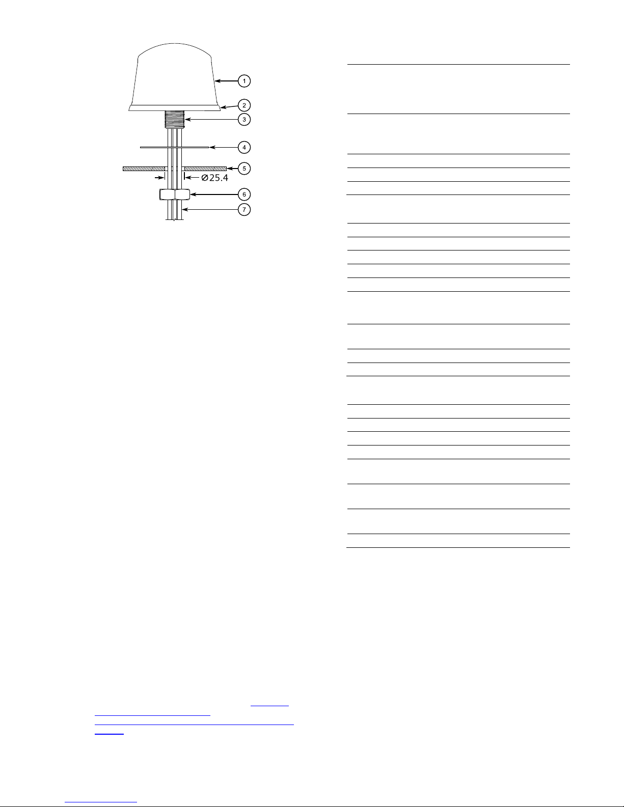
6 Installation
1. Select a mounting position that meets the following requirements:
The antenna can be centered on a ground plane
A minimum of 203 mm (8 in) of ground plane is avail-
able in all directions around the antenna
The antenna is positioned a minimum of 406 mm
(16 in) from adjacent antennae or metallic structures
A minimum area of 51 mm (2 in) is available on the
underside of the mounting surface to allow for torqueing and cable routing
2. Cut or drill a 25.4 mm (1 in) diameter hole through the
mounting the surface .
3. Remove all sharp edges from the mounting hole to prevent cable damage during installation.
4. Clean the mounting surface around the hole. Make sure
the surface is free of any debris that may prevent the VHB
foam gasket or outer rubber gasket from forming a proper
seal.
5. If installed, remove the slotted lock nut from the mounting stud .
6. Route the cables through the mounting hole, making
sure to not damage the jacket.
7. Remove the liner from the bonding tape on the underside of the antenna .
8. Align the mounting stud with the hole and press the antenna against the mounting surface.
9. Route the cables through the slotted lock nut.
10. Install the slotted lock nut on the mounting stud and hand
tighten.
11. Tighten the slotted lock nut until the antenna is fully seated, or tighten with a torque wrench to 8 N·m (6 lbf-ft).
12. Make sure the outer seal on the antenna is properly
seated and has formed a proper seal between the mounting surface and antenna.
13. Connect the cables to the associated RUGGEDCOM
RX1400. For more information, refer to the RUGGED-
COM RX1400 Installation Guide
[https://support.industry.siemens.com/cs/document/109
480955].
7 Technical Specifications
RF Antenna
Operating Frequency
4G LTE
698-960 MHz / 1710-2700
MHz
Wi-Fi 2.4-2.5 GHz / 4.9-5.9 GHz
Antenna G
ain (Typical)
4G LTE 2.5 dBi
Wi-Fi 3-4 dBi
Polarization Linear, vertical
Nominal Impedance 50 Ω
VSWR < 2.0:1
GNSS Antenna
Frequency Range 1565-1608 MHz
Amplifier Gain (Typical)
26 dB @ 3.0 VDC
Nominal Impedance 50 Ω
Output VSWR (Maximum) 2.0:1
Noise Figure (Typical) < 2.0 dB
Out-of-Band Rejection
f0 = 1586 MHz / f0 ± 50
MHz: ≥ 60 dBc / f0 ± 60
MHz: ≥ 70 dBc
Nominal Gain 3 dBic @ 90°
-2 dBic @ 20°
Polarization Right-hand circular
Horizontal Radiation Angle 360°
Environment/Mechanical
Connector N-Connector female
Weight 1.254 kg (2.765 lb)
Colour Black
Degree of Protection IP67
Storage Temperature -40 to 85 °C
(-40 to 185 °F)
Transport Temperature -40 to 85 °C
(-40 to 185 °F)
Operation Temperature -40 to 85 °C
(-40 to 185 °F)
RoHS 2011/65/EU Compliant
Page 3

8 Dimension Drawing
All dimensions are in millimeters (mm).
9 Radiation Patterns
LTE 850 MHz
LTE 1900 MHz
LTE 2600 MHz
Page 4

8 Radiation Patterns (Continued)
Wi-Fi 2450 MHz
Wi-Fi 5400 MHz
9 Customer Support
Customer support is available 24 hours, 7 days a week for all
Siemens customers. For technical support or general information, contact Siemens Customer Support through any of
the following methods:
Online
Visit http://www.siemens.com/automation/support-request
to submit a Support Request (SR) or check on the status
of an existing SR.
Telephone
Call a local hotline center to submit a Support Request
(SR). To locate a local hotline center, visit
http://www.automation.siemens.com/mcms/aspadb/en/automation-technology/Pages/default.aspx.
Mobile App
Install the Industry Online Support app by Siemens AG on
any Android, Apple iOS or Windows mobile device and be
able to:
o Access Siemens' extensive library of support
documentation, including FAQs and manuals
o Submit SRs or check on the status of an existing SR
o Contact a local Siemens representative from Sales,
Technical Support, Training, etc.
o Ask questions or share knowledge with fellow
Siemens customers and the support community
 Loading...