

Siemens RCC-2/R, RSE-1 Installation Instructions Manual
Installation Instructions
Model RCC-2/R and RSE-1
Remote Control Centers
INTRODUCTION
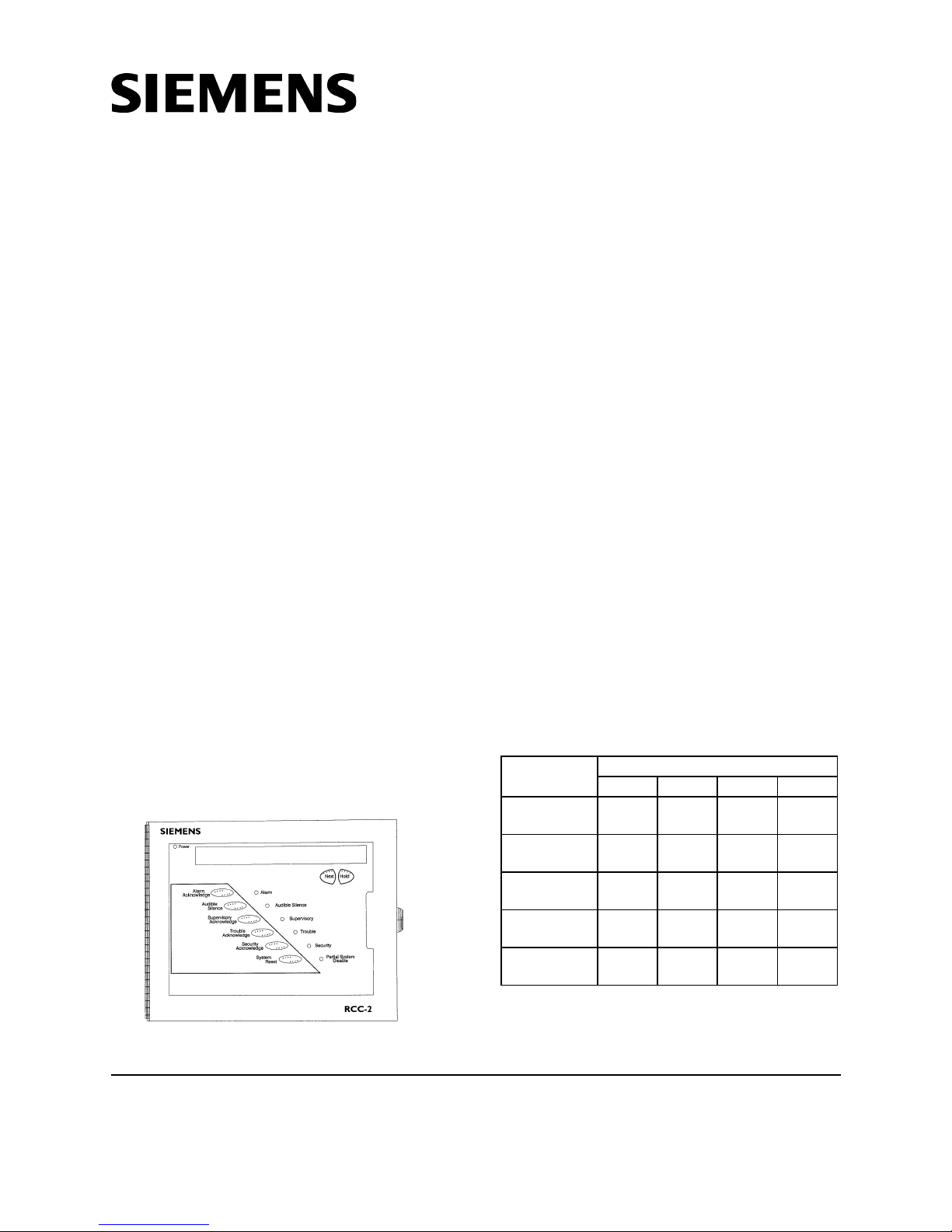
The Model RCC-2/R Remote Command Center
from Siemens Industry, Inc. (See Figure 1)
provides the option to remotely annunciate and
control MXL and MXL-IQ system status. The
RCC-2/R and RSE-1 provide for mounting and
control of the PIM-1 printer interface module.
The following modules come already installed in
an RCC-2/R:
• Keypad
• LCD Display
• ANN-1 Driver Board
• PS-5N7 Power Supply
The following modules come already installed in
an RSE-1:
• ANN-1 Driver Board
• PS-5N7 Power Supply
The RCC-2/R has a mounting location for an
optional PIM-1. The RSE-1 has the same
mounting and requires the PIM-1.
The RCC-2/R comes with a clear lens on a
secure door. This limits access to the control of
the system or the display. The door is secured
with a T-45 lock set.
OPERATION
The keypad on the RCC-2/R operates the same
as the MKB in the MXL enclosure. See Section 3
of the MXL Installation, Operation and Mainte-
nance Manual, P/N 315-092036, for the complete operating instructions for the control panel.
INSTALLATION
Always remove all power before installation, first the battery and then the AC.
Setting the Network Address
Before installing the RCC/RSE, set the network
address on S1-SW1 and S1-SW2 of the ANN-1
board. Refer to Table 1 for switch settings. (See
also Setting the Network Address in Section 2,
INSTALLATION of the MXL/MXLV Manual, P/N
315-092036.)
SWITCH SETTINGS ON THE ANN-1
SWITCH
S1-SW1
S1-SW2
S1-SW3
S1-SW4
S1-SW5
TABLE 1
ADDRESS SETTINGS FOR:
248 249 250 251
Open-
OFF
Open-
OFF
Closed-ONClosed-ONClosed-ONClosed-
Closed-ONClosed-ONClosed-ONClosed-
Closed-ONClosed-ONClosed-ONClosed-
Closed-ONOpen-
Open-
OFF
OFF
Closed-ONClosed-
Closed-
On
ON
ON
ON
ON
Figure 1
RCC-2/R Remote Command Center
Siemens Industry, Inc.
Building Technologies Division
Florham Park, NJ
P/N 315-099160-8
NOTE: Switches S1-SW3 and S1-SW4 are for
future use. Switch S1-SW5 is used to
select supervision.
Siemens Building Technologies, Ltd.
Fire Safety & Security Products
2 Kenview Boulevard
Brampton, Ontario
L6T 5E4 Canada

Setting Supervision
Use switch S1-SW5 on the ANN-1 to select or
deselect supervision. If your ANN-1 has a switch
with position 1 indicated on the left-hand side,
ignore the printing on the switch. SW1 on S1 is at
the extreme right-hand side of S1, regardless of
any other marking.
To set for supervision
S1-SW5 = Closed (ON)
To set for non-supervision
S1-SW5 = Open (OFF)
NOTE: When you select non-supervision for
an annunciator, there must also be
one and only one supervised annunciator at the same address.
Mounting
Before mounting the RCC/RSE, follow these
steps:
1. Remove the cover assembly from the
backbox.
2. Disconnect at P1 the cable from the PS-5N7.
3. Remove the PS-5N7 from the backbox (See
Figures 2 and 3).
4. Set the panel to one side.
2. Pull all field wiring into the backbox and
dress the wiring to the approximate location
to which it will go. Install field wiring to the
PS-5N7 (Refer to PS-5N7 Installation
Instructions,
3. If a PIM-1 is required, mount it to the set of
four standoffs to the right of the PS-5N7
(See Figures 2 and 3).
Connect P1 on the PIM-1 to P1 on the ANN-1,
using the 14 inch cable, P/N 555-192242.
Connect P2 on the PIM-1 to P1 on the PS-5N7,
using the 14 inch cable, P/N 555-192242
(Refer to PS-5N7 Installation Instructions,
P/N 315-092729, PIM-1 Installation
Instructions, P/N 315-091462 and Figure 6).
4. If a PIM-1 is not installed, reconnect P1 on
the ANN-1 to P1 on the PS-5N7.
5. Reattach the cover assembly to the
backbox.
6. Refer to the MXL/MXLV Manual, P/N 315-
092036, for additional information on the
operation of the keypad.
P/N 315-092729).
ELECTRICAL RATINGS
tnerruCeludoMCDV5evitcAAm0
Consider the following when mounting the
backbox:
• Mounting height for visual and manual
access to the keypad
• Weight and size of the enclosure
• Local mounting codes
To mount the RCC/RSE, follow these steps:
1. Fasten the RCC/RSE backbox securely to a
clean, dry, shock-free, and vibration-free
surface using the four mounting holes
provided. (Refer to Figure 4 for the
dimensions of the backbox and the location
of the mounting holes.) Position the RCC/
RSE backbox clear of obstructions so that
the door opens freely and the indicators and
controls are easily accessible.
eludoMCDV42evitcA
tnerruC
eludoMCDV42ybdnatS
tnerruC
WIRING
Refer to the following Installation Instructions as
needed:
MMB-2 P/N 315-095097
MMB-3 P/N 315-048860
PSR-1 P/N 315-090911
PS-35 P/N 315-085062
PLM-35 P/N 315-093495
PAD-3 P/N 315-099082
SMB-2 P/N 315-095931
MXL/MXLV Manual P/N 315-092036
Am51+Am56
desusi1-MIPfi
Am51+Am56
desusi1-MIPfi
2
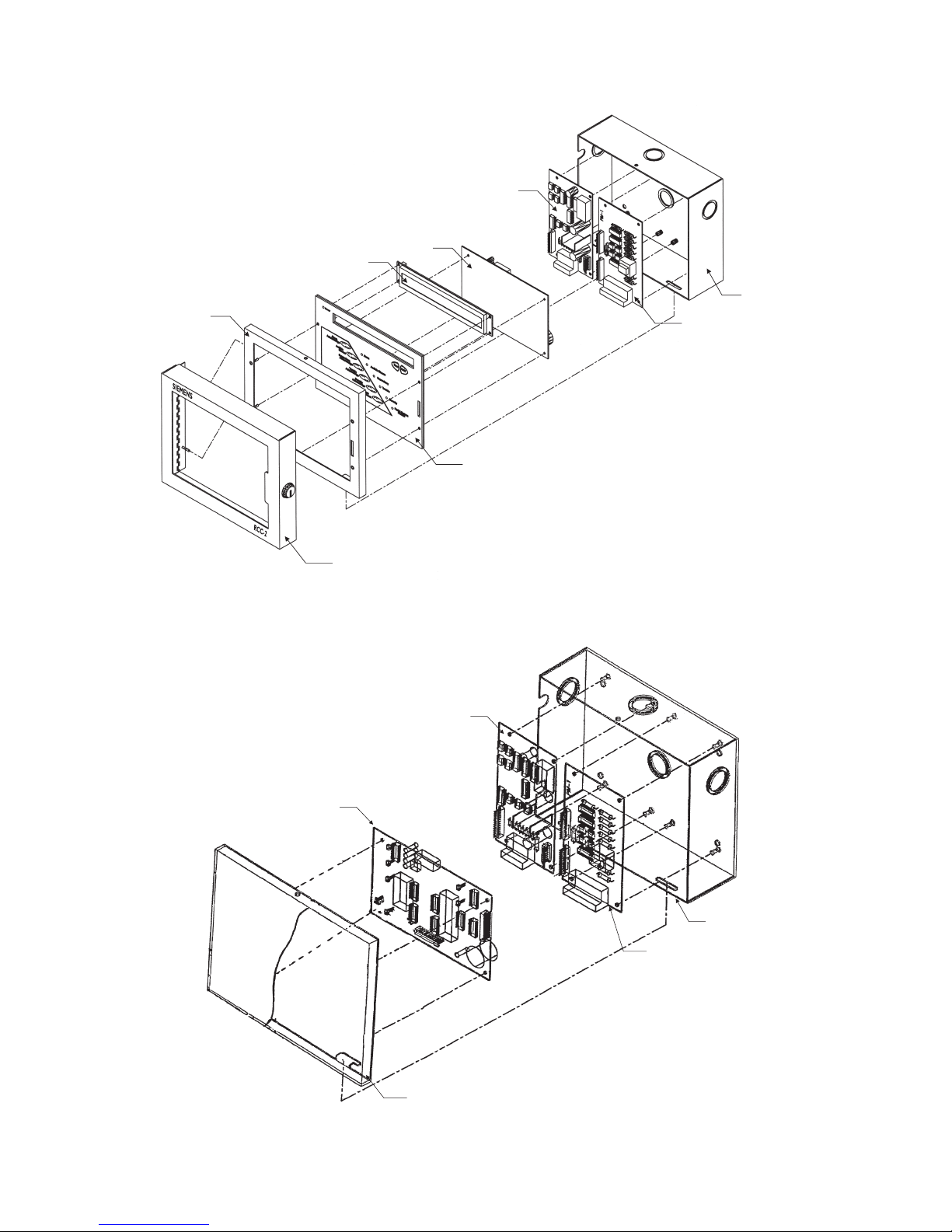
COVER
LCD DISPLAY
RCC-2/RSE-1
OUTER DOOR
PS-5N7
ANN-1
ANNUNCIATOR
PANEL
Figure 2
RCC-2/R Exploded View
RCC-2/RSE-1
PIM-1
BACKBOX
(OPTIONAL)
ANN-1
PS-5N7
RSE-1
BACKBOX
PIM-1
(REQUIRED)
RSE-1 OUTER DOOR
Figure 3
RSE-1 Exploded View
3
 Loading...