

Page 1
7
865.1
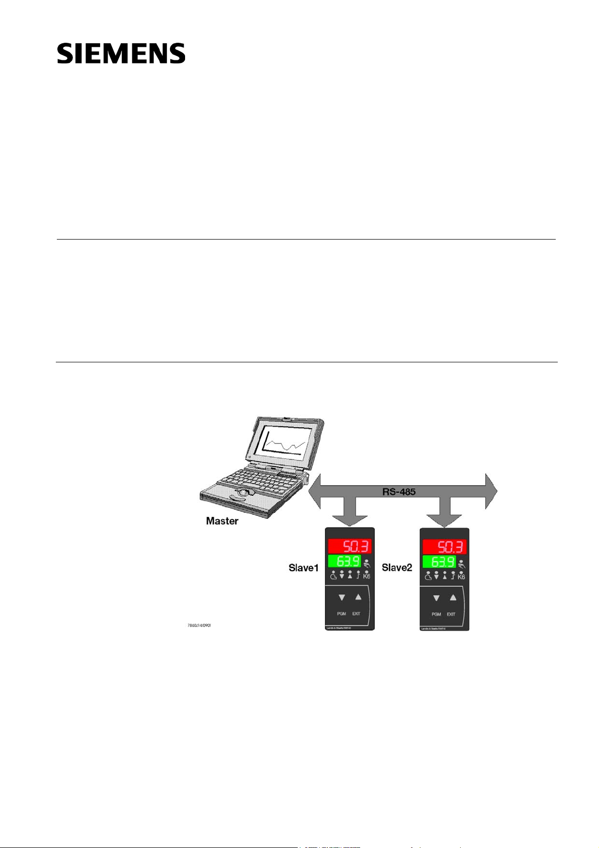
Master-slave principle
Interface RS-485
The RS-485 interface is used for integrating RWF40… controllers into data networks
via MOD bus protocol.
Application examples:
- Process visualization
- Plant control
- Reporting
Communication between a PC (master) and a device (slave) via MOD bus is based on
the master-slave principle in the form of data query / instruction – reply.
RWF40...
CC1A7865.1en
31.10.2002
A master computer controls the exchange of data and can address up to 99 controllers
via device addresses (slaves).
Siemens Building Technologies
HVAC Products
Page 2

Transmission mode (RTU)
The transmission mode used is the RTU (remote terminal unit) mode. Data are transmitted in binary format (hexadecimal) with 8 bits.
The LSB (least significant bit) is transmitted first.
ASCII mode is not supported.
Data format
Device address
The data format describes the structure of the transmitted byte.
Data word Parity bit Stop bit ½ bit Number of bits
8 bit Not 1 9
The slaves’ device addresses can be selected between 1 and 99.
Device address 0 is reserved.
A maximum of 31 slaves can be addressed via the RS-422 / RS-485 interface.
+
There are 2 choices of data exchange:
Query Data query / instructions delivered by the master to a slave via the re-
spective device address.
The addressed slave responds.
Broadcast Master instructions to all slaves via device address 0.
The addressed slaves do not respond.
A data query with device address 0 does not make sense.
A certain setpoint can be transmitted to all slaves, for example.
In that case, correct adoption of the value by the slaves should be
checked by subsequent setpoint readout.
2/14
Siemens Building Technologies CC1A7865.1en
HVAC Products 31.10.2002
Page 3

Communication sequence
Both the start and end of a data block are characterized by transmission pauses. The
maximum period of time that may elapse between 2 successive characters is 3 times
the period of time required for the transmission of one character.
The character transmission time (period of time required for the transmission of 1 character) is dependent on the Baud rate and the type of data format.
Using a data format of 8 data bits, no parity bit and 1 stop bit, the character transmission time is calculated as follows:
Character transmission time [ms] = 1000 * 9 bits / Baud rate
Process
Example
Data query by the master
Transmission time = n characters * 1000 * x bits / Baud rate
Identification of end of data query
3 characters * 1000 * x bits / Baud rate
Handling of data query by the slave (£ 250 ms)
Reply by the slave
Transmission time = n characters * 1000 * x bits / Baud rate
Identification of end of reply
3 characters * 1000 * x bits / Baud rate
Identification of the data query or end of the reply with a data format of 10 / 9 bits.
Waiting time = 3 characters * 1000 * x bits / Baud rate
Baud rate Data format [bits] Waiting time [ms]
9.600 9 2.813
19.200 9 1.406
3/14
Siemens Building Technologies CC1A7865.1en
HVAC Products 31.10.2002
Page 4

Data query sequence
Time sequence
The time sequence of a data query looks as follows:
Master
Slave
7865z12e/1102
Data query
Data query
Reply
t
t
0
1
t
t
0
2
t0 Identification of end = 3 characters
(time is dependent on the Baud rate)
t1 This time is dependent on internal handling.
The maximum handling time is 250 ms
t2 This is the time required by the device to switch from the transmitting mode back
to the receiving mode.
This time must be observed by the master before it makes a new data query. It
must always be maintained, even if the new data query is sent to some other
device.
t2 ³ 20 ms
Communication during the slave’s internal handling time
The master is not allowed to make any data queries during the slave’s internal handling
time.
Data queries made during that period of time will be ignored by the slave.
Communication during the slave’s response time
The master is not allowed to make any data queries during the slave’s response time.
Data queries made during that period of time cause all data currently on the bus to
become obsolete.
4/14
Siemens Building Technologies CC1A7865.1en
HVAC Products 31.10.2002
Page 5

Structure of the data blocks
All data blocks use the same structure:
Data structure
Fault handling
Error codes
Slave address Function code Data field Checksum CRC16
1 byte 1 byte x byte 2 bytes
Every data block contains 4 fields:
Slave address
Function code
Data field
Checksum
Device address of a certain slave
Function selection (reading or writing words)
Contains the following information:
- Word address
- Number of words
- Word value
Identification of transmission errors
3 different error codes are used:
1 Invalid function
2 Invalid parameter address
8 Write access to parameter rejected
Reply in the event
of fault
Example
Special cases
Slave address Function
Error code Checksum CRC16
XX OR 80 h
1 byte 1 byte 1 byte 2 bytes
The function code is OR linked with 0 x 80, that is, the MSB (most significant bit) will be
set to 1.
Data query:
01 02 00 70 00 04 CRC16
Reply:
01 82 01 CRC16
In the following cases, the slave does not reply:
- The checksum (CRC16) is wrong
- The instruction given by the master is incomplete or overdefined
- The number of words or bits to be read is zero
5/14
Siemens Building Technologies CC1A7865.1en
HVAC Products 31.10.2002
Page 6

Checksum (CRC16)
The checksum (CRC16) is used to detect transmission errors.
If the evaluation reveals an error, the relevant device will not respond.
Calculation
Example
CRC = 0xFFF
CRC = CRC XOR ByteOfMessage
For (1 to 8)
CRC = SHR (CRC)
if (flag to the right = 1)
then
CRC = CRC XOR
0xA001
while (not all ByteOfMessage edited)
The low byte of the checksum will be transmitted first.
else
+
Data query:
Reading 2 words from address 6 (CRC16 = 0x24A0)
0B 03 00 06 00 02 A0 24
CRC16
Reply:
(CRC16 = 0x6105)
0B 03 04 00 00 42 C8 61 05
Word 1 Word 2 CRC16
The following functions for the device will be available:
Function number Function
0x03 / 0x04 Reading n words (n £ 12)
0x06 Writing 1 word
0x10 Writing n words (n £ 2)
6/14
Siemens Building Technologies CC1A7865.1en
HVAC Products 31.10.2002
Page 7

Reading n words
This function is used to read n words from a certain address.
Data query
Reply
Example
Writing 1 word
Slave address Function 0x03
or 0x04
Address of the
first word
Number of
words
Checksum
CRC16
(max. 12)
1 byte 1 byte 2 bytes 2 bytes 2 bytes
Slave address Function 0x03
or 0x04
Number of
bytes read
Word value(s) Checksum
CRC16
1 byte 1 byte 1 byte x byte(s) 2 bytes
Reading the 2 setpoints of the controller
Word address = 0x0008 (setpoint SP1)
Data query:
0B 03 00 08 00 04 CRC16
Reply:
0B 03 08 0000 42C8 0000 4316 CRC16
Setpoint 1 (100) Setpoint 2 (150)
With the “Wordwriting” function, the data blocks for instruction and reply are identical.
Instruction
Reply
Example
Slave address Function 0x06 Word address Word value Checksum
CRC16
1 byte 1 byte 2 bytes 2 bytes 2 bytes
Slave address Function 0x06 Word address Word value Checksum
CRC16
1 byte 1 byte 2 bytes 2 bytes 2 bytes
Write limit value limit comparator 1 (AL1) (= 275)
Word address = 0x000C
Instruction: (write the first part of the value)
0B 06 00 0C 80 00 CRC16
Reply (like instruction):
0B 06 00 0C 80 00 CRC16
Instruction: (write the second part of the value)
0B 06 00 0D 43 89 CRC16
Reply (like instruction):
0B 06 00 0D 43 89 CRC16
7/14
Siemens Building Technologies CC1A7865.1en
HVAC Products 31.10.2002
Page 8

Writing n words
Instruction
Reply
Example
Data type “char“
Slave
address
Function
0x10
Address
of first
word
Number of
words
Number of
bytes
(max. 2)
Word
value(s)
Check-
sum
CRC16
1 byte 1 byte 2 bytes 2 bytes 1 byte x byte(s) 2 bytes
Slave address Function 0x10 Address of
first word
Number of
words
Checksum
CRC16
1 byte 1 byte 2 bytes 2 bytes 2 bytes
Write switch-on threshold (Hys1 = -10)
Word address = 0x0018
Instruction:
0B 10 00 18 00 02 04 00 00 C1 20 CRC16
Reply:
0B 10 00 18 00 02 CRC16
The high byte must be transmitted first.
Example: Configuration code C111: “9030“
MOD bus: 0B10 0024 00 02 04 0903
Data type “float“
The following explanations apply under the condition that the master works with the
IEEE-754 format. Before transmitting a value, the bytes must be exchanged in a way
that the order corresponds to the presentation for the MOD bus (see illustration below).
M-23 bit normalized mantissa
E-exponent (complement to base 2)
S-Sign-bit; 1 = negative, 0 = positive
MOD-Bus
Master
(IEEE 754)
MMMMMMMM
SEEEEEEE
MMMMMMMM
EMMMMMMM
SEEEEEEE
MMMMMMMM MMMMMMMM
EMMMMMMM
7865z13e/1102
Read
Write
Example:
Transmission of decimal value “550“:
MOD bus: 0x80, 0x00, 0x44, 0x09
Following is a description of all process values (variables) with their addresses, data
type and type of access.
Where:
R / O Read only access
R / W Read and write access
float Float value (4 bytes / 2 words)
word Integer (2 bytes / 1 word)
The process values are subdivided into logic areas.
8/14
Siemens Building Technologies CC1A7865.1en
HVAC Products 31.10.2002
Page 9

Address tables
Process data
Address Data
Access Parameter Value range Default
type
0x0000 float R / O Actual value E1
0x0002 float R / O Actual value E2
0x0004 float R / O Actual value E3
0x0006 float R / W Current setpoint
0x0008 float R / W SP1 First setpoint SPL...SPH 0
0x000A float R / W SP2 (=dSP) Second setpoint SPL...SPH 0
Parameter level
Address Data
Access Parameter Value range Default
type
0x000C float R / W AL Limit value limit comparator -1999...9999 0
0x000E float R / W Pb1 Proportional band 0.1...9999 10
0x0010 float R / W dt Derivative action time 0...9999 80
0x0012 float R / W rt Integral action time 0...9999 350
0x0014 float R / W db Dead band (neutral zone) 0.0...100.0 1
0x0016 float R / W tt Actuator running time 10...3000 15
0x0018 float R / W Hys1 Switch-on threshold 0...-199.9 -5
0x001A float R / W Hys2 Switch-off threshold, bottom 0...Hys3 3
0x001C float R / W Hys3 Switch-off threshold, top 0.0...999.9 5
0x001E float R / W q Reaction threshold 0.0...999.9 0
0x0020 float R / W H Heating curve slope 0.0...4.0 1.0
0x0022 float R / W P Parallel displacement
-90...90 0
room temperature
value
value
Configuration level
Address Data
Access Parameter Value range Default
type
0x0024 char [4] R / W C111 9030
0x0026 char [4] R / W C112 0010
0x0028 char [4] R / W C113 0110
0x002A char [4] R / W C000 0000
0x002C float R / W SCL Normalization start value: Input 1 -1999...9999 0
0x002E float R / W SCH Normalization end value: Input 1 -1999...9999 100
0x0030 float R / W SCL2 Normalization start value: Input 2 -1999...9999 0
0x0032 float R / W SCH2 Normalization end value: Input 2 -1999...9999 100
0x0034 float R / W SPL Start value setpoint limitation -1999...9999 0
0x0036 float R / W SPH End value setpoint limitation -1999...9999 100
0x0038 float R / W OFF1 Offset input 1 -1999...9999 0
0x003A float R / W OFF2 Offset input 2 -1999...9999 0
0x003C float R / W OFF3 Offset input 3 -1999...9999 0
0x003E float R / W HYST Hysteresis of limit comparator 0...9999 1
0x0040 float R / W df1 Filter time constant input 1 0.0...100.0 1.0
0x0042 float R / W dF3 Filter time constant input 3 0...1440 1278
0x0044 float R / W dtt Bus detection timer 0...7200 * 30
0x0046 float R / O oLLo Start value actual value limit -1999...9999 -1999
0x0048 float R / O oLHi End value actual value limit -1999...9999 9999
value
* Timer = 0 means switched off
This parameter can only be changed via the management system
9/14
Siemens Building Technologies CC1A7865.1en
HVAC Products 31.10.2002
Page 10

Device data
Address Data
Access Parameter Value range Default
type
0x0300 word [13] R / O Device data
0x0300 char SWVersion [11+1] Software version
0x0306 char VDNNr [13+1] VdN number
Remote operation
Address Data
Access Parameter Value range Default
type
0x0400 float R / O TEMP Actual value E3 (unfiltered)
0x0500 word R / W REM Activation remote operation 0...2 * 0
0x0501 word R / W ROFF Controller OFF in REMOTE
0...1 ** 0
SETPOINT
0x0502 float R / W RHYS1 Switch-on threshold REMOTE 0...-1999 HYS1
0x0504 float R / W RHYS2 Switch-off threshold bottom
0...RHYS3 HYS2
REMOTE
0x0506 float R / W RHYS3 Switch-off threshold top REMOTE 0...9999 HYS3
0x0508 float R / W SPR Setpoint REMOTE SPL...SPH SP1
0x050A word R / W RK1 Burner control remote operation 0...1 0
0x050B word R / W RK2 Relay K2 remote operation 0...1 0
0x050C word R / W RK3 Relay K3 remote operation 0...1 0
0x050D word R / W RK6 Relay LK remote operation 0...1 0
0x050E word R / W RSTEP Step control remote operation -100...100 0
0x050F float R / W RY Positioning output remote
0...100 0
operation
value
value
* 0 = local ** 1 = controller OFF
1 = remote setpoint
2 = fully remote
10/14
Siemens Building Technologies CC1A7865.1en
HVAC Products 31.10.2002
Page 11

Device state
Address Data type Access Parameter
0x0200 word R / O Outputs and states
B15 B14 B13 B12 B11 B10 B9 B8 B7 B6 B5 B4 B3 B2 B1 B0
B8 Hysteresis limitation B0 Output 1 off
(for remote operation) B1 Output 3 off
B9 Management system off B2 Output 2 off
(for remote operation) B3 Output 4 off
B10 Self-optimization active
B11 Second setpoint active
B12 Measured value range crossing input 1
B13 Measured value range crossing input 2
B14 Measured value range crossing input 3
B15 Reserved
0x0201 word R / O Binary signal and hardware identification
B15 B14 B13 B12 B11 B10 B9 B8 B7 B6 B5 B4 B3 B2 B1 B0
B15 Reserved B0 Operating mode 2-stage active
B14 Interface present B1 Manual operation active
B13 Analog output present B2 Binary input 1 closed
B3 Binary input 2 closed
B4 Thermostat function active
B5 First controller output active
B6 Second controller output active
B7 Limit comparator active
11/14
Siemens Building Technologies CC1A7865.1en
HVAC Products 31.10.2002
Page 12

Description of operating modes
General
RAM parameter for remote operation
Parameter «RemoteStatus» is used to switch between the operating modes «LOCAL»,
«REMOTE SETPOINT» and «FULLY REMOTE». The change is always accomplished
via the MOD bus.
In the event the master fails or communication is lost, the RWF40... will switch to operating mode «LOCAL». The time for detecting a failure is set via the interface.
Remote
parameter
REM Operating mode «LOCAL», «REMOTE SETPOINT» or
Default after
«Power-up»
= 0
«FULLY REMOTE»
SPR Setpoint remote = SP1
RHYS1 Switch-on threshold remote = Hys1
RHYS2 Lower switch-off threshold remote = Hys2
RHYS3 Upper switch-off treshold remote = Hys3
ROFF Controller ON (0) / OFF (1) in operating modes
= 0 ¹
)
«REMOTE SETPOINT» and «FULLY REMOTE»
RSTEP Number of control cycles (opening / closing) (FULLY
= 0 ²
)
REMOTE)
RK1 Release of burner (FULLY REMOTE) = 0 ³
RK2 Controlling element opens (FULLY REMOTE) = 0 ³
RK3 Controlling element closes (FULLY REMOTE) = 0 ³
RK6 Value of «K6» in operating modes «SETPOINT
)
)
)
= 0
REMOTE» and «FULLY REMOTE»
RY Degree of modulation for the analog output (FULLY
= 0
REMOTE) in %
¹)Controller active
)
²
No travel command (K2 + K3 = deenergized)
)
³
When the operating mode changes (e.g. LOCAL ® FULLY REMOTE), the relay
information and the degree of modulation will be predefined, depending on the
operating state of the plant.
Dtt Bus detection timer (value will also be maintained after a power failure)
The remote parameters are stored in RAM and will no longer be available after a power
failure.
After «Power-up», the default values will be used.
12/14
Siemens Building Technologies CC1A7865.1en
HVAC Products 31.10.2002
Page 13

Operating mode
«LOCAL»
The previous functions of the RWF40... are maintained (apart from memory usage).
The RWF40... can be parameterized and uploaded via the MOD bus, whereby the outputs cannot be changed. After «Power-up», the RWF40... will normally assume operating mode «LOCAL».
Operating mode
«REMOTE SETPOINT»
The RWF40... monitors cyclic bus communication via the «Dtt» parameter (bus detection timer). Operating mode «REMOTE SETPOINT» is active as long as the bus calls
within the predefined period of time. If the time limit is crossed, the RWF40... will switch
to operating mode «LOCAL» and continues to operate using the parameters of local
operation.
Like in operating mode «LOCAL», the control functions of the RWF40... are maintained.
With regard to setpoint and switching thresholds, only «RSP» and «RHYS1...RHYS3»
are active. The setpoints (SP1 and SP2), the external setpoint, the weathercompensated setpoint, the analog / binary setpoint shift and the associated changeover
functions are not available.
After the controller’s «Power-up», setpoint «SP1» and switching thresholds
«Hys1...Hys3» will be copied to RAM as remote parameters in a one-time operation.
These remote parameters can then only be changed via the management system.
The control algorithm can be deactivated by the management system via parameter
«ROFF=1». In that case, the RWF40... will switch the burner off and causes the controlling element to travel to the fully closed position. The controller terminates manual
operation (analog safety shutdown).
Self-optimization is not possible in this operating mode.
The management system controls contact «RK6» (relay «K6»).
Operating mode
«FULLY REMOTE»
The RWF40... monitors cyclic bus communication via the «Dtt» parameter (bus detection timer). Operating mode «FULLY REMOTE» is active as long as the bus calls within
the predefined period of time. If the time limit is crossed, the RWF40... will switch to
operating mode «LOCAL» and continues to operate using the parameters of local operation.
The management system switches the burner (RK1, relay «K1»), controls the actuator
(RK2 and RK3, relays «K2 / K3»), or defines the degree of modulation in the case of an
analog output, and controls contact «RK6» (relay «K6»).
Using parameter «ROFF=1», control of the burner and controlling element can be
switched off by the management system. In that case, the RWF40... deactivates the
burner and causes the controlling element to travel to the fully closed position.
Manual operation and self-optimization are not possible in this operating mode.
2-stage burner:
If, with a 2-stage burner, relay positions «RK2» and «RK3» are identical, the settings
are «K2 = deenergized» and «K3 = energized» (closing).
The analog output is set as follows, depending on the relay positions «RK2» and
«RK3»:
K2 = energized, K3 = deenergized ® analog output = 10 V or 20 mA
K2 = deenergized, K3 = energized ® analog output = 0 V or 0 / 4 mA
Setting the «RY» by the management system has no impact.
13/14
Siemens Building Technologies CC1A7865.1en
HVAC Products 31.10.2002
Page 14

Mudulating burner
Modulating controller:
The management system predefines the value (degree of modulation) for the analog
output via «RY».
Setting the «RK2» and «RK3» by the management system has no impact.
Both relays «K2» and «K3», are deenergized.
Floating step controller:
The management system controls the actuator («RK2» and «RK3», relays «K2» /
«K3»).
Setting the «RY» by the management system has no impact. In that case, the analog
output delivers 0 V or 0 / 4 mA.
The RWF40... always checks to ensure that «RK2» and «RK3» (opening / closing) are
not activated simultaneously. In such a case, the response is «K2 = K3 = deenergized».
If both relay contacts change their position during the controller’s sequence time, the
output is «K2 = K3 = deenergized». This time contact interval («K2 = K3 = off» for one
scanning time) is also permitted in 2-stage operation.
Control strategy for
floating output with
modulating burner
operation
Supervision of actual
value by setpointdependent switching
thresholds
The remote relay commands «RK2» and «RK3» (relays «K2» / «K3») control the
opening and closing travel of the controlling element. Using parameter «RSTEP», the
management system predefines the required number of control cycles.
Output «K2» (opening) is controlled by a travel command and a positive number.
Output «K3» (closing) is controlled by a travel command and a negative number.
The number gives the number of RWF40... scanning cycles (210 ms) with which the
output is controlled.
The travel command with number 0 deenergizes immediately «K2» and «K3».
If a new travel command is given before the control time has elapsed, the RWF40...
ascertains the direction of rotation requested by the command. If the direction of rotation does not change, the control time will immediately be replaced by the new value. If
the direction of rotation must be reversed, the controlled output will be dactivated and,
for the next scanning cycle, the appropriate control time is used (time contact interval).
If, simultaneously with the control strategy for the floating output, outputs «K2» and
«K3» (via «RK2» and «RK3») are directly set by the management system, the relay
information from the control strategy and output information «K2» and «K3» have a
logic «OR» connection. «RK2» and «RK3» (opening / closing) must never be energized
simultaneously. In such a case, the response is «K2 = K3 = denergized».
In operating mode «FULLY REMOTE», the management system ensures burner control. The RWF40... monitors the actual value to make certain the switching hystereses
will be observed.
If the actual value crosses the upper switch-off threshold, the management system will
be locked (status flag, «Management system locked» can be read via the interface).
The management system is released again when the actual value returns to a level
below the switch-on threshold.
If supervision of the actual value is not desired, the switching hystereses in the
RWF40... must be set to the respective maximum value.
In operating mode «REMOTE SETPOINT», the control algorithm ensures this kind of
supervision.
ã2002 Siemens Building Technologies
14/14
Siemens Building Technologies CC1A7865.1en
HVAC Products 31.10.2002
Subject to change!
 Loading...