

Page 1
725
2
Temperature controller
for ducted systems
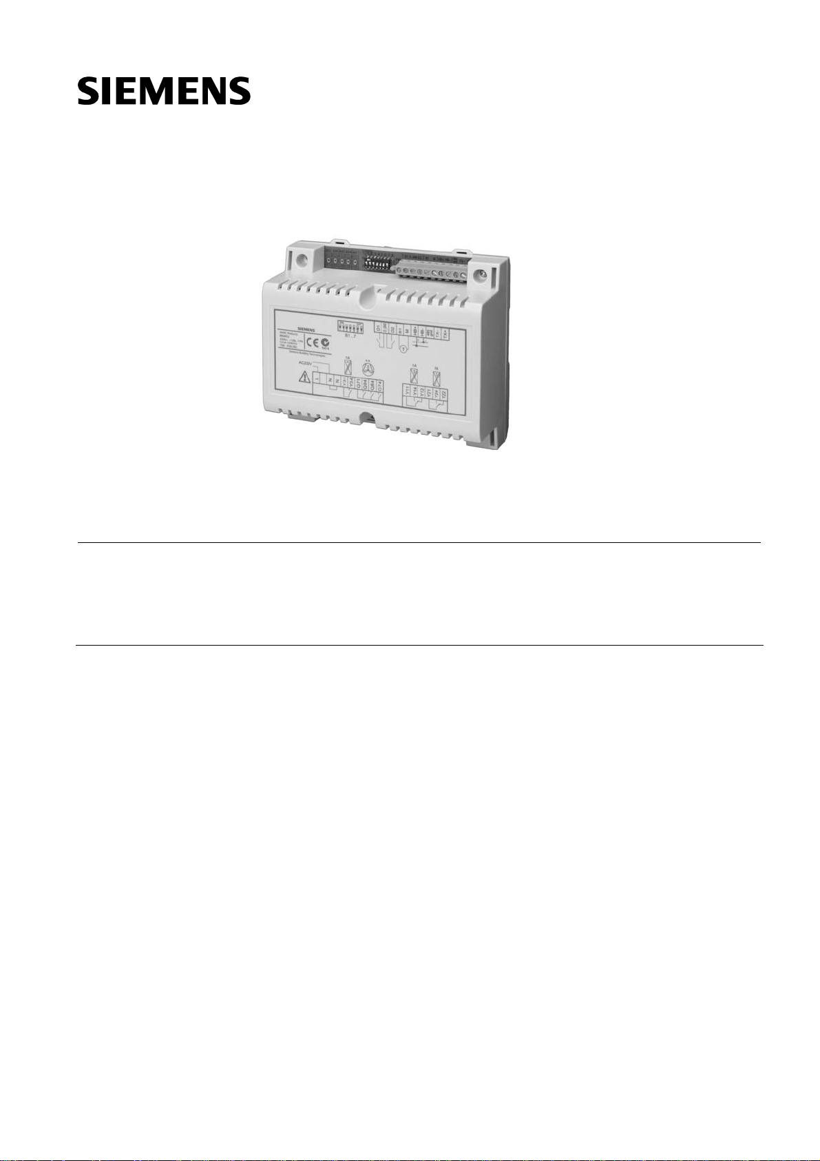
Multifunctional controller used for central control of ducted HVAC systems in
connection with a QAX850 master room unit.
Standard model without zoning functions.
Use
RRV851
Applications
Comfort control of ducted HVAC systems via fan, heating and cooling output:
• Apartments
• Single-family houses
• Autonomous light commercial applications
The RRV851 controller is designed for central ducted HVAC systems that require easy
operation by the building occupant. The MMI to be connected to the controller is the
QAX850 master room unit. Fan, heating and / or cooling outputs control the
temperature in the building. The RRV851 controller can be configured for various types
of HVAC equipment. These include:
• Heating only ducted systems
• Cooling only ducted systems
• DX cooling and heating (1-speed fan on heating)
• DX cooling and heating (3-speed fan)
• Air-to-air heat pumps
• Water-to-air heat pumps
• 4-pipe FCU
• 2-pipe FCU
• 1- or 3-speed fans
CE1N2725en
27.08.2007
Building Technologies
HVAC Products
Page 2
Functions
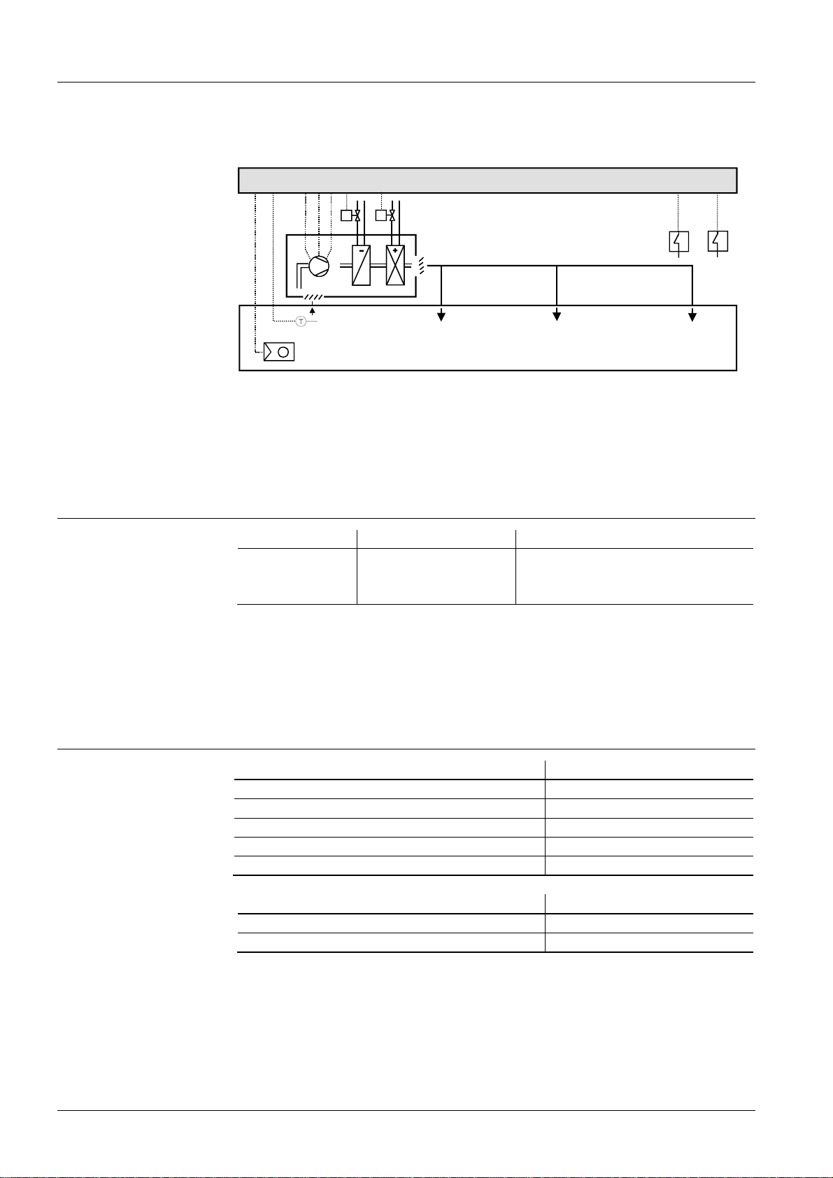
Application example:
4-pipe FCU system
The controller’s functionality is determined by the application selected with the DIP
switches, parameter settings and operating mode selection via the QAX850 master
room unit.
HB B1
Y1
Y2Y1Y3Q7Q8Q9
Y2
FCU
D1
D2
D2
N1
D1
Type summary
Note
SAF
B1
T
N2
B1 Optional remote temp. sensor N1 RRV851 controller
C1 Cooling coil N2 QAX850 master room unit
D1 Remote comfort mode input SAF Supply air fan
D2 Fault or emergency heat input Y1 Cooling control valve
FCU Fan coil unit Y2 Heating control valve
H1 Heating coil
C1
H1
Type reference Description Compatible with
RRV851
Temperature controller • QAX850 Master room unit
• QAA32 Room temperature sensor
• QAH11.1 Cable temperature sensor
The QAX850 is the master MMI for the RRV851 and must be ordered as a separate
item. Any additional remote temperature sensors must also be ordered separately.
Terminal covers are included in the RRV851 box.
2725A01
Not suitable for use with the Desigo RX range of wall-mounted units.
Product documentation
Document Document number
Data sheet N2725
Installation instructions G2725
Operating instructions, with QAX850 room unit B2725en01
Application manual A2725
Declaration of conformity T2725
Supporting
documentation
Document and unit type Document number
Data sheet QAX850 N2722
Mounting instructions QAX850 M2721
2/11
Siemens Temperature Controller RRV851 CE1N2725en
Building Technologies 27.08.2007
Page 3
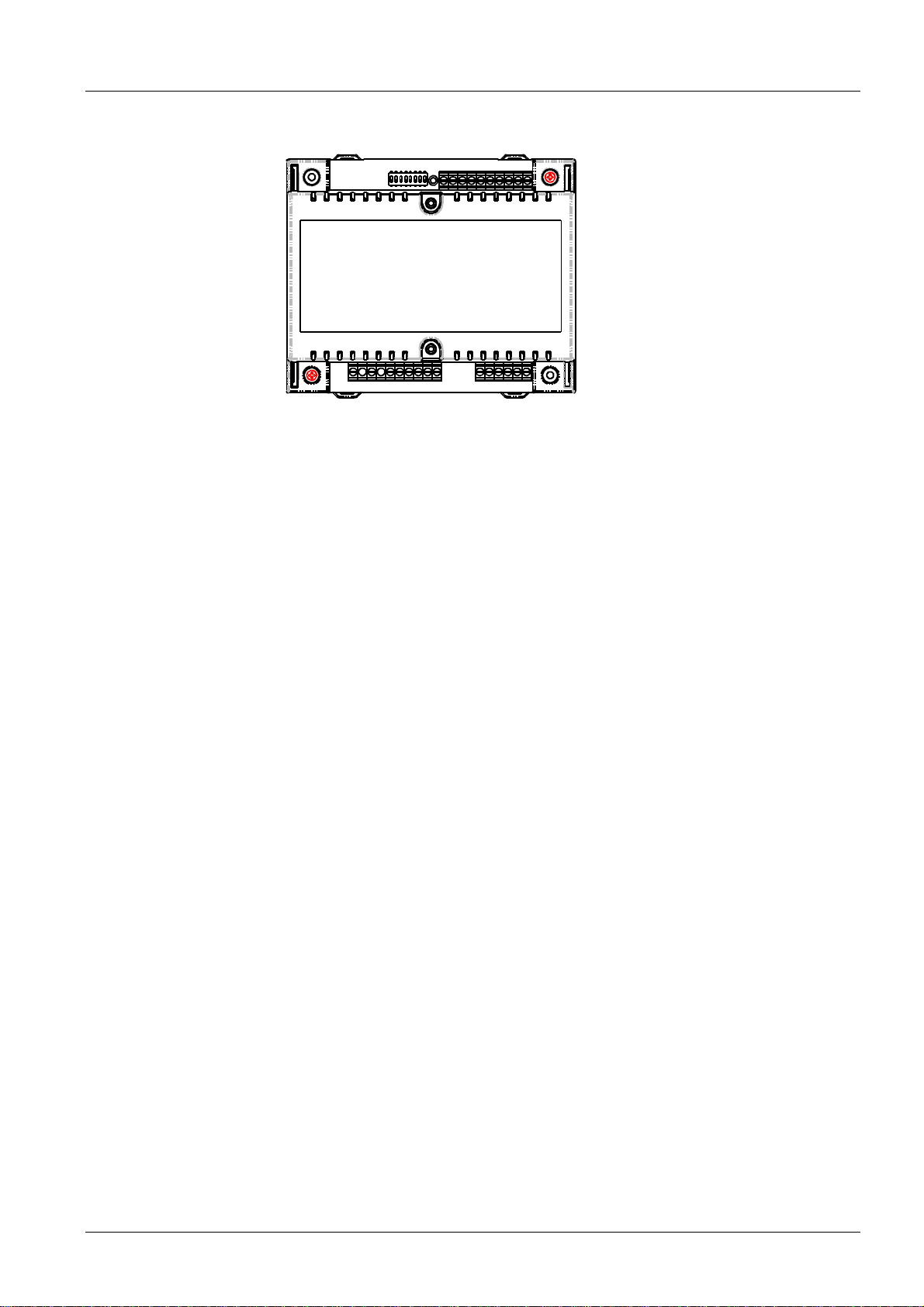
Mechanical design
The RRV851 is a temperature controller providing connection of power supply,
inputs/outputs and QAX850 master room unit.
2725Z01
The unit consists of the following components:
• Base for DIN rail or screwed surface-mounting
• Cable strain reliefs
• IP30 covers (when mounted directly to the wall or FCU without DIN rail)
• PCB and built-in transformer
• PCB cover
• Input / output terminals
• RS-485 terminals
• MMI bus terminals
• LED for power supply indication
• Configuration DIP switches
Connection terminals
Bus interface
(HB+ HB–)
RS-485
(TX+, TX–)
Digital inputs
(D1, D2)
Temperature sensor
input (B1, M)
Low-voltage power supply (DC 12 V) and communication transfer is supplied via two
wires to the QAX850 from terminals HB+ and HB–. The LED on the QAX850 will flash if
a communication error exists between RRV851 and QAX850 for longer than 5 seconds.
The RS-485 connections are only suitable for downloading manufacturer specific
parameter sets. This is for factory use only.
Two digital inputs are provided. A potential-free contact closed across the D1 and
D_GND terminals will override to Comfort mode only when the mode selector is set to
Auto Timer mode. D2 can be configured for an emergency heating enable signal or an
external fault lockout signal. Either of these functions can be selected via the
configuration DIP switches.
When emergency heating is selected, a potential-free contact closed across the D2 and
D_GND terminals will disable the primary heating output and enable the emergency
heating output. The emergency heating output will only be activated when there is
demand for heating. Not available on applications A2, A3, A4, and A5.
When external fault (default) is selected, a potential-free contact closed across the D2
and D_GND terminals will deactivate all outputs and the standby icon on the QAX850
LCD will flash to indicate the fault. The fault will disappear after the contact is opened.
An NTC temperature sensor can be connected to the B1 and M terminals for the
following functions:
3/11
Siemens Temperature Controller RRV851 CE1N2725en
Building Technologies 27.08.2007
Page 4
Fan speed outputs
Heat/cool outputs
• Remote room temperature sensing: The QAX850 can be used as a master control
unit without using the built-in temperature sensor. A separate room sensor (QAA32)
can be mounted in a location more convenient for accurate temperature acquisition
• Return air temperature sensing: A temperature sensor (QAH11.1) can be mounted in
the return air path of the FCU if accurate temperature acquisition in the room is not
possible
• 2-pipe application heating/cooling changeover: For application A8 (2-pipe FCU) a
temperature sensor (QAH11.1/ARG86.3) is clamped to the water pipe in order to
activate heating/cooling mode changeover
The RRV851 controller can be configured for a 1- or 3-speed fan. Voltage-free (SPST)
relay outputs Q74, Q84 and Q94 can switch loads up to AC 250 V, 6 (4) A. Power is
supplied via terminal Q71. The low-speed terminal is used when a 1-speed fan is
configured. On fan startup, high-speed will be activated first for approximately
3 seconds and then resume the selected speed. In Auto Fan mode, the fan speeds will
be activated automatically depending on demand.
For further details on auto fan speed control, refer to the Application Manual.
• Output Y1: Cooling or compressor output
• Output Y2: Heating or reversing valve output
• Output Y3: Auxiliary output that can be configured for auxiliary heating, emergency
nd
heating, 2
step cooling or dual compressor
Output control is 2-position. 3-position modulating can be selected via parameter P17
for applications A1, A2 and A8 only.
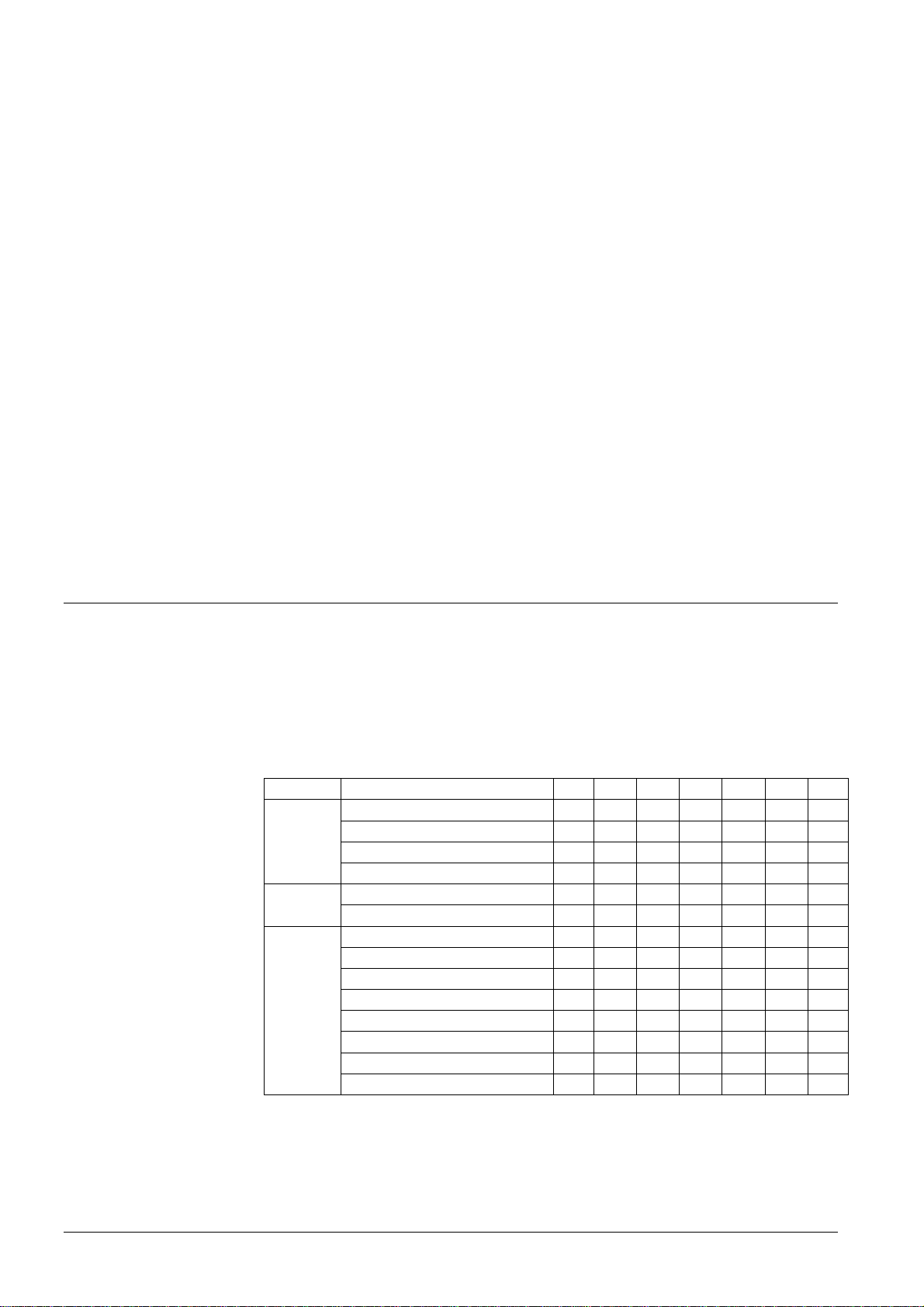
Configuration
DIP switches
DIP switch settings
Initial application setup of the RRV851 controller to match the connected HVAC
equipment is made by the selection of DIP switch positions. DIP switches are located
on the top of the controller. An adhesive label is included in the RRV851 packaging box
for the final recording of the DIP switch positions. This can be placed on the DIP switch
block to avoid unauthorized changes. Further parameter settings can be made via the
QAX850 if required.
Function Selections 1 2 3 4 5 6 7
Y3
Auxiliary
output
Auxiliary heating 20 min delay
Auxiliary heating 10 min delay on off - - - - Emergency heating via D2 off on - - - - -
nd
stage cool or compressor on on - - - - -
2
off off
- - - - -
Single speed - - off - - - - Fan
speed
Application
Three speed - -
A1 – Heating only
A2 – Cooling only
A3 – Cool./(heat. 3 speed fan)
A4 – Cool./(heat. 1 speed fan)
A5 – Heat pump (comp + RV)
A6 – Heat pump (heat/cool)
A7 – 4-pipe FCU
A8 – 2-pipe FCU
- - -
- - - on off off off
- - - off on off off
- - - on on off off
- - - off off on off
- - - on off on off
- - - off on on off
- - - on on on off
on
- - - -
off off off off
Default (as delivered) positions are in bold text.
4/11
Siemens Temperature Controller RRV851 CE1N2725en
Building Technologies 27.08.2007
Page 5

Commissioning notes
Response on startup
User operation
Sensor calibration
Commissioning
Setup parameters
When powering up, the QAX850 will display all LCD icons for approximately 3 seconds,
and then the software version number for another 3 seconds. It will then revert to the
normal display. The time segments will be blinking if the time needs to be set. Set the
time of day as per Operating Instructions. There will be a delay before operation
commences due to polling of all values.
The user should not have access to the DIP switches or parameter settings. User
operation is via the QAX850 master room unit. For user operation details, refer to the
Operating Instructions included in the packaging box (document B2725en.01).
Generally, there is no need to recalibrate the sensor. However, the room temperature
displayed on the QAX850 LCD can be recalibrated if there is any discrepancy from the
actual temperature measured with a certified thermometer. The calibration function can
be accessed by pressing simultaneously the
and buttons for 5 seconds. The
displayed value can then be adjusted via the same buttons in increments of 0.1 K. The
range is ±3 K.
The RRV851 controller is operational after the DIP switch settings have been made and
power is connected. Default parameter settings are based on the application selected
and may be modified if required. Refer to the list below. Parameters cannot be
accessed if the system is in Off mode. Refer to the Installation Instructions for setup
details and the Application Manual for default parameter values.
No. Parameter Range
P00 Temperature scale °C / F°
P01 Frost protection limit in Off mode Off / 5…8 °C
P02 Overtemperature limit in Off mode Off / 30…35 °C
P03 Min. off time delay 0…600 s
P04 Min. on time delay 0…600 s
P05 Dead band between cooling and heating off points 0.5…6 K
P06 RV on in heating or cooling mode Heating/Cooling
P07 Fan run on after heating output turns off 0…300 s
P08 Fan run on after cooling output turns off 0…300 s
P09 FCU flush pipe time 120…600 s
P11 Water temperature heating mode changeover 22…32 °C
P12 Water temperature cooling mode changeover 10…21 °C
P13 Fan auto speed high range H: 80…100 %
P14 Fan auto speed medium range M: 30…75 %
P15 Fan auto speed low range L: 1…15 %
P17 2- or 3-position control selection 2-pos / 3-pos
P18 P-band in heating mode / switching differential 0.5…10 K
P19 P-band in cooling mode / switching differential 0.5…10 K
P20 Integration time 0…60.0 min in
0.5 min steps
P21 3-position valve actuator running time 50…300 s
P23 Ventilation in dead zone Off, H/C, C only
5/11
Siemens Temperature Controller RRV851 CE1N2725en
Building Technologies 27.08.2007
Page 6

Mounting and installation notes
The RRV851 controller can be mounted in any orientation using the following fixing
options:
DIN rail mounting
The housing base is designed for snapmounting on DIN rails conforming to
EN 50022-35 × 7.5 (can be released
with a screwdriver).
When mounting, note the following:
• The controller should not be freely accessible after mounting
• Ensure adequate air circulation to dissipate heat generated during operation
• Easy access is required for service personnel
• Local installation regulations must be observed
Surface mounting
There are 2 drill holes for screw-mounting
(refer to “Dimensions”).
Screws: Max. diameter 3.5 mm, min. length
38 mm.
STOP
Note!
Terminal covers
The Mounting Instructions are included in the RRV851 controller packaging.
When not mounting within a panel, cable strain
2725Z02
reliefs must be used for all wiring to (AC 230 V)
terminals. The conductors must be secured with
cable ties (see diagram).
Cable strain reliefs should be used for all wiring
to avoid disconnection.
Terminal covers are provided in the RRV851 packaging box. The covers include
screws for fixing to the controller and knockout holes for cable entry. Covers should
only be used where suitable access is restricted to authorized personnel and there is
protection from ambient conditions. The covers will provide IP30 protection when
surface-mounted on the wall or FCU.
Removing the terminal covers
6/11
Siemens Temperature Controller RRV851 CE1N2725en
Building Technologies 27.08.2007
Page 7

Technical data
Power supply (L, N)
Rated voltage AC 230 V, +10 %, –15 %
Requirement for transformers for switch mode
power supplies
Functional data
Analogy input (B1, M)
Digital input (D1, D2)
Frequency 50 / 60 Hz
Power consumption (excl. external modules) 12 VA
Supply line fusing max. 10 A
Reserve of clock max. 20 min
Passive sensor NTC resistor, 3 kΩ at 25 °C
Measuring range 0…49 °C
Contact sensing
Voltage
Current
Requirements for status and impulse contacts
Signal coupling
Type of contact
Insulating strength against main potential
Switching outputs
External supply line fusing
Non-renewable fuse (slow)
Automatic line cutout
Release characteristic
Relay contacts (Y1x, Y2x, Y3x)
Relay output
Switching voltage
AC current
At 250 V
At 19 V
Switch-on current
Contact life
Boiler (Q1x) Relay contacts (Q7x)
Relay output
Switching voltage
AC current
At 250 V
At 19 V
Switch-on current
Contact life
Insulating strength
Between relay contacts and system electronics
(reinforced insulation)
Between neighboring relay contacts
(operational insulation)
Y1x⇔Y2x⇔Y3x⇔Q7x⇔Q8x⇔Q9x
Interfaces (S+, SG)
HCC bus proprietary protocol
Bus power supply voltage DC 12 V, +10, –15% (supply to room
EN 61 558-2-6
max. DC 5 V
typically 8 mA
Potential-free
Maintained or impulse contacts
AC 3750 V to EN 60 730
max. 10 A
max. 13 A
B, C, D to EN 60 898
potential-free
max AC 250 V
min. AC 19 V
max. 3 A res., 1 A ind. (cos φ= 0.6)
min. 5 mA
min. 20 mA
max. 5 A (1 s)
5
1 × 10
cycles
potential-free
max. AC 250 V
min. AC 19 V
max. 6 A res., 4 A ind. (cos φ= 0.6)
min. 5 mA
min. 20 ma
max. 10 A (1 s)
5
1 × 10
cycles
AC 3750 V, to EN 60 730-1
AC 1250 V, to EN 60 730-1
unit QAX850)
7/11
Siemens Temperature Controller RRV851 CE1N2725en
Building Technologies 27.08.2007
Page 8

Permissible cable lengths
Electrical connections
(all terminals)
Degrees of protection
Environmental conditions
Classification to EN 60 730
Materials and colors
Norms and standards
Weight
Baud rate 9.6 kbit/s
For bus communication
A ≥0.5 mm²
A ≥1 mm²
max. 60 m
max. 100 m
Type of cable 2-wire standard installation cable
(unshielded)
Note:
Twisted pair (unshielded) is recommended for enhanced
immunity to external electromagnetic interference, e.g. in the
vicinity of radio transmitters or variable speed drives
Connection terminals
For wires
screw terminals
0.6 mm dia. … 2.5 mm
2
Degree of protection of housing to IEC 60 529 IP 20 without terminal covers
IP 30 with terminal covers
Safety class to EN 60 730 device suited for use with equipment
of safety class II
Operation to
Climate conditions
Temperature (housing and electronics)
Humidity
Mechanical conditions
Transport to
Climate conditions
Temperature
Humidity
Mechanical condition
IEC 721-3-3
class 3K5
0…50 °C
5…95 % r. h. (non-condensing)
class 3M2
IEC 721-3-2
class 2K3
–25…+70 °C
<95 % r. h.
class 2M2
Mode of operation, automatic controls type 1B
Degree of contamination, controls Environment 2
Rated surge voltage
4000 V
Software class A
Controller housing Polycarbonate, RAL 7035 (lightgrey)
Packaging corrugated cardboard
Product safety
Automatic electrical controls for household and
similar use
Special requirements for temperature sensing
controls
Electromagnetic compatibility
Immunity domestic section, light industry
Emissions domestic section, light industry
-conformity
EMC directive
Low-voltage directive
N474
conformity to
Australian EMC framework
Radio interference emission Standard
EN 60 730-1
EN 60 730-2-9
EN 61 000-6-1
EN 61 000-6-3
89/336/EEC
73/23/EEC
Radio Communication Act 1992
AS/NZS 4251.1
Excluding packaging approx. 0.735 kg
8/11
Siemens Temperature Controller RRV851 CE1N2725en
Building Technologies 27.08.2007
Page 9

Connection terminals
Connection diagrams
Typical connection
B1 Signal input (external sensor NTC)
M Signal ground
D1, D2 Digital inputs
D_GND Digital ground
HB+ HB– Communication bus
L, N AC 230 V supply
Q… Digital outputs, AC 24…230 V, 6(4) A
Y… Digital outputs, AC 24…230 V, 3(1) A
D1
B1
1
B
M
D2
D
N
G
1
2
_
D
D
D
RS485
-
+
X
X
T
T
N1 N2
5
d
8
n
4
g
4
4
N
Q
1
7
L
4
1
7
8
9
Q
Q
Q
4
3
3
Y
Y
4
2
1
1
1
1
Y
Y
Y
4
2
1
2
2
2
Y
Y
Y
-
+
B
B
H
H
L
N
AC 230V
2
1
3
F1
1
Y1
Y3
Y2
F2
B1 External temperature sensor (optional) or pipe changeover sensor (application A8)
CR1 Compressor relay stage 1
CR2 Compressor relay stage 2
D1 Remote activation of Comfort mode
D2 Fault or emergency heating
F1 3-speed fan
F1 External supply line fusing, max. 10 A
F2 1-speed fan
N1 RRV851 controller
N2 QAX850 master room unit
RV Reversing valve
Y1 Cooling output
Y2 Heating output
Y3 Auxiliary heating, emergency heating or 2
Y4 Valve actuator, AC 24…230 V
nd
stage cooling
-
+
B
B
H
H
9/11
Siemens Temperature Controller RRV851 CE1N2725en
Building Technologies 27.08.2007
Page 10

Output connections
N1
N1
Output connections
STOP
Note
4
1
2
1
1
1
Y
Y
Y
1
2
Y
Y
4
1
2
2
2
2
Y
Y
Y
AC 24
/230V
4
1
2
1
1
1
Y
Y
Y
1
2
Y
Y
Y4
Y4
4
1
2
2
2
2
Y
Y
Y
AC 24
/230V
2-pipe FCU, 2-position control
(application A8)
Optional 3-position control (applications
A1, A2 and A8)
N1
4
1
4
1
3
3
Y
Y
CR2
2
1
1
1
Y
Y
Y
CR1
4
1
2
2
2
2
Y
Y
Y
AC 24
RV
/230V
Heat pumps (application A5)
(For single compressor heat pumps, CR2 is
not connected)
Note: Contact your local Siemens representative for application-specific wiring
diagrams and information.
• External supply line fusing must be used.
• All input and bus terminals are not protected against connection to AC 230 V.
• Observe the technical data for fan relay outputs: Max. AC 250 V, 6(4) A.
• All output cables used must satisfy insulation requirements with regard to
mains potential.
• AC 24 V outputs must be segregated from AC 250 V outputs.
• Care should be taken when cables pass through sharp metal openings,
conduits or ducts.
• Double insulation on output cables is recommended.
• Local installation regulations must be observed.
Product liability
The products may only be used in building services plant and applications as described
above. When using the products, all requirements specified under ”Technical data”
must be observed.
10/11
Siemens Temperature Controller RRV851 CE1N2725en
Building Technologies 27.08.2007
Page 11

Dimensions
Without terminal covers
With terminal covers
Dimensions in mm
©2005-2007 Siemens Switzerland Ltd
Subject to alteration
Siemens Temperature Controller RRV851 CE1N2725en
Building Technologies 27.08.2007
11/11
 Loading...