

Page 1
1
2
3
4
5
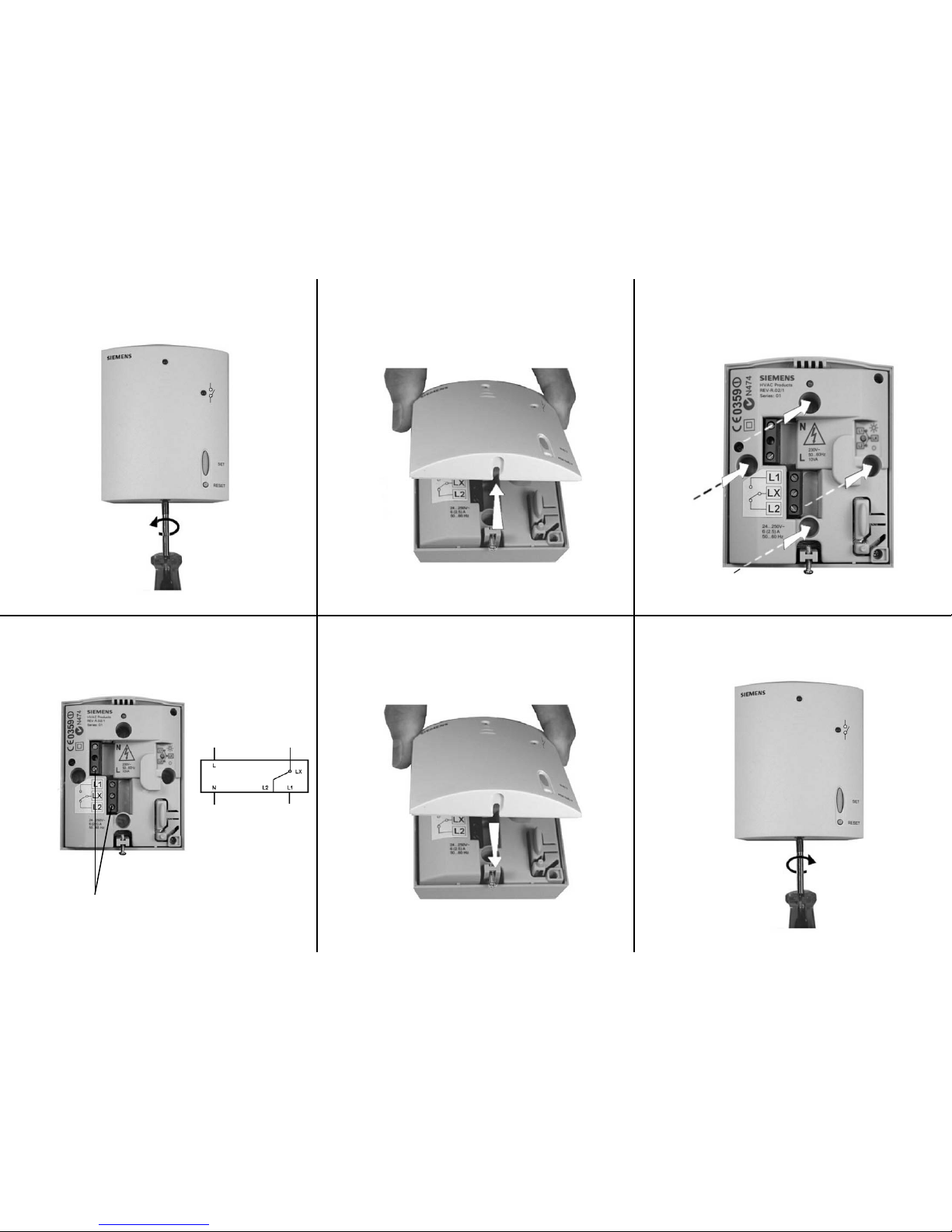
Installation Instructions for the Siemens RF
receiver
s
Technical Helpline: 0870 850 0184
6
Wiring Diagram
Legend
LX = Common
L1 = Live feed to
item to be
controlled
L2 = Changeover
contact
L = Live
N = Neutral
Terminals
Item to be controlled
Page 2
1
2 3
4 5 6
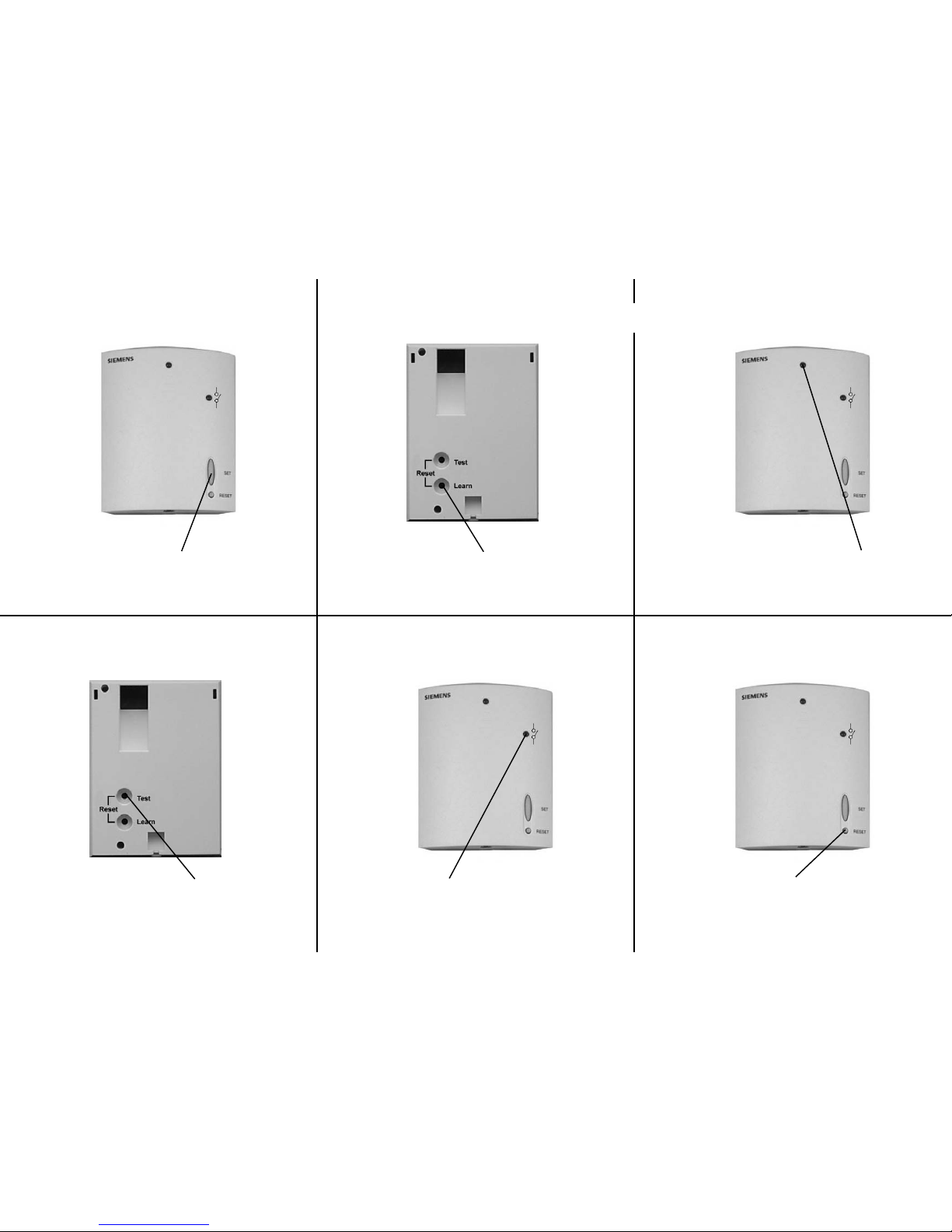
Press and release LEARN button
on the back of the transmitter
To test transmission press TEST on the
transmitter
This will switch relay on in receiver irrespective
of temperature
RF TEST appears in transmitter display. To switch
test off press TEST again
Configuration Instructions for the Siemens RF
units
Press and release SET button, this
puts the receiver into learn mode
Good signal is indicated by the LED
flashing green, then solid
No signal is indicated by the LED
flashing red, then solid
Orange LED indicates relay is on Pressing the RESET button for about 4
seconds will erase all ID codes in the
receiver. The set up procedure has to
be repeated to regain communication
Note: The transmitter and receiver are supplied in a single box already configured. This
procedure only needs to be followed in case of communication issues
PKGPT01027A
Page 3
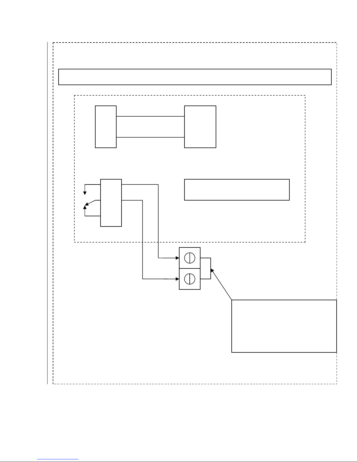
SIEMENS
RDH/RDJ-RF/RECEIVER. RCR10/433
N
L
L1
LX
L2
AC
230
VOLT
NOTE, LX, L1 & L2 ARE
‘VOLTS FREE’ CONTACTS.
BOILER
TERMINAL BLOCK
REMOVE LINK - Marked
(TO EXTERNALCONTROLS)
&
CONNECT AS SHOWN
Page 4
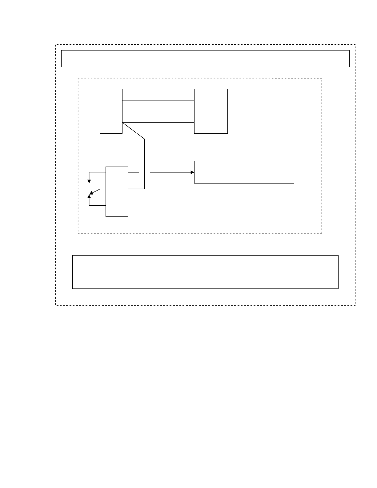
SIEMENS
RDH/RDJ- RF/RECEIVER. RCR10/433
N
L
WIRE
LINK
L - LX
L1
LX
L2
NOTE, LX, L1 & L2 ARE VOLTS FREE CONTACTS.
TO SWITCH, 230VOLT MAINS LIVE ON L1, PUT LINK BETWEEN L & LX
AC
230
VOLT
230 VOLT, SWITCH LIVE
TO BOILER OR VALVE
Page 5
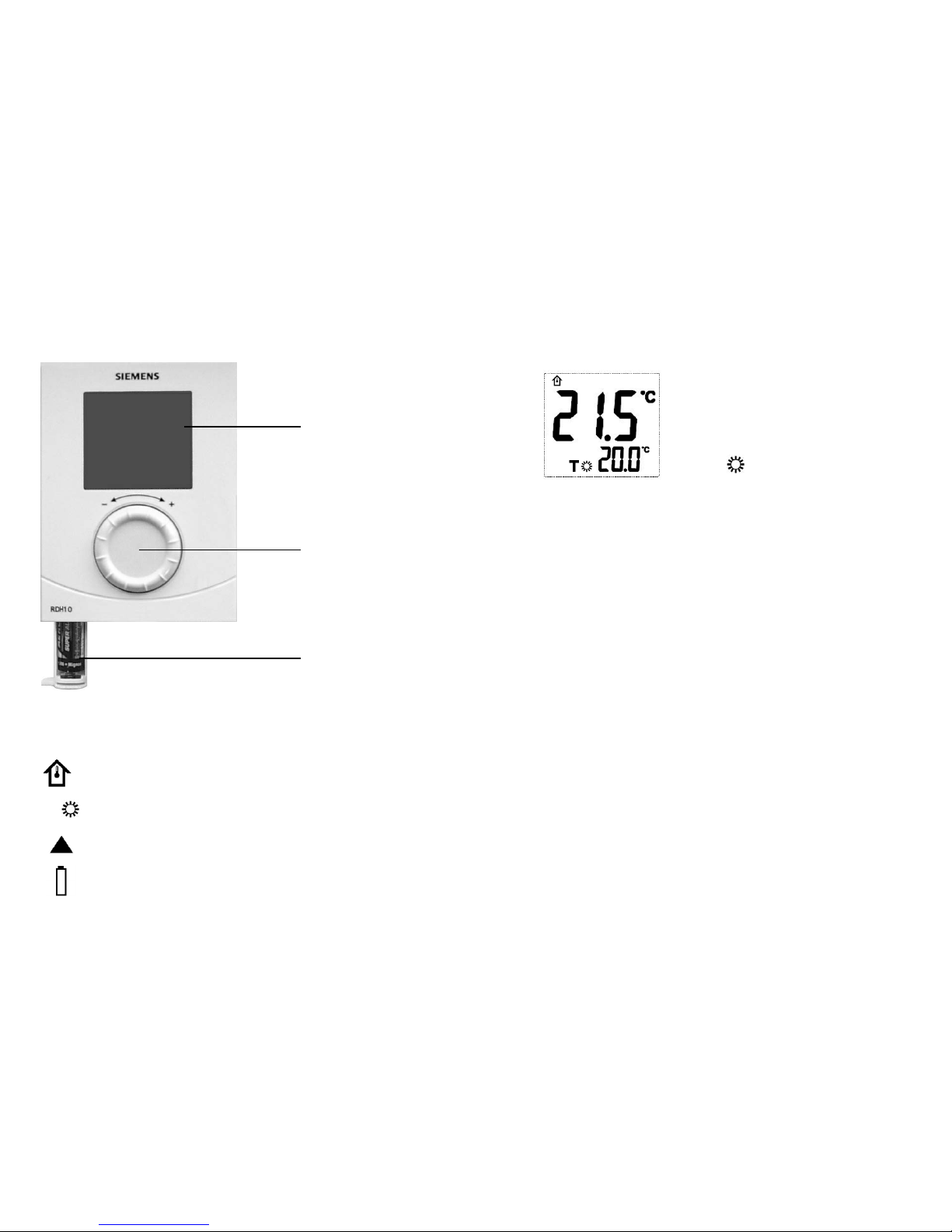
T
LCD Display
Guide to symbols
On LCD Display
Actual room temperature in °C
The selected temperature
Indicates there is a call for heat
Indication of low battery life, this signifies batteries must be replaced
How to use your Siemens RDH10/RDH10RF
Digital Room Thermostat
This leaflet gives you easy to follow instructions on how to use your RDH10 digital room thermostat.
Technical Helpline: 0870 850 0184
s
Rotary Dial
How do I set the required temperature?
Turn the rotary dial to the left to decrease the
required temperature, or to the right to increase the
required temperature.
The required temperature is displayed next to the
following symbol
T
Batteries Compartment
The RESET button on the back of the controller can be pressed to return the controller
to the factory settings
PKGPT01020A
Page 6

CE1N3070en
20.11.2007
Building Technologies
3
070
Wireless room
temperature controller
with large LCD
RDH10RF/SET
Non-programmable, for heating or cooling systems
• Large LCD
• Battery-powered: 2 x alkaline type AA batteries, 1.5 V
• RCR10/433 receiver
Use
The RDH10RF is used to control the room temperature in heating or cooling systems.
Typical applications:
• Homes
• Residential buildings
• Schools
• Offices
The controller is used together with the following equipment:
• Thermal valves or zone valves
• Combi boilers
• Gas or oil burners
• Fans
• Pumps
Page 7

2/10
Siemens Room temperature controllers CE1N3070en
Building Technologies 20.11.2007
Functions
The controller acquires the room temperature with its integrated sensor.
Q14
T[°C]
ON
OFF
W
SD
3031D01
T Room temperature
SD Switching differential
W Room temperature setpoint
L1 Output signal for heating
Y2
T[°C]
ON
OFF
SD
3011D02
T Room temperature
SD Switching differential
W Room temperature setpoint
L1 Output signal for cooling
The RDH10RF provides room temperature control only.
The digital display shows the actual room temperature and the comfort temperature
setpoint. When the heating output is active, the triangle symbol appears.
When taking out the batteries, the setpoints and the information required for operating
mode changeover are retained for maximum 2 minutes.
Ordering
When ordering, please give name and product number: Room temperature controller
RDH10RF/SET.
Valves and actuators are to be ordered as separate items.
Equipment combinations
Type of unit Product number Data sheet
Electromotoric actuator
SFA21...
4863
Electrothermal actuator (for radiator valves)
STA21...
4877
Electrothermal actuator (for small valves 2.5 mm)
STP21...
4878
2- or 3-port zone valve
MXI/MVI421…
4867
Electromotoric actuator for zone valves V..146..
SUA21
4830
Electric actuator
SUA11/22
4832
Air damper actuator
GDB…
4624
Air damper actuator
GSD/GQD…
4606
Air damper actuator
GXD…
4622
.
.
.
Function diagram
Temperature sensor
Display
Backup
L1
L1
Page 8

3/10
Siemens Room temperature controllers CE1N3070en
Building Technologies 20.11.2007
Mechanical design
The controller consists of 4 parts:
• Plastic housing with digital display accommodating the electronics, operating ele-
ments and built-in room temperature sensor
• Baseplate (mounting base)
• Removable battery compartment
• Fold-out stand
The housing engages in the baseplate and snaps on. The baseplate carries the screw
terminals. There is a reset button on the rear of the unit.
1
Display of the room temperature in °C
2
Indicates a request for heat
3 Temperature setting knob
4 Battery compartment
5
Comfort temperature setpoint
6
RF
TEST Indicates RF signal test
7
Indicates low battery power; replace batteries
Key
Page 9

4/10
Siemens Room temperature controllers CE1N3070en
Building Technologies 20.11.2007
Mechanical design
The RCR10/433 receiver is located in a plastic housing with LEDs and buttons.
1 LED signal indicator
2 LED relay indicator
3 SET button
4 RESET button
5 Test button
6 Learn button
Notes
Mount the room temperature controller in a location where the air temperature can be
acquired as accurately as possible without getting adversely affected by direct solar
radiation or other heat or refrigeration sources.
The controller can also be used in a portable manner. It features a fold-out stand allowing it to be placed on a horizontal surface such as a bedside table.
Mounting height is about 1.5 m above the floor.
The unit can be fitted to a recessed conduit box.
Key
Page 10

5/10
Siemens Room temperature controllers CE1N3070en
Building Technologies 20.11.2007
When mounting the controller, fix the baseplate first. The receiver does not require a
baseplate. Make the electrical connections and fit and secure the receiver (also refer to
the separate mounting instructions).
Mount the controller on a flat wall and in compliance with local regulations.
If there are thermostatic radiator valves in the reference room, set them to their fully
open position.
Controller and receiver are maintenance-free.
If battery symbol
appears, the batteries are almost exhausted and must be re-
placed.
To reset the controller, press both the Test and Learn buttons on the rear of the unit.
To reset the receiver, press the RESET button on the unit front.
All individual settings are then reset to their default values.
Technical data
Operating voltage DC 3 V (2 x 1.5 V AA alkaline batteries)
Battery life >1 year (AA alkaline batteries)
Internal:
Thermistor 10 kΩ ± 1% at 25 °C
Switching differential SD 1 K
Setpoint setting range 5…30 °C
Factory setting comfort setpoint 20 °C
Resolution of settings and displays
Setpoints 0.5 °C
Actual value displays 0.5 °C
Operation IEC 721-3-3
Climatic conditions Class 3K5
Temperature 0…+40 °C
Humidity <90% r.h.
Transport IEC 721-3-2
Climatic conditions Class 2K3
Temperature -25…+60 °C
Humidity <95% r.h.
Mechanical conditions Class 2M2
Storage IEC 721-3-1
Climatic conditions Class 1K3
Temperature -10…+60 °C
Humidity <90% r. h.
Mounting, installation
and commissioning
Maintenance
Change of batteries
Reset
Power supply
Sensor inputs
Operational data
Environmental conditions
Page 11

6/10
Siemens Room temperature controllers CE1N3070en
Building Technologies 20.11.2007
conformity to
EMC directive 2004/108/EC
Low-voltage directive 2006/95/EC
Radio equipment 1999/5/EC
N474
C-tick conformity to
Test standards and requirements EN 61000-6-3, AS/NZS 4251.1: 1999
Test standards for radio equipment AS/NZS 4268: 2003
Product safety
Automatic electrical controls for EN 60 730-1 and
household and similar use EN 60 730-2-9
Information technology equipment Safety - General Requirements EN 60950-1
Generic standards - Compliance to
lower power electronic apparatus EN 50371-1
Electromagnetic compatibility and radio
spectrum matters–Short range devices EN 300220-3 V1.1.1
Electromagnetic compatibility and radio
spectrum matters – EMC EN 301489-3 V1.4.1
Safety class III as per EN 60950-1
Pollution degree 2
Degree of protection of housing IP20
Weight (incl. package)
RDH10RF/SET 515 g
Color of housing front Signal-white RAL 9003
Housing material ABS (LCD lens: PC)
Receiver RCR10/433
Operating voltage
Power
AC 230 V +10/−15%
<10 VA
Frequency 50...60 Hz
Switching capacity of relays
Voltage
Current
AC 24...250 V
8 (3) A
Relay contacts
Switching voltage Max. AC 250 V
Min. AC 24 V
Switching current Max. 8 A res., 3 A ind.
At 250 V Min. 200 mA
Contact life at AC 250 V Guide value:
At 5 A res. 1 x 10
5
cycles
Insulating strength
Between relay contacts and coil AC 5,000 V
Between relay contacts (same pole) AC 2,500 V
Connection terminals Screw terminals
For solid wires 2 x 1.5 mm
2
For stranded wires 1 x 2.5 mm
2
(min. 0.5 mm2)
Standards
General
General unit data
Outputs
Switching outputs
(LX, L1, L2)
Electrical connections
Page 12

7/10
Siemens Room temperature controllers CE1N3070en
Building Technologies 20.11.2007
Operation
Climatic conditions
Temperature
Humidity
IEC 60 721-3
Class 3K3
0...+45 °C
<85% r.h.
Storage and transport
Climatic conditions
Temperature
Humidity
Mechanical conditions
IEC 60 721-3
Class 2K3
− 25...+70 °C
<93% r.h.
Class 2M2
conformity
EMC directives
Low-voltage directives
Radio equipment
2004/108/EC
2006/95/EC
1999/5/EC
Product safety
Automatic electrical controls for EN 60 730-1 and
household and similar use EN 60 730-2-9
Information technology equipment Safety - General Requirements EN 60950-1
Generic standards - Compliance to
lower power electronic apparatus EN 50371-1
Electromagnetic compatibility and radio
spectrum matters–Short range devices EN 300220-3 V1.1.1
Electromagnetic compatibility and radio
spectrum matters – EMC EN 301489-3 V1.4.1
Approval
In the following countries
All ECC countries,
Norway, Iceland and Switzerland
Safety class
Degree of pollution
II as per EN 60 730
2
Color
Unit front
Base
Signal-white RAL 9003
Gray RAL 7035
Dimensions 83x104x32 mm
Connection diagram
Environmental conditions
Standards
L Live, AC 230 V
Lx Live, AC 24…250 V
L1 N.O. contact, AC 24…250 V / 8 (3) A
L2 N.C. contact, AC 24…250 V / 8 (3) A
M1 Circulating pump
N Neutral conductor
Nx Neutral conductor
N2 Receiver RCR10/433
Y1 Actuating device
8(3)
Page 13

8/10
Siemens Room temperature controllers CE1N3070en
Building Technologies 20.11.2007
Application examples
T
T
F1
F2
N2
M1
Y2
2255S01
N1
T
F1
F2
N2
M1
Y2
2255S02
T T
T
N1
Wireless room temperature controller with
receiver control of a gas-fired wall-hung
boiler
Wireless room temperature controller with
receiver control of atmospheric gas burner
Y1
2252S04
M1
N2
T
N1
T
N1
2255S05
E1
N2
Wireless room temperature controller with
receiver control of a heating circuit pump
(precontrol by manual mixing valve)
Wireless room temperature controller with
receiver control of cooling equipment
F1 Thermal reset limit thermostat
F2 Safety limit thermostat
M1 Circulating pump
E1 Cooling equipment
N1 Room temperature controller RDH10RF
N2 Receiver RCR10/433
Y1 3-port valve with manual adjustment
Y2 Magnetic valve
Page 14

9/10
Siemens Room temperature controllers CE1N3070en
Building Technologies 20.11.2007
Dimensions
Room temperature
controller
Baseplate
Page 15

10/10
Siemens Room temperature controllers CE1N3070en
Building Technologies 20.11.2007
With fold-out stand
Receiver
© 2007 Siemens Switzerland Ltd Subject to change
 Loading...