

Page 1
1 / 87
Siemens RDG400KN,RGD405KN Basic documentation CE1P3192en
Building Technologies 2017-02-17
s
Room thermostats with KNX communications
RDG400KN,RGD405KN
Basic Documentation
Edition: 3.1
CE1P3192en
2017-02-17
Building Technologies
Page 2

2 / 87
Siemens RDG400KN,RGD405KN Basic documentation CE1P3192en
Building Technologies 2017-02-17
Contents
1. About this document ........................................................................... 4
1.1 Revision history ..................................................................................... 4
1.2 Reference documents ............................................................................ 4
1.3 How to find RDG400KN/RDG405KN applications in HIT ........................ 5
1.4 Before you start ..................................................................................... 5
1.4.1 Copyright ............................................................................................... 5
1.4.2 Quality assurance .................................................................................. 5
1.4.3 Document use/request to the reader ...................................................... 5
1.5 Target audience, prerequisites ............................................................... 6
1.6 Glossary ................................................................................................ 6
2. Summary .............................................................................................. 7
2.1 Types .................................................................................................... 7
2.2 Ordering ................................................................................................ 7
2.3 Functions ............................................................................................... 7
2.4 Integration via KNX bus ......................................................................... 9
2.5 Equipment combinations ...................................................................... 11
2.6 Accessories ......................................................................................... 12
3. Functions ........................................................................................... 13
3.1 Temperature and IAQ control (RDG405KN only) .................................. 13
3.1.1 Temperature control ............................................................................. 13
3.1.2 IAQ control (RDG405KN only) ............................................................. 14
3.2 Operating modes ................................................................................. 16
3.2.1 Different ways to influence the operating mode .................................... 18
3.2.2 Communication examples .................................................................... 21
3.3 Room temperature setpoints ................................................................ 25
3.3.1 Description .......................................................................................... 25
3.3.2 Setting and readjusting setpoints ......................................................... 27
3.4 Applications overview .......................................................................... 29
3.4.1 Applications with supply and extract air ................................................ 30
3.5 Additional functions .............................................................................. 31
3.6 Control sequences ............................................................................... 33
3.6.1 Sequences overview (setting via P01) .................................................. 33
3.6.2 Hysteresis: Behavior of heating and cooling ......................................... 34
3.6.3 Application mode ................................................................................. 35
3.6.4 Minimum and maximum air volume ...................................................... 36
3.6.5 Single-duct applications ....................................................................... 37
3.6.6 Single-duct applications with electric heater ......................................... 38
3.6.7 Single-duct applications with radiator or floor heating ........................... 41
3.6.8 Single-duct applications with heating/cooling coil ................................. 43
3.6.9 Setpoints and sequences ..................................................................... 45
3.6.10 Applications with external AQR sensor or QMX room operator unit
(RDG405KN) ....................................................................................... 46
3.7 Control outputs .................................................................................... 47
3.7.1 Overview ............................................................................................. 47
3.7.2 Control output for air flow ..................................................................... 47
3.7.3 Control output for electric heater, radiator and heating/ cooling coil ...... 48
Page 3

3 / 87
Siemens RDG400KN,RGD405KN Basic documentation CE1P3192en
Building Technologies 2017-02-17
3.7.4 Control outputs configuration (setting via DIP switches 4 and 5 or tool,
and P46…P47) .................................................................................... 50
3.8 Multifunctional input, digital input .......................................................... 51
3.9 Handling f aults ..................................................................................... 53
3.10 KNX communications ........................................................................... 53
3.10.1 S-Mode ................................................................................................ 53
3.10.2 LTE-Mode ............................................................................................ 53
3.10.3 Zone addressing in LTE-Mode (in connection with Synco) .................... 55
3.10.4 Example of heating and cooling demand zone ..................................... 56
3.10.5 Send heartbeat and receive timeout ..................................................... 57
3.10.6 Startup ................................................................................................. 57
3.10.7 Heating and cooling demand ................................................................ 58
3.10.8 Air demand .......................................................................................... 58
3.10.9 Electric heater interlock by supply air controller (LTE-Mode only)......... 58
3.10.10 Primary fan overrun after switching off the electric heater ..................... 59
3.10.11 Fault function on KNX .......................................................................... 59
3.10.12 Emergency control (LTE-Mode only) .................................................... 60
3.10.13 Application with VAV compact controller (KNX LTE-Mode only) ............ 60
3. 11 Communication objects (S-Mode) ........................................................ 61
3.11.1 Overview ............................................................................................. 61
3.11.2 Description of communication objects .................................................. 62
3.12 Communication objects (LTE-Mode) .................................................... 64
3.13 Control parameters .............................................................................. 65
3.13.1 Parameter setting via local HMI............................................................ 65
3.13.2 Parameter setting/download via tool ..................................................... 66
3.13.3 Parameters of the Service level............................................................ 67
3.13.4 Parameters of the Expert level with diagnostics and test ...................... 68
4. Handling ............................................................................................. 70
4.1 Mounting and installation ..................................................................... 70
4.2 Commissioning .................................................................................... 71
4.3 Operation............................................................................................. 73
4.4 Remote operation ................................................................................ 75
4.5 Disposal .............................................................................................. 75
5. Supported KNX tools ......................................................................... 75
5.1 ETS ..................................................................................................... 75
5.1.1 Parameter settings in ETS ................................................................... 75
5.2 ACS790 ............................................................................................... 76
5.2.1 Parameter settings in ACS ................................................................... 76
5.2.2 Operation and monitoring with ACS...................................................... 77
5.2.3 Operation and monitoring with OZW772 ............................................... 81
6. Connection ......................................................................................... 81
6.1 Connection terminals ........................................................................... 81
6.2 Connection diagrams ........................................................................... 82
7. Mechanical design ............................................................................. 82
7.1 General ............................................................................................... 82
7.2 Dimensions .......................................................................................... 83
8. Technical data .................................................................................... 84
Page 4

4 / 87
Siemens RDG400KN,RGD405KN Basic documentation CE1P3192en
Building Technologies 2017-02-17
1. About this document
1.1 Revision history
Edition Date Changes Section Pages
3.1 Feb. 2017 ∂ Update “Heartbeat” 3.10.5 57
3.0 Dec. 2015 ∂ New features for new product RDG405KN: IAQ
function
Various
2.0 Dec. 2011 ∂ Amendments for new software V1.24
∂ Various corrections
Various
1.0 July 16, 2010 First edition All
1.2 Reference documents
Subject Ref Doc No. Description
Room thermostats with
KNX communications,
RDG405KN
[18] N3192 Data Sheet
[19] A6V10733816 Operating Instructions
[20] A6V10733804 Mounting Instructions
Room thermostats with
KNX communications,
RDG400KN
[1] CE1N3192 Data Sheet
[2] CE1B3192 Operating Instructions
[3] CE1M3192 Mounting Instructions
KNX Manual [4] Handbook for Home and Building Control – Basic Principles
(www.knx.org/uk/news-press/publications/publications/)
Synco and KNX (see
www.siemens.com/synco
)
[5] CE1N3127 KNX bus, Data Sheet
[6] CE1P3127 Communication via the KNX bus for Synco 700, 900 and
RXB/RXL, Basic Documentation
[7] XLS template
in HIT
Planning and commissioning protocol,
communication Synco 700
[8] CE1N3121 RMB795 central control unit, Data Sheet
[9] CE1Y3110 KNX S-Mode data points
[10] -- Product data for ETS
[11] CE1J3110 ETS product data compatibility list
[12] 0-92168en Synco Application Manual
Desigo
engineering documents
[13] CM1Y9775 Desigo RXB integration – S-Mode
[14] CM1Y9776 Desigo RXB/RXL integration – Individual Addressing
[15] CM1Y9777 Third-party integration
[16] CM1Y9778 Synco integration
[17] CM1Y9779 Working with ETS
Page 5
5 / 87
Siemens RDG400KN,RGD405KN Basic documentation CE1P3192en
Building Technologies 2017-02-17
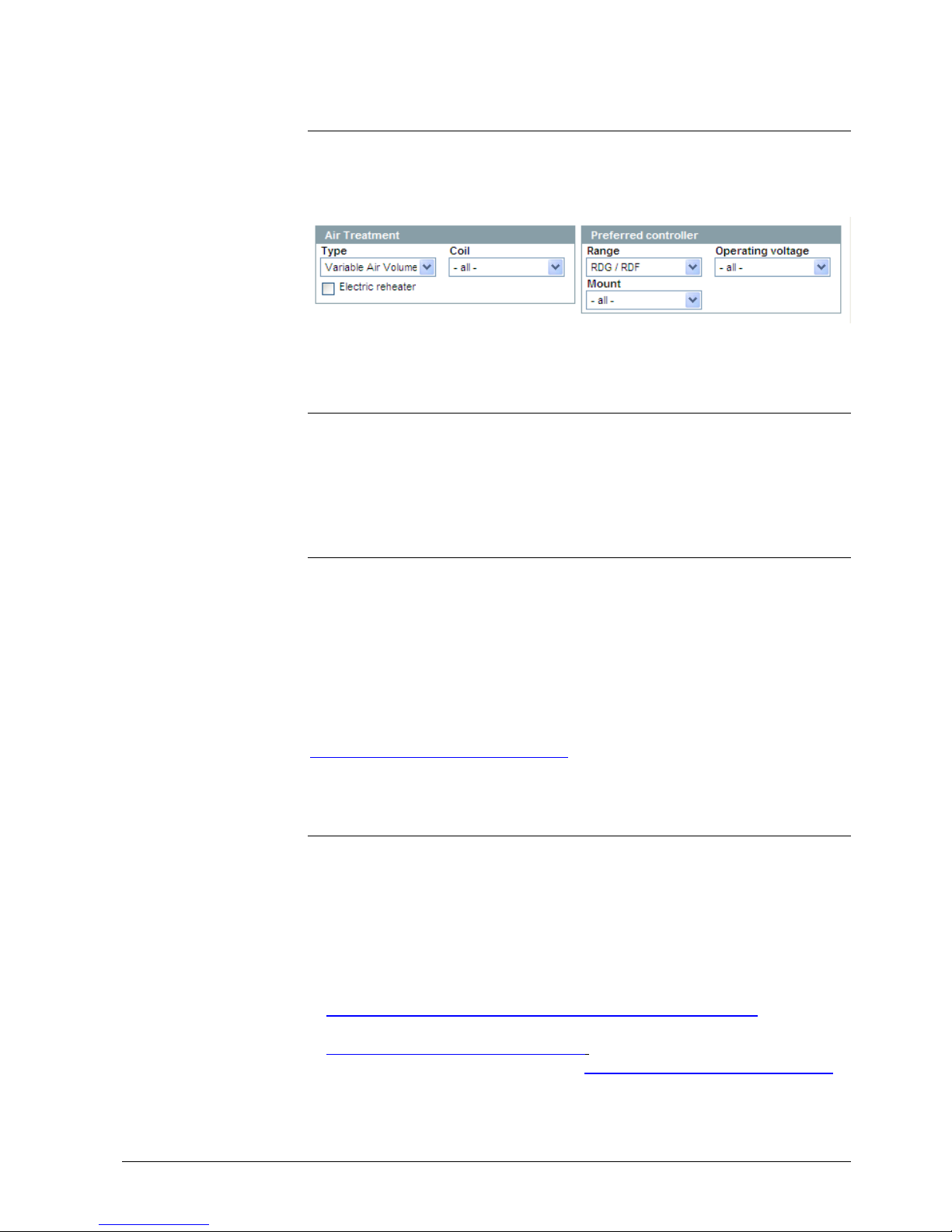
1.3 How to find RDG400KN/RDG405KN
applications in HIT
Select Applications > Individual rooms and set the search criteria as follows:
∂ Air Treatment: Type "Variable Air Volume"
∂ Preferred controller: Range "RDG / RDF"
1.4 Before you start
1.4.1 Copyright
This document may be duplicated and distributed only with the express permission
of Siemens, and may be passed only to authorized persons or companies with the
required technical knowledge.
1.4.2 Quality assurance
This document was prepared with great care.
∂ The contents of this document is checked at regular intervals
∂ Any corrections necessary are included in subsequent versions
∂ Documents are automatically amended as a consequence of modifications and
corrections to the products described
Please make sure that you are aware of the latest document revision date.
If you find lack of clarity while using this document, or if you have any criticisms or
suggestions, please contact the Product Manager in your nearest branch office.
The addresses of the Siemens Regional Companies are available at
www.buildingtechnologies.siemens.com.
1.4.3 Document use/request to the reader
Before using our products, it is important that you read the documents supplied
with or ordered at the same time as the products (equipment, applications, tools,
etc.) carefully and in full.
We assume that persons using our products and documents are authorized and
trained appropriately and have the technical knowledge required to use our
products as intended.
More information on the products and applications is available:
∂ On the intranet (Siemens employees only) at
https://workspace.sbt.siemens.com/content/00001123/default.aspx
∂ From the Siemens branch office near you
www.buildingtechnologies.siemens.com or from your system supplier
∂ From the support team at headquarters fieldsupport-zug.ch.sbt@siemens.com if
there is no local point of contact
Page 6

6 / 87
Siemens RDG400KN,RGD405KN Basic documentation CE1P3192en
Building Technologies 2017-02-17
Siemens assumes no liability to the extent allowed under the law for any losses
resulting from a failure to comply with the aforementioned points or for the
improper compliance of the same.
1.5 Target audience, prerequisites
This document assumes that users of the RDG..KNX room thermostats are familiar
with the ETS and/or Synco ACS tools and are able to use them.
It also presupposes that these users are aware of the specific conditions associated with KNX.
In most countries, specific KNX know-how is conveyed through training centers
certified by the KNX Association (see www.konnex.org/).
For reference documentation, refer to section 1.2.
1.6 Glossary
The inputs, outputs and parameters of an application can be influenced in various
ways. These are identified by the following symbols in this document:
Parameters identified by this symbol are set using the ETS tool.
Parameters identified by this symbol are set using the ACS tool.
Setting RDG..KNX parameters is only supported by the following tool
versions:
– ETS4 or higher
– ACS790
Inputs and outputs identified by this symbol communicate with other KNX devices.
They are called communication objects (CO).
The communication objects of the RDG..KNX room thermostats work partly in
S-Mode, partly in LTE-Mode, and partly in both. These objects are described
accordingly.
A list of the parameters is shown in section 3.12.
ETS
ACS
STOP
Note
KNX
R
Page 7
7 / 87
Siemens RDG400KN,RGD405KN Basic documentation CE1P3192en
Building Technologies 2017-02-17
2. Summary
2.1 Types
Type Features
Operating
voltage
Number of control outputs
Backlit
LCD
On/Off PWM 3-pos
DC
0…10 V
VAV
control via
KNX
LTE-Mode
IAQ
RDG400KN
AC 24 V 1
1)
1
1)
1
1)
1
---
RDG405KN
AC 24 V 1
1)
1
1)
1
1)
1
1) Selectable: On/Off, PWM or 3-position (triac outputs)
2.2 Ordering
Order valve actuators separately.
2.3 Functions
VAV systems via On/Off or modulating control outputs or KNX LTE-Mode:
∂ Single-duct system
∂ Single-duct system with electric heater
∂ Single-duct system and radiator/floor heating
∂ Single-duct system with heating/cooling coil
The room thermostats are delivered with a fixed set of applications.
The required application is selected and activated during commissioning using one
of the following tools:
∂ Synco ACS
∂ ETS
∂ Local DIP switch and HMI
∂ Operating modes: Comfort, Economy (energy saving) and Protection
∂ Output for VAV box/air damper/VAV compact controller: DC 0…10 V/3-position
(triac)/KNX LTE-Mode
∂ Output for heating/cooling coil: On/Off, PWM or 3-position (triac)/DC 0...10 V
∂ Output signal inversion as an option (DC 0...10 V ⇓ DC 10...0 V)
∂ Automatic or manual heating/cooling changeover
∂ Backlit LCD
∂ AC 24 V operating voltage
∂ Indoor air quality (IAQ) control loop with external CO2 /VOC sensor (DC 0...10 V
or KNX LTE- and S-Mode)
∂ Window contact (RDG405KN)
∂ Presence detector (RDG405KN)
∂ Receive temperature via bus (RDG405KN)
∂ Selectable DC input (RDG405KN)
Product No. Stock No. Description
RDG400KN S55770-T165 Room thermostat
RDG405KN S55770-T348 Room thermostat
Use
Features
Page 8

8 / 87
Siemens RDG400KN,RGD405KN Basic documentation CE1P3192en
Building Technologies 2017-02-17
∂ Room temperature control via built-in sensor or external room
temperature/return air temperature sensor or KNX room temperature sensor
∂ IAQ control via external CO2/VOC sensor on the DC 0…10 V inputs KNX (LTE-
or S-Mode)
∂ Changeover between heating and cooling mode (automatically via local sensor
or bus, or manually)
∂ Selection of applications via DIP switches or commissioning tool (ACS790).
∂ Selection of operating mode via operating mode button on the thermostat
∂ Temporary Comfort mode extension
∂ Display of current room temperature or setpoint in °C and/or °F
∂ Display of CO2 external sensor value in ppm or with symbols (+++; ++-; +--)
(RDG405KN)
∂ Display of outside temperature or time of day via KNX bus
∂ Minimum and maximum limitation of room temperature setpoint
∂ Minimum and maximum limitation of air flow signal DC 0...10 V/3-position
∂ External CO2 sensor DC 0…10 V; 0…2000 ppm (RDG405KN)
∂ External CO2 sensor, KNX; 0…5000 ppm (RDG405KN)
∂ Button lock (automatic or manual)
∂ 2 multifunctional inputs, freely selectable for:
– Operating mode switchover contact (keycard, window contact, etc.)
(RDG400KN)
– Window contact switching operating mode to Protection (RDG405KN)
– Presence detector switching operating mode to Comfort (RDG405KN)
– Sensor for automatic heating/cooling changeov er
– External room temperature or return air temperature sensor
– Dewpoint sensor
– Electric heater enable
– Fault input
∂ Interworking with AQR and QMX sensor for IAQ and room temperature
acquisition (RDG405KN)
∂ 1 multifunctional active DC input (RDG405KN), freely selectable for:
- External IAQ sensor (CO2, VOC)
- Air damper position feedback (optimization of supply air fan’s operation)
∂ Monitoring input for temperature sensor or switch state
∂ Feedback of air damper position via KNX bus or a DC 0...10V input for
optimization of pressure control
∂ Floor heating temperature limitation
∂ Reloading factory settings for commissioning and control parameters
Functions
Page 9

9 / 87
Siemens RDG400KN,RGD405KN Basic documentation CE1P3192en
Building Technologies 2017-02-17
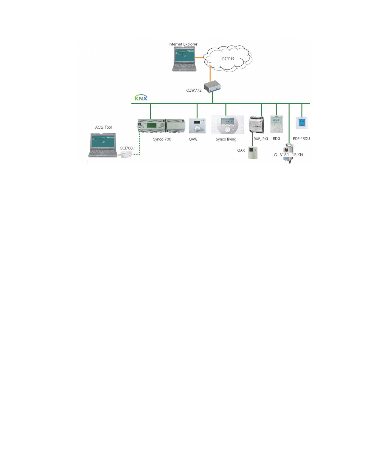
2.4 Integration via KNX bus
The RDG.. room thermostats can be integrated as follows:
∂ Integration into Synco 700 system via LTE-Mode (easy engineering)
∂ Integration into Synco living via group addressing (ETS)
∂ Integration into Desigo via group addressing (ETS) or individual addressing
∂ Integration into third-party systems via group addressing (ETS)
The following KNX functions are available:
∂ Central time program and setpoints, e.g. when using the RMB795 central control
unit
∂ Outside temperature or time of day via bus displayed on the thermostat
∂ Remote operation and monitoring
∂ Remote operation and monitoring with web browser using the OZW772 or
OZW775 web server
∂ Maximum energy efficiency due to exchange of relevant energy information, e.g.
with Synco 700 controllers (e.g. heating/cooling demand, air damper position)
∂ Alarming, e.g. external fault contact, condensation, etc.
∂ Monitoring input for temperature sensor or switch
Engineering and commissioning can be performed using …
– the local DIP switches/HMI
– the Synco ACS tool
– the ETS
The RDG.. room thermostats are especially tailored for integration into the Synco
700 system and operate together in KNX LTE-Mode. This extends the field of use
of Synco for individual room control in connection with fan coil units, VAV, chilled
ceilings and radiators.
Thanks to S-Mode extension to the QAX910 central apartment unit, communicating
room thermostats can be easily integrated into Synco living systems. Using the
S-Mode data points of the central apartment unit, additional room information can
be exchanged with the room thermostat via KNX TP1 (RF function is not available
on the room thermostats). To make the integration, the ETS engineering tool is
required.
Synco 700
Synco living
Page 10
10 / 87
Siemens RDG400KN,RGD405KN Basic documentation CE1P3192en
Building Technologies 2017-02-17
Synco 700 Building automation and control system (BACS)
Synco living Room automation and control system
RDG.., RDF.., RDU.. Room thermostats
OZW772 (or OZW775) Web server
QAW.. Room unit
ACS tool Service tool using OCI702 (OCI702) is delivered with a
service cable which can be plugged into the service
connector on a Synco controller)
RXB, RXL Room controllers
QAX Room unit for RXB/RXL room controllers
G..B181..1E/KN VAV compact controller for KNX LTE-Mode
The RDG..KNX devices can be integrated into the Siemens building automation
and control systems (BACS) Desigo or 3rd-party systems. For integration, either SMode (group addressing) or individual addressing can be used. The workflow for
integration into Desigo is the same as with standard KNX devices.
Synco topology
Legend:
Desigo and third-party
systems
Page 11
11 / 87
Siemens RDG400KN,RGD405KN Basic documentation CE1P3192en
Building Technologies 2017-02-17
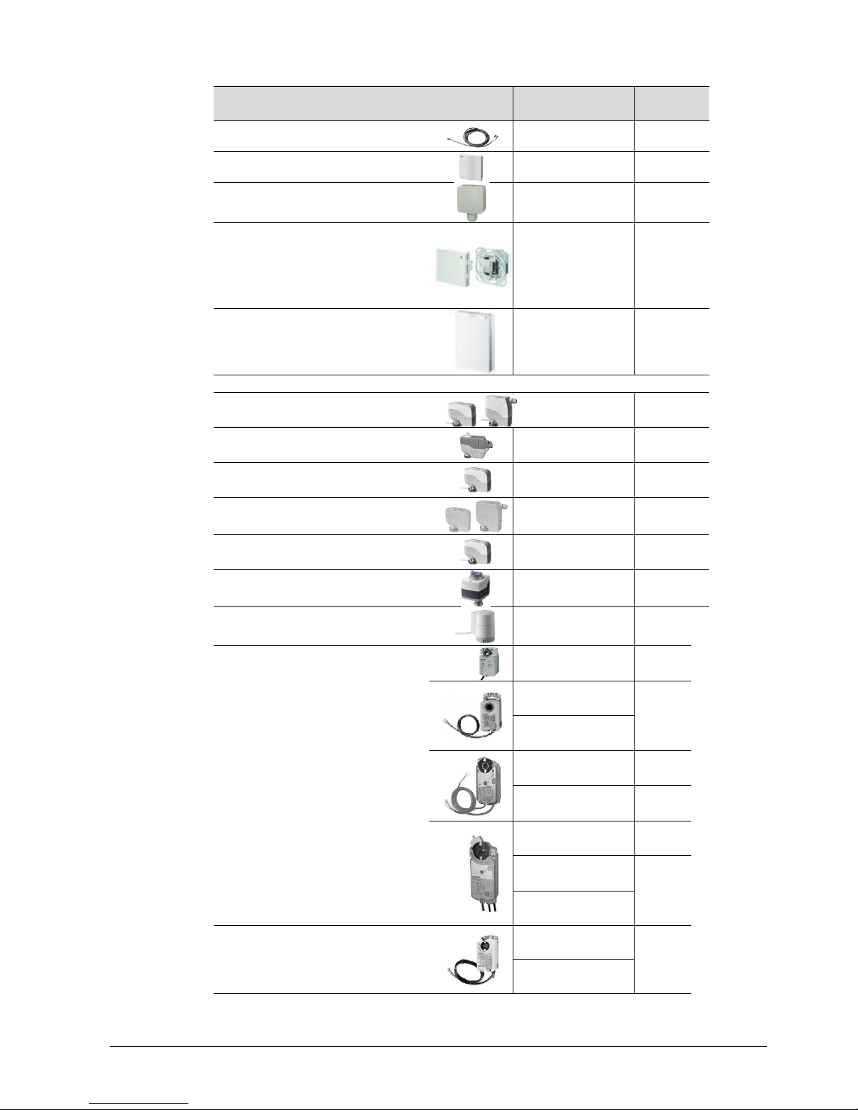
2.5 Equipment combinations
Type of unit Product No.
Data
Sheet
Cable temperature sensor
QAH11.1
1840
Room temperature sensor
QAA32
1747
Condensation monitor
QXA21..
A6V10741072
Flush-mount KNX room sensor
(base and front module)
AQR2576N...
AQR2530NNW
AQR2532NNW
AQR2535NNW
AQR2535NNWQ
1411
Wall-mounted KNX sensors QMX3.P30
QMX3.P70
1602
Electric actuator, DC 0...10 V
(for radiator valve)
SSA61..
4893
Electric actuator, DC 0…10 V
(for 2 and 3 port valves/V..P45)
SSC61..
4895
Electric actuator, DC 0..10 V
(for small valve 2,5 mm V..P47)
SSP61..
4864
Electric actuator, DC 0..10 V
(for small valves 5.5 mm V..P45)
SSB61..
4891
Electric actuator, DC 0..10 V
(for Combi-valve VPI46)
SSA61..
4893
Electromotoric actuator, DC 0...10 V
(for valves 5.5 mm)
SAS61..
4581
Thermal actuator, DC 0…10 V
(for small vlves and radiator valves)
STP63
4884
Damper actuators
DC 0…10 V and 3-position
GQD161..
GQD131..
4605
GDB161..
GDB131..
4634
GLB161..
GLB131..
GMA161..
GMA131..
4614
GEB161..
GEB131..
4621
GCA161..
GCA131..
4613
GBB161..
GBB131..
4626
GIB161..
GIB131..
VAV compact controller
GDB181.1E/3
3544
GLB181.1E/3
Valve actuators
DC 0...10 V
Damper actuators
DC 0...10 V and
3-position,
VAV compact
controllers
Sensors
Page 12
12 / 87
Siemens RDG400KN,RGD405KN Basic documentation CE1P3192en
Building Technologies 2017-02-17
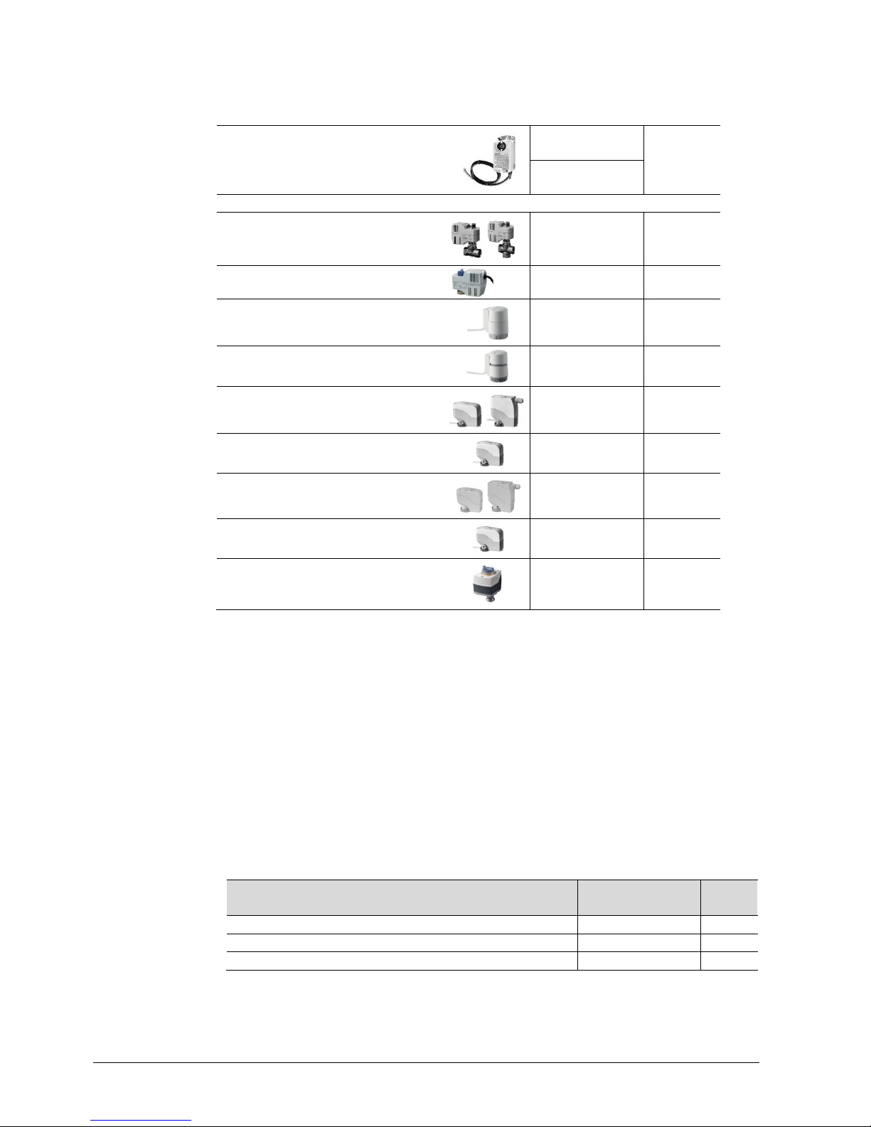
VAV compact controller
for KNX LTE-Mode
GDB181.1E/KN
3547
GLB181.1E/KN
Electromotoric On/Off valve and
actuator
(only available in AP, UAE, SA and IN)
MVI../MXI..
4867
Electromotoric On/Off actuator
SFA71..
4863
Thermal actuator (for radiator
valves)
STA73..
4884
Thermal actuator
(for small valves 2.5 mm)
STP73..
4884
Electric actuator, 3-position
(for radiator valves)
SSA81..
4893
Electric actuator, 3-position
(for small valves 2.5 mm V..P47)
SSP81..
4864
Electric actuator, 3-position
(for small valves 5.5 mm V..P45)
SSB81..
4891
Electric actuator, 3-position
(for CombiValves VPI46)
SSA81..
4893
Electromotoric actuator, 3-position
(for valves 5.5 mm)
SAS81..
4581
* W ith PWM control, it is n ot possible to ensure exact parallel running of more than one thermal actuator. If several
actuators are controlled by the same room thermostat, preference should be given to motorized actuators with
On/Off or 3-position c ontrol
For more information about parallel operation and the maximum number of actuators that can
be used, refer to the Data Sheets of the selected type of actuator and the following listing:
Maximum number of actuators in parallel operation with RDG400KN and RDG405KN:
∂ 6 actuators S..81 (3-position)
∂ 4 actuators ST..73 (On/Off)
∂ 4 actuators SFA.., MVI.., MXI.. (On/Off)
∂ 10 damper actuators G..16.. DC
∂ 6 damper actuators G..13.. (3-position)
2.6 Accessories
Description
Product No/
Stock No.
Data
Sheet
KNX power supply unit 160 mA (Siemens BT LV)
5WG1 125-1AB02
--
KNX power supply unit 320 mA (Siemens BT LV)
5WG1 125-1AB12
--
KNX power supply unit 640 mA (Siemens BT LV)
5WG1 125-1AB22
--
VAV compact controller
KNX LTE-Mode
On/Off/PWM valve
actuators AC 24 V*
3-position valve
actuators
AC 24 V
Note
On/Off valve actuators
AC 24 V
Page 13
13 / 87
Siemens RDG400KN,RGD405KN Basic documentation CE1P3192en
Building Technologies 2017-02-17
3. Functions
3.1 Temperature and IAQ control (RDG405KN
only)
3.1.1 Temperature control
Setting of the control parameters (P01, etc., mentioned throughout the document)
is described in section 3.12.
The thermostat acquires the room temperature via built-in sensor, external room
temperature sensor (QAA32) or external return air temperature sensor (QAH11.1),
and maintains the setpoint by delivering actuator control commands to the heating
and/or cooling equipment. The following control outputs are available:
∂ VAV box/air damper:
Modulating PI/P control with DC 0...10 V/3-position/KNX LTE-Mode
∂ Heating/cooling coil, radiator, electric heater:
Modulating PI/P control with 3-position/PWM/DC 0...10 V/On/Off control
(2-position)
The switching differential or proportional band is 2 K for heating mode and 1 K for
cooling mode (adjustable via P30 and P31).
The integral action time for modulating PI control is
5 minutes for the RDG400KN and 45 minutes for the RDG405KN (adjustable via
P35).
The display shows the acquired room temperature or the Comfort setpoint, selectable via P06. The factory setting displays the current room temperature.
P04 is used to display the room temperature or setpoint in °F rather than °C as
needed.
The acquired room temperature (built-in or external sensor) is also available as
information on the bus.
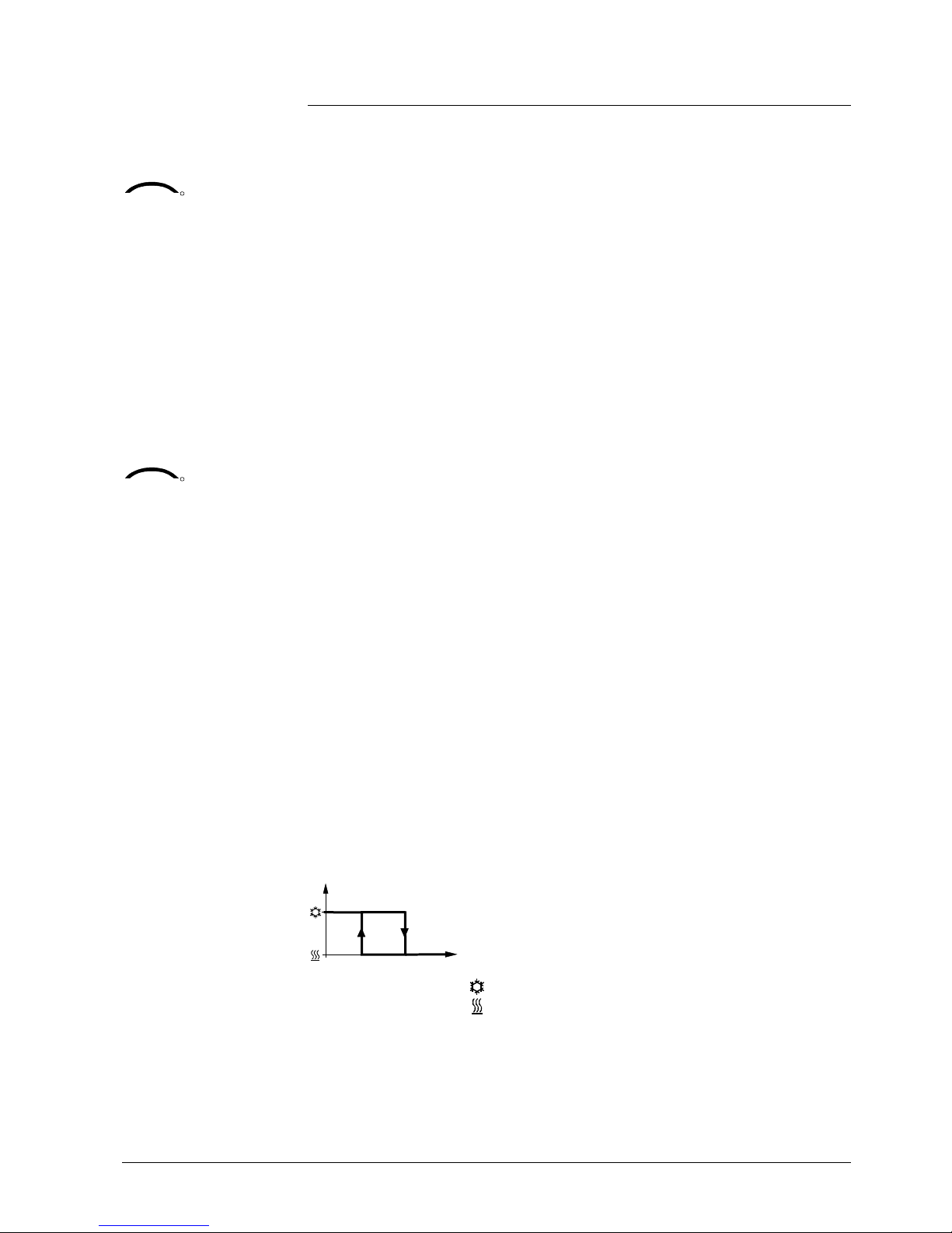
∂ With automatic changeover or continuous heating/cooling, symbols /
indicate that the system currently heats or cools (heating or cooling output
activated)
∂ With manual changeover (P01 = 2), symbols / indicate that the system
currently operates in heating or cooling mode. Thus, the symbols are displayed
even when the thermostat operates in its neutral zone.
Symbols / indicate that the system currently heats or cools (heating or
cooling output activated)
Concurrent display of the current temperature or setpoint in °C and °F (P07 = 1) is
possible on the thermostat.
The outside temperature can be displayed on the room thermostat by setting
P07 = 2. This temperature value has only informative character.
In LTE-Mode, the outside temperature can only be received on outside temperature
zone 31.
Time of day via bus can be displayed on the room thermostat by setting
P07 = 3 or 4. The display is either in 12- or 24-hour format.
The information can be received from a Synco controller with time master
General note:
Parameters
Temperature control
Display
KNX
R
Room temperature
/
Concurrent display of
°C and °F
KNX
R
Outside temperature
via bus
KNX
R
Time of day via bus
Page 14
14 / 87
Siemens RDG400KN,RGD405KN Basic documentation CE1P3192en
Building Technologies 2017-02-17
functionality or any other KNX device if the corresponding communication object is
bound.
When engineering with the ETS tool, the time of day can only be displayed on the
RDG400KN when Synco group address 30/3/254 is loaded into the thermostat.
For further details, refer to Basic Documentation [6], "Communication via KNX-bus
for Synco 700", section "Engineering of big systems with ETS".
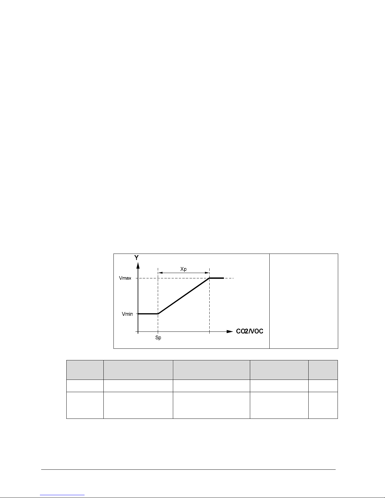
3.1.2 IAQ control (RDG405KN only)
The IAQ function is used for air quality control on VAV applications. The function is
achieved by controlling the air damper position according to the CO2 level of the
indoor air as well as the temperature.
Note that the air damper position is also controlled according to the temperature. It
depends on which is higher, the temperature demand or the CO2 level demand
signal.
The function shall improve the indoor air quality by increasing the volumetric air
flow or VAV output signal respectively.
∂ If the IAQ value of the room is below the preset CO2 setpoint, the VAV
output signal is controlled in accordance with minimum flow
∂ If the IAQ value exceeds the CO2 setpoint, the VAV output signal is
increased slowly until maximum flow is reached
∂ CO2 control is activated in Comfort mode only.
In Economy and Protection mode, this function is disabled
Vmax is reached, when the IAQ value exceeds the preset CO2 setpoint plus the
CO2 proportional band (SP+Xp).
Sp: CO2setpoint [P19]
Xp: CO
2
proportional
band [P20]
Vmin: Minimum flow
Vmax: Maximum flow
Parameter Object Description Values
Factory
setting
P19 CO2 (VOC) setpoint CO2 (VOC) setpoint OFF(0)…5000 ppm 1000
P20 CO2 (VOC) P-band Xp
Proportional band between
Vmin and Vmax
10…2000 ppm 400
Note
General note
Notes
Page 15

15 / 87
Siemens RDG400KN,RGD405KN Basic documentation CE1P3192en
Building Technologies 2017-02-17
∂ P19 can be set up to 5000 ppm but the external analog sensor is limited to
2000 ppm. If there is a need to measure above 2000 ppm, a KNX sensor is
required to send the value with the respective object
∂ P19 = OFF switches the IAQ function off
∂ The IAQ value is acquired either via a locally connected CO2 or VOC
sensor or a CO2 value via bus (e.g. KNX)
Important note for KNX LTE:
IAQ control does not influence in any way the energy demand air, heating or
cooling (in LTE-Mode).
IAQ control – priority CO2 control
∂ If the local CO2 sensor input is configured, the thermostat uses the CO
2
value from the locally connected sensor. Otherwise, the CO2 value
available on KNX is used for CO2 control
∂ In case the local CO2 sensor is configured, but the value is not valid (value
<100 ppm), the thermostat uses the CO2 value via KNX bus.
If both CO2 sources do not deliver a valid value, the CO2 function is
disabled
∂ S-Mode has a higher priority than LTE-Mode
∂ If the CO2 value comes from the bus, the local (DC 0…10 V) value is not
sent on the bus
∂ Receiving and sending the same S-Mode object is not allowed
∂ The thermostat receives the CO2 LTE object when the corresponding
geographical zone is selected
The "Fresh air" symbol appears on the screen as soon as the actual CO
2
value exceeds the CO2 setpoint.
The IAQ level can be shown on the LCD.
3 choices are available:
∂ P07 = 0 No display
∂ P07 = 6 CO2 concentration shown as ppm
∂ P07 = 7 CO2 concentration shown in the form of symbols
Selection P07 = 6: CO2 concentration in ppm
The CO2 concentration is shown on the second line with the ppm symbol.
Minimum display: 100 ppm
Maximum display: 5000 ppm
Display: IAQ function
Parameter
Name
Factory setting
Range
P07 Additional display
information
0 (RDG405KN only) 0 = --- (no display)
1 = °C and °F
2 = outside temperature (via bus)
3 = time of day (12 h) (via bus)
4 = time of day (24 h) (via bus)
6 = CO2 concentration [ppm]
7 = CO2 symbols
Page 16
16 / 87
Siemens RDG400KN,RGD405KN Basic documentation CE1P3192en
Building Technologies 2017-02-17
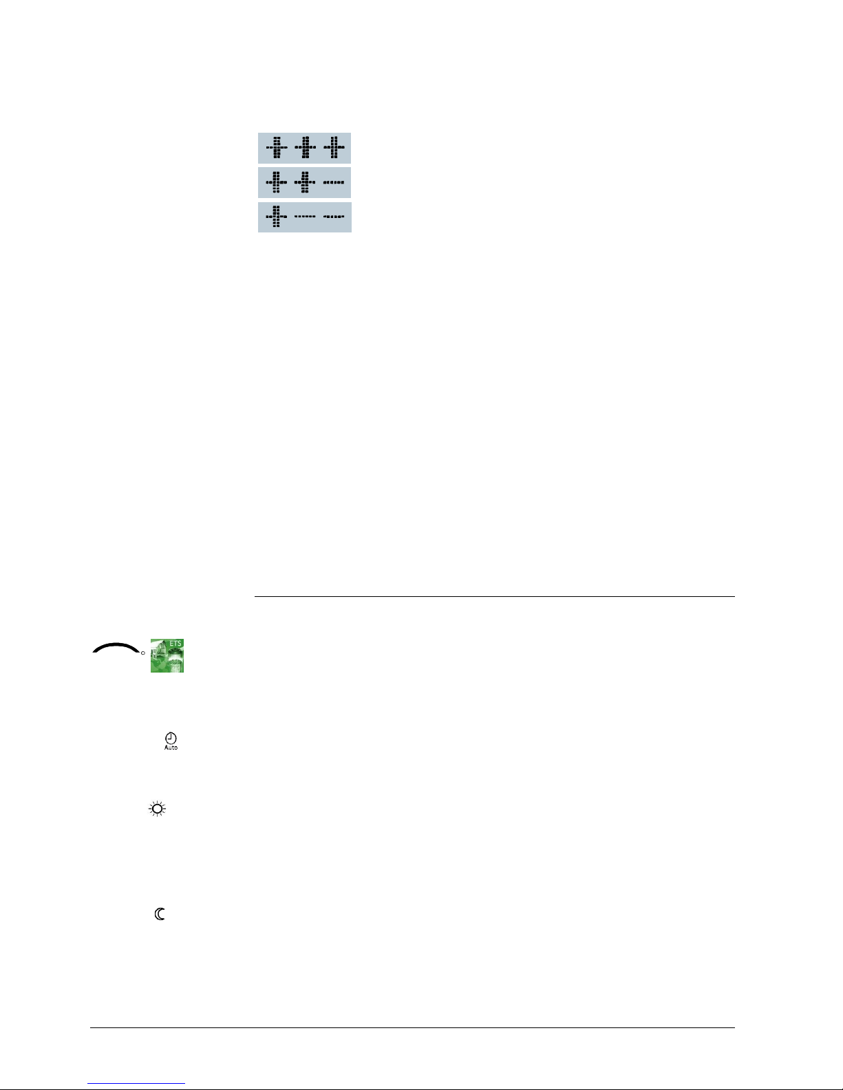
Selection P07 = 7: CO2 symbols
The CO2 concentration is shown on the second line with "+++, ++-, +--". This
parameter can be useful when a VOC sensor is installed.
GOOD: Current CO2 concentration is below the CO2setpoint
OKAY
: Current CO2 concentration is within the CO2 Xp
(proportional band)
POOR
: Current CO2 concentration is above the CO2
setpoint + Xp (proportional band)
When the thermostat is programmed with a CO2 display (ppm or symbols) and no
values are available (no sensor on U1 or no value on KNX), or when the value
received is below 100 ppm, the thermostat displays "---"
IAQ control using a VOC sensor
The VOC sensor can only be connected to the local analog input U1.
Since the thermostat does not distinguish between CO2 or VOC sensor, the IAQ
function and the thermostat’s behavior are the same as for applications with a CO
2
sensor.
For this application, we suggest to keep the default values of setpoint [P19] and
proportional band [P20]. Later, based on the occupant’s feeling, these parameters
can be readjusted for optimum room comfort.
3.2 Operating modes
The thermostat's operating mode can be influenced in different ways (see below).
Specific heating and cooling setpoints are assigned to each operating mode.
The thermostat sends the effective room operating mode on the bus.
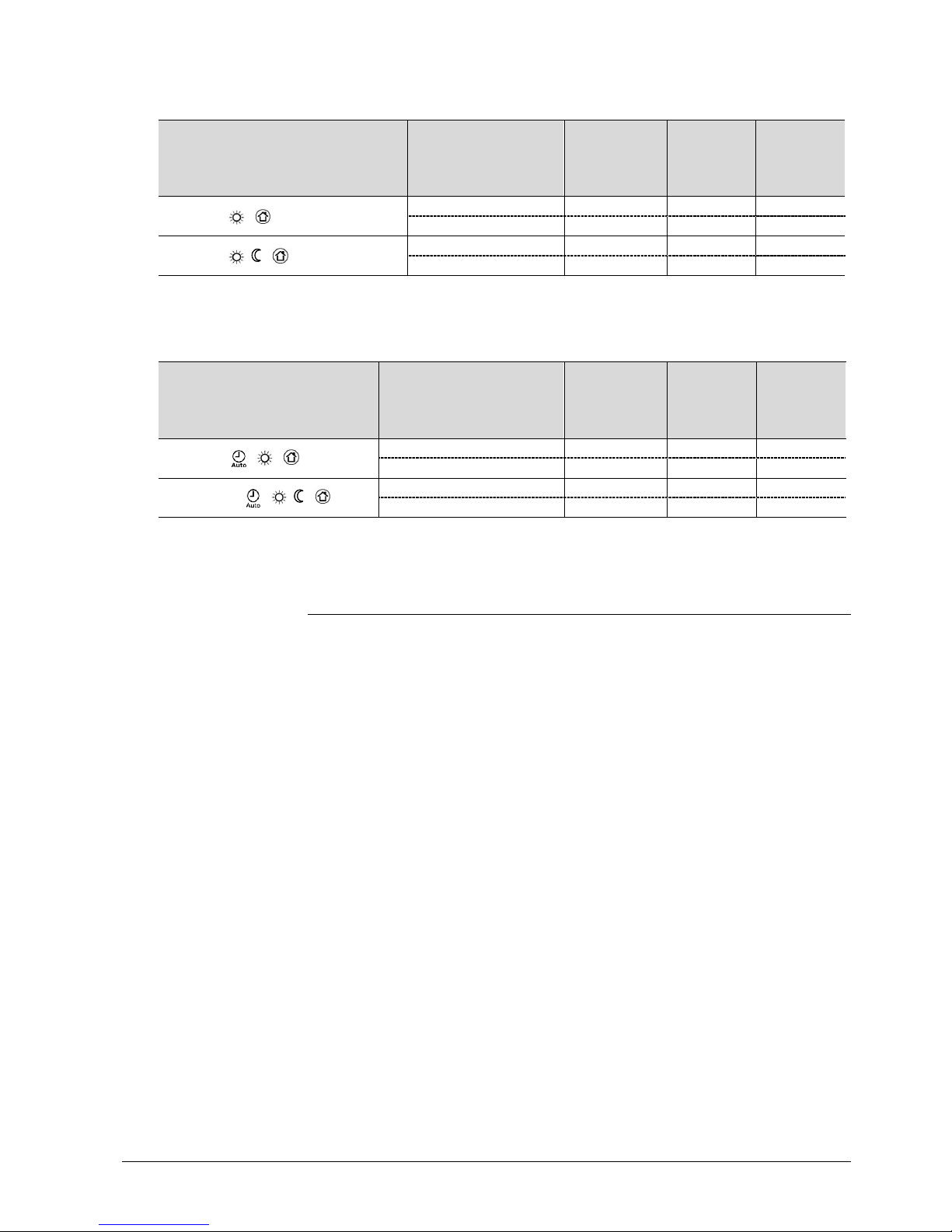
The following operating modes are available:
In Auto Timer mode, the room operating mode is commanded via bus.
Auto Timer mode is replaced by Comfort mode when no time schedule via bus is
present.
In Comfort mode, the thermostat maintains the Comfort setpoint. This setpoint can
be defined via P8, P9 and P10.
It can be locally adjusted via the rotary knob or the bus.
The thermostat switches to Comfort mode when the presence detector (local or via
KNX) is active (room occupied).*)
The setpoints (less heating and cooling than in Comfort mode) can be defined via
P11 and P12.
The thermostat switches to Economy mode when ...
– the operating mode button is pressed (only possible if P02 = 2),
– Economy is sent via bus,
KNX
R
Room operating mode:
State
Auto Timer
Comfort
Economy
KNX presence detector
(RDG405KN)
Page 17

17 / 87
Siemens RDG400KN,RGD405KN Basic documentation CE1P3192en
Building Technologies 2017-02-17
– an operating mode switchover contact (e.g. keycard contact, presence detector,
window contact) is active (for RDG400KN); the contact can be connected to
digital input D1 or multifunctional input X1; set P38/P42 to 3 (P02 is irrelevant) *)
(for RDG400KN)
– "Window state" is sent via bus, e.g. from a KNX switch or a KNX presence
detector (P02 is irrelevant) *) (for RDG400KN)
*) Operating mode switchover: O nly one input source must be used, either local input X1-D1or the
KNX bus. User operations are ineffective and OFF is displayed if the operating mode switchover
contact is active, or if "Window state" is sent via bus
In Protection mode, the system is ...
– protected against frost (factory setting 8 °C, can be disabled or changed via
P65),
– protected against overheating (factory setting OFF, can be enabled or changed
via P66).
No other operating mode can be selected locally if Protection mode is commanded
from the time schedule via bus (e.g. from RMB795). and are displayed.
The thermostat switches to Protection mode when …
– the operating mode button is pressed,
– Protection mode is sent via bus,
– the window contact on the RDG405KN is active (open window),
– "Window state" is sent to the RDG405KN via bus (e.g. from a KNX switch) *)
*) For details r egarding the operating mode switchover contact (RD G40..KN), window contact
(RDG405KN) and presence detector (RDG405KN), refer to section 3.2.1.
KNX
R
Room operating mode:
Window state
(RDG400KN)
Note
Protection
Note
KNX room operating
mode: Window state
(RDG405KN)
Page 18
18 / 87
Siemens RDG400KN,RGD405KN Basic documentation CE1P3192en
Building Technologies 2017-02-17
3.2.1 Different ways to influence the operating mode
The operating mode can be influenced by different interventions.
The source of the effective room operating mode state can be monitored using the
"Cause" diagnostic data point in the ACS tool, or OZW772 web server.
Source
Description
Value of DP "Cause"
Local operation
via left button
∂
Operating mode is not Auto Timer
∂ No time schedule via bus
Room operating mode selector
(preselection)
∂
Temporary Comfort extension is active
"Timer" function
∂
Operating mode switchover contact (RDG400KN)
Room operating mode contact
∂
Window contact (RDG405KN)
Window switch
∂
Presence detector (RDG405KN)
Presence detector
Bus command
KNX
R
Room operating
mode
∂
Window state sent via bus (RDG400KN)
Room operating mode contact
∂
Window state sent via bus (RDG405KN)
Window switch
∂
Presence detector sent via bus (RDG405KN)
Presence detector
∂
Time schedule available via bus
⇓ local operating mode is set to "Auto Timer"
∂ Time schedule sends Protection mode via bus
⇓ operating mode cannot be changed locally
Time switch
The following table shows the priorities of different interventions.
Lower number means higher priority.
Priority
Description
Remark
•
Commissioning In parameter setting mode (highest priority), you can always
command an operating mode independent of all other settings or
intervention via bus and local input.
‚
Protection mode via bus
from time schedule
Protection mode sent by a time schedule has priority 2.
It cannot be overridden by the user nor by an operating mode
switchover contact.
ƒ
Operating mode
switchover contact
(RDG400KN)
If the contact is closed, the operating mode changes to Economy.
This overrides the operating mode on the thermostat.
ƒ
Window contact
(RDG405KN)
If the contact is closed, the operating mode changes to
Protection. This overrides the operating mode on the thermostat.
ƒ
"Window state" via bus "Window state" sent via bus has the same effect as the operating
mode switchover contact (RDG400KN) or local window contact
(RDG405KN).
Note: Only one input source must be used, either the local input
X1-D1 or the KNX bus.
„
Operating mode button The user can change the operating mode using the operating
mode button.
„
Operating mode via bus The operating mode can be changed via bus.
„
Temporary extended
Comfort mode via
operating mode button
The operating mode can be temporarily set from Economy to
Comfort by pressing the operating mode button, if ...
– Economy mode was sent via bus,
– extended Comfort mode period >0 (P68)
The last intervention wins, either locally or via bus.
„
Time schedule via bus The operating mode sent via bus can be overridden by all other
interventions. Exception: Protection mode has priority 2.
„
Presence detector
(RDG405KN)
If the contact is closed (room occupied), the operating mode
changes to Comfort. This overrides the operating mode on the
thermostat. An open contact (room unoccupied) sets the
thermostat back to the previous operating mode.
„
Presence detector via
bus (RDG405KN)
"Presence detector" sent via bus has the same effect as the
local presence detector.
Note:
Only one input source must be used,
either
the
local
input
X1-D1or the KNX bus.
Source for change of
operating mode
ACS
Priority of operating
mode interventions
Page 19
19 / 87
Siemens RDG400KN,RGD405KN Basic documentation CE1P3192en
Building Technologies 2017-02-17
If a time schedule via bus is present (e.g. from the central control unit), Auto Timer
mode is active. In that case, the thermostat changes automatically between
Comfort and Economy mode according to the time schedule via bus.
The display shows the Auto Timer mode symbol along with the symbol for the
effective room operating mode (Comfort or Economy ).
By pressing the operating mode button, another operating mode can be selected.
Each time the time schedule sends a new operating mode (switching event), the
operating mode of the thermostat is set back to Auto Timer mode. This is to ensure
that the room temperature is maintained according to the time schedule.
If the time schedule sends Precomfort mode, this mode changes either to
Economy (factory setting) or Comfort (selectable via P88).
No intervention is possible neither by the user nor by an operating mode switchover contact, if Protection mode is set by the time schedule. OFF blinks on the
display when the user presses a button.
The operating mode can be selected locally via the operating mode button.
The behavior of the operating mode button (user profile) can be defined via P02
(factory setting is P02 = 1).
P02 Without time
schedule
With time
schedule via bus
Description
1 ⇓
⇓
∂ Switching manually between 2 modes, Economy is not
available (factory setting)
∂ Suited for hotel guest rooms or commercial buildings
∂ If a time schedule via bus is available, Comfort mode can
be temporarily extended (see below)
2 ⇓⇓
⇓ ⇓⇓
∂ Switching manually between 3 modes
∂ Suited for homes and rooms where manual switching to
Economy mode is desired
The thermostat can be forced into Economy mode (e.g. when a window is opened,
when a presence detector signals "No one present", when the keycard of a hotel
room is withdrawn, etc). The contact can be connected to digital input D1 (or
multifunctional input X1). Set P42 (P38) to 3.
If the operating mode switchover contact is active, pressing the left button will show
OFF (blinking).
The thermostat is forced into Protection mode when the window is open. The
contact can be connected to multifunctional input X1 or digital input D1. Set P38 or
P42 to 3. User operations are ineffective and OFF displays if the window contact is
active.
The function is also available via the KNX signal "Window state", e.g. from a KNX
switch or a KNX presence detector.
Note: Only one input source must be used, either local input X1-D1or the KNX bus.
User operations are ineffective and OFF is displayed if the operating mode switchover contact is active, or if "Window state" is sent via bus.
Behavior when bus
sends new operating
mode
Precomfort via bus
Behavior when bus
sends Protection
Availability of Economy
mode
Operating mode
switchover contact
(window contact)
(RDG400KN)
Window contact
(RDG405KN)
KNX
R
Room operating mode:
Window state
Auto Timer mode
with time schedule
via bus
Page 20
20 / 87
Siemens RDG400KN,RGD405KN Basic documentation CE1P3192en
Building Technologies 2017-02-17
The operating mode can be changed to Comfort or Economy based on room
occupancy (room occupied or unoccupied, via presence detector or keycard).
Time schedule
via bus
Presence detector behavior
Comfort mode
∂
Whenever the presence detector is activated or deactivated,
Comfort mode is maintained
Economy mode
∂
Whenever the presence detector is activated, the operating
mode changes to Comfort
∂ Whenever the presence detector is deactivated, the
operating mode changes to Economy (with Auto mode)
Protection mode
∂
Presence detector has no impact on the operating mode
Not available
∂
Whenever the presence detector is activated, the operating
mode changes to Comfort
∂ Whenever the presence detector is deactivated, the
operating mode changes to Economy
∂ When the time switch changes to Economy, but the presence detector is still
active, Comfort mode is maintained until the presence detector becomes
inactive
∂ The contact (e.g. a card reader) can be connected to multifunctional input X1
or digital input D1 (set P38 or P42 to 10) or the occupancy is sent via bus from
a KNX presence detector (only one input source must be used, either local
input X1-D1 or the KNX bus)
Comfort mode can be temporarily extended (e.g. working after business hours or
on weekends) when the thermostat is commanded to Economy mode by a central
time switch, operating mode switchover via KNX or via local input X1-D1.
The operating mode button switches the operating mode back to Comfort for the
period preset via P68.
Press the operating mode button again to stop the timer.
The following conditions must be fulfilled:
∂ Mode selection via operating mode button is set to "Protection-Auto" (P02 = 1)
and P68 (extend Comfort period) is greater than 0
∂ The time schedule via bus is Economy or operating mode switchover is active
During the temporary Comfort mode extension, symbol appears.
If P68 (extend Comfort period) = 0, extended Comfort cannot be activated;
pressing the left button switches the thermostat to Protection mode.
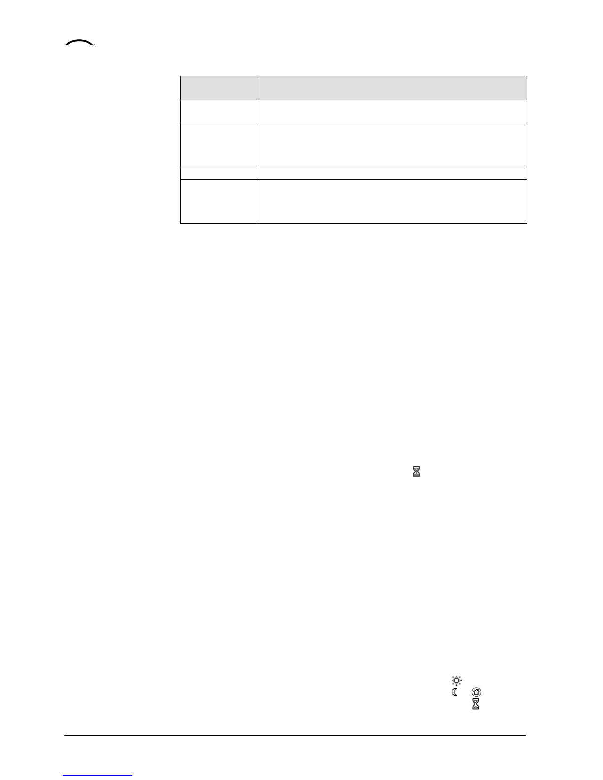
The effective room operating mode can be forced temporarily into Comfort or
Economy/Protection mode. The time period is adjusted via the rotary knob:
∂ Extend presence: Set the device to Comfort mode for the selected time period
∂ Extend absence: Set the device to Economy/Protection mode for the selected
time period
To activate the function, keep the left button pressed and, within 3 seconds, turn
the rotary knob …
∂ clockwise for extended presence,
∂ counterclockwise for extended absence.
The rotary knob adjusts the time period:
∂ Extend presence: 0:00…+9:30 in steps of 30 minutes; symbol appears
∂ Extend absence: 0:00…–9:30 in steps of 30 minutes; symbol or appears
During the extended presence/absence period, the sandglass symbol appears.
KNX
R
Presence detector
(RDG405KN)
Notes
Temporary timer to
extend Comfort mode
Timer for extension of
presence/absence
Page 21
21 / 87
Siemens RDG400KN,RGD405KN Basic documentation CE1P3192en
Building Technologies 2017-02-17
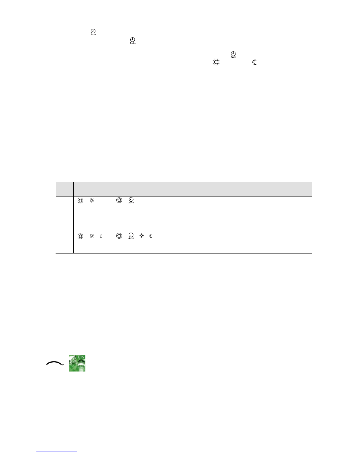
Function if no time schedule is received via bus
User profile for operating mode
(selected via P02)
Operating mode
when activating
function
Function Operating
mode
during
function
Operating
mode at
the end of
function
P02 = 1:
Comfort Extension Comfort Protection
Comfort Absence Protection Comfort
P02 = 2:
Comfort or Economy Extension Comfort Economy
Comfort or Economy Absence Economy Comfort
Extension/absence functions are not available in Protection mode.
Function with time schedule via bus
User profile for operating
mode
(selected via P02)
Operating mode when
activating function
Function Operating
mode
during
function
Operating
mode at
the end of
function
P02 = 1:
Auto or Comfort Extension Comfort Auto
Auto or Comfort Absence Protection Auto
P02 = 2 ⇓
Auto, Comfort or Economy Extension Comfort Auto
Auto, Comfort or Economy Absence Economy Auto
Extension/absence functions are not available in Protection mode.
3.2.2 Communication examples
The following examples show 2 typical applications of a central time schedule in
connection with local control of the room operating mode.
The room operating mode in rooms 1…2 of a building is determined by the time
schedule. Window contacts are fitted in all rooms.
The following conditions are specified:
The rooms are used and controlled by the time schedule as follows:
– Night setback from 17:00 to 08:00 (Economy)
– Protection from 20:00 to 06:00
– Lunch break from 12:00 to 13:00 (Precomfort)
The substitution (P88) for Precomfort via bus is set on the thermostat as follows:
– Room 1: Comfort (1)
– Room 2: Economy (0)
Note
Note
Page 22
22 / 87
Siemens RDG400KN,RGD405KN Basic documentation CE1P3192en
Building Technologies 2017-02-17
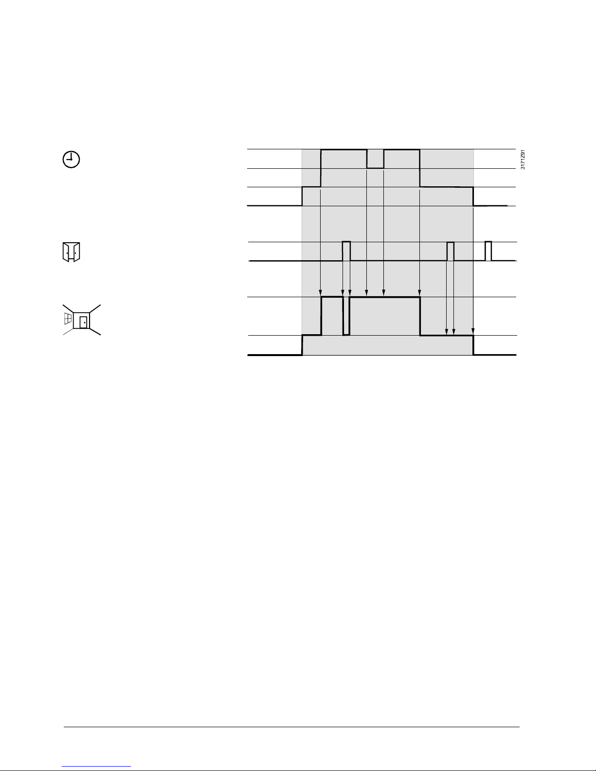
Operating mode switchover
In room 1, the window is opened briefly, once in the morning, once in late
afternoon and once at night (1). Only the opening in the morning has a direct
impact on the effective room operating mode.
During lunch break, the time schedule changes to Precomfort. Comfort mode is
maintained as set via parameter "Transformation Precomfort" (P88 = 1).
Time schedule
Window contact
Room 1
Effective room
operating mode
Room 1
Comfort
Precomfort
Economy
Protection
Window open
Window closed
Comfort
Economy
Protection
08:00
17:00
13:00
12:001)06:00
20:00
1)
1)
2)
Example 1 (RDG400KN)
Page 23
23 / 87
Siemens RDG400KN,RGD405KN Basic documentation CE1P3192en
Building Technologies 2017-02-17
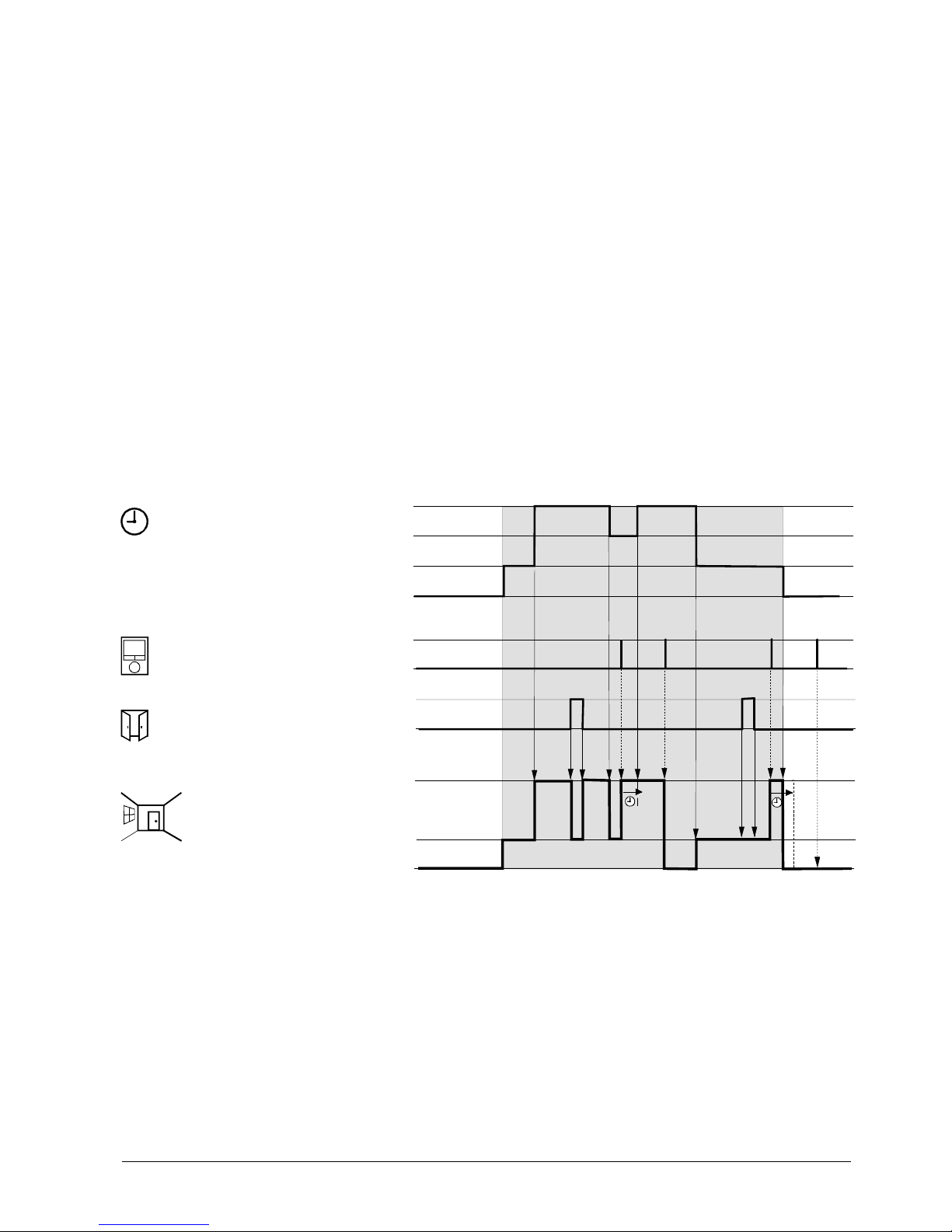
Interaction of user operation (operating mode button) and central time
schedule
In room 2, the window is opened briefly, once in the morning and once at night (1).
Only the opening in the morning has a direct impact on the effective room operating mode.
With the operating mode button, the operating mode can be changed between
OFF and Auto or temporary Comfort extension respectively.
∂ During lunch break, the time schedule changes to Precomfort.
The operating mode of the thermostat changes to Economy as set by
parameter "Transformation Precomfort" (P88 = 0) (6)
∂ During lunch break, the user changes the operating mode to Comfort
(temporary Comfort extension) by pressing the operating mode button (2).
At 13:00, the timer is reset due to mode change of the central time schedule
∂ In the afternoon, the user switches the thermostat off by pressing the operating
mode button (3). At 17:00, the user setting is reset to Economy by the time
schedule
∂ At 19:30, the user again extends the Comfort mode (4). At 20:00, the timer is
reset by the time schedule
∂ After 20:00, pressing the operating mode button has no effect, as the central
time switch sets the thermostat to Protection mode (5)
Time schedule
Room operating
mode
Operating mode
button on the
therm ostat
Window contact
Room 2
Effective room
operating mode
Room 2
Comfort
Precomfort
Economy
Protection
Pressed
Window open
Window closed
Comfort
Economy
Protection
08:00
17:0013:0012:00
06:00
20:00
1)
1)
5)
2)
3)
4)
6)
3171Z92
Example 2 (RDG400KN)
Page 24
24 / 87
Siemens RDG400KN,RGD405KN Basic documentation CE1P3192en
Building Technologies 2017-02-17
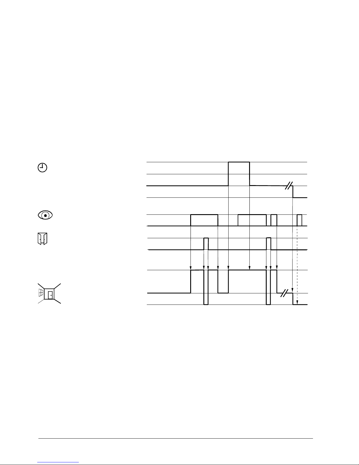
Application for "Window contact", "Presence detector" and "Central time
schedule"
In room 3, the time schedule switches to Comfort mode between 13:00 and 17:00.
∂ In the morning, as soon as presence is detected, the operating mode switches
to Comfort (1)
∂ The users open the window for a short time and the operating mode switches
to Protection (2)
∂ In the afternoon, the central time schedule sets the Comfort mode from 13:00
to 17:00 (3)
∂ After 17:00, the room is still occupied and Comfort mode is maintained
(occupancy via presence detector) (4)
∂ The users open the window and exit the room for a short time. The operating
mode switches to Protection as long as the window is open (5)
∂ As soon as the room is unoccupied, the thermostat switches to Economy (6)
After this time period, the occupancy detected by the presence detector has no
effect, and the central time schedule sets the thermostat to Protection mode (7).
Time schedule
Room operating
mode
Presence
detector
Window contact
Room 3
Actual room
operating mode
Room 3
Comfort
Precomfort
Economy
Protection
(holidays or
special days)
Occupied
Unoccupied
Window open
Window closed
Comfort
Economy
Protection
7)
08:00
17:00
13:00
12:00
5)
4)
1)
3)
3
171Z9
2_0
1
6)
2)
Example 3 (RDG405KN)
Page 25
25 / 87
Siemens RDG400KN,RGD405KN Basic documentation CE1P3192en
Building Technologies 2017-02-17
3.3 Room temperature setpoints
3.3.1 Description
The factory setting for the Comfort basic setpoint is 21 °C and can be changed in
the thermostat’s EEPROM via P08 or via bus with communication object "Comfort
basic setpoint". The last intervention always wins.
For applications with heating and cooling sequence and a dead zone greater
than 0 °C, the basic Comfort setpoint always remains the reference for the heating
sequence.
However, the Comfort setpoint is either the heating setpoint or the cooling setpoint
according to the active sequence (heating or cooling). See also the table in section
3.3.2 and hysteresis behavior, section 3.6.2.
The current setpoint also appears on the RDG..’s display. It can be adjusted via the
rotary knob, or via bus from a remote device like a touch panel, operating unit, etc.
The last intervention always wins.
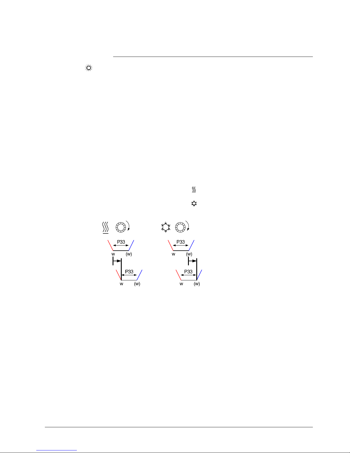
The thermostat also shows the symbol of the active sequence while the rotary
knob is turned:
– Setpoint and heating symbol ( ) show that the Comfort setpoint "Heating" is
being adjusted
– Setpoint and cooling symbol ( ) show that the Comfort setpoint "Cooling" is
being adjusted
3192z11
P33
w
(w)
Dead zone
Setpoint heating sequence
Setpoint cooling sequence
Adjusting the Comfort setpoint via rotary knob causes a shift of the dead zone.
Although only one setpoint shows on the RDG..’s display, both setpoints are
shifted by the same value.
If the "Temporary setpoint" function is enabled via P69, the Comfort setpoint
adjusted via the rotary knob, or via bus, is set back to the Comfort basic setpoint
stored in P08 when the operating mode changes.
For comfort or energy saving purposes, the setpoint setting range can be limited to
minimum (P09) and maximum (P10).
∂ If the minimum limit P09 is set lower than the maximum limit P10, both heating
and cooling are adjustable between these 2 limits
∂ The customer adjusts the desired setpoint and the thermostat controls the room
temperature accordingly
Comfort mode
Setpoint adjustment
Temporary setpoint
Setpoint limitation
P09 < P10
(comfort concept)
Page 26

26 / 87
Siemens RDG400KN,RGD405KN Basic documentation CE1P3192en
Building Technologies 2017-02-17
Example
5癈 40癈25癈18癈
P10P09
Cooling setpoint adjustable: 18…25 °C
Heating setpoint adjustable: 18…25 °C
∂ If the minimum limit P09 is set higher than the limit P10, …
– the setting range of the cooling setpoint is from P09…40 °C in place of
5…40 °C,
– the setting range of the heating setpoint is from 5…P10 °C in place of
5…40 °C.
This allows the user to limit the maximum heating setpoint and the minimum
cooling setpoint. This concept helps save energy costs.
∂ For heating OR cooling applications:
– The thermostat operates with the setpoint of the active sequence:
In heating mode, the heating setpoint is active and adjustable via the rotary
knob. In cooling mode, the cooling setpoint is active and adjustable via the
rotary knob
– Switching from the heating to the cooling setpoint and vice versa occurs
when the room temperature reaches the adjusted limitation (P09 or P10) of
the inactive sequence (e.g. the thermostat is in the heating sequence and
runs with the heating setpoint). When the room temperature reaches P09,
the thermostat switches to cooling mode and runs with the cooling setpoint
as long as the room temperature does not drop below P10
Example
5癈 40癈25癈21癈
P09P10
Cooling setpoint adjustable: 25…40 °C
Heating setpoint adjustable: 5…21 °C
Use P11 and P12 to adjust the Economy mode setpoints.
The heating setpoint is factory-set to 15 °C, and the cooling setpoint to 30 °C.
Use P65 and P66 to adjust the Protection mode setpoints.
The heating setpoint is factory-set to 8 °C (frost protection) and to OFF for cooling.
If a setpoint (Economy or Protection) is set to OFF, the thermostat does not control
the room temperature in the corresponding mode (heating or cooling).
This means no protective heating or cooling function and thus risk of frost in
heating mode or risk of overtemperature in cooling mode!
The Economy setpoints are accessible at the Service level (P11, P12), the
Protection setpoints at the Expert level (P65, P66).
P09 ≥ P10
(energy saving concept)
Economy mode
Protection mode
Caution
Page 27
27 / 87
Siemens RDG400KN,RGD405KN Basic documentation CE1P3192en
Building Technologies 2017-02-17
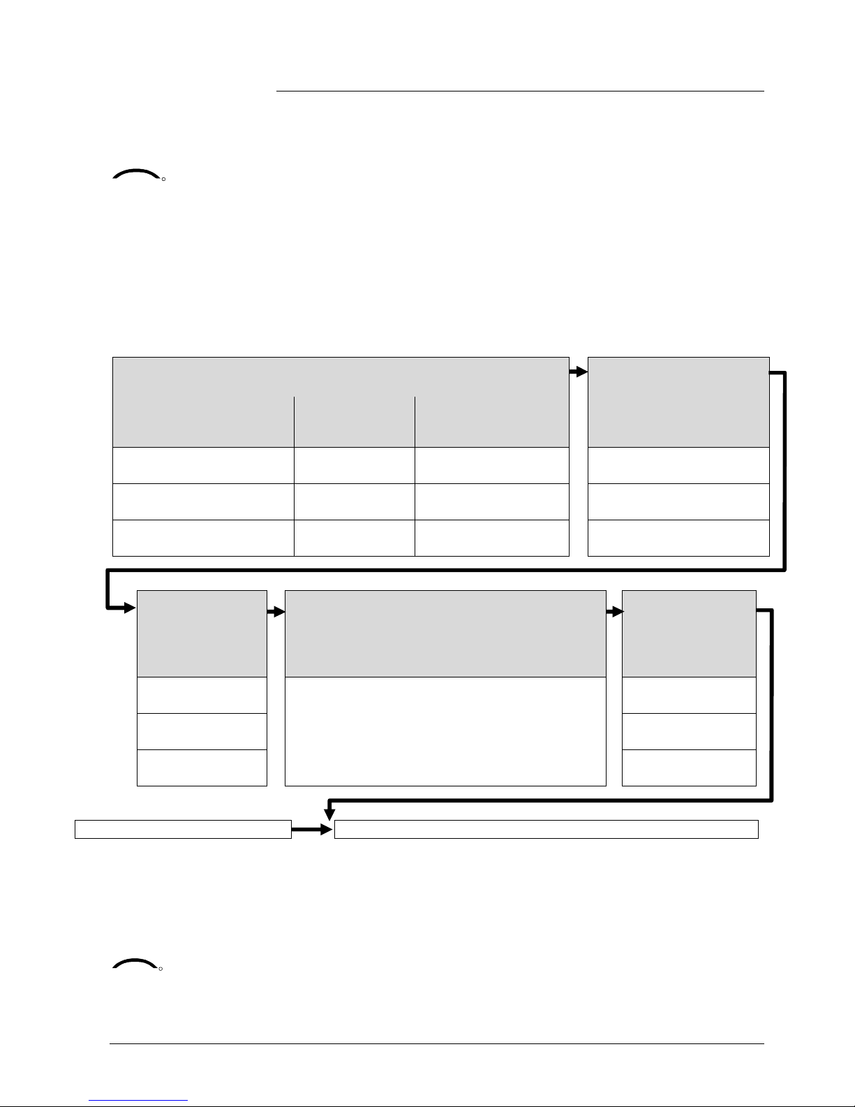
3.3.2 Setting and readjusting setpoints
Room temperature setpoints can be …
– set during commissioning,
– readjusted during operation.
The source can be …
– the local HMI,
– a tool,
– a central control unit.
The thermostat stores the setpoints …
– in EEPROM in the form of parameters,
– in the runtime memory.
The table below shows the interrelations:
Setpoint setting
Stored in EEPROM
of thermostat
Commissioning
– HMI
– Tool download
Input LTE-Mode Input S-Mode
Comfort basic setpoint
Dead zone Comfort
1)
Setpoints Heating
Setpoints Cooling
Comfort basic setpoint
P08 Comfort basic setpoint
P33 Dead zone Comfort
1)
Setpoint Economy Heating
Setpoint Economy Cooling
Setpoints Heating
Setpoints Cooling
Setpoints Heating
Setpoints Cooling
P11 Economy Heating
P12 Economy Cooling
Setpoint Protection Heating
Setpoint Protection Cooling
P65 Protection Heating
P66 Protection Cooling
Current runtime
setpoints in
thermostat
Setpoint adjustment
New current
runtime setpoints
in thermostat
Input LTE-Mode
2)
Input S-Mode
3)
Local operation
3)
Comfort setpoint
Setpoint shift H
Setpoint shift C
Comfort setpoint Rotary knob Comfort setpoint
Economy Heating
Economy Cooling
Setpoint shift H
Setpoint shift C
Economy Heating
Economy Cooling
Protection Heating
Protection Cooling
Protection Heating
Protection Cooling
Effective room operating mode Current setpoint (used by the thermostat for temperature control)
1) Only required f or heating AND cooling applications (see section 3.6.9)
2) The shift is added to the local shift (LTE-Mode only)
3) The last int ervention wins, either S-Mode input or local oper ation
4) To display the S-Mode objects of the Ec onomy heating and cooling setpoint (P11, P12), s et the
control parameter "Room temperatu re: Economy setpoints" to as group object in the ETS tool
The current setpoint (used by the thermostat for temperature control) is available
on the bus for use in the central control unit.
KNX
R
Comfort basic setpoint
Comfort setpoint
Economy heating
setpoint
4)
Economy cooling
setpoint
4)
KNX
R
Current setpoint
Page 28

28 / 87
Siemens RDG400KN,RGD405KN Basic documentation CE1P3192en
Building Technologies 2017-02-17
∂ The supported communication objects differ in LTE- and S-Mode
∂ Changes via the local HMI or via KNX have the same priority (last always wins)
∂ Adjusting the Comfort basic setpoint resets the runtime Comfort setpoint to the
basic setpoint
∂ Central setpoint shift is used for summer/winter compensation in particular
∂ Setpoint shift does not affect the setpoints stored in P08, P11, P12 and P33
∂ Local shift and central shift are added together
∂ Applies only to Comfort and Economy setpoints; Protection setpoints are not
shifted centrally
∂ The resulting (current) setpoint heating and cooling is limited by the Protection
setpoint; if the Protection setpoint is OFF, minimum 5 °C and maximum 40 °C
are used
∂ The resulting setpoints for cooling and heating of the same operating mode have
a minimum distance of 0.5 K between them
∂ The result of local and central shift, together with the room operating mode, is
used by the thermostat for temperature control (current setpoint)
General notes
Notes on setpoint
adjustment (LTE-Mode
with Synco only)
Page 29
29 / 87
Siemens RDG400KN,RGD405KN Basic documentation CE1P3192en
Building Technologies 2017-02-17
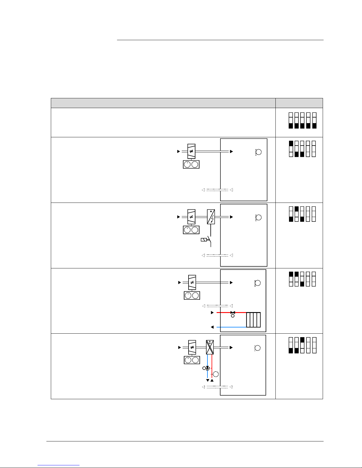
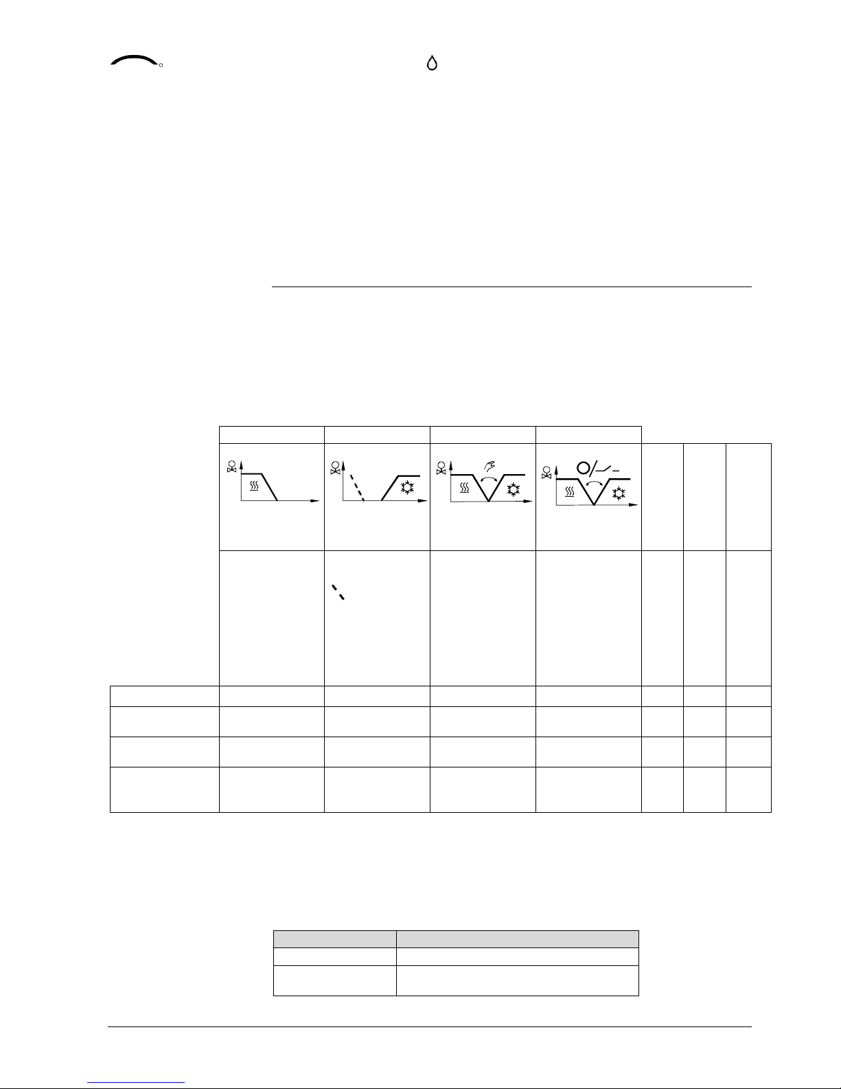
3.4 Applications overview
The room thermostats support the following applications, which can be configured
using the DIP switches at the rear of the unit or a commissioning tool.
DIP switches 1...5 must be set to OFF (remote configuration, factory setting) to
select an application via commissioning tool. In this case, the output signal type
needs to be set in the ACS tool as well.
The tool offers the applications printed in bold text (basic applications).
Application DIP switches
Remote configuration
Via commissioning tool (factory setting)
∂ Synco ACS
∂ ETS
1ON2 3
OFF
4 5
Single-duct
∂ DC 0…10 V damper actuator (P47 = 0)
∂ 3-position damper actuator (P47 = 1)
∂ VAV compact controller KNX LTE mode
3192S07
B1
T
MV MV
YV
1ON23
OFF
4 5
Single-duct with electric heater
∂ DC 0…10 V damper actuator and On/Off,
PWM or 3-position electric heater (P47 = 0)
∂ 3-position damper actuator and
DC 0…10 V electric heater (P47 = 1)
∂ VAV compact controller KNX LTE-Mode
and electric heater
3192S08
YE
B1
T
MV MV
YV
1ON2 3
OFF
4 5
Single-duct and radiator/floor heating
∂ DC 0…10 V damper actuator and On/Off,
PWM or 3-position radiator (P47 = 0)
∂ 3-position damper actuator and
DC 0…10 V radiator (P47 = 1)
∂ VAV compact controller KNX LTE-Mode
and radiator
3192S09
MV MV
YV
YR
B1
T
1ON2 3
OFF
4 5
Single-duct heating and cooling coil
∂ DC 0…10 V damper actuator and On/Off,
PWM or 3-position heating and cooling
(P47 = 0)
∂ 3-position damper actuator and
DC 0…10 V heating and cooling
(P47 = 1)
∂ VAV compact controller KNX LTE-Mode
and heating/cooling coil
3192S11
(B1)
T
(B1)
MVM
V
YV
Y1
T
1ON2 3
OFF
4 5
- P47 is used to change the air damper output from DC 0...10 V (factory setting) to
3-position
- P46 is used to change the valve output from On/Off (factory setting) to PWM
Notes
Page 30
30 / 87
Siemens RDG400KN,RGD405KN Basic documentation CE1P3192en
Building Technologies 2017-02-17
- DIP switch 4 is used to change output of Y10 from DC 0...10 V to DC 10...0 V
- DIP switch 5 is used to change the valve output from On/Off to 3-position
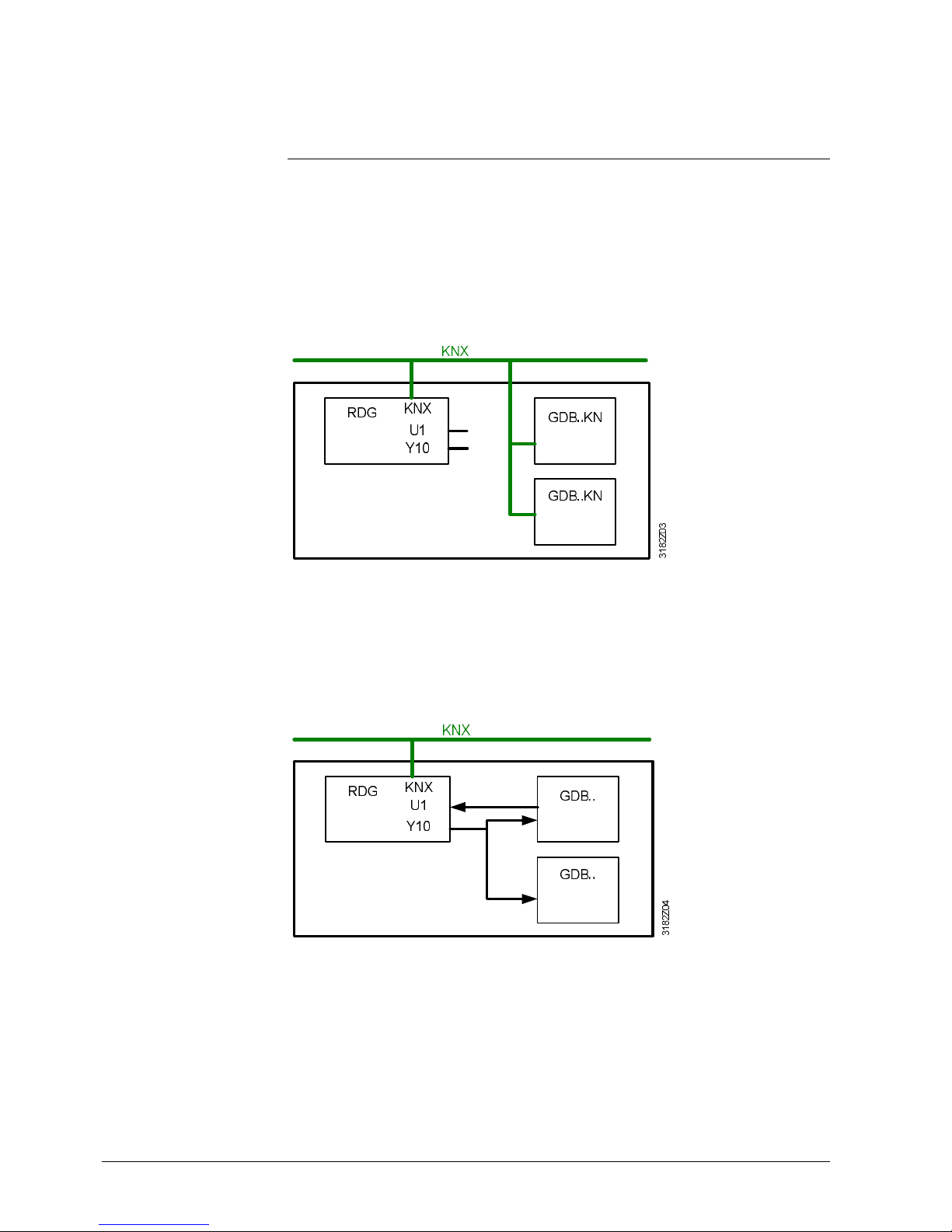
3.4.1 Applications with supply and extract air
Applications with supply and extract air can be realized in the following ways:
∂ Control signal from RDG.. and VAV air damper position (for primary air
optimization) are transmitted via KNX bus
∂ Communication settings (geographical zone, air distribution zone) of the RDG..
and the GDB..KN need to be set accordingly.
Reference see [18] and section 3.10.13.
∂ This application requires VAV compact controllers with KNX LTE-Mode
Master (supply air)
Slave (extract air)
∂ RDG.. output Y10 controls both VAV compact controllers for supply air and
extract air
∂ The current air damper position of one VAV compact controller is transmitted to
input U1 and via KNX for primary air optimization
∂ This application requires analog VAV compact controllers (noncommunicating)
Supply air
Extract air
Master/slave function
between the VAV
compact controllers for
supply and extract air
Parallel connection of
Y10 control signal and
air damper position
feedback via U1
Page 31
31 / 87
Siemens RDG400KN,RGD405KN Basic documentation CE1P3192en
Building Technologies 2017-02-17
3.5 Additional functions
The supply air temperature sent by the primary controller indicates whether cold or
warm air is supplied.
The controller determines the necessity to open or close the air damper according
to the supply air temperature, the room temperature setpoint and the current room
temperature.
If no supply air temperature is available via bus, air changeover is cooling per
default.
With "Single-duct" applications, changeover can also be accomplished via a local
multifunctional input X1-D1 (P38, P42).
Only one input source must be used, either local input X1-D1 or the KNX, and
parameter "Control sequence" must be set to automatic heating/cooling
changeover (P01 = 3).
For functionality of the local changeover input, see below (also refer to section 3.8).
With applications "Single-duct with heating/cooling coil", changeover information of
the heating/cooling coil can be received either via bus or the local multifunctional
input X1-D1 (P38, P42).
Only one input source must be used, either local input X1-D1 or the KNX, and
parameter "Control sequence" must be set to automatic heating/cooling
changeover (P01 = 3) (also refer to section 3.8).
In the absence of the required heating/cooling information from the bus (e.g. due to
problems with data communication, power failure, etc.), the thermostat operates in
the last valid operating mode (heating or cooling).
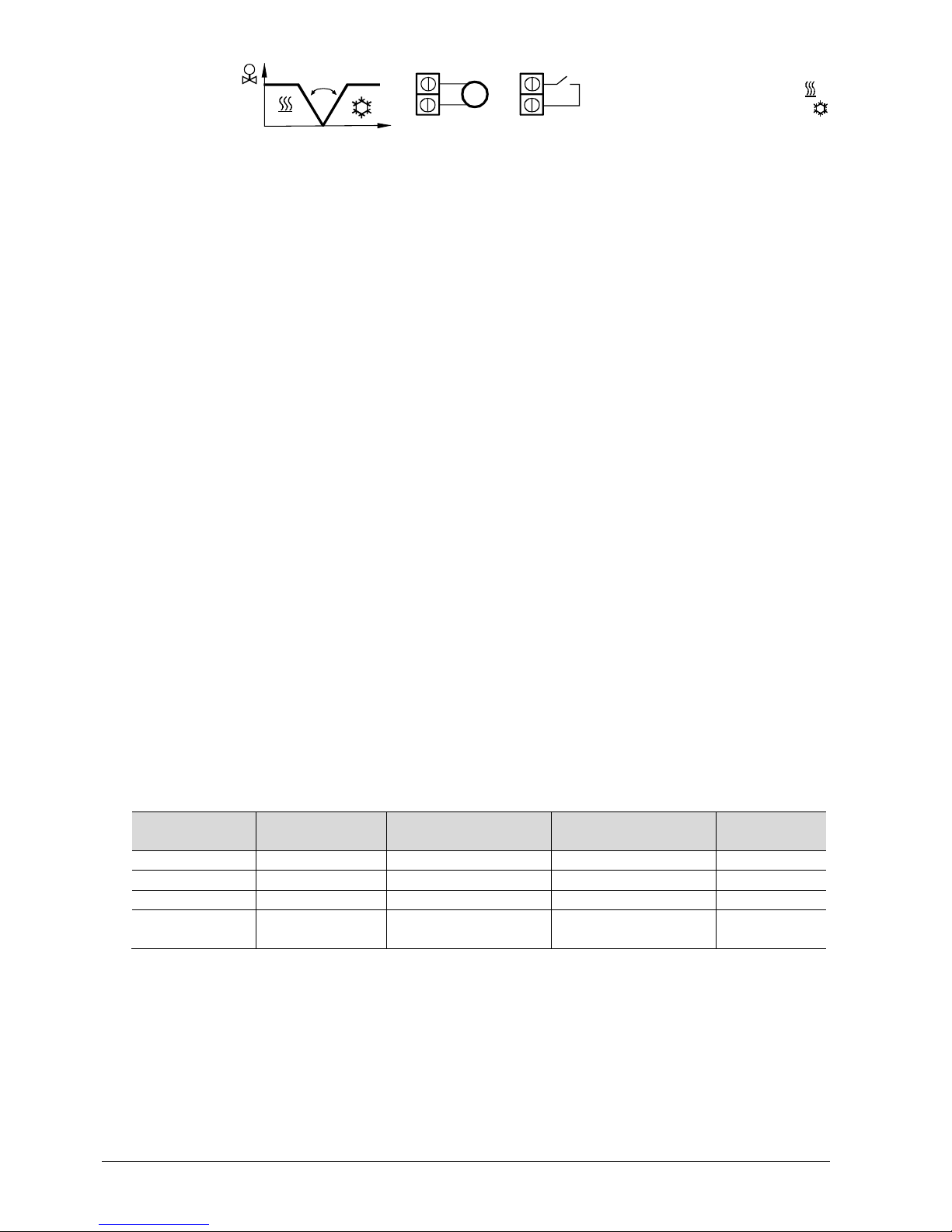
If a cable temperature sensor (QAH11.1 + ARG86.3) is connected to X1, and
P38 = 2, the water or supply air temperature acquired by the sensor is used to
change over from heating to cooling mode, or vice versa.
∂ When the water/air temperature is above 28 °C (adjustable via P37), the
thermostat changes over to heating mode. Heating mode is maintained until the
temperature falls below 16 °C (adjustable via P36)
∂ When the water/air temperature is below 16 °C (adjustable via P36), the
thermostat changes over to cooling mode. Cooling mode is maintained until the
temperature rises above 28°C (P37)
∂ If the water/air temperature is between the 2 changeover points immediately
after power-up (inside the hysteresis), the thermostat starts in the previous mode
The water/air temperature is acquired at 30-second intervals and the operating
state is updated accordingly.
P36
M
Tw[癈 ]
P37
3191D124
M Operating mode Cooling mode
Tw Water temperature Heating mode
The QAH11.1 cable temperature sensor for automatic heating/cooling changeover
can be replaced by an external switch for manual remote changeover.
Air heating/cooling
changeover
KNX
R
Supply air temperature
Water heating/cooling
changeover
KNX
R
Heating/cooling
changeover
Automatic heating/
cooling changeover via
changeover sensor
Changeover switch
Page 32
32 / 87
Siemens RDG400KN,RGD405KN Basic documentation CE1P3192en
Building Technologies 2017-02-17
3076Z 03
X2
M
T
X2
M
QAH11.1
T 癈
Contact open ⇓ heating mode
Contact closed ⇓ cooling mode
The sensor or switch can be connected to input X1 or D1 (switch only), depending
on the commissioning of the inputs (P38, P42) (also refer to section 3.8).
∂ Manual heating/cooling changeover means selection via changeover button on
the thermostat by repeatedly pushing the button until the required mode is
shown on the display (automatic changeover takes place via bus or an external
sensor/switch connected to X1 or D1)
∂ If manual heating/cooling changeover is commissioned (P01 = 2), heating/
cooling mode cannot be changed via bus/changeover sensor/switch; it maintains
the last mode as selected locally via the button
The thermostat acquires the room temperature via built-in sensor, external room
temperature sensor (QAA32) or external return air temperature sensor (QAH11.1)
connected to multifunctional input X1.
Input X1 must be commissioned accordingly (see section 3.8).
The floor temperature should be limited for 2 reasons: Comfort and protection of
the floor.
The floor temperature sensor connected to multifunctional input X1 acquires the
floor temperature. If the temperature exceeds the parameterized limit (P51), the
heating valve is fully closed until the floor temperature drops to a level 2 K below
the parameterized limit.
This function is factory-set to OFF (disabled).
Input X1 must be commissioned accordingly (P38 = 1) (see section 3.8).
Living rooms:
Up to 26 °C for long-time presence, up to 28 °C for short-time presence.
Bathrooms:
Up to 28 °C for long-time presence, up to 30 °C for short-time presence.
The table below shows the relation between parameter, temperature source and
temperature display:
Parameter P51
External temp.
sensor available
Source for display of
room temperature
Output control
according to …
Floor temp.
limit function
OFF No Built-in sensor Built-in sensor Not active
OFF Yes External temp. sensor External temp. sensor Not active
10...50 ˚C No Built-in sensor Built-in sensor Not active
10…50 ˚C Yes Built-in sensor
Built-in sensor + limit
by external sensor
Active
Dewpoint monitoring is essential to prevent condensation on the chilled ceiling.
It helps avoid associated damage to the building.
A dewpoint sensor with a potential-free contact is connected to multifunctional input
X1 or D1. If there is condensation, the cooling valve is fully closed until no more
condensation is detected, and the cooling output is disabled temporarily.
Manual heating/
cooling changeover
External/return air
temperature sensor
Floor temperature
limitation function
Recommended values
for P51
Dewpoint monitoring
Page 33
33 / 87
Siemens RDG400KN,RGD405KN Basic documentation CE1P3192en
Building Technologies 2017-02-17
The condensation symbol is displayed during temporary override and the fault
"Condensation in room" is sent via bus.
The input must be commissioned accordingly (P38, P42) (see section 3.8).
If the "Button lock" function is enabled via P14, the buttons will be locked or
unlocked by pressing the right button for 3 seconds.
If "Auto lock" is configured, the thermostat will automatically lock the buttons 10
seconds after the last adjustment.
3.6 Control sequences
3.6.1 Sequences overview (setting via P01)
The mode of the control sequence can be set via P01. Depending on the selected
application, it will have an impact either on the air or water sequence.
On all applications the changeover of the air sequence can be effected via the
supply air temperature sent by the primary controller.
The available sequences depend on the type of application:
Parameter
P01 = 0
P01 = 1
P01 = 2
P01 = 3
Sequence
T 癈
T 癈
T
癈
T 癈
T
c/o signal on
X1-D1
c/o signal
via bus
Supply air temp.
via bus
Available
for basic
application:
Heating Cooling
= heating
sequence for
electric heater/
radiator
Manually select
heating or cooling sequence
(using the
button on the
thermostat)
Automatic
heating/cooling
changeover via
external
water/air
temperature
sensor or
remote switch
Single-duct
1)1)
Single-duct and
electric heater
- - - -
1)
Single-duct and
radiator
- - - -
1)
Single-duct and
heating/cooling
coil
2)
2)
1)
1) Changeover air
2) Changeover water (heating/c ooling coil)
For the relation between setpoints and sequences, refer to section 3.6.9.
Application Parameter P01 influences the ...
Single-duct
Air sequence
Single-duct and
electric heater
--
KNX
R
Fault state
Fault information
Button lock
Note
Air sequence vs. water
sequence
Page 34
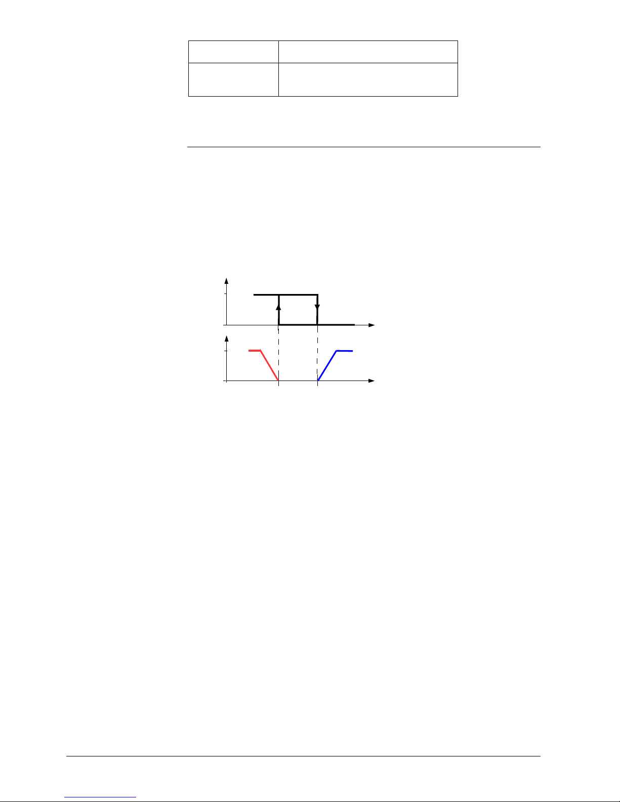
34 / 87
Siemens RDG400KN,RGD405KN Basic documentation CE1P3192en
Building Technologies 2017-02-17
Single-duct and
radiator
--
Single-duct and
heating/cooling
coil
Water sequence
3.6.2 Hysteresis: Behavior of heating and cooling
∂ The control sequences heating and cooling depend on the heating and cooling
setpoints and the room temperature
∂ The thermostat remains in the heating sequence as long as the room
temperature does not reach the cooling setpoint
∂ The thermostat remains in the cooling sequence as long as the room
temperature does not reach the heating setpoint
The value of the output and the sequence as a function of the room temperature is
shown in the following diagram in the case of a heating and cooling system:
0
TR
Wheat Wcool
100%
0 = Cool
1 = Heat
3171D0 1
Wheat = current setpoint heating
Wcool = current s etpoint c ooling
Page 35
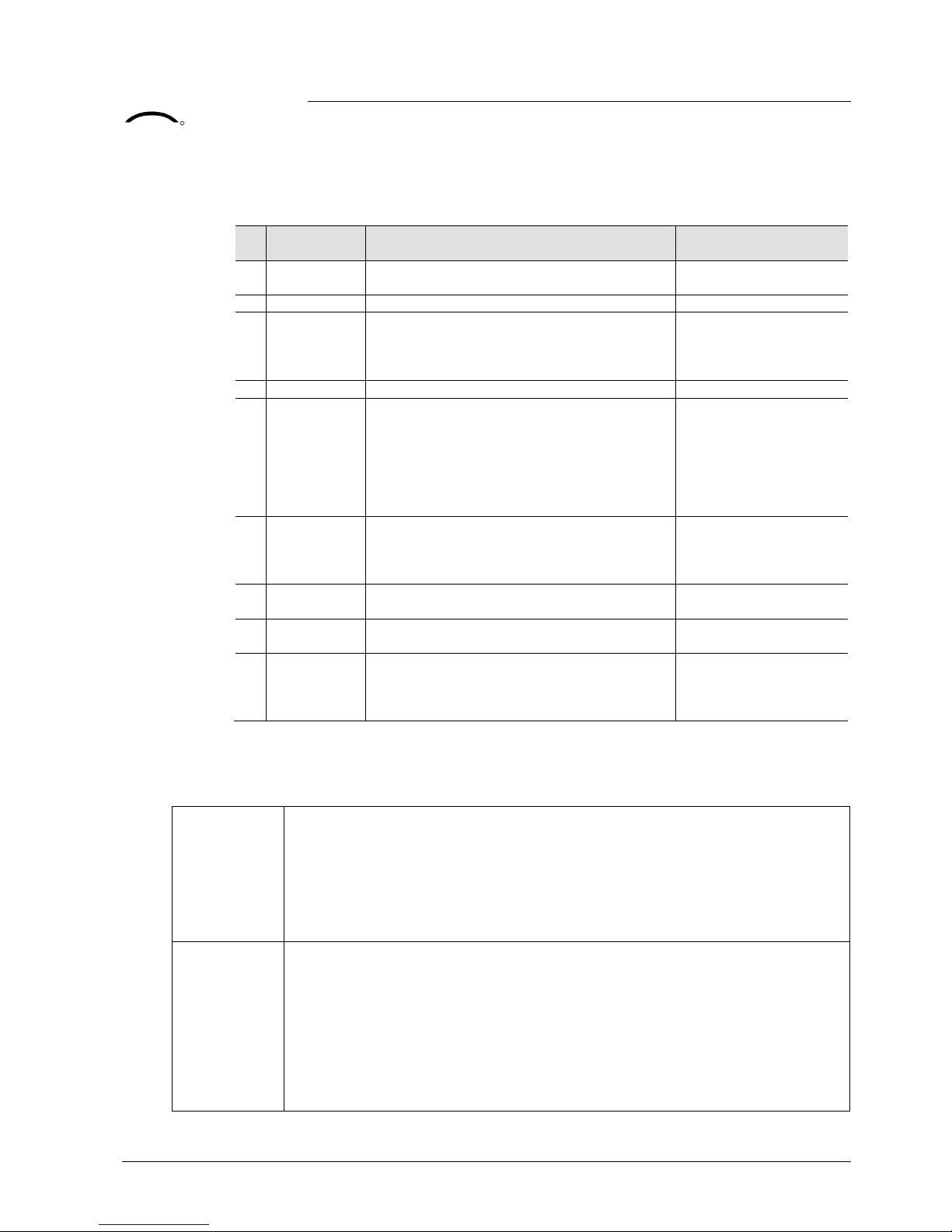
35 / 87
Siemens RDG400KN,RGD405KN Basic documentation CE1P3192en
Building Technologies 2017-02-17
3.6.3 Application mode
The behavior of the thermostat can be influenced by a building automation and
control system (BACS) via bus using the Application mode command. With this
signal, cooling and/or heating activity can be enabled or disabled. Application mode
is supported in LTE- and S-Mode. The RDG..KNX room thermostats support the
following commands:
#
Application
mode
Description
Control sequence
enabled
0 Auto Thermostat automatically changes between
heating and cooling
Heating and/or cooling
1 Heat Thermostat is only allowed to heat Heating only
2 Morning
warm-up
If
Morning warm
-
up
is received, the room
should be heated up as fast as possible (if
necessary). The thermostat only allows
heating
Heating only
3 Cool Thermostat is only allowed to provide cooling Cooling only
4 Night purge
If
N
ight purge
is received, the room should
be aired with cool outside air if necessary.
The thermostat opens the air damper and
does not heat/cool with the coils or the
electric heater.
Function will be ended by any operation on
the thermostat
Open air damper fully
if night purge condition
is valid
1)
5 Pre-cool
If
Pre-cool
is received, the room should be
cooled down as fast as possible (if
necessary). The thermostat only allows
cooling
Cooling only
6 Off Thermostat is not controlling the outputs,
which means all outputs go to off or 0%
Neither heating nor
cooling
8 Emergency
heat
The thermostat should heat as much as
possible. The thermostat only allows heating
Heating only
9 Fan only All control outputs are set to 0% and the air
damper is fully opened.
Function will be ended by any operation on
the thermostat
Open air damper fully
With all other commands, the thermostat behaves like in Auto mode, i.e. heating or
cooling according to demand.
1) Conditions for the "Night purge" function:
RDG400KN The function is activated when …
A: No supply air temperature via KNX is available:
Current room temperature > Comfort setpoint cooling
B: The supply air temperature via KNX is available (or air changeover is made by the
supply air temperature via KNX):
Current room temperature > supply air temperature and current room
temperature > Comfort setpoint cooling
RDG405KN Function is activated when:
A: No supply air temperature is not available:
Current room temperature > Calculate Comfort heating setpoint plus 1K
B: Supply air temperature is available
Current room temperature > Calculate Comfort heating setpoint plus 1K and
the supply air temperature is plus 3K < Current room temperature.
Function is deactivated when:
The current room temperature < Calculate Comfort heating setpoin or
The supply air temperature plus 2K > Current room temperature
KNX
R
Application mode
Page 36
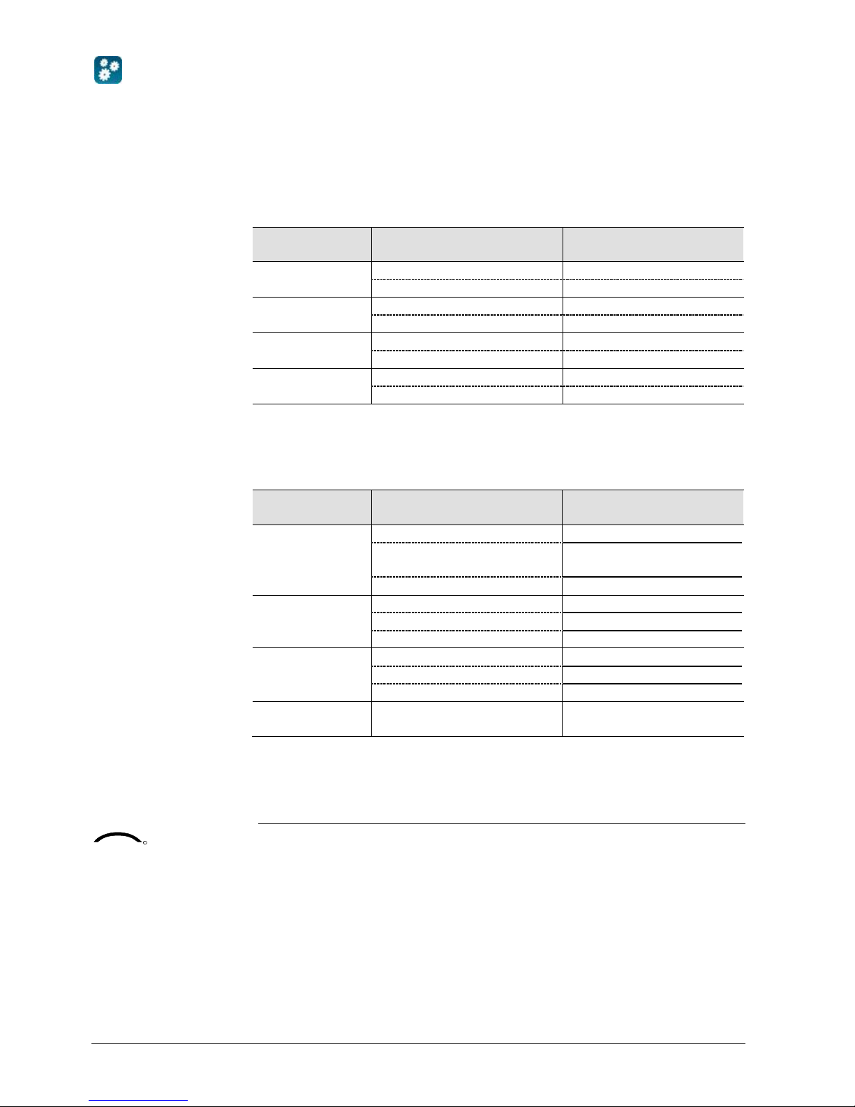
36 / 87
Siemens RDG400KN,RGD405KN Basic documentation CE1P3192en
Building Technologies 2017-02-17
The state (heating or cooling) of the thermostat can be monitored with the ACS tool
(diagnostic value "Control sequence"). The last active mode is displayed when the
thermostat is in the dead zone or temperature control is disabled.
On single-duct applications, the control sequence state is determined by the
application mode (see section 3.6.2) and by the state of the heating/cooling
changeover signal (via local sensor or bus), or fixed according to the selected
control sequence (P01 = heating (0)/cooling (1)).
Application
mode (via bus)
State changeover/continuous heating or cooling
Control sequence state
(ACS diagnostic value)
Auto (0)
Heating Heating
Cooling Cooling
Heat (1), (2), (8) Heating Heating
Cooling
Heating
Cool (3), (5)
Heating
Cooling
Cooling Cooling
Night purge (4),
Fan only (9)
Heating Heating
Cooling Cooling
On applications "Single-duct with electric heater/radiator/heating/cooling coil", the
control sequence state depends on the application mode and the heating/cooling
demand.
Application
mode (via bus)
Heating/cooling demand Control sequence state
(ACS diagnostic value)
Auto (0)
Heating Heating
No demand Heating/cooling depending
on last active sequence
Cooling Cooling
Heat (1), (2), (8)
Heating Heating
No demand
Heating
Cooling
Heating
Cool (3), (5)
Heating
Cooling
No demand
Cooling
Cooling Cooling
Night purge (4),
Fan only (9)
No temperature control active Heating/cooling depending
on last active sequence
3.6.4 Minimum and maximum air volume
The factory setting for minimum and maximum air volume is 0/100% respectively.
These values can be changed via P63/P64. Alternatively, Vmin and Vmax can be
set directly on the VAV compact controller (G..B181.E/KN).
If Vmin is greater than 0, a minimum air flow Vmin is ensured in both Comfort and
Economy mode.
In Protection mode (or Economy with setpoint = OFF), Vmin is fixed to 0.
Comfort or Economy mode Protection mode: Vmin always = 0
ACS
Heating OR cooling
Heating AND cooling
KNX
R
Page 37
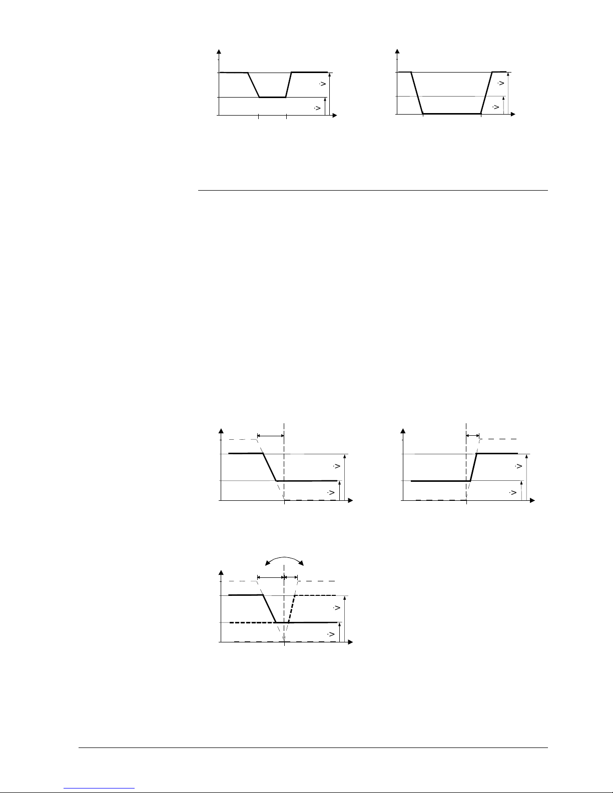
37 / 87
Siemens RDG400KN,RGD405KN Basic documentation CE1P3192en
Building Technologies 2017-02-17
max
min
Y
0%
100%
TR [癈]
YV
CH
Vmin
Vmax
SpH
Comf/E co
SpC
Comf/ Eco
max
min
Y
0%
100%
TR [癈]
YV
C
H
Vmin
Vmax
SpH
Prot
SpC
Prot
3.6.5 Single-duct applications
On single-duct applications, the thermostat controls an actuator (air damper, VAV
system, valve, etc.) …
– in heating/cooling mode with changeover (automatically or manually),
– in heating only mode, or
– cooling only mode.
Cooling only is factory-set (P01 = 1).
The output signal for the air flow can be limited to a minimum and maximum value
if required (see section 3.4.1).
Modulating control: 3-position or DC 0…10 V, KNX LTE-Mode
The diagrams below show the control sequence for modulating PI control.
Heating only (P01 = 0) Cooling only (P01 = 1)
max
min
XpH
Y
0%
100%
TR [癈 ]
W
H
Vmin
Vmax
max
min
Y
0%
100%
TR [癈 ]
XpC
W
C
Vmin
Vmax
Changeover (P01 = 2, 3)
max
min
Changeover
XpH
Y
0%
100%
TR [癈 ]
XpC
W
C
H
Vmin
Vmax
T[°C] Room temperature XpH Pr oportional band "Heating"
w Room temperature setpoint XpC Pr oportional band "Cooling"
Y Control command Actuator Vmin Minimum limitation for output
Vmax Maximum limitation f or output
Page 38

38 / 87
Siemens RDG400KN,RGD405KN Basic documentation CE1P3192en
Building Technologies 2017-02-17
∂ The diagrams only show the PI controller’s proportional part
∂ Switching between heating and cooling depends on the setpoints and the room
temperature (see section 3.6.2)
Setting the sequence and the control outputs
Refer to sections 0, 3.6.1 and 3.7.
3.6.6 Single-duct applications with electric heater
General rule: In case of insufficient air flow, the thermostat cannot protect the
electric heater against overtemperature. For this reason, the heater must be
equipped with a separate safety device (thermal cutout).
On single-duct applications with electric heater, the thermostat controls a valve
plus an electric heater. P01 is not available.
The output signal for the air flow can be limited to a minimum and maximum value
if required using P63 and P64. On applications "Single-duct with electric heater",
the minimum value of P63 is overridden, so that the air flow never drops below
10% while the electric heater is in operation.
The air flow starts to rise depending on the acquired room temperature, the current
supply air temperature (if available) and the setpoint.
The electric heater receives an On command when the acquired room temperature
drops below the setpoint (= setpoint for electric heater).
Remote enabling/disabling of the electric heater is possible via input X1 or D1 for
tariff regulations, energy savings, etc.
Input X1 or D1 must be commissioned accordingly (P38, P42) (see section 3.8).
The electric heater can also be enabled/disabled via bus.
If input "Enable electric heater" is used via bus, the function must not be assigned
to a local input X1 or D1.
On start-up of the controller and if the primary controller sends the information that
the primary fan is off, the thermostat disables the electric heater (see section
3.10.9).
To avoid overheating of an electric heater when switched off, the air flow signal of
Vmin must be maintained for a preset "Fan overrun time" (P54, factory setting
60 seconds).
In connection with a Synco primary controller it will be ensured that the primary fan
keeps running during the fan overrun time (also refer to section 3.10.10).
Notes
Caution
Electric heating,
active in cooling mode
Digital input "Enable
electric heater"
KNX
R
Enable electric heater
Note
Fan overrun time
Page 39
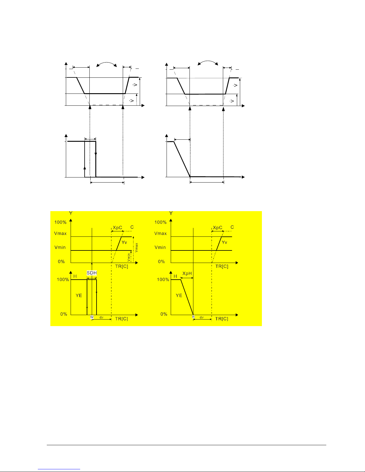
39 / 87
Siemens RDG400KN,RGD405KN Basic documentation CE1P3192en
Building Technologies 2017-02-17
Sequences
On/Off electric heater RDG400KN Modulating electric heater RDG400KN
Y
YE
TR [癈 ]
dz
max
min
Y
0%
100%
TR [癈 ]
XpC
YV
CH
Vmin
Vmax
XpH
ON
OFF
W
SDH
Change-over air
Y
0%
100%
YE
TR [癈 ]
XpH
W
dz
max
min
Y
0%
100%
TR [癈 ]
XpC
YV
C
H
Vmin
Vmax
XpH
Change-over air
On/Off electric heater RDG405KN Modulating electric heater RDG405KN
1-stage heating: Changeover air is recognized as cooling or neutral
Page 40
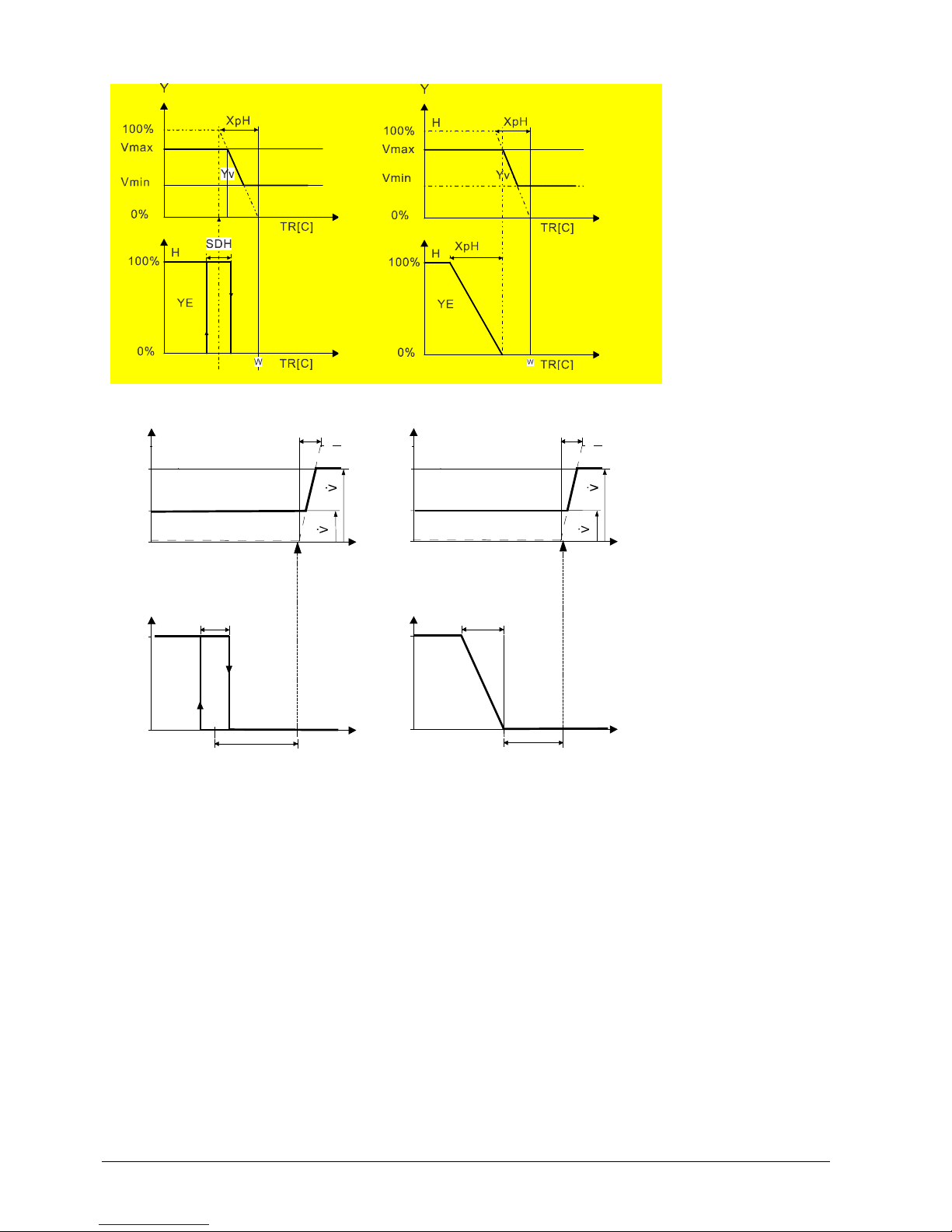
40 / 87
Siemens RDG400KN,RGD405KN Basic documentation CE1P3192en
Building Technologies 2017-02-17
2-stage heating: Changeover air is recognized as heating
Without a valid bus signal for changeover air, the air volume is only increased for cooling:
Y
YE
TR [癈 ]
dz
max
min
Y
0%
100%
TR [癈 ]
XpC
YV
C
Vmin
Vmax
ON
OFF
W
SDH
Y
0%
100%
YE
TR [癈 ]
XpH
W
dz
max
min
Y
0%
100%
TR [癈 ]
XpC
YV
C
Vmin
Vmax
Y Output signal
TR Room temperature
W Effective setpoint Comfort
H Heating sequence
C Cooling sequence
YV Volume flow rate
YE Electric heater
XpH Proportional band heating
XpC Proportional band cooling
Vmin Minimum volume output
Vmax Maximum volume output
SDH Switching differential
heating (P30)
∂ The diagrams only show the PI thermostat’s proportional part
∂ Switching between heating and cooling depends on the setpoints and the room
temperature (see section 3.6.2)
Setting the sequence and the control outputs
Refer to sections 0, 3.6.1 and 3.7.
Notes
Page 41
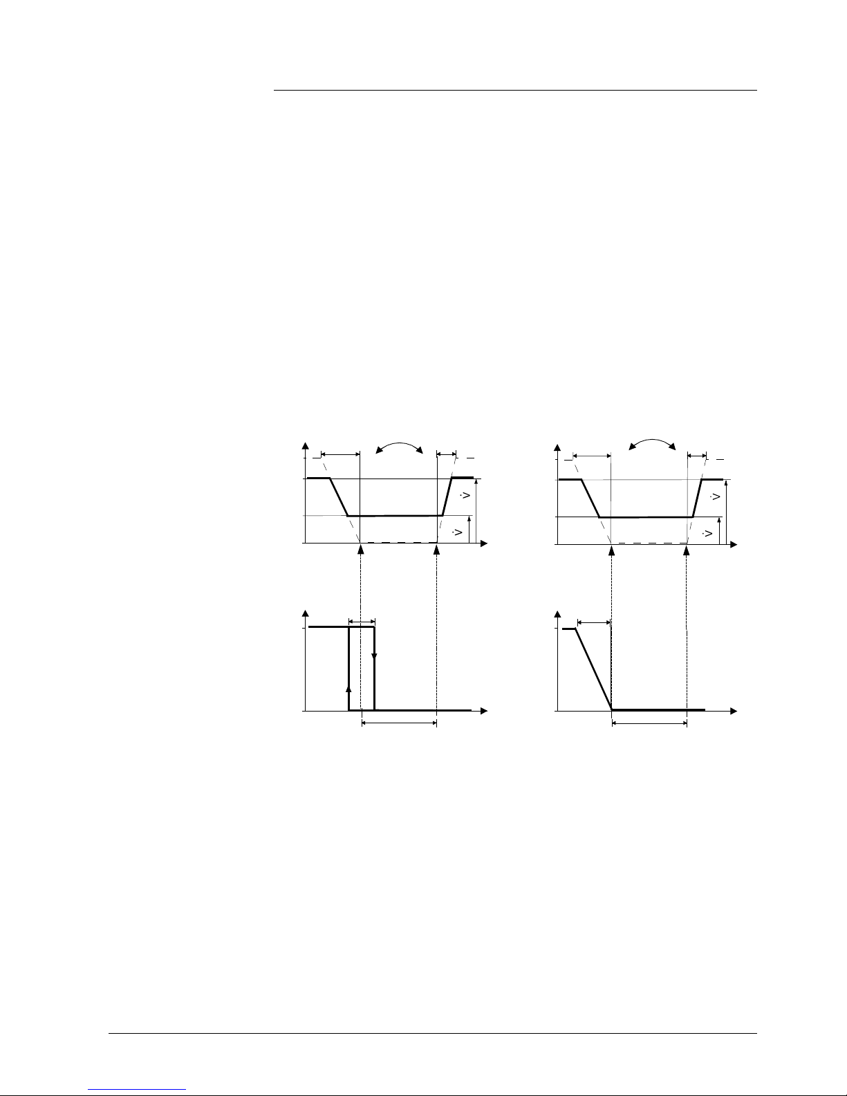
41 / 87
Siemens RDG400KN,RGD405KN Basic documentation CE1P3192en
Building Technologies 2017-02-17
3.6.7 Single-duct applications with radiator or floor heating
On single-duct applications with radiator or floor heating, the thermostat controls an
air damper or a VAV compact controller plus a valve actuator. P01 is not available.
The output signal for the air flow can be limited to a minimum and maximum value
if required (see section 3.4.1).
The air flow starts to rise depending on the acquired room temperature, the current
supply air temperature (if available) and the setpoint.
The radiator receives an On command when the acquired room temperature drops
below the setpoint (= setpoint for radiator).
"Setpoint for radiator" is limited by the parameter "Maximum heating setpoint"
(P10).
The radiator sequence can also be used for floor heating.
The "Floor temperature limitation" function is described on page 32.
2-position radiator/floor heating Modulating radiator/floor heating
Y
YR
TR [癈 ]
dz
max
min
Y
0%
100%
TR [癈 ]
XpC
YV
C
H
Vmin
Vmax
XpH
ON
OFF
W
SDR
Changeover air
Y
0%
100%
YR
TR [癈 ]
XpR
W
dz
max
min
Y
0%
100%
TR [癈 ]
XpC
YV
C
H
Vmin
Vmax
XpH
Changeover air
Y Output signal
TR Room temperature
W Effective setpoint Comfort
H Heating sequenc e
C Cooling sequence
YV Volume flow rate
YR Radiator/f loor heat ing
XpH Proportional band heating
XpC Pr oportional band c ooling
Vmin Minimum volume out put
Vmax Maximum volume output
SDR Switching differential radiator
Radiator, active in
cooling mode
Note
Floor heating
Sequences
Page 42

42 / 87
Siemens RDG400KN,RGD405KN Basic documentation CE1P3192en
Building Technologies 2017-02-17
Without a valid bus signal for changeover air, the air volume is only increased for
cooling:
2-position radiator/floor heating Modulating radiator/floor heating
Y
YR
TR [癈 ]
dz
max
min
Y
0%
100%
TR [癈 ]
XpC
YV
C
Vmin
Vmax
ON
OFF
W
SDH
Y
0%
100%
YR
TR [癈 ]
XpH
W
dz
max
min
Y
0%
100%
TR [癈 ]
XpC
YV
C
Vmin
Vmax
Y Output signal
TR Room temperature
W Effective setpoint Comfort
H Heating sequenc e
C Cooling sequence
YV Volume flow rate
YR Radiator/f loor heat ing
XpH Proportional band heating
XpC Pr oportional band c ooling
Vmin Minimum volume out put
Vmax Maximum volume output
SDH Switching differential heating
∂ The diagrams only show the PI controller's proportional part
∂ Switching between heating and cooling depends on the setpoints and the room
temperature (see section 3.6.2)
Setting the sequence and the control outputs
Refer to sections 0, 3.6.1 and 3.7.
Notes
Page 43
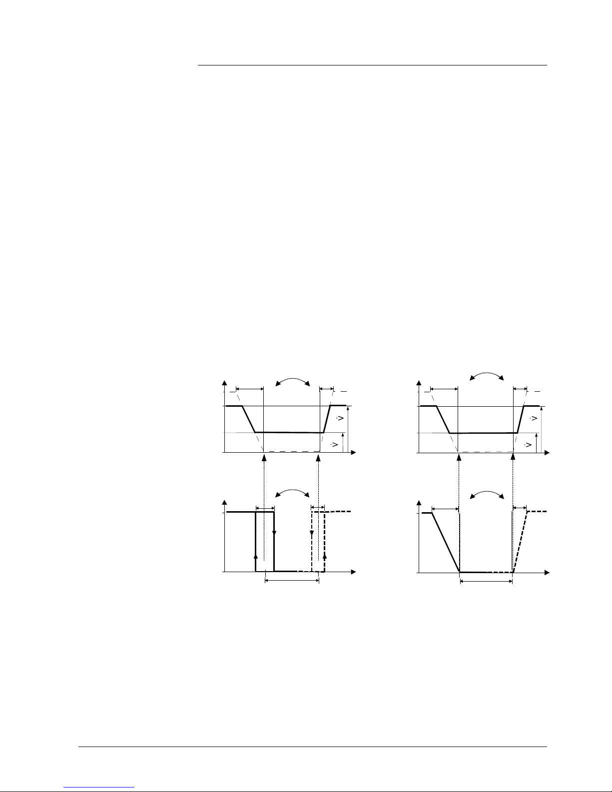
43 / 87
Siemens RDG400KN,RGD405KN Basic documentation CE1P3192en
Building Technologies 2017-02-17
3.6.8 Single-duct applications with heating/cooling coil
On single-duct applications with heating/cooling coil, the thermostat controls an
actuator (air damper, VAV system, etc.) plus a heating/cooling water coil.
The output signal for the air flow can be limited to a minimum and maximum value
if required (see section 3.4.1).
The thermostat controls the reheating/cooling water valve either in heating/cooling
mode with changeover (automatically or manually), heating only, or cooling only.
Cooling only is factory-set (P01 = 01).
The air flow starts to rise depending on the acquired room temperature, the current
supply air temperature (if available) and the setpoint.
If the room temperature is above the setpoint for cooling (w), the valve receives an
Open command and the air flow signal starts to rise to maintain the room
temperature setpoint.
If the room temperature drops below the setpoint for heating (w), the valve receives
an Open command.
The diagrams below show the control sequence for modulating PI control in
Comfort mode.
2-position heating/cooling coil Modulating heating/cooling coil
Y
YHC
TR [癈 ]
SDC
C
H
dz
max
min
Y
0%
100%
TR [癈 ]
XpC
YV
C
H
Vmin
Vmax
XpH
Changeover water
YHC
ON
OFF
w
SDH
Changeover air
(w)
Y
0%
100%
YHC
TR [癈 ]
XpH
w
XpC
YHC
C
H
dz
max
min
Y
0%
100%
TR [癈 ]
XpC
YV
C
H
Vmin
Vmax
XpH
Changeover water
Changeover air
(w)
Y Output signal
TR Room temperature
w Comfort setpoint when heat ing sequence active
(w) Comfort setpoint when cooling sequence active
H Heating sequenc e
C Cooling sequence
YV Volume flow rate
XpH Proportional band heating
XpC Pr oportional band c ooling
Vmin Minimum volume out put
Vmax Maximum volume output
SDH Switching differential heating
Water coil valve in
cooling mode
Water coil valve in
heating mode
Control sequence
Page 44

44 / 87
Siemens RDG400KN,RGD405KN Basic documentation CE1P3192en
Building Technologies 2017-02-17
Without a valid bus signal for changeover air, the air volume is only increased for
cooling.
2-position heating/cooling coil Modulating heating/cooling coil
Y
YHC
TR [癈 ]
SDC
C
H
dz
max
min
Y
0%
100%
TR [癈 ]
XpC
YV
C
Vmin
Vmax
Changeover water
ON
OFF
w
SDH
YHC
(w)
Y
0%
100%
YHC
TR [癈 ]
XpH
w
XpC
YHC
C
H
dz
max
min
Y
0%
100%
TR [癈 ]
XpC
YV
C
Vmin
Vmax
Changeover water
(w)
Y Output signal
TR Room temperature
w Comfort setpoint when heat ing sequence active
(w) Comfort setpoint when cooling sequence active
H Heating sequenc e
C Cooling sequence
YV Volume flow rate
XpH Proportional band heating
XpC Pr oportional band c ooling
Vmin Minimum volume out put
Vmax Maximum volume output
SDH Switching differential heating
∂ The diagrams only show the PI controller's proportional part
∂ Switching between heating and cooling depends on the setpoints and the room
temperature (see section 3.6.2)
Setting the sequence and the control outputs
Refer to sections 0, 3.6.1 and 3.7.
Notes
Page 45

45 / 87
Siemens RDG400KN,RGD405KN Basic documentation CE1P3192en
Building Technologies 2017-02-17
3.6.9 Setpoints and sequences
Comfort setpoint (w) is in the currently active heating or cooling sequence.
∂ If the supply air temperature is available (via KNX), the air
flow may also increase when the room temperature is
below the heating setpoint
∂ If no supply air temperature is available, the sequence for
air flow control is cooling only
The setpoints for Economy and Protection mode are below the Comfort setpoints
(heating) and above the Comfort setpoints (cooling).
They can be set via P11, P12 (Economy) and P65, P66 (Protection).
w
3181D127
T[癈]
w
HeatProt
w
CoolProt
w
HeatEco
w
CoolEco
Comfort mode
Economy/Protection mode
Application
Heating Cooling Heating Cooling
Single-duct 1)
Single-duct with
electric heater/
radiator/floor
heating
Single-duct with
heating/cooling
coil
Heating and cooling Heating and cooling
SW < 1.24/
device index < C
only: Single-duct
with electric
heater/radiator/
floor heating
W = setpoint in Comfort mode
W
HeatEco/Prot
= setpoint heating in Ec onomy or P rotection mode
W
CoolEco/Prot
= setpoint cooling in Ec onomy or Protection mode
Y = air/water sequence
T = room temperature
The dead zone can be adjusted via P33.
1) Single-duct: A dead zone can be set also. In this case, the diagram is the same as for single-duct
with electric heater
Changeover air
Economy, Protection
Y
T
W
H
eatEco/P
rot
Y
T
W
Y
T
W
CoolEco/P
rot
Y
T
W
H
eatEco/P
rot
Y
T
W
Y
T
W
Y
T
W
CoolEco/P
rot
Y
T
W
H
eatEco/P
rot
Y
T
W
Y
T
W
Y
T
W
CoolEco/P
rot
Y
T
W
H
eatEco/P
rot
Y
T
W
Y
T
W
Page 46

46 / 87
Siemens RDG400KN,RGD405KN Basic documentation CE1P3192en
Building Technologies 2017-02-17
3.6.10 Applications with external AQR sensor or QMX room
operator unit (RDG405KN)
The equipment combination is for use in commercial buildings, offices, schools,
museums, shops, etc.
AQR/QMX sensor
Advantages of equipment combination LTE-Mode S-Mode
a)
Sensor can be installed in the optimal place for
temperature
acquisition
b) Unauthorized people cannot change settings on sensors installed in the room
c) The HVAC equipment and measurement point (T, CO2) are far apart (e.g. in
large spaces). Installing the thermostat near the equipment and the sensor on
the measurement point reduces wiring costs and increases control accuracy
d) Several RDG.. room thermostats can operate with one room temperature
and/or CO2 value (in large spaces)
x
e) AQR/QMX sensor is more appropriate for interior design
With sensor AQR25.. or QMX3..0
The AQR25.. and QMX3.P.. sensors can deliver room temperature and CO2 values
to the RDG405KN.
The RDG405KN and the sensors use LTE-Mode (KNX) communication. To
exchange information (room temperature or CO2 values), both devices must have
the same geographical zone, apartment and room (A.R.1, where "A" is the value of
P82 and "R" is the value of P83 of the RDG405KN). This equipment combination
works on a 1-to-1 basis. Values cannot be delivered from the sensor to several
RDG405KN room thermostats.
For applications in S-Mode, the objects for room temperature of the RDG405KN
must be set to Receive in ETS. The thermostat then works with the values
acquired by the sensor. Default setting Transmit indicates that the RDG405KN
provides the local room temperature via bus. One sensor can deliver data to
several thermostats.
For commissioning with ACS V10 software: Set the same geographical zone on the
RDG.. and the Siemens KNX sensor AQR..
∂ In the corresponding geographical/time switch zone, the RDG405KN is
shown under "Slaves"
∂ The IAQ KNX sensor (e.g. AQR2570) must be assigned as "Networked
devices" of the RDG405KN
The linked image cann ot be display ed. The file may hav e been moved, r enamed, or deleted. Verify that the link p oints to the cor rect file and location.
Note
Page 47

47 / 87
Siemens RDG400KN,RGD405KN Basic documentation CE1P3192en
Building Technologies 2017-02-17
3.7 Control outputs
3.7.1 Overview
Different control output signals are available depending on the configuration of the
thermostat via DIP switches 4 and 5, and P46 and P47.
Control output
Product No.
Modulating
DC 0…10 V
2-position
On/Off
2-position
PWM
Modulating
3-position
Modulating
KNX
RDG400KN
RDG405KN
Y10
Y1
1)Y11)
Y1/Y2
1)
(1 x / )
KNX LTE-Mode
1) Either On/Off, PWM or 3-position (triac)
For configuration of the control outputs, refer to section 3.7.4.
3.7.2 Control output for air flow
The demand calculated by PI control from the current room temperature and the
setpoint is delivered to the damper actuator as a modulating DC 0...10 V signal via
output Y10.
A 3-position control output for an air damper has 2 control signals, one for the
Open command and one for the Close command. The thermostat features an
internal stroke model to calculate the position of the actuator. Therefore, the
running time from the fully closed to the fully open position must be adjusted via
P44 (from 20 to 300 seconds; factory setting is 150 seconds).
A VAV compact controller receives its control signal via KNX bus.
For communication settings (geographical zone, air distribution zone), refer to
sections 3.10.3 and 3.10.13.
On single-duct applications, a closing synchronization is effected to readjust the
internal stroke model to the real position of the actuator.
1. When the thermostat starts up, a closing signal (actuator running time + 150%
= 2.5 x running time) is delivered to ensure the actuator will be fully closed
and synchronized with the control algorithm.
2. Each time the thermostat calculates the fully closed position, the actuator’s
running time is extended + 150% to ensure the corrrect position of the
actuator.
3. When the actuator reaches the position calculated by the thermostat, a
waiting time of 30 seconds is observ ed to stabilize the outputs.
"Opening" synchronization is available for valve outputs only.
DC 0...10 V
control signal
3-position
control signal
Control signal
(KNX LTE mode only)
Synchronization
Note
Page 48
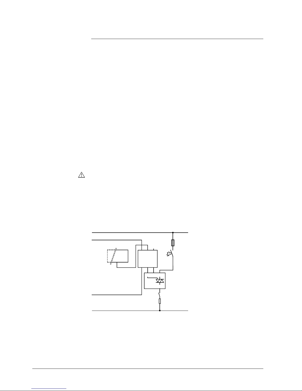
48 / 87
Siemens RDG400KN,RGD405KN Basic documentation CE1P3192en
Building Technologies 2017-02-17
3.7.3 Control output for electric heater, radiator and heating/
cooling coil
The valve receives an Open/On command via control output Y1 when …
1. the acquired room temperature is below the setpoint (heating mode) or above
the setpoint (cooling mode),
2. the control outputs have been inactive for more than the "Minimum output off-
time" (factory setting 1 minute).
Off command for valve output when …
1. the acquired room temperature is above the setpoint (heating mode) or below
the setpoint (cooling mode),
2. the valve has been active for more than the "Minimum output on-time" (factory
setting 1 minute).
The electric heater receives an On command via output Y1 when …
1. the acquired room temperature is below the "Setpoint for electric heater",
2. the electric heater has been switched off for at least 1 minute.
The Off command for the electric heater is output when …
1. the acquired room temperature is above the setpoint (electric heater),
2. the electric heater has been switched on for at least 1 minute.
A safety thermostat (to prevent overheating) must be provided externally.
∂ The demand calculated by PI control from the current room temperature and the
setpoint are delivered via Y10 as a modulating DC 0...10 V signal
∂ The signal converter (SEM61.4) converts the DC 0...10 V signal to AC 24 V
PDM pulses for the current valve
∂ The current valve (SEA45.1) supplies the electric heater with AC 50…660 V
pulsed current
YE
DC 0 ... 10 V
Y1G
L
N
Y1 L
Q
5.7 kW
max.
N1
U1
FF
F...
Y1
K...
G0
G
G
318 1D21
G
G0
Y
PWM
AC 24 V
N1 RDG400KN
U1 Signal converter SEM61.4 (see Data S heet N5102)
Y1 Current valve SEA45.1 (see Data Sheet N4937)
K… Safety loop (e.g. safety thermostat and high-temperature cutout)
FF Very fast-acting fuse
F… Overcurrent trip
On/Off control signal
(valve, 2-position)
Electric heater control
signal
(2-position)
Caution
DC 0...10 V
for electric heaters
Page 49

49 / 87
Siemens RDG400KN,RGD405KN Basic documentation CE1P3192en
Building Technologies 2017-02-17
Output Y1 delivers the Open command, and Y2 the Close command to the 3position actuator.
The factory setting for the actuator’s running time is 150 seconds. It can be
adjusted via P44 (Y1 and Y2).
The parameter is only visible if 3-position is selected via DIP switch 5 or the
commissioning tool.
1. When the thermostat is powered up, a Close command for the actuator’s
running time + 150% is delivered to ensure that the actuator fully closes and
synchronizes to the control algorithm.
2. When the thermostat calculates the positions "Fully closed" or "Fully open",
the actuator’s running time is extended + 150% to ensure the correct actuator
position is synchronized with the control algorithm.
3. After the actuator reaches the position calculated by the thermostat, a waiting
time of 30 seconds is applied to stabilize the outputs.
The demand calculated by PI control from the current room temperature and the
setpoint is delivered via Y1 to the valve actuator as a PWM signal (pulse width
modulation) for thermal actuators. The output is switched on for a period proportional to the heating/cooling demand and then switched off for the rest of the PWM
interval.
The interval is 150 seconds (factory setting). It can be adjusted via P44 (Y1). The
parameter is only visible if 2-position is selected via DIP switch 5 or the
commissioning tool.
For PWM, the integral time (P35) must be set to 0!
For thermal valve actuators, set the running time to 240 seconds.
∂ Never apply PWM to an electromotoric actuator
∂ It is not possible to ensure exact parallel running of more than 2 thermal valve
actuators. If several VAV systems are driven by the same thermostat,
preference should be given to electromotoric actuators with On/Off or 3-position
control
For electric heaters, set the running time to 90 seconds.
To avoid burn-off of mechanical contacts by frequent switching, use a current valve
(e.g. SEA45.1) in place of a relay or contactor.
For PWM, the integral time (P35) must be set to 0.
3-position control
signal
Synchronization
PWM control
Note
PWM for thermal
valve actuators
Notes
PWM for electric heaters
Note!
Page 50
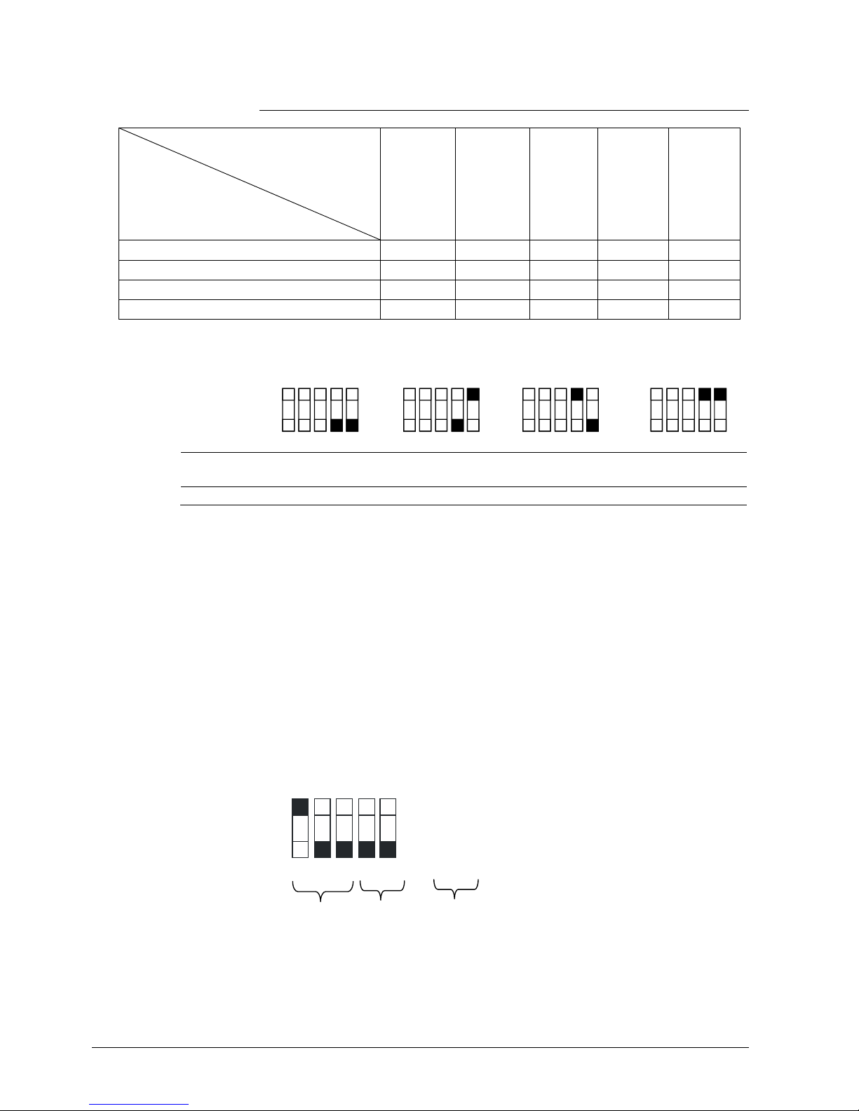
50 / 87
Siemens RDG400KN,RGD405KN Basic documentation CE1P3192en
Building Technologies 2017-02-17
3.7.4 Control outputs configuration (setting via DIP
switches 4 and 5 or tool, and P46…P47)
Control outputs
Application
On/Off
(2-position)
Modulating
PWM
(2-position)
Modulating
3-position
Modulating
DC 0…10 V
Modulating
KNX
Single-duct
Single-duct and electric heater
Single-duct and radiator/floor heating
Single-duct heating/cooling coil
The function of the control outputs is set via DIP switches 4 and 5:
ON
OFF
12345
ON
OFF
123 45
ON
OFF
123 45
ON
OFF
12345
3181D101
DIP 4: Y10 = DC 0…10 V DC 0…10 V DC 10…0 V
(inverted)
DC 10…0 V
(inverted)
DIP 5: Y1/Y2 = 2-position 3-position 2-position 3-position
Y1-Y2:
∂ If 2-position is selected, the factory setting is On/Off.
If PWM is required (pulse width modulation), P46 must be set to 2 = PWM
P47:
∂ 0 = VAV box: DC 0…10 V control signal or KNX LTE-Mode
∂ 1 = VAV box: 3-position control signal
All DIP switches must be set to OFF if the application is commissioned via tool. In
this case, the control outputs must be set via the ACS tool.
For details concerning connection of peripheral devices and setting of the DIP
switches, refer to the Mounting Instructions M3192 [3].
Single-duct with 3-position damper actuator:
ON
OFF
12345
P47 = 1
Application Y1/Y2 =
3-position
Control output
VAV = 3-position
Notes
Example
Page 51

51 / 87
Siemens RDG400KN,RGD405KN Basic documentation CE1P3192en
Building Technologies 2017-02-17
3.8 Multifunctional input, digital input
The thermostat has 2 multifunctional inputs X1 and a digital input D1.
An NTC type sensor like the QAH11.1 (AI, analog input) or a switch (DI, digital
input) can be connected to the input terminals. The functionality of the inputs can
be configured via P38 and P39 for X1, and P42 and P43 for D1.
The current temperature or state of the inputs X1 and D1 is available on the bus for
monitoring purposes.
The parameters can be set to the following values:
#
Function of
input
Description
Type
X1
Type
DI
0 Not used No function. -- -1 External/return
air temperature
Input for external room temperature or return air
temperature sensor to acquire the current room
temperature, or floor heating temperature sensor to limit
the heating output.
Note: The room temperature is acquired by the built-in
sensor if the "Floor temperature limitation" function is
enabled via P51.
AI --
KNX
R
Supply air
temperature
Heating/
cooling
changeover
2 Heating/cooling
changeover
Sensor input for "Automatic heating/cooling changeover" function.
A switch can also be connected rather than a sensor
(switch closed = cooling, see section 3.4.1).
With single-duct applications, the input changes over
the air sequence;
With single-duct with heating/cooling coil applications,
the input changes over the water sequence
(heating/cooling coil)
Heating/cooling changeover is also possible via bus.
("Supply air temperature" for changeover air, "Heating/
cooling changeover" for changeover water).
In this case, the function must not be assigned to any
local input X1-D1 (also refer to section 3.4.1).
Diagnostic value 0 ˚C is displayed for closed contact/
100 ˚C for open contact, if a switch is connected.
AI/DI DI
KNX
R
Window
state
3 Operating mode
switchover
(RDG400KN
only)
Digital input to switch over the operating mode to
Economy.
If the operating mode switchover contact is active, user
operations are ineffective and OFF is displayed.
Operating mode switchover is also possible via bus.
In this case, the function must not be assigned to any
local input X1-D1 (also refer to section 3.2).
DI DI
3 Window contact
(RDG400KN
only)
Digital input to switch over the operating mode to
Protection.
If the window contact is active, user operations are
ineffective and OFF is displayed.
Window contact is also possible via bus. In this case, do
not assign the function to any local input X1-D1 (also
refer to section 3.2).
DI DI
4 Dewpoint
monitor
Digital input for a dewpoint sensor to detect
condensation. Cooling is stopped if condensation
occurs.
DI DI
KNX
R
Page 52
52 / 87
Siemens RDG400KN,RGD405KN Basic documentation CE1P3192en
Building Technologies 2017-02-17
#
Function of
input
Description
Type
X1
Type
DI
KNX
R
Enable electric heater
5 Enable electric
heater
Digital input to enable/disable the electric heater via
remote control.
Enable electric heater is also possible via bus.
In this case, the function must not be assigned to any
local input X1-D1 (also refer to section 3.6).
DI DI
KNX
R
Fault
information
6 Fault Digital input to signal an external fault (example: dirty air
filter).
If the input is active, ALx is displayed and a fault is sent
on the bus (also refer to section 3.10.11).
(Alarm x, with x = 1 for X1, x = 3 for D1).
Note: Fault displays have no impact on the thermostat's
operation. They merely represent a visual signal.
DI DI
KNX
R
D1, X1
(Digital)
7 Monitoring input
(Digital)
Digital input to monitor the state of an external switch
via bus.
DI DI
KNX
R
X1, (Temp.)
8 Monitoring input
(temperature)
Sensor input to monitor the state of an external sensor
(e.g. QAH11.1) via bus.
AI --
KNX
R
Presence
detector
9 Presence
detector
(RDG405KN
only)
Presence detector input switches the operating mode to
Comfort when the room is occupied and switches back
to Economy when the room is unoccupied.
Presence detector is also possible via bus. In this case,
do not assign the function to any local input X1-D1 (also
refer to section 3.2.1).
DI DI
∂ Operational action can be changed between normally open (NO) and normally
closed (NC) via P39 (or P43 if a digital input)
∂ Each input X1 or D1 must be configured with a different function (1…5).
Exception: 1 or 2 or 3 inputs can be configured as fault (6) or monitoring input
(7, 8)
∂ X1 is factory-set to "External sensor" (1) and D1 to "Operating mode
switchover" (3)
For more detailed information, refer to section 0.
∂ For inputs X1-D1, one physical switch can be used for up to 20 room
thermostats (parallel connection).
Caution! Do not mix X1 (mains potential) and D1
∂ For sensors on inputs X1-D1, the cable length is max. 80 m
The information about the thermostat's damper position can be used to influence
the fan speed of a primary air handling unit. The thermostat receives the damper
position from a damper actuator or a VAV compact controller as a DC 0...10 V
signal using input U1. The damper position (0...100%) is sent on the bus.
An RMU7.. primary controller uses the LTE information of all connected room
thermostats to calculate the total air flow demand.
The state of U1 can be monitored via communication object 36 "U1".
The present air damper position is transmitted on the KNX bus.
For communication settings (geographical zone, air distribution zone), see sections
3.10.2 and 3.10.3.
Installation
Air damper position
VAV via U1
(RDG400KN
RDG405KN)
KNX
R
U1 (0...100%)
VAV air damper
position
(KNX LTE-Mode only)
(RDG400KN,
RDG405KN)
Page 53

53 / 87
Siemens RDG400KN,RGD405KN Basic documentation CE1P3192en
Building Technologies 2017-02-17
On the RDG405KN, the analog input U1 can be used for different purposes. This
input can be set via P40.
#
Function of input
Description
0
Not used No function.
1
Input for air damper
position
See section above "Air damper position VAV via
U1"
2
I
nput
IAQ
sensor
Input for an external analog CO2/VOC sensor.
This input is calibrated for a sensor range of
0…2000 ppm and cannot be set.
∂ The U1 value is always available on the bus via S-Mode object (e.g. object 36
on the RDG400KN and RDG405KN), even with selection P40 = 0
∂ The thermostat does not make a distinction between the DC 0...10 V signal from
a CO2 sensor and that from a VOC sensor
3.9 Handling faults
When the room temperature is outside the measuring range (that is above 49 °C or
below 0 °C), the limiting temperatures blink, e.g. 0 °C or 49 °C.
In addition, the heating output is activated if the current setpoint is not set to OFF,
the thermostat is in heating mode and the temperature is below 0 °C.
For all other cases, no output is activated.
The thermostat resumes Comfort mode when the room temperature returns to
within the measuring range.
For fault status messages on the bus, refer to section 3.10.11.
3.10 KNX communications
The RDG..KNX room thermostats support communications as per KNX
specification.
S-Mode Standard mode; engineering via group addresses
LTE-Mode Logical Tag Extended mode, for easy engineering,
used in connection with Synco
3.10.1 S-Mode
This mode corresponds to KNX communications.
Connections are established via ETS by assigning communication objects to group
addresses.
3.10.2 LTE-Mode
LTE-Mode was specifically designed to simplify engineering. Unlike with S-Mode,
there is no need to create the individual connections (group addresses) in the tool.
The devices autonomously establish connections.
Input U1 (RDG405KN)
KNX
R
Notes
Temperature out
of range
KNX
R
Page 54
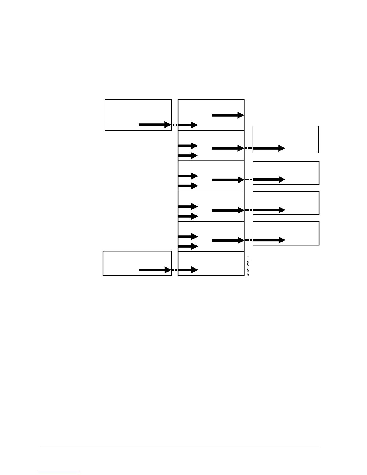
54 / 87
Siemens RDG400KN,RGD405KN Basic documentation CE1P3192en
Building Technologies 2017-02-17
To make this possible, the following conditions are predefined:
∂ Every device or subdevice is located within a zone
∂ Every data point (input or output) is assigned to a zone
∂ Every data point (input or output) has a precisely defined "Name"
Whenever an output and an input with the same "Name" are located in the same
zone, a connection is established automatically, as shown in the following diagram:
∂ For a detailed description of KNX (topology, bus supply, function and setting of
LTE zones, filter tables, etc.), refer to Basic Documentation "Communication via
the KNX bus for Synco 700, 900 and RXB/RXL" [6]
∂ LTE-Mode data points and settings are described in the Synco Application
Manual [12]
∂ To engineer and commission a specific system, use the Synco700 planning and
commissioning protocol (XLS table in HIT) [7]
RDG
Sensor
Outside temperature zone 31
Air distr zone 1
(With RMU basic type "P")
Geogr. zone 2.5.1
Refr. distr zone 1
Air demand
Outside temperature
Outside temperature
Air demand
Outside temperature zone 31
Air distr zone 1
Cool demand
Time Switch
Operating mode Operating mode
Chiller
Refr. distr zone 1
Cool demand
Geogr. zone 2.5.1 or 2.1.1
Room temperature
Heat distr zone 1
Heat demand
Boiler
Heat distr zone 1
Heat demand
Heat distr zone 2
Heat surface demand
Boiler
Heat distr zone 2
Heat surface demand
Air handling unit
Definitions
Engineering and
commissioning
Page 55
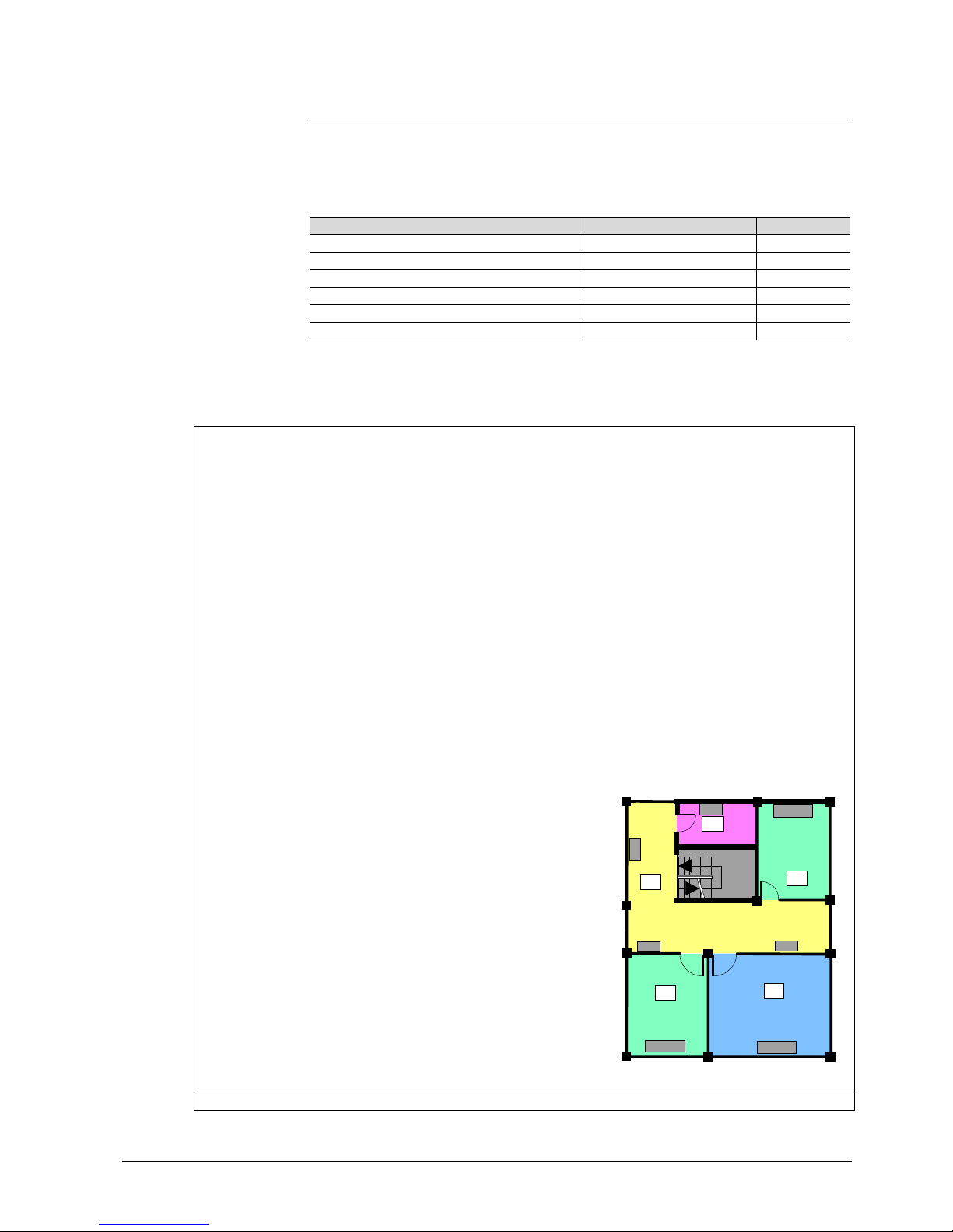
55 / 87
Siemens RDG400KN,RGD405KN Basic documentation CE1P3192en
Building Technologies 2017-02-17
3.10.3 Zone addressing in LTE-Mode (in connection with
Synco)
In cases where RDG..KNX room thermostats are used in LTE-Mode (e.g. in
connection with Synco), zone addresses need to be allocated.
The following zone addresses must be defined together with the Synco devices at
the planning stage depending on the application:
Short description
Factory setting
Parameter
Geographical zone (apartment) --- (out of service) P82
Geographical zone (room) 1 P83
Heat distribution zone heating coil --- (out of service) P84
Refr distribution zone cooling coil --- (out of service) P85
Heat distribution zone heating surface --- (out of service) P86
Air distribution zone --- (out of service) P87
"Subzone" of "Geographical zone" is fix 1 (not adjustable).
The device sends and receives LTE communication signals only if the zone
address is valid (not OSV = out of service).
The zones to be defined are as follows:
Geographical zone
(space zone)
(Apartment . Room . Subzone)
Apartment = ---, 1...126
Room = ---, 1...63
Subzone = fix 1
Zone in which an RDG..KNX thermostat is physically located. Other
room-specific devices may also be located in this zone.
Information exchanged in this zone is related specifically to the device
like operating mode, setpoints, room temperature, etc.
The designations "Apartment", "Room" and "Subzone" do not need to
be taken literally. For example, "Apartment" can be used to refer to a
group of rooms, floor or section of a building. "Room", however, really
does refer to a room.
Subzone is not used for HVAC devices. It is more relevant to other
disciplines, such as lighting. Subzone is fix at "1" and not visible.
The time switch information is expected from the same zone where
the thermostat is located (Residential).
If no time switch information is received from the same zone, the
thermostat uses the information received from the same apartment but
with room "1" A.1.1 (Office).
Example:
Commercial building
In a commercial building, the
time switch information is sent by
the RMB795 central control unit.
The zones are divided into socalled "Room groups" (e.g. 1...4),
where each "Room group" can
have an individual schedule. A
room thermostat in the same
"Room group" need to have the
same Apartment Address.
Legend:
D = device address (P81)
G = geographical zone (P82, P83)
(Apartment.Room.Subzone)
D: 001
G: 3.1.1
Meeting room
Office 1
Server room
Office 2
2
4
D: 002
G: 2. 1.1
D: 003
G: 2.2.1
D: 10
G: 1. 1.1
Corridor D: 12
G: 1.3.1
D: 11
G: 1. 2.1
D: 004
G: 4.1.1
1
2
3
3171z201
Heat distribution zone
Information related specifically to the hot water system in heating coils
Note
Page 56
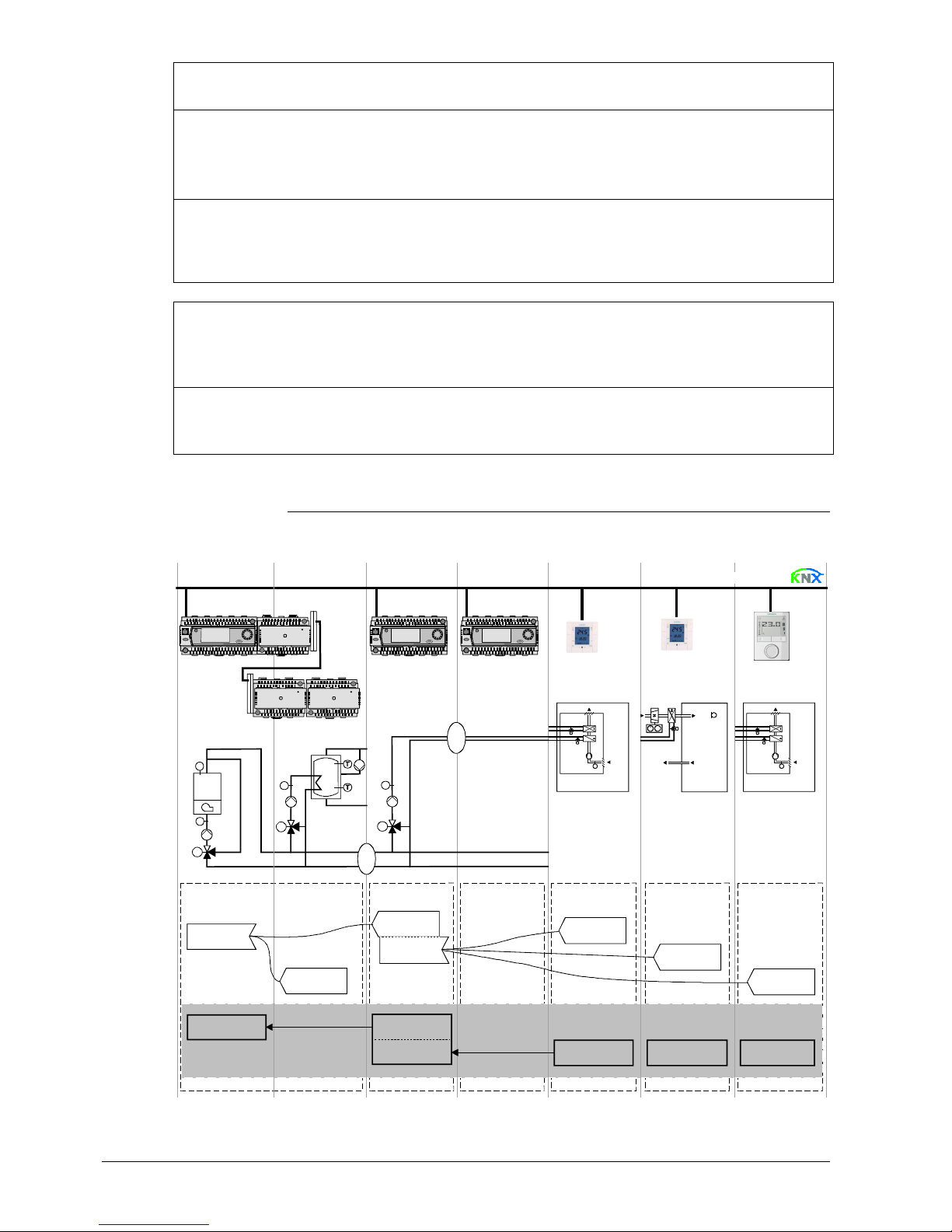
56 / 87
Siemens RDG400KN,RGD405KN Basic documentation CE1P3192en
Building Technologies 2017-02-17
heating coil
Zone = ---, 1...31
is exchanged within this zone. The zone also includes a Synco device
to process the information (e.g. RMH7.. or RMU7.. with changeover).
Heat distribution zone
heating surface
(radiator)
Zone = ---, 1...31
Information related specifically to the hot water system of a radiator is
exchanged within this zone (e.g. heating demand). This zone also
includes a Synco device to process the information (e.g. RMH7.. or
RMB7..).
Refrigeration
distribution zone
cooling coil
Zone = ---, 1...31
Information related specifically to the chilled water system is
exchanged within this zone (e.g. cooling demand). This zone also
includes a Synco device to process the information (e.g. RMU7..).
Air distribution zone
Zone = ---, 1...31
This distribution zone is for air applications (VAV, CAV). Information
related specifically to the air handling system is exchanged within this
zone (e.g. air demand). This zone also includes a Synco device to
process the information (RMU7.. basic type P).
Outside temp. zone
Zone = fix 31
Outside temperature received in outside temperature zone 31 will be/
can be displayed on the thermostat if commissioned accordingly (P07
= 2).
3.10.4 Example of heating and cooling demand zone
The building is equipped with Synco controls on the generation side and RDU../
RDG.. room thermostats on the room side.
RMH760 RMH760 RMB795
Konnex TP1
RDG...RDU...
RDF...
T
T
T
T
1
2
P3171Z01
Heat requistion
Heat dem and
Heat distr zone 1
Heat source
Controll er 1 Controller 2
Controller 3
Controll er 4 Controller 5 Controller 6
Controller 1 Controll er 2 Controller 3 Controller 4 Controller 5 Controller 6
Heating circuit
fan coil
Fan co il
room A
VAV box
room B
Fan coil
room C
DHW heating
Heat demand
Heat demand
Heat demand
Heat dem and
Heat requisti on
Heat distr zone
sourc e side: 1
Heat distr zone 2
Heat distr zone 2 Hea t di str zone 2
Heat distr zone 2
Setting values
MV MV
T
T T
Page 57

57 / 87
Siemens RDG400KN,RGD405KN Basic documentation CE1P3192en
Building Technologies 2017-02-17
In the case of a typical application, the individual RDU../RDG.. room thermostats –
when used with the RMB795 central control unit – signal their heat demand directly
to the primary controller (in the above example to the RMH760).
(1) and (2) designate the numbers of the distribution zone.
This type of application can analogously be applied to refrigeration distribution
zones.
3.10.5 Send heartbeat and receive timeout
In a KNX network, S-Mode and LTE-Mode communication objects can be exchanged
between individual devices. The Receive timeout defines the period of time within
which all the communication objects requested from a device is received at least
once. If a communication object is not received within this period of time, a
predefined value is used.
Similarly, the Send heartbeat defines the period of time within which all the
communication objects requested must be transmitted at least once.
Fixed times are specified as follows:
– Receive timeout: 31 minutes
– Send heartbeat: 15 minutes
Object [KNX obj. Nr.] I/O Minutes Default value
Room operating mode:
Time switch [12]
Receive 31 Comfort
Room operating mode:
Preselection [7]
Receive 31 Auto
Application mode [31] Receive 31 Auto
Individual zones can also be disabled (out of service) via control parameter if not
used. In disabled zones, the LTE signal is no longer periodically sent, and will
therefore reduce the bus load.
3.10.6 Startup
The application is restarted after every reset, so that all the connected motorized
valve actuators are synchronized (see "Control outputs", 0).
After a reset, it takes up to 5 minutes for all the connected room thermostats to
restart, thus avoiding network overloads when restarting. At the same time, it
reduces the load on the KNX network, since not all thermostats transmit data at the
same time. The delay (T
WaitDevice
) is determined by the thermostat's device address.
After the delay, the device starts to send.
Explanation relating to
the illustration
Note
LTE-Mode/S-Mode
Reducing the bus load
Startup response
Startup delay
Page 58
58 / 87
Siemens RDG400KN,RGD405KN Basic documentation CE1P3192en
Building Technologies 2017-02-17
3.10.7 Heating and cooling demand
In connection with Synco, the heating and/or cooling demand (for water) from each
room is transmitted to the BACS to provide the required heating or cooling energy.
An example for LTE-Mode is described in section 3.10.4.
In S-Mode, the current state signals of the control outputs are available.
3.10.8 Air demand
In connection with Synco, the air demand from each room is transmitted to the
BACS to provide the required air volume.
In S-Mode, the current state signal of the air damper is available.
3.10.9 Electric heater interlock by supply air controller
(LTE-Mode only)
To avoid overheating of an electric heater, sufficient flow of supply air must be
guaranteed. The thermostat features the function "Interlock of electric heater via
supply air controller", which is active when a supply air controller (e.g. Synco
RMU7..) is used in the system. The controller of the supply air fan sends the fan
status (StatusSATC) to the thermostat when the fan is running, after which the
electric heater is allowed to turn on if there is a call for heat.
When the supply air fan is not running, the electric heater is kept turned off, even
though there is a demand for heat.
The fan symbol is displayed when the supply air fan is running.
∂ Electric heater enable via local input X1-D1 or KNX overrides any release by this
interlock function, and vice versa (last intervention wins)
∂ After power-up of the thermostat, the electric heater is completely disabled for at
least 5 minutes or until a supply air controller is detected. If no supply air fan
controller is used, the electric heater is allowed to turn on if there is a demand
for heat
∂ The fan information is broadcast every 15 minutes or on change of value. If no
value is received any more, the thermostat deactivates the interlock function
after a timeout of 31 minutes
General rule: In case of insufficient air flow, the thermostat cannot protect the
electric heater against overtemperature. For this reason, the heater must be
equipped with a separate safety device (thermal cutout).
KNX
R
Heating output primary
Cooling output primary
KNX
R
Control output VAV
Notes
Caution
Page 59
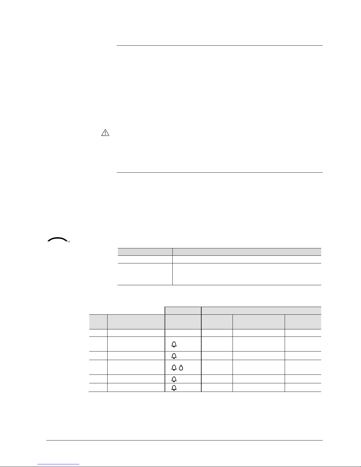
59 / 87
Siemens RDG400KN,RGD405KN Basic documentation CE1P3192en
Building Technologies 2017-02-17
3.10.10 Primary fan overrun after switching off the electric
heater
To avoid overheating of the electric heater after it has been switched off, the air
flow must be maintained for a while.
In connection with a supply air controller (e.g. Synco RMU7..) this will be
automatically ensured by exchanging the necessary information. The controller of
the supply air fan will only switch off the supply air fan when all electric heaters are
cooled off.
The cool off time of the electric heater can be adjusted for each heater via P54
(factory setting is 60 seconds).
General rule: In case of insufficient air flow, the thermostat cannot protect the
electric heater against overtemperature. For this reason, the heater must be
equipped with a separate safety device (thermal cutout).
3.10.11 Fault function on KNX
If a fault occurs (e.g. digital fault input, dewpoint, communication configuration,
etc.), a fault is sent on the bus.
An RDG.. thermostat listens on the bus and sends its fault when it has the highest
alarm priority. This ensures that the management station does not miss any alarms.
If alarms occur at the same time, the alarm with the highest priority is first displayed
and sent on the bus.
Fault transmission is different in LTE- and S-Mode:
S-Mode LTE-Mode
Fault state Alarm info (error code and internal information)
Fault information
(internal
information)
Alarm text (default text can be edited with ACS tool)
The table below shows the error code and default alarm texts:
Thermostat Fault information on the bus
Prio Fault Display Error code Default fault text
Text
adjustable *)
- No fault --- 0 No fault
1 Bus power supply**)
bus
5000 No bus power
supply
---
2 Device address error Addr 6001 >1 id device address ---
3 Condensation 4930 Condensation in the
room
4 External fault input X1 AL1 9001 Fault input 1
5 External fault input D1 AL3 9003 Fault input 3
*) D efault alarm texts are stored in the thermostat’s non-volatile memory and can be adjusted using
the ACS t ool
**) This error will not be s ent on the bus (because there is no bus! )
Note
Caution
KNX
R
Page 60

60 / 87
Siemens RDG400KN,RGD405KN Basic documentation CE1P3192en
Building Technologies 2017-02-17
∂ Priority order is #1…5
∂ External faults #4…5: If faults are active, the display shows AL1, AL3
alternating. On the bus, only the fault with the highest priority is sent
A supervisor alarm system may command the thermostat to stop sending faults to
the bus via the communication object "Fault transmission" (disable/enable).
This has no impact on the local display of faults.
After a timeout of 48 hours, sending of faults will automatically be enabled again.
3.10.12 Emergency control (LTE-Mode only)
In case of smoke or fire, the air damper can be overridden via KNX.
The necessary information is provided by function block "HVAC Emergency Mode".
The table below describes the behavior of the controller output:
# Data point value Air damper
0 Normal Normal operation
1 EmergPressure Fully open
2 EmergDepressure Fully closed
3 EmergPurge Fully open
4 EmergShutdown Fully closed
5 EmergFire Fully closed
Emergency signals have the highest priority and command the control output
accordingly. Any ongoing function like fan-overrun, etc., is stopped immediately.
The priority is as follows:
1. Smoke (Emergency 1...4)
2. Fire (Emergency 5)
3. Fan overrun (Emergency 0 and electric heater fan overrun function is
active)
4. Normal operation (Emergency 0 and operation by operating mode button)
3.10.13 Application with VAV compact controller
(KNX LTE-Mode only)
For applications with RDG.. and VAV compact controller (KNX LTE-Mode), the
information (control signal, current air damper position) is transmitted on the KNX
bus. The communication between the devices is established by setting the KNX
parameters in the thermostat and in the VAV compact controller.
KNX parameter RDG.. GDB..KN GDB..KN
KNX address 0.1.2 0.1.3 0.1.4
Master/slave Master Slave
Type of damper actuator Supply air Extract air
Geographical zone (apartment) 1 1 1
Geographical zone (room) 1 1 1
Air distribution zone 5 5 5
For information on applications with supply air and extract air, refer to section 3.4.1.
For details on KNX parameters in LTE-Mode, refer to section 3.10.3.
Priority of alarms
KNX
R
Fault transmission
Example
Page 61

61 / 87
Siemens RDG400KN,RGD405KN Basic documentation CE1P3192en
Building Technologies 2017-02-17
3.11 Communication objects (S-Mode)
3.11.1 Overview
KNX
R
Page Object # and name Thermostat Object # and name Page
13 1 System time
13 3 Time of day
13 38 Outside temperature 21 Room temperature *) 13
18 12 Room operating mode:
Time switch
1)
16 Room operating mode:
State
1)
16
18 7 Room operating mode:
Preselection
1)
24 Room temperature:
Current setpoint
27
17, 19
,
51
20 Room operating mode:
Window state
25 Control output VAV 58
27 22 Room temperature:
Comfort basic setpoint
26 Heating output primary
2)
58
27 23 Room temperature:
Comfort setpoint
27 Cooling output primary
2)
58
35 31 Application mode 37 D1 52
52 28 Enable electric heater 32-33 X1 (temperature/digital) 52
31, 51 30 Supply air temperature 36 U1 (0...100%) 52
51
29 Heating/cooling ch'over
2)
60 6 Fault transmission 5 Fault state 33, 59
20
39 Presence detector
3)
27
40 Economy heating setpoint
3)
27
41 Economy cooling setpoint
3)
66
42 Supply air: limit value min
3)
66
43 Supply air: limit value max
3)
66
44 CO2 concentration
3)
4 Fault information 33, 52,
59
Input communication object
Output communication object
Input and output communication object
1) 8-bit and 1-bit object available, selectable via parameter in ETS
2) Availability d epending on selected application/function
3) Only on RDG405KN
*) Transmit only on RDG400KN
Transmit and Receive on RDG405KN
Page 62
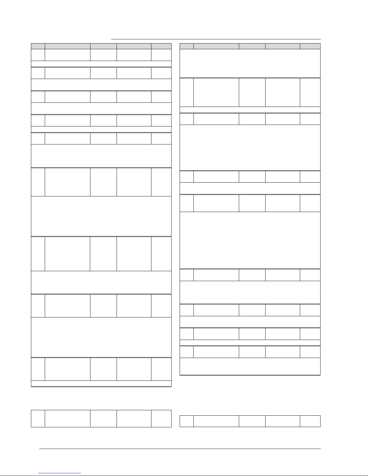
62 / 87
Siemens RDG400KN,RGD405KN Basic documentation CE1P3192en
Building Technologies 2017-02-17
3.11.2 Description of communication objects
Obj Object name Function Type/length Flags
1 System time Time and
date
19.001
8 Byte
CWU
System time for display on the thermostat (s ee P07 (3 or 4))
3 Time of day Time and
date
10.001
3 Byte
CWU
Another object for rec eiving the time of day for display on the
thermostat (see P07 (3 or 4))
4 Fault information Alarm
Info
219.001
6 Byte
CT
Common alarm output. If an alarm occurs, the alar m number is
transmitted
5 Fault state Faulty/
normal
1.005
1 bit
CT
Common alarm output. If an alarm occurs, the alarm flag is s et
6 Fault
transmission
Enable/
disable
1.003
1 bit
CWU
A supervisor alarm system can dis able the broadcasting of alarms
by the devic es. This has no impact on the local display of alarms.
After a timeout of 48 hours, the sending of faults will automatically
be enabled again.
7 Room operating
mode:
Preselection
Auto
Comfort
PreComf.
Economy
Protec tion
20.102
1 Byte
CWTU
Controls the room operating mode selection of the thermostat via
bus.
The command can als o be submitted as f our 1-bit c ommunic ation
objects (8...11). The last interaction wins – either from local
operating mode button or via bus.
Note: The thermostat changes Prec omfort either into Economy or
Comfort (s electable via P88).
8
9
10
11
Operating mode:
Preselection
Auto
Comf
Eco
Prot
Trigger 1.017
1 bit
CW
Switch room operating mode to either Auto, Comfort, Ec onomy or
Protection.
The last interaction wins – either fr om the local operating mode
button or via bus.
12 Room operating
mode: Time
switch
Comfort
Economy
PreComf.
Protec tion
20.102
1 Byte
CWU
This information is provided by a c entral time switch or a
supervisor and defines the actual HVAC operating mode.
The command can als o be submitted via three 1-bit
communication objects (13...15).
Protection mode has the highest priority and c annot be overridden.
Note: The thermostat changes Prec omfort either into Economy or
Comfort (s electable via P88).
13
14
15
Time switch
Comfort
Economy
Protection
Trigger 1.017
1 bit
CW
Switch the HVAC mode to eit her Comfort, Economy or Pr otection.
16 Room operating
mode: State
Comfort
Economy
Protec tion
20.102
1 Byte
CRT
Obj Object name Function Type/length Flags
Effective r oom operating mode used by the thermostat
(considering time switch, user selection, window c ontact, etc.) This
state information is available via one 8-bit enumeration or three 1bit communication objects (17...19). Note: The thermostat does not
support Pr ecomfort mode.
17
18
19
Room operating
mode:
State Comfort
State Economy
State Protection
ON
OFF
1.002
1 bit
CT
Corresponding c ommunic ation object sends "True"
20 Window state Open
Closed
1.019
1 bit
CWU
The thermostat is s et to Economy mode if value "1" (open) is
received. It s witches back to the previous mode when the value is
"0" (closed).
"Window state" is sent e.g by a KNX switch or a KNX presence
detector. It has the same effect as the local operating mode
switchover contact X1, D1 (P38, P42).
Only one input source must be us ed, either local input X1-D 1 or
the KNX bus.
21 Room temperature
(RDG400K N)
Temp.
value
9.001
2 Bytes
CRT
The value of the room temperature acquired via built-in or extern al
sensor is available via this communication object.
22 Room tempera-
ture: Comfort
basic setpoint
Temp.
value
9.001
2 Bytes
CWU
If function "Temporary setpoint" is enabled via P69, then – after an
operating mode change – the setpoint adjustments made by the
user and via communic ation object 23 is dismissed and the
thermostat will be reset to the Comfort basic s etpoint.
Note: Setpoints that have been changed via the local HMI may be
overwritten during a system s tartup from a central master
controller, e.g.RMB795.
The Comfort basic setpoint is stored in EEPROM (see section
3.3.2).⇓ The serv ice life of the EEPROM depends on the number
of write cycles. Never write this communication object cyclically!
23
Room temperature:
Comfort setpoint
Temp.
value
9.001
2 Bytes
CWTU
Communic ation object used to shift the s etpoint used by the
thermostat (see section 3.3.2). Same priority as local setpoint shift
on the thermostat. The last intervention wins.
Note: The Comfort basic setpoint (object 22) will not be changed.
24
Room temperature:
Current setpoint
Temp.
value
9.001
2 Bytes
CRT
Current setpoint, including shift, compensation, etc., used by the
thermostat for temperature control
25 Control output
VAV
0…100% 5.001
1 Byte
CRT
Indicates the position of the air damper. E.g. single-d uct
26 Heating output
primary
0…100% 5.001
1 Byte
CRT
Indicates the position of the heating actuator of the electric
heating. E.g. single-duct with electric heater application: Output of
the electric heater.
27 Cooling output
primary
0…100% 5.001
1 Byte
CRT
Page 63
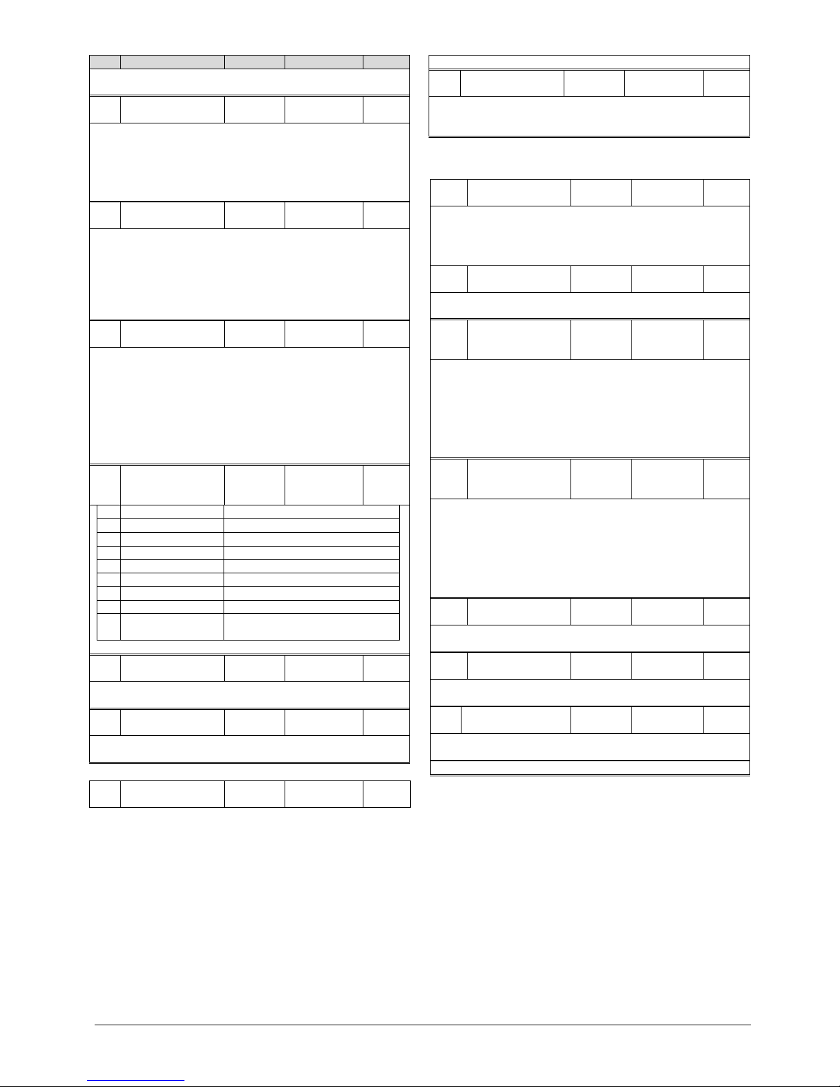
63 / 87
Siemens RDG400KN,RGD405KN Basic documentation CE1P3192en
Building Technologies Error! Use the Home tab to apply Überschrift 1 to the text that you want to appear here. 2017-02-17
Obj Object name Function Type/length Flags
Indicates the position of the cooling actuator of the first stage.
E.g. single-duct with h/c coil application: Output of the cooling coil
28 Enable electric
heater
Enable/
disable
1.003
1 bit
CWU
An electric heater can be disabled with this c ommunic ation object
(e.g. to meet tariff regulations).
The same function is also avai lable via local multifunctional input
X1-D1 (P38, P42).
Only one input source must be used, either local input X1/D1or
KNX bus.
29 Heating/cooling
changeover
Heating/
cooling
1.100
1 bit
CWU
Changeover information transmitted via bus. Only available with
application "Single-duct with heating/cooling coil".
Default: Current mode before power down.
The same function is also avai lable via local multifunctional input
X1-D1 (P38, P42).
Only one input source must be used, either local input X1/D1or
KNX bus.
30 Supply air
temperature
Temp.
value
9.001
2 Byte
CWU
The supply air temperature s ent by the supply air c ontroller
indicates whether cold or hot air is supplied (for VAV changeover).
The contr oller determines the necessity to open or clos e the air
damper acc ording to the supply air temperature, the room temperature setpoint, and the current room temperature.
The same function is also avai lable via local multifunctional input
X1-D1 (P38, P42).
Only one input source must be us ed, either local input X-D1or KNX
bus.
31 Application mode HVAC
control
mode
20.105
1 Byte
CWU
0 Auto (default) Heating and/or cooling
1 H eat Heating only
2 Morning warmup* Heating only
3 Cool Cooling only
4 Night purge Open air damper fully
5 Precool* Cooling only
6 OFF Neither heating nor c ooling
8 Emergency heat* Heating only
9 Fan only Open air damper fully (= night
purge)
* Function handled like Heat ( 1) or Cool (3)
32 X1: Temperature Temp.
value
9.001
2 Byte
CRT
Indicates the values of the temperature sens ors connected to the
local inputs X1
3337X1: Digital
D1: Digital
ON
OFF
1.001
1 bit
CRT
Indicate the status of the digital inputs (adjusted via P39…P 43)
including considering the operating action
36 U1: 0..10V 0…100% 5.001
8 bit
CRT
DC 0…10 V at input U1 is indic ated as a value 0…100%
38 Outside
temperature
Temp.
value
9.001
2 Byte
CWU
The outside temperature acquired by a KNX sensor can be
displayed on the thermost at, if P07 " Additional user information” is
set = 2 (outside temperature).
The following objects are only available on RDG405KN
21 Room temperature
(RDG405K N)
Temp.
value
9.001
2 Bytes
CRT
The value of the room temperature measured via built-in or
external sensor is available on bus when this c ommunic ation
object is set to Transmit.
By setting the object to Receive, the thermostat receives and
works with the room t emperat ure from an external sensor
39 Presence Sensor 1.018
1 bit
CWU
Room oper ating mode : Presence detector
Switch the d evice to Comfort mode
40 Room tempera-
ture: economy
heating setpoint
Temp.
value
9.001
2 bytes
CWU
Communication object to adjust the Ec onomy heating setpoint
used by the thermostat (see section 3.3.2). It directly changes the
value of the local parameter "Economy setpoint" P11.
S-Mode object needs to be enabled by setti ng Room temp.:
Economy setpoints to as group object in ETS.
The Economy setpoint is stored in EEPROM. The service lif e of
the EEPROM depends on the number of write cycles. Never write
this communication object cyclic ally.
41 Room tempera-
ture: Economy
cooling setpoint
Temp.
value
9.001
2 bytes
CWU
Communication object to adjust the Economy cooling setpoint
used by the thermostat (see section 3.3.2). It directly changes the
value of the local parameter "Economy setpoint" P12.
S-Mode object needs to be enabled by setti ng Room temp.:
Economy setpoints to as group object in ETS.
The Economy setpoint is stored in EEPROM. The service lif e of
the EEPROM depends on the number of write cycles. Never write
this communication object cyclic ally.
42 Supply air : limit
value min (%)
0…100% 5.001
1 Byte
CWU
The output signal f or the air f low can be limited to a minimum
value (P63)
43 Supply air: Limit
value max. ( %)
0…100% 5.001
1 Byte
CWU
The output signal f or the air flow can be limited to a maximal value
(P64)
44 IAQ: CO
2
concentration
ppm
value
2 bytes CWT
CO2 concentration in ppm.
Range :0…5000 ppm
Page 64
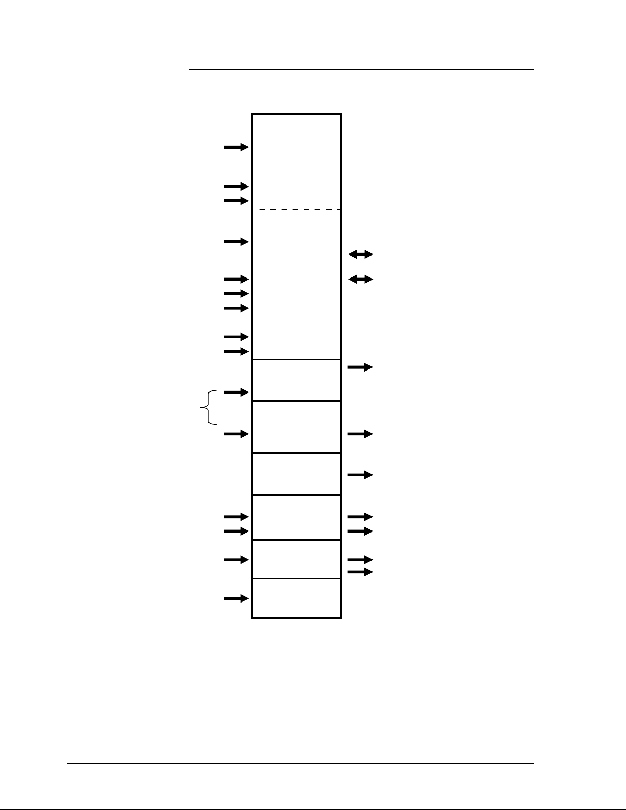
64 / 87
Siemens RDG400KN,RGD405KN Basic documentation CE1P3192en
Building Technologies 2017-02-17
3.12 Communication objects (LTE-Mode)
Communication objects RDG4.. Communication objects
Geographical zone
A.R.S
Room operating mode:
Time switch
(Time switch zone)
X.1.1/X.Y.1
Application mode
Emergency mode
Room operating mode:
Preselection
Geographical zone
A.R.S
X.Y.1
Room temperature
Comfort setpoint
IAQ (ppm)
3)
Setpoints heating
Setpoints cooling
Setpoint shift heating
Setpoint shift cooling
Heat distr. zone
Heating coil energy
demand
1) 2)
heating coil
Heating/cooling
changeover
2)
Ref. distr. zone
cooling c oil
Cooling coil energy
demand
1) 2)
Heat distr. zone
heating surface
Energy demand heating
surface
1) 2)
Distribut ion zone air
1)
Supply air temperature
Energy demand air
1)
Status SATC
Air damper position
2)
Broadcast
Fault transmission Fault information
Fault text
Outside air t emp. zone
Outside temperature fix 31
Note:
1) Available depending on selected application
2) Available only on RDG..
3) Only for RDG405KN
Page 65

65 / 87
Siemens RDG400KN,RGD405KN Basic documentation CE1P3192en
Building Technologies 2017-02-17
3.13 Control parameters
A number of control parameters can be readjusted to optimize the control
performance. This can be done on the thermostat via HMI or via commissioning/
operating tool. These parameters can also be set during operation without
opening the unit.
In the event of a power failure, all control parameter settings are retained.
The control parameters are assigned to 2 levels:
∂ Service level, and
∂ Expert level including communications, diagnostics and test
The Service level contains a small set of parameters to set up the thermostat for
the HVAC system and to adjust the user interface. These parameters can be
adjusted any time.
Change parameters at the Expert level carefully, as they impact the thermostat’s
control performance and functionality.
3.13.1 Parameter setting via local HMI
1. Hold down both the left and right buttons simultaneously for 4 seconds.
Release them, and hold the right button again within 2 seconds until P01
displays.
Continue with step 2.
1. Hold down both the left and right buttons simultaneously for 4 seconds.
Release them, and hold the left button again within 2 seconds until the
temperature disappears.
Turn the rotary knob counterclockwise minimum ½ rotation. Pxx displays.
Continue with step 2.
2. Select the required parameter by turning the rotary knob.
3. Press button (OK); the current value of the selected parameter starts
blinking and can be changed by turning the rotary knob.
4. Press button (OK) to confirm the adjusted value or press button
(Esc) to cancel the change.
5. If you wish to adjust additional parameters, repeat steps 2…4.
6. Press button (Esc) to leave the parameter setting mode.
The factory setting for the control parameters can be reloaded via P71 by
changing the value to "On". Confirm by pressing the right button.
Then, 8888 displays during reloading.
Enter only Service level
Enter Expert level with
diagnostics and test
Adjusting parameters
Resetting parameters
Page 66

66 / 87
Siemens RDG400KN,RGD405KN Basic documentation CE1P3192en
Building Technologies 2017-02-17
3.13.2 Parameter setting/download via tool
Control parameters can be adjusted via bus either by parameter download
during commissioning or during normal operation with a tool like the ACS.
With the ACS tool, the parameters can be changed …
– during commissioning via parameter download (all parameters),
– during normal operation via Popcard (most parameters).
Most parameters can be changed during normal operation using the OZW772
web server.
Only the parameters for the device address can be downloaded via ETS. This is
to simplify matters and to avoid conflicts.
It allows you to further engineer communication objects of an RDG.. previously
commissioned via local HMI or the ACS tool (assigning communication objects
to group addresses).
∂ The basic application can only be changed via parameter download with the
ACS tool
∂ The RDG..KNX room thermostats require version ETS4 or higher/ACS790
The connection of a KNX commissioning/operating tool to the RDG.. is
described in section 4.2.
ACS
OZW772 web server
ETS
Notes
Connecting a KNX tool
Page 67
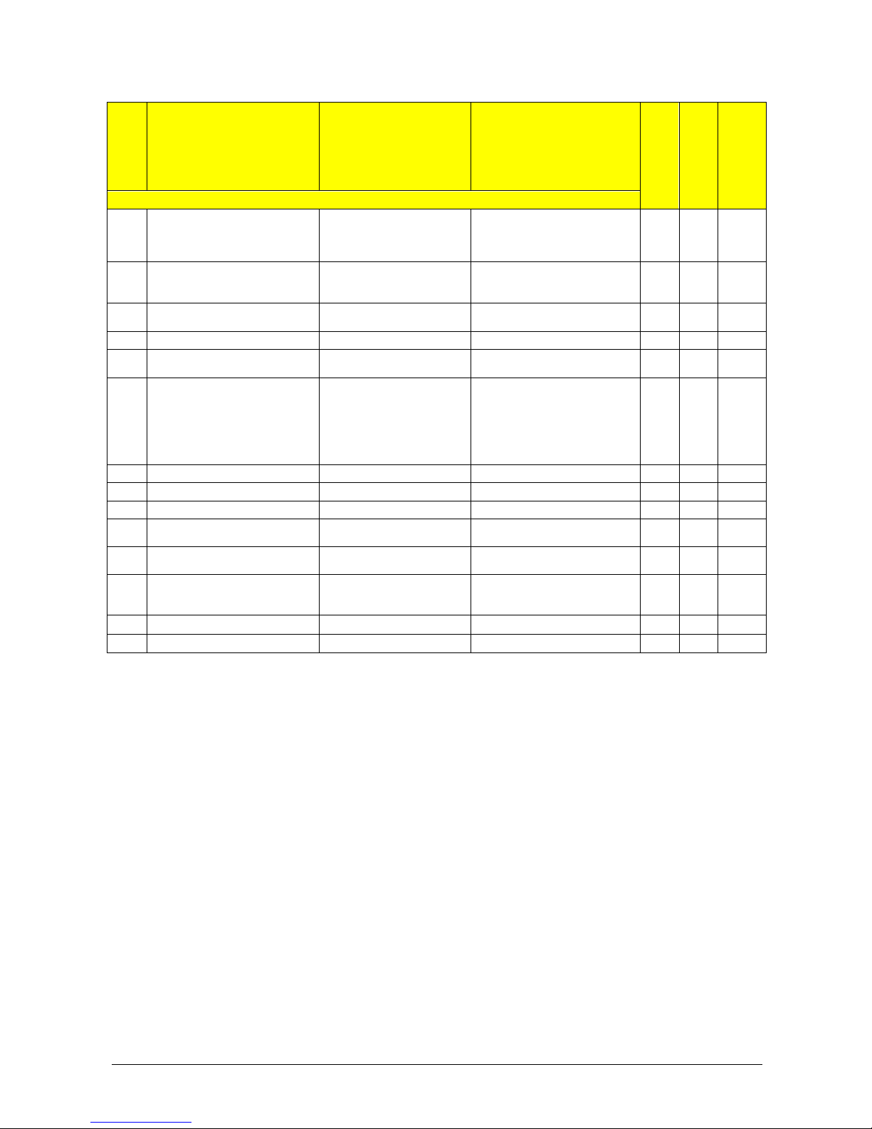
67 / 87
Siemens RDG400KN,RGD405KN Basic documentation CE1P3192en
Building Technologies 2017-02-17
3.13.3 Parameters of the Service level
Parameter
Name Factory setting Range
RDG400KN
RDG405KN
Dependencies
Service level
P01 Control sequence 1 = Cooling only 0 = Heating only
1 = Cooling only
2 = H/C changeover manual
3 = H/C changeover auto
P02 Operation via room op selector 1 1 = Auto - Protection
2 = Auto - Comfort - Ec onomy -
Protec tion
P04 Unit C (0) C = degrees Celsius
F = degrees Fahrenheit
P05 Measured value correction 0 K – 3...3 K
P06 Standard display 0 0 = Room temperature
1 = Setpoint
P07 Additional display information
RDG400KN (r ange 0...4)
RDG405KN (r ange 0... 4, 6,7)
0
0 = --- (no display)
1 = °C and °F
2 = Outside temperature (via bus)
3 = Time of day (12 h) (via bus)
4 = Time of day (24 h) (via bus)
6 = CO2 concentration [ppm]
7 = CO2 symbols
P08 Comfort basic setpoint 21 °C 5...40 °C
P09 Comfort setpoint minimum 5 °C 5...40 °C
P10 Comfort setpoint maximum 35 °C 5...40 °C
P11 Economy heating setpoint 15 °C OFF, 5...WCoolEc o;
WCoolEco = 40 °C max.
P12 Economy cooling setpoint 30 °C OFF, WHeatEco...40 °C;
WHeatEc o = 5C min.
P14 Button lock 0 0 = Unlocked
1 = Aut o lock
2 = Manual lock
P19 CO2 (VOC) Setpoint 1000
OFF(0)…5 000 ppm
X
P20 CO2 (VOC) P-band Xp 400
10…2000 ppm
X
Parameter display depends on selected application and function.
Note
Page 68

68 / 87
Siemens RDG400KN,RGD405KN Basic documentation CE1P3192en
Building Technologies 2017-02-17
3.13.4 Parameters of the Expert
level with diagnostics and
test
Parameter
Name Factory setting Range
RDG400KN
RDG405KN
Dependen-
cies
Expert level
P30 Heat P-band Xp/switching diff 2 K 0.5…6 K
P31 Cool P-band Xp/switching diff 1 K 0.5…6 K
P32 Radiator P-band Xp/swi diff 2 K 0.5…6 K
Appl
P33 Dead zone Comfort mode 2 K 0.5…5 K
Appl
P35 Integral action time Tn
RDG400KN
RDG405KN
5 min
45 min
0…10 min
0…120 min
P46, P47
P36 H/C ch'over swi point cooling 16 °C 10…25 °C
P38
P37 H/C ch'over s wi point heating 28 °C 27… 40 °C
P38
P38 Input X1
RDG400KN
(range 0..3 [ECO]..8)
RDG405KN
(range 0..3 [PROT]..10)
1: = Ext. sens or
0 = --- (no function)
1 = Room temp ext. sensor/
return air temp (AI)
2 = H/C changeover (AI/DI)
3 = Operat. mode contact [ECO],
window contact [PROT] (DI)
4 = Dewpoint sensor (DI)
5 = Enable electric heater (DI)
6 = Fault input (DI)
7 = Monitoring input (Digital)
8 = Monitoring input (Temp)
10 = Presence detector (DI)
P39 Normal position input X1 0 (NO) 0 = N ormally open/open
1 = Normally closed/close
P38
P40 Input U1 0 0 = No function
1 = Input for air damper position
2 = input CO2 sensor
X
P42 Input D1
RDG400KN
(range 0..3 [ECO]..7)
RDG405KN
(range 0..3 [PROT]..10)
3 =
Operating mode
contact (RDG400KN)
Window c ontact
(RDG405KN
0 = --- (no function)
2 = H/C changeover (DI)
3 = Operat. mode contact [ECO],
window contact [PROT] (DI)
4 = Dewpoint sensor (DI)
5 = Enable electric heater (DI)
6 = Fault input (DI)
7 = Monitoring input (Digital)
10 = Presence detector (DI)
P43 Normal position input D1 0 (N.O.) 0 = Normally open/open
1 = Normally closed/close
P42
P44 Actuator running time Y1/Y2 150 s 20…300 s
P46
P46 Output Y1/Y2 On/Off (1) 0 = 3-position
1 = 2-position - ON/OFF
2 = 2-position - PW M
Appl
P47 Controller output VAV 0 = DC 0…10 V 0 = DC 0…10 V
1 = 3-position
Appl
P51 Flow temp limit floor heating Off Off, 10...50 °C
P38
P54 Fan overrun time 60 s 0…360 s
P63 Sup ply air limit value min 0% 0…P64 (%)
P64 Sup ply air limit value max 100% P63...100 (%)
P65 Protection heating setpoint 8 °C OFF, 5…W CoolProt;
WCoolProt = 40 °C max.
P66 Protection cooling setpoint Off OFF, WHeatProt… 40;
WHeatProt = 5°C min.
P68 Temporary Comfort mode 0 (= Off) 0...360 min
P02
P69 Temporary Comfort setpoint Off OFF = Disabled
ON = Enabled
Page 69

69 / 87
Siemens RDG400KN,RGD405KN Basic documentation CE1P3192en
Building Technologies 2017-02-17
Parameter
Name Factory setting Range
RDG400KN
RDG405KN
Dependen-
cies
Expert level
P71 Restore f actory setting OFF OFF = Disabled
ON = Reload start
8888 is displayed f or 3 seconds
during reload process
Parameter
Name Factory setting Range
RDG400KN
RDG405KN
Dependencies
Communications
P81 Device address 1) 255 1…255
P82 Geographic al zone (apartment) 2) --- ---, 1...126
P83 Geographic al zone (room) 2) 1 ---, 1...63
P84 Heat distr zone heating coil --- ---, 1...31
Appl, P01
P85 Refrig distr zone cooling coil --- ---, 1...31
Appl, P01
P86 Heat distr zone heating surface --- ---, 1...31
Appl
P87 Air distribution zone --- ---, 1...31
P88 Trans formati on Precomfort 0 0 = Economy
1 = Comf ort
P46, P47: Setting to 2-position or 3-position is made with DIP switches 4 and 5
1) Physical address = Area.Line.DeviceAddress. Factor y setting for Area = 0, Line = 2.
Can be changed by special management service e.g. fr om line coupler or via ACS tool
2) Type = geographical zone A.R.S. In RDG subzone = fixed value 1
Parameter
Name Range
RDG400KN
RDG405KN
Dependencies
Diagnostics and test
d01 Application number 0 = --- (no application)
1 = Single-duct
2 = Single-duct with electric heater
3 = Single-duct with radiator
4 = Single-duct with heating/cooling coil
d02 X1 state --- = No function (P38 = 0)
0 = Not activated (for DI)
1 = Activated (DI)
0…49 °C = Current temp. value (for AI)
00 = H/C input shorted
100 = H/C input open
d03 U1 status (RDG405KN)
DC 0…10V;
"---" means not available
d04 D1 state 0 = Not activated (for DI)
1 = Activated (DI)
00 = H/C input shorted
100 = H/C input open
d05 Test mode for checking the Y1/Y2 actuator's
running direction
3)
"---" = No signal on outputs Y1 and Y2
OPE = Output Y1 forc ed opening
CLO = Output Y2 forced closing
P46
d07 Software version Ux.xx is displayed
3) This parameter can only be quit when the setting is back at "---".
Press the left button to escape
Notes
Page 70
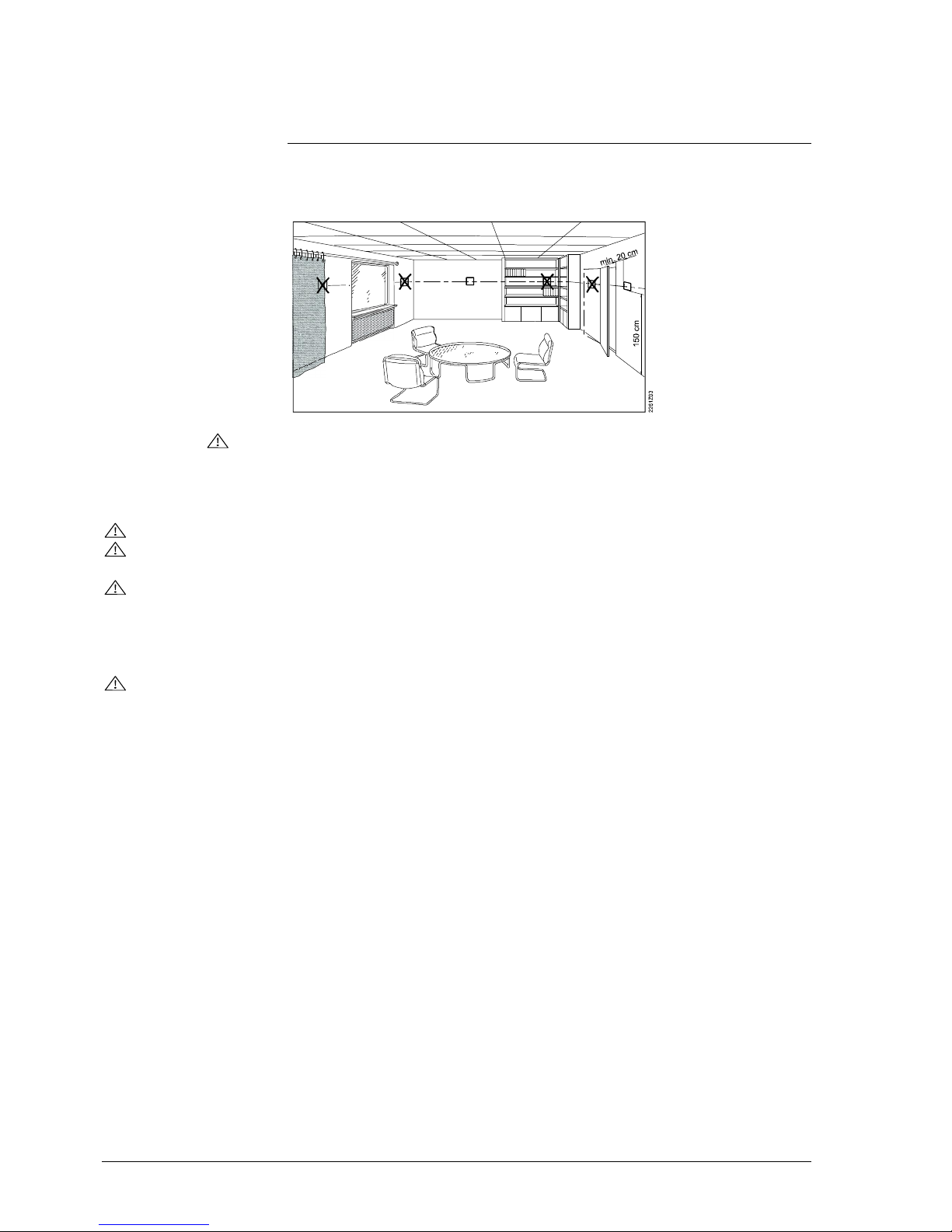
70 / 87
Siemens RDG400KN,RGD405KN Basic documentation CE1P3192en
Building Technologies 2017-02-17
4. Handling
4.1 Mounting and installation
Do not mount on a wall in niches or bookshelves, behind curtains, above or near
heat sources, or exposed to direct solar radiation. Mount about 1.5 m above the
floor.
Mounting
∂ Mount the room thermostat in a clean, dry indoor place without direct air flow
from a heating/cooling device, and not exposed to drip or splash water
Wiring
See Mounting Instructions M3192 [3] enclosed with the thermostat.
∂ Comply with local regulations to wire, fuse and earth the thermostat
∂ The power supply line must have an external fuse or circuit breaker with a rated
current of no more than 10 A
∂ Isolate the cables of inputs X1-M, U1-G0 and D1-GND for AC 230 V if the
conduit box carries AC 230 V mains voltage
∂ Inputs X1-M or D1-GND: Several switches (e.g. summer/winter switch) may be
connected in parallel. Consider overall maximum contact sensing current for
switch rating
∂ Isolate the cables of KNX communication input CE+/CE- for AC 230 V if the
conduit box carries AC 230 V mains voltage
∂ Disconnect the unit from power supply before removing it from its mounting
plate
Page 71

71 / 87
Siemens RDG400KN,RGD405KN Basic documentation CE1P3192en
Building Technologies 2017-02-17
4.2 Commissioning
The room thermostats are delivered with a fixed set of applications.
Select and activate the required application during commissioning using one of
the following tools:
– Local DIP switch and HMI
– Synco ACS
– ETS
(Parameter and application download with ETS will be implemented later)
Set the DIP switches before snapping the thermostat to the mounting plate, if
you want to select an application via DIP switches.
All DIP switches need to be set to OFF (remote configuration), if you want to
select an application via commissioning tool.
After power is applied, the thermostat resets and all LCD segments blink, indicating that the reset was correct. After the reset, which takes about 3 seconds, the
thermostat is ready for commissioning by qualified HVAC staff.
If all DIP switches are set to OFF, the display reads NO APPL to indicate that
application commissioning via tool is required.
Each time the application is changed, the thermostat reloads the factory setting
for all control parameters, except for KNX device and zone addresses!
Connect the Synco ACS or ETS tool to the KNX bus cable at any point for
commissioning:
ACS and ETS require an interface:
– RS232 KNX interface (e.g. SiemensUP146/02, UP152)
– OCI702 USB-KNX interface
An external KNX bus power supply is required if an RDG.. is connected directly
to a tool (ACS or ETS) via KNX interface.
Applications
DIP switches
NO APPL
Note
Connect tool
Note
Page 72

72 / 87
Siemens RDG400KN,RGD405KN Basic documentation CE1P3192en
Building Technologies 2017-02-17
The thermostat's control parameters can be set to ensure optimum performance
of the entire system (see section 3.11).
The parameters can be adjusted using …
– the local HMI
– Synco ACS
– ETS
∂ The control sequence may need to be set via P01, depending on the
application. The factory setting is as follows:
Application Factory setting P01
Single-duct, single-duct with heating/cooling coil 1 = cooling only
Single-duct with electric heater, single-duct with
radiator
Not adjustable
∂ Recalibrate the temperature sensor if the room temperature displayed on the
thermostat does not match the room temperature measured (after min. 1 hour
of operation). To do this, change P05
∂ We recommend to review the setpoints and setpoint ranges (P08…P12) and
change them as needed to achieve maximum comfort and to save energy
The addressing mode helps identify the thermostat in the KNX network during
commissioning.
Press left and right buttons simultaneously for 6 seconds to activate addressing
mode, which is indicated on the display with PrOg.
Addressing mode remains active until thermostat identification is complete.
Assign the device address (P81) via HMI, ACS or ETS.
With device address set to 255, the communication is deactivated (no exchange
of process data).
Use ETS to assign the KNX group addresses of the thermostat's communication
objects.
Each device bears a unique KNX serial number at the rear.
An additional sticker with the same KNX serial number is enclosed in the packaging box. This sticker is intended for installers for documentation purposes.
Control parameters
Control sequence
Recalibrating the
sensor
Setpoint and range
limitation
Addressing mode
Assigning the KNX
device address
Assigning the KNX
group addresses
KNX serial number
Page 73

73 / 87
Siemens RDG400KN,RGD405KN Basic documentation CE1P3192en
Building Technologies 2017-02-17
4.3 Operation
See also Operating Instructions B3192 [2] enclosed with the thermostat.
1. Operating mode selector/Esc
2. Protection and OK
3. Rotary knob to adjust setpoints
and parameters
User action
Effect, description
Normal operation Actual operating mode and state are
indicated by symbols.
Press any button
(thermostat in normal operation)
Enter operating mode selection;
backlit LCD turns on, all possible mode
symbols turn on, indicator element (arrow)
appears on the current mode/state.
Press left button Change operating mode (indicator element
(arrow) changes to the next mode symbol.
After the last press and a timeout of 3
seconds, the newly selected mode is
confirmed, the other elements disappear.
After a timeout of 20 seconds, the LCD
backlight turns off.
Press left button (P01 = 2) Toggle between heating and cooling.
Press left button while "Operating
mode" via bus is Economy or while
operating mode switchover contact is
activated
Activate "Extend Comfort mode"
(for details, see page 20).
Keep left button depressed and
turn rotary knob clockwise/counterclockwise
Activate timer "Extend presence"/"Extend
absence" and set the time (for details, see
page 20).
Press right button >3 seconds Activate/deactivate button lock.
Press right button Set thermostat to Protection mode or back
to the previous operation mode.
Turn rotary knob Adjust the room temperature Comfort
setpoint.
Hold down both the left and right
buttons simultaneously for 4 seconds.
Release them, and hold the right
button again within 2 seconds until
the temperature disappears
Enter parameter setting mode Service level.
Hold down both the left and right
buttons simultaneously for 4 seconds.
Release them, and hold the left
button again within 2 seconds until
the temperature disappears. Turn the
rotary knob counterclockwise
minimum ½ rotation. Pxx displays.
Continue with step 2
Enter parameter setting mode "Expert level,
diagnostics and test".
Press left and right button simultaneously for 6 seconds
Enter (KNX) programming mode.
Layout
Button operation
1
3
Page 74
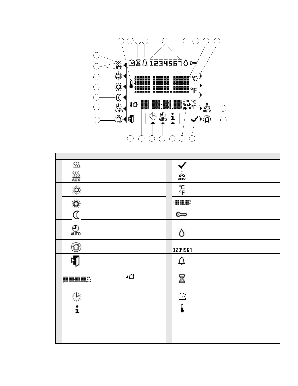
74 / 87
Siemens RDG400KN,RGD405KN Basic documentation CE1P3192en
Building Technologies 2017-02-17
232422 21
19 18 17 16
11
8
10
3
6
4
5
9
1
2
8
1412
7
15
20
13
Display
#
Symbol Description # Symbol Description
1
Heating mode 14 Confirmation of parameters
2
Heating mode,
electric heater active
15
Primary fan is active (only supported with
Synco700 primary controller)
3
Cooling mode 16
Degrees Celsius
Degrees Fahrenheit
4
Comfort 17
Digits for room temperature and setpoint
display
5
Economy 18 Button lock active
6
Auto Timer mode according to
schedule (via KNX)
19
Condensation in room (dewpoint sensor
active)
7
View a
nd
setAutoTim er
program
8
Protection mode 20
Weekday 1…7 from KNX bus
1 = Monday/7 = Sunday
9
Escape 21 Fault
10
Additional user information, like outside temperature or time of day
from KNX bus; selectable via parameters
22
Temporary timer function; visible when
operating mode is temporarily extended
(extended presence or absence)
11
Setting the time of day and the
weekday
23 Fresh air (RDG405KN)
12
Information 24 Indicates that room temperature is displ ayed
13
am/pm
ppm
am and pm: Real time clock in either
24- or 12-hour (am/pm) mode
ppm: CO2 external sensor value
(RDG405KN)
RDG400KN
RDG405KN
Page 75
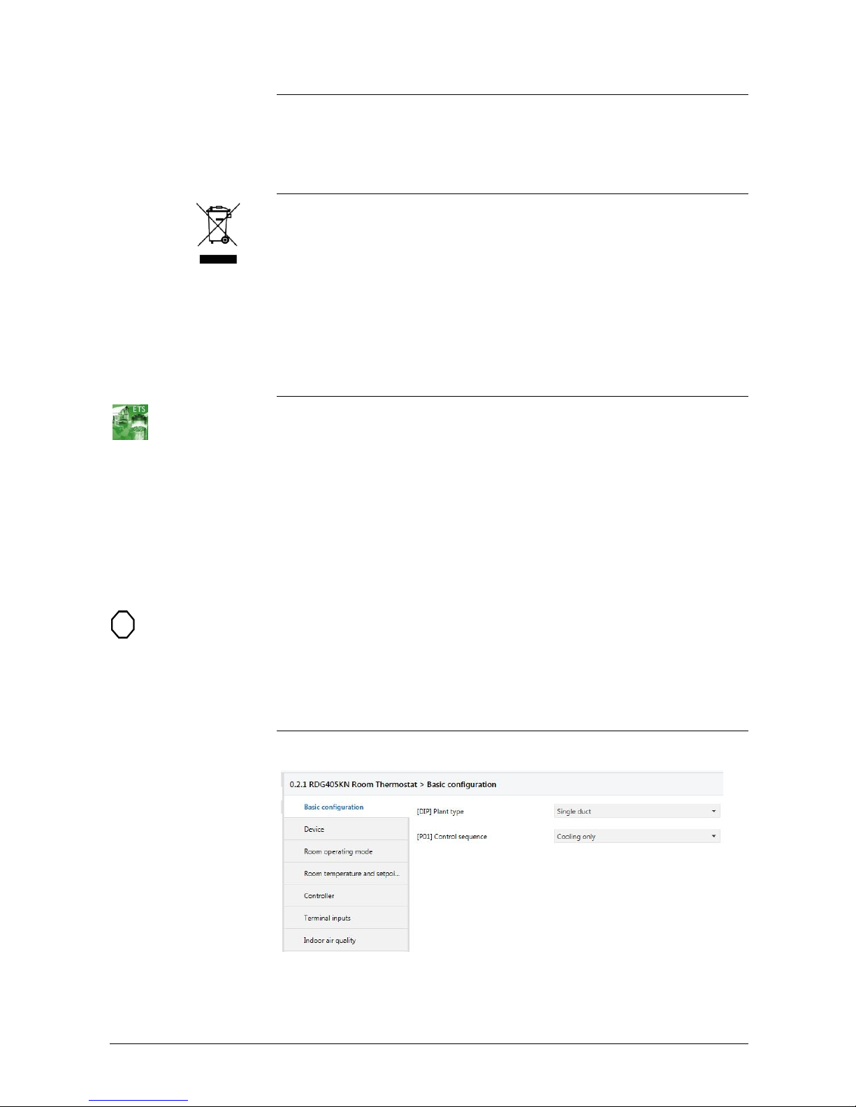
75 / 87
Siemens RDG400KN,RGD405KN Basic documentation CE1P3192en
Building Technologies 2017-02-17
4.4 Remote operation
The RDG.. room thermostats can be operated from a remote location using an
OZW772/OZW775 web server or the ACS tool.
4.5 Disposal
In terms of disposal, the room thermostats are classified as electronic scrap
conforming to the European Directive 2012/19/EU and must not be disposed of
as domestic waste.
∂ Dispose of the device via the channels provided for this purpose
∂ Comply with all local and currently applicable laws and regulations
5. Supported KNX tools
5.1 ETS
ETS is an engineering tool used to fully commission the RDG4..KNX room
thermostats.
ETS can implement the following functions:
– Defining and downloading the physical address
– Defining and downloading the application (plant type, control sequence)
– Setting up and downloading the thermostat's control parameters
– Setting up and downloading group addresses
This Basic Documentation does not describe how to operate the ETS tool and
commission a device. Refer to the KNX Manual for more details.
Setting RDG..KNX parameters is only supported by ETS4 or higher!
To start KNX programming, press left and right button simultaneously for at least
6 seconds.
5.1.1 Parameter settings in ETS
1. Open the project in ETS and select a device.
2. Click Parameters tab, and adjust the control parameters as follows:
3. The Plant type (application), Control Sequence and other control
parameters ([Pxx] description) can be downloaded.
ETS
STOP
Note
Addressing mode
Page 76

76 / 87
Siemens RDG400KN,RGD405KN Basic documentation CE1P3192en
Building Technologies 2017-02-17
ETS 4 or higher version is used to download the application and parameters
IAQ control (RDG405KN only)
1. Select if the CO2 (or VOC) sensor is to transmit (DC input) or receive
from another KNX device.
2. Set the setpoint and the P-band (Xp)
Object 44 can be used to transmit or receive the IAQ value.
5.2 ACS790
With the ACS790 tool, the RDG..KNX room thermostats can be commissioned
(physical address, application, parameters). They can be operated or monitored
via bus during normal operation.
This Basic Documentation not describe how the physical address is defined.
Also, it only gives a brief overview of the main functionality of the ACS tool.
For more information, refer to ACS online help.
Setting RDG..KNX parameters is only supported by ACS version 5.11 or
higher!
5.2.1 Parameter settings in ACS
In the ACS tool, select Plant, then Open to open the plant.
To start the parameter settings, select Applications, then Parameter
settings…:
Notes
ACS
STOP
Note
Page 77

77 / 87
Siemens RDG400KN,RGD405KN Basic documentation CE1P3192en
Building Technologies 2017-02-17
The application and control parameters can be adjusted and downloaded.
Column Line no. contains the parameter number as shown in the parameter
table (see section 3.11).
5.2.2 Operation and monitoring with ACS
In the ACS tool, select Plant, then Open to open the plant.
To start monitoring and operation, select Applications, then Plant operation –
Standard popcard
ACS
Page 78

78 / 87
Siemens RDG400KN,RGD405KN Basic documentation CE1P3192en
Building Technologies 2017-02-17
The ACS tool supports parameter settings even during normal operation.
To change a control parameter, select Applications, then Plant operation.
∂ Make sure you have logged on with sufficient access right
∂ Only control parameter can be changed, no application!
Parameter settings
in ACS
Notes
Page 79

79 / 87
Siemens RDG400KN,RGD405KN Basic documentation CE1P3192en
Building Technologies 2017-02-17
The ACS tool offers plant diagrams for easy monitoring and operation of the
thermostat. To start this application, select Standard diagram.
The ACS tool provides standard plant diagrams for RDG..KNX room
thermostats, which depend on the configuration as follows:
Plant diagram in
ACS
Page 80
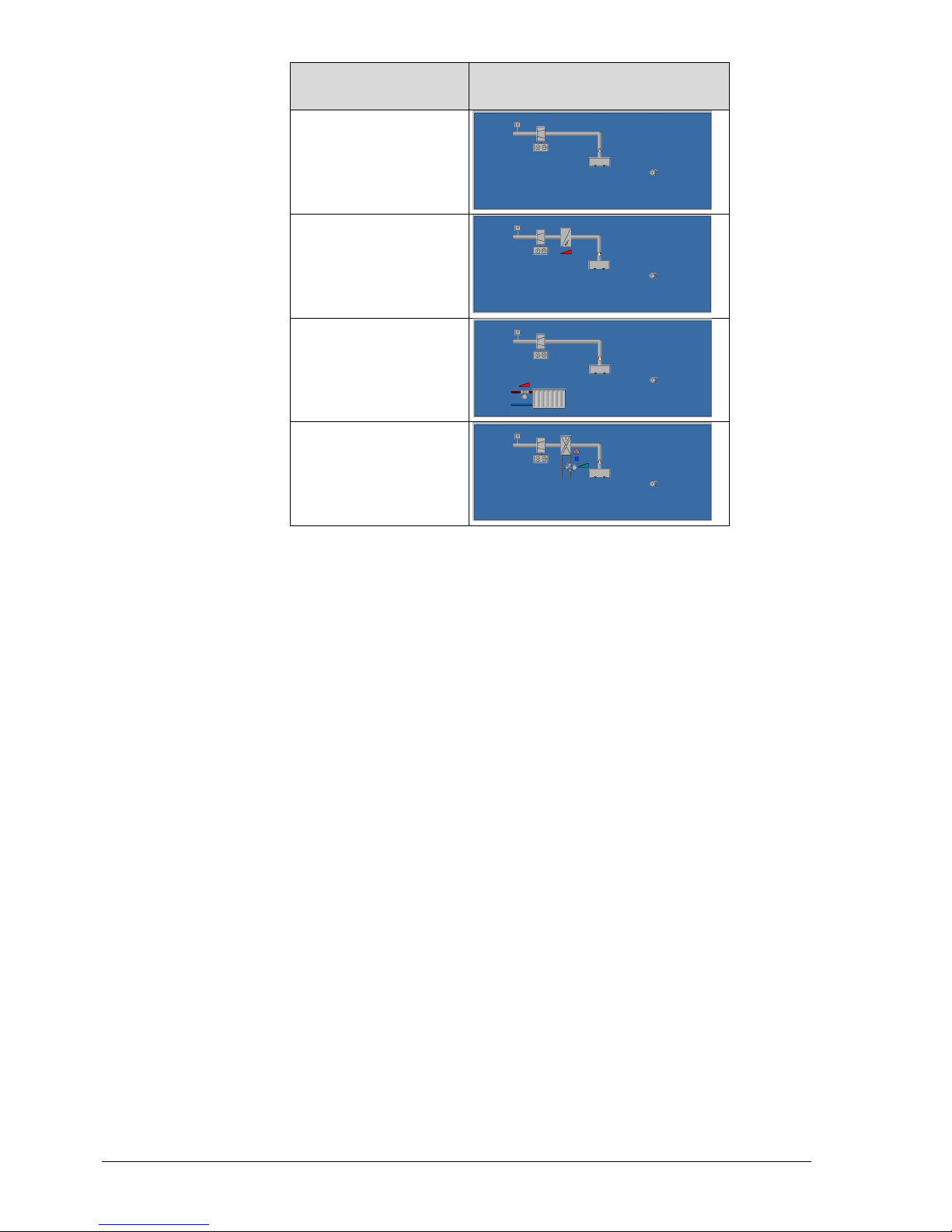
80 / 87
Siemens RDG400KN,RGD405KN Basic documentation CE1P3192en
Building Technologies 2017-02-17
Plant type
Application
Single-duct
Single-duct with electric
heater
Single-duct with radiator
Single-duct with heating/
cooling coil
Page 81
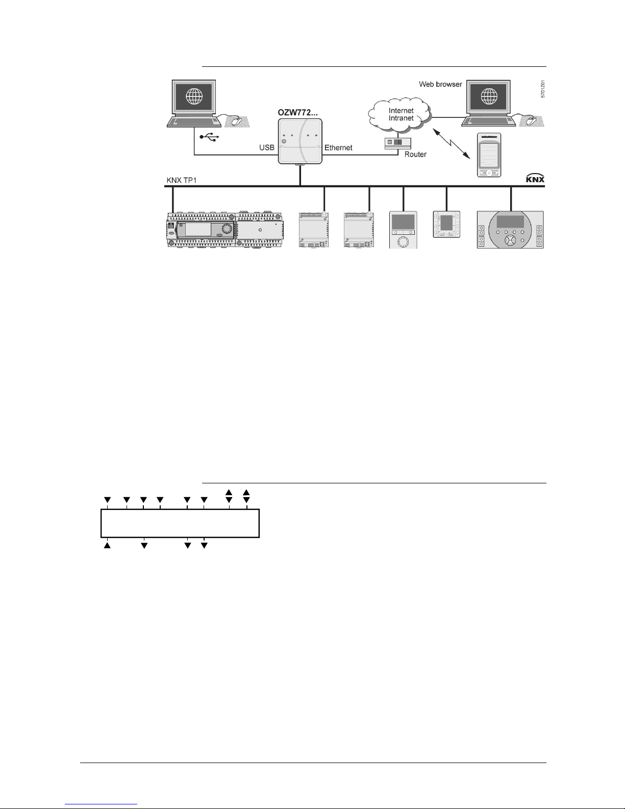
81 / 87
Siemens RDG400KN,RGD405KN Basic documentation CE1P3192en
Building Technologies 2017-02-17
5.2.3 Operation and monitoring with OZW772
.
The OZW772 web server enables users to operate a Synco HVAC system from
a remote location – via PC or from a smartphone via the web. A start page
shows the most important data points. A combination of menu/path navigation
enables users to access all data points quickly and straightforwardly. The entire
installation can be visualized in the form of plant diagrams. Alarm and state
messages can be forwarded to different message receivers, such as e-mail,
SMS, etc.
For details, refer to Commissioning Instructions CE1C5701.
6. Connection
6.1 Connection terminals
SELV
G X1M
G0
Y1
U1
3192 A01
CE+ CE
-
D1 GND
Y2Y10
G, G0 Operating voltage AC 24 V
Y10-G0 Control output for DC 0…10 V actuator
Y1-G, Y2-G Control outputs for 2-position, PWM or 3-position
actuators
X1 Multifunctional input for temperature sensor (e.g.
QAH11.1) or potential-free switch
Factory setting: External temperature sensor
(function can be selected via P38)
M Measuring neutral for sensors and switches
U1 DC 0…10 V input for actual air damper position
DC 0…10 V input for CO2 sensor (0…2000 ppm)
(RDG405KN)
(Note: G0 is the measuring neutral for U1!)
D1-GND Multifunctional input for potential-free switch.
Factory setting: Operating mode switchover contact
(function can be selected via P42)
CE+ KNX data +
CE- KNX data –
Page 82

82 / 87
Siemens RDG400KN,RGD405KN Basic documentation CE1P3192en
Building Technologies 2017-02-17
6.2 Connection diagrams
Application
N1 Room thermostat RDG4..KN
V1 Damper actuator or VAV compact controller:
DC 0…10 V or 3-position,
VAV compact controller KNX
V2 Electric heater, radiator
or heating/cooling valve:
DC 0…10 V, 2-position, PWM or 3-position
S1 Switch (keycard, window contact, etc.)
U1 DC 0…10 V input feedback signal for current
air damper position
DC 0…10 V input for CO
2
/VOC sensor
(0…2000 ppm) (RDG405KN)
S3 Switch at SELV input
(keycard, window contact)
B1 Temperature sensor (return air temperature,
external room temperature, changeover
sensor, etc.)
B2 CO2 sensor (0…2000 ppm) (RDG405KN)
CE+ KNX data +
CE- KNX data –
Single-duct
Single-duct with
electric heater,
radiator or
heating/cooling
valve
7. Mechanical design
7.1 General
The room thermostat consists of 2 parts:
∂ Plastic housing with electronics, operating elements and room temperature
sensor
∂ Mounting plate with the screw terminals
The housing engages in the mounting plate and is secured with 2 screws.
4. Operating mode selector/Esc
For operation, refer to section 4.3.
2
1
3
Page 83
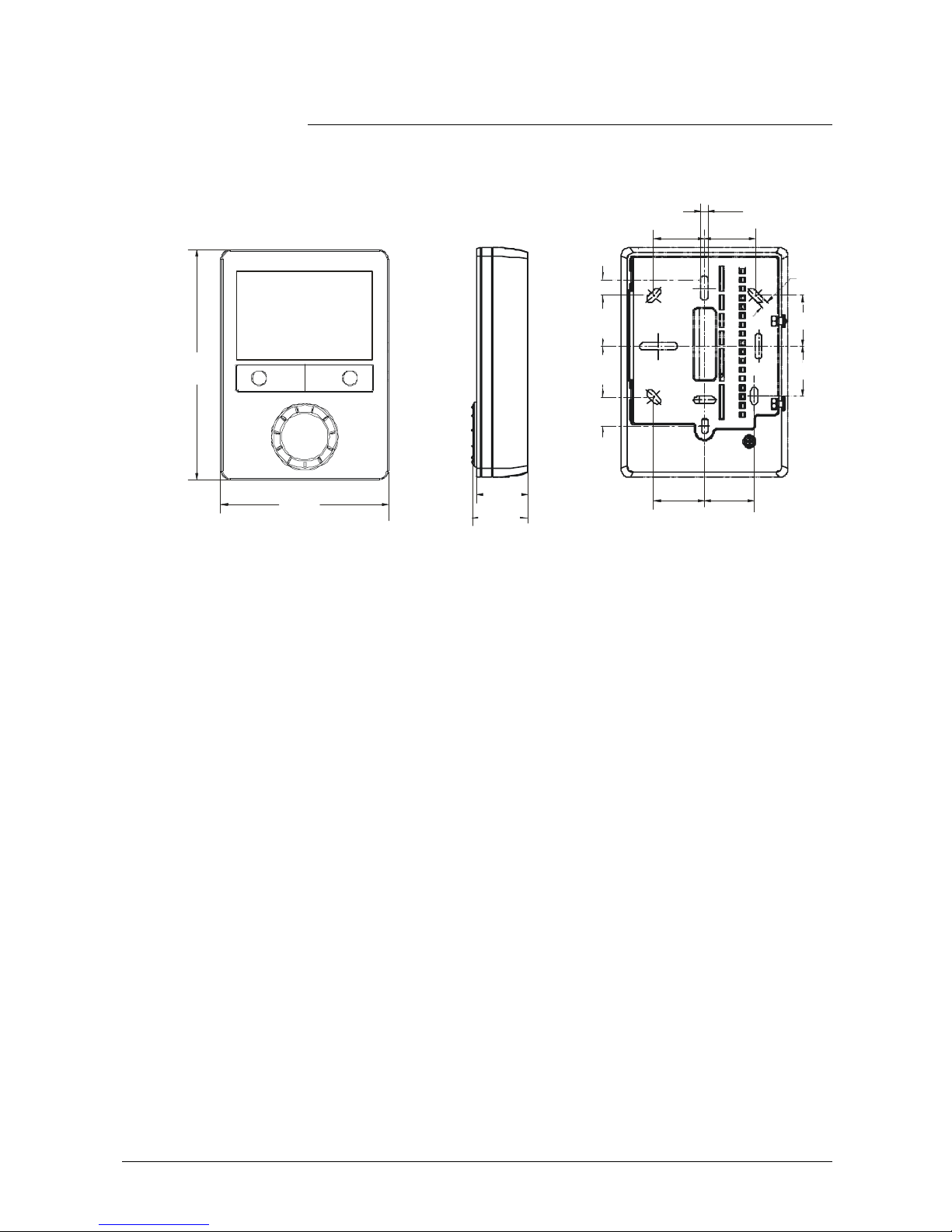
83 / 87
Siemens RDG400KN,RGD405KN Basic documentation CE1P3192en
Building Technologies 2017-02-17
7.2 Dimensions
Dimensions in mm
128.0
93.0
28.2
27.8
28.5
16.0
9.0
28.3
28.3
27.7
28.3
4.0
4.0
30.8
28.3
28.3
Page 84
84 / 87
Siemens RDG400KN,RGD405KN Basic documentation CE1P3192en
Building Technologies 2017-02-17
8. Technical data
Operating voltage SELV AC 24 V °20%
Rated voltage AC 24 V
Frequency 50/60 Hz
Power consumption Max. 2 VA/1 W
No
internal fuse!
In all cases, external preliminary protection with
a circuit breaker max. C 10 A is required.
Control output Y10-G0
Resolution
Current
DC 0…10 V
39 mV
Max. ° 1 mA
Control output Y1, Y2-G
Rating
AC 24 V
Max. 1 A
Power limitation
3 A fast microfuse
(cannot be exchanged)
Multifunctional inputs
X1-M
Temperature sensor input
Type
Temperature range
Cable length
Digital input
Operating action
Contact sensing
Parallel connection of several
thermostats for one switch
U1-G0
Input for actual air damper position
feedback
damper position 0%(fully closed)
100% (fully open)
Input for external CO2/VOC sensor
(RDG405KN)
D1-GND
Operating action
Contact sensing
Parallel connection of several
thermostats for one switch
QAH11.1 (NTC)
0...49 °C (32…120 ˚F)
Max. 80 m
Selectable (NO/NC)
DC 0…5 V, max. 5 mA
Max. 20 thermostats per
switch. Do not mix with D1!
DC 0…10 V, max. 0.3 mA
0…100%
DC 0…10 V, max. 0.3 mA
0… 2000 ppm
Selectable (NO/NC)
SELV DC 6…15 V, 3…6 mA
Max. 20 thermostats per
switch. Do not mix with X1!
Function of inputs
External temperature sensor, heating/cooling
changeover sensor, operating mode switchover
contact, dewpoint monitor contact, enable
electric heater contact, fault contact, monitoring
input
Selectable
X1: P38
D1: P42
Interface type KNX, TP1-64
(galvanically separated)
Bus current 20 mA
Bus topology: Refer to KNX Manual (see reference documentation)
Switching differential (adjustable)
Heating mode (P30)
Cooling mode (P31)
2 K (0.5...6 K)
1 K (0.5...6 K)
Setpoint setting and setpoint range
Comfort (P08)
21 °C (70 ˚F) (5…40 °C) (41…104
Power supply
Outputs
Inputs
KNX bus
Operational data
Page 85

85 / 87
Siemens RDG400KN,RGD405KN Basic documentation CE1P3192en
Building Technologies 2017-02-17
Economy (P11-P12)
Protection (P65-P66)
˚F)
15 °C/30 °C (59˚F/86 ˚F)
(OFF, 5…40 °C)
8 °C/OFF (OFF, 5…40 °C)
Multifunctional inputs X1-D1
Input X1 default value (P38)
Input D1 default value (P42)
Selectable (0...8)
1 (ext. temperature sensor,
room or return air)
3 (operating mode switchover)
Built-in room temperature sensor
Measuring range
Accuracy at 25 °C (after calibration via P05)
Temperature calibration range
0…49 °C (32…120 ˚F)
< ± 0.5 K
± 3.0 K
Settings and display resolution
Setpoints
Current temperature value displayed
0.5 °C (33 ˚F)
0.5 °C (33 ˚F)
Operation
Climatic conditions
Temperature
Humidity
IEC 721-3-3
Class 3K5
0...50 °C (32…122 ˚F)
<95% r.h.
Transport
Climatic conditions
Temperature
Humidity
Mechanical conditions
IEC 721-3-2
Class 2K3
, 25... 60 °C (-77…140 ˚F)
<95% r.h.
Class 2M2
Storage
Climatic conditions
Temperature
Humidity
IEC 721-3-1
Class 1K3
, 25... 60 °C (-77…140 ˚F)
<95% r.h.
conformity to EMC directive
CE1T3192xx *)
RCM conformity
CE1T3192en_C1
Safety class III as per EN 60730
Pollution class Normal
Degree of protection of housing IP30 as per EN 60529
Connection terminals Solid wires or stranded wires
with
ferrules
1 x 0.4…2.5 mm
2
or 2 x 0.4…1.5 mm
2
Housing front color RAL 9003 white
Weight without/with packaging 0.237 kg/0.360 kg
Environmental conditions
Standards and directives
General
Page 86

86 / 87
Siemens RDG400KN,RGD405KN B asic documentation CE1P3192en
Building Technologies Index 2017-02-17
Index
3
3-position control signal ...................................... 47
3-position for air flow ........................................... 47
A
Absence ............................................................. 20
ACS .................................................................... 76
Addressing mode .......................................... 72, 75
Air demand ......................................................... 58
Air heating/cooling changeover ........................... 31
Applications overview ......................................... 29
Automatic heating/cooling changeover .......... 31, 33
Automatic heating/cooling changeover via bus .... 31
B
Bus - set operating modes .................................. 21
Bus - setting and adjusting setpoints ................... 27
Bus power supply ............................................... 71
Button lock .......................................................... 33
C
Cable length for sensors ..................................... 52
Changeover switch ............................................. 31
Changeover via KNX .................................... 31, 51
Commissioning ...................... 18, 27, 29, 59, 65, 71
Communication objects ................................. 53, 61
Communication objects LTE ................................ 64
Connecting a KNX tool ........................................ 66
Control output VAV .............................................. 58
Control outputs configuration .............................. 50
Control outputs overview ..................................... 47
Control parameters ............................................. 65
Control sequences .............................................. 33
Cooling demand.................................................. 58
Cooling sequence ............................................... 33
D
DC 0…10 V control signal ................................... 47
DC 0…10 V for air flow ....................................... 47
DC 0…10 V for electric heaters ........................... 48
Desigo ................................................................ 10
Dewpoint monitoring ..................................... 32, 51
Digital input ......................................................... 51
DIP switches ...................................... 29, 47, 50, 71
Disposal ............................................................. 75
Download via tool ............................................... 66
E
Effect of Protection via time schedule .................. 19
Electric heater ..................................................... 38
Enable/disable electric heater ........................ 38, 52
Expert level parameters .......................................65
Extension of presence/absence ...........................20
External sensors..................................................46
External/return air temperature ...................... 51, 53
External/return air temperature sensor .................32
Extract air ............................................................30
F
Fan (primary)........................................... 38, 52, 58
Fan overrun time .................................................38
Fault ....................................................................52
Fault on KNX .......................................................59
Fault, handling .....................................................53
Floor temperature limitation function ....................32
G
Geographical zone ..............................................55
H
Heartbeat ............................................................57
Heating demand ..................................................58
Heating sequence ...............................................33
Heating/cooling changeover ................................51
I
IAQ .....................................................................14
Integral action time ..............................................13
Integration via KNX .............................................. 9
K
KNX addressing ..................................................72
KNX bus power supply ........................................71
KNX functions ...................................................... 9
KNX LTE-Mode ...................................................53
KNX overview.................................................. 6, 53
KNX parametersl .................................................75
KNX serial number ..............................................72
KNX S-Mode .......................................................53
L
LTE-Mode ...........................................................53
M
Manually select heating or cooling sequence .......33
Monitoring with ACS ............................................77
Monitoring with OZW772 .....................................81
Mounting and installation .....................................70
Multifunctional inputs ...........................................51
Page 87

87 / 87
Siemens RDG400KN,RGD405KN B asic documentation CE1P3192en
Building Technologies Index 2017-02-17
O
On/Off control signal ........................................... 47
Operating mode
Priority intervention .......................................... 18
Operating mode - setting via bus ......................... 21
Operating mode button ....................................... 19
Operating mode switchover ................................. 51
Operation with ACS............................................. 77
Operation with OZW772 ...................................... 81
OZW772 ............................................................. 81
P
Parallel connection of switches ........................... 52
Parameter setting ............................................... 65
Parameter setting via tool.................................... 66
Parameter settings in ACS ............................ 76, 78
Parameter settings in ETS .................................. 75
Precomfort .......................................................... 19
Presence ............................................................ 20
Presence detector ............................................... 20
Primary fan ............................................. 38, 52, 58
Proportional band ............................................... 13
Protection mode/standby .................................... 17
PWM .................................................................. 47
PWM for electric heaters ..................................... 49
R
Radiator .............................................................. 41
Remote heating/cooling changeover ................... 31
Remote operation ............................................... 81
Reset parameters ............................................... 65
S
Sensor input .................................................. 51, 53
Setpoint Comfort mode ....................................... 45
Setpoint Economy mode ..................................... 45
Setpoint limitation ............................................... 25
Setpoint Protection mode ................................... 45
Setpoints - setting via bus ................................... 27
Setpoints and sequences ................................... 45
S-Mode .............................................................. 53
Standby/Protection mode ................................... 17
Supply air temperature ....................................... 31
Supply and extract air ......................................... 30
Switching differential ........................................... 13
Synchronization ............................................. 47, 49
Synco 700, Synco living ........................................ 9
T
Temperature out of range ................................... 53
Temporary setpoint ............................................. 25
Time of day via KNX ........................................... 14
Time schedule change mode .............................. 19
Tool - Parameter setting and download ............... 66
V
VAV changeover ................................................. 31
VAV changeover via bus ..................................... 33
W
Window state ........................................... 17, 18, 51
Siemens Switzerland Ltd.
Building Tec hnologies Division
International Headquarters
Gubelstrasse 22
CH-6301 Zug
Tel. +41 41-724 24 24
www.buildingtechnologies.siemens.c om
© 2010 - 2017 Siemens Switzerland Ltd
.
Subject to change
 Loading...