

Page 1
N3181en
May 28. 2009
Building Technologies
3
181
RDG100 / RDG110
RDG140 / RDG160 RDG100T
Room thermostats with LCD
for wall mounting RDG1…
for fan coil unit applications
for universal applications
for use with compressors in dx type equipment
• RDG100...: Operating voltage AC 230 V, ON/OFF, 3-position or PWM control
outputs
• RDG110: Operating voltage AC 230 V, ON/OFF relay (SPDT) outputs
• RDG140 / RDG160: Operating voltage AC 24 V, DC 0…10 V control outputs
• Operating modes: Comfort, Energy Saving and Protection
• Automatic or manual fan speed
• Output for 1-speed, 3-speed or ECM fan DC 0...10 V (RDG160)
• 3 multifunctional inputs for keycard contact, external sensor, etc.
• Automatic or manual heating / cooling changeover
• Adjustable commissioning and control parameters
• Minimum and maximum setpoint limitation
• Backlit display
Additional features of RDG100T:
• Infrared remote control receiver
• Auto Timer mode with 8 programmable timers
Page 2

2/12
Siemens RDG1... room thermostats N3181en
Building Technologies May 28. 2009
Use
The RDG1… room thermostats are designed for use with the following types of system:
Fan coil units via ON/OFF or modulating control outputs:
• 2-pipe system
• 2-pipe system with electrical heater
• 2-pipe system and radiator / floor heating
• 4-pipe system
• 4-pipe system with electrical heater
• 2-stage heating or cooling system
Chilled / heated ceilings (or radiators) via ON/OFF or modulating control
outputs:
• Chilled / heated ceiling
• Chilled / heated ceiling with electrical heater
• Chilled / heated ceiling and radiator / floor heating
• Chilled / heated ceiling, 2-stage cooling or heating
Heat pumps with dx type equipment:
• 1-stage compressor for heating or cooling
• 1-stage compressor for heating or cooling with electri cal he ater
• 1-stage compressor for heating or cooling and radiat or / floor heating
• 1-stage compressor for heating and cooling with reversing valve
• 2-stage compressor for heating or cooling
Functions
• Room temperature control via built-in temperature sensor or external room
temperature / return air temperature sensor
• Automatic or manual changeover between heating and cooling mode
• Selection of applications via DIP switches
• Selection of operating mode via operating mode button on the thermostat
• 1- or 3-speed or DC 0…10 V fan control (automatic or manual)
• Display of current room temperature or setpoint in °C and/or °F
• Minimum and maximum setpoint limitation
• Button lock (automatic or manual)
• 3 multifunctional inputs, freely selectable for:
– Operating mode switchover contact (keycard, window contact, etc.)
– Changeover sensor for automatic heating / cooling mode
– External room temperature or return air temperature
– Dewpoint sensor
– Electrical heater enable
– Faults
• Advanced fan control function, i.e. fan kick, fan start, selectable fan operation
depending on heating / cooling mode, fan start delay in systems with ON/OFF
control
• Purge function in conjunction with 2-port valve in systems with automatic heating /
cooling changeover
• Reminder to clean fan filters
• Floor heating temperature limitation
• Reload factory settings for commissioning and control parameters
• 7-day time program: 8 programmable timers to switch over between Comfort and
Energy Saving mode (RDG100T)
• Infrared remote control (RDG100T)
Page 3
3/12
Siemens RDG1… room thermostats N3181en
Building Technologies May 28. 2009
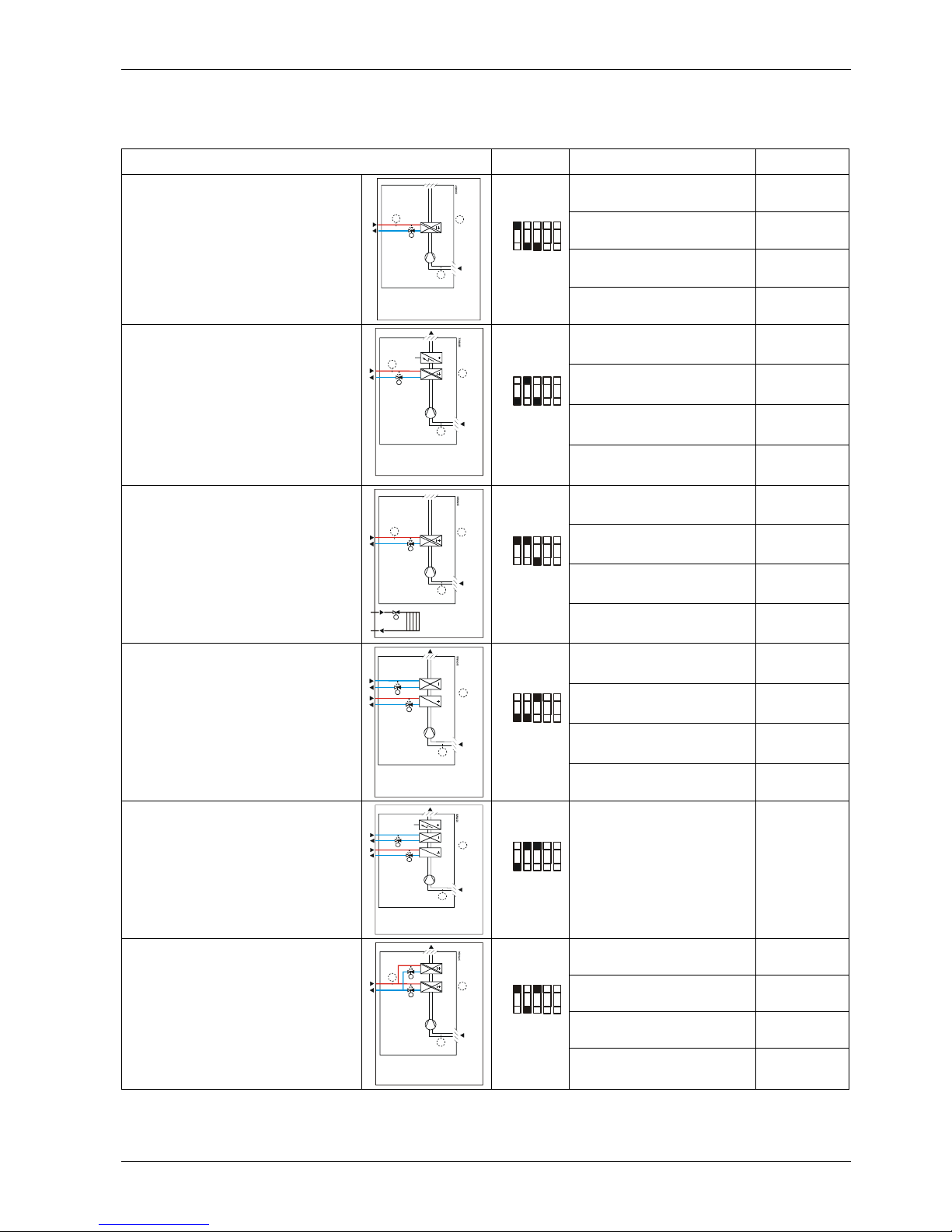
Applications
The room thermostats support the following applications, which can be configured via
DIP switches at the rear of the unit. Depending on the thermostat type, ON/OFF or
modulating control outputs are available.
Application
DIP switch
Control output Product no.
ON/OFF, PWM, 3-position RDG100…
ON/OFF (SPDT) RDG110
DC 0…10 V
RDG140
Heating or cooling
• 2-pipe fan coil unit
• Chilled / heated ceiling
• 1-stage compressor
1)
(B1)
M1
Y1
T
B2
T
T
(B1)
1 2 3 4 5
ON
OFF
DC 0…10 V
2)
RDG160
ON/OFF, PWM, 3-position RDG100..
ON/OFF (SPDT) RDG110
DC 0…10 V
Note: Modulating el. heater
RDG140
Heating or cooling with auxiliary
heater
• 2-pipe fan coil unit with el. heater
• Chilled / heated ceiling and el.
heater
• 1-stage compressor
and el. heater
1)
Y1
M1
T
B2
E1
T
(B1)
T
(B1)
1 2 3 4 5
ON
OFF
DC 0…10 V
2)
Note: Modulating el. heater
RDG160
ON/OFF, PWM, 3-position RDG100…
ON/OFF (SPDT) RDG110
DC 0…10 V
RDG140
Heating or cooling and radiator /
floor heating
• 2-pipe fan coil unit and radiator
• Chilled / heated ceiling and
radiator
(B1)
M1
Y1
T
B2
T
T
(B1)
YR
1 2 3 4 5
ON
OFF
DC 0…10 V
2) RDG160
ON/OFF, PWM, 3-position RDG100…
ON/OFF (SPDT) RDG110
DC 0…10 V
RDG140
Heating and cooling
• 4-pipe fan coil unit
• Chilled ceiling and radiat or
• 1-stage compressor
1)
• 1-stage compressor with reversing
valve
1)
T
Y2
Y1
M1
(B1)
T
(B1)
1 2 3 4 5
ON
OFF
DC 0…10 V
2)
RDG160
Heating and cooling with auxiliary
heater
• 4-pipe fan coil unit with el. heater
T
Y2
Y1
M1
(B1)
T
(B1)
YE
1 2 3 4 5
ON
OFF
ON/OFF, PWM, 3-position RDG100…
ON/OFF, PWM, 3-position RDG100...
ON/OFF (SPDT) RDG110
DC 0…10 V RDG140
2-stage heating or cooling
• 2-stage fan coil unit
• 2-stage chilled / heated ceiling
• 2-stage compressor
1)
Y1
M1
T
B2
T
(B1)
T
(B1)
Y2
1 2 3 4 5
ON
OFF
DC 0…10 V
2)
RDG160
1) Heat pump application covered by RDG110
2) With ECM fan control DC 0…10 V
Page 4
4/12
Siemens RDG1... room thermostats N3181en
Building Technologies May 28. 2009
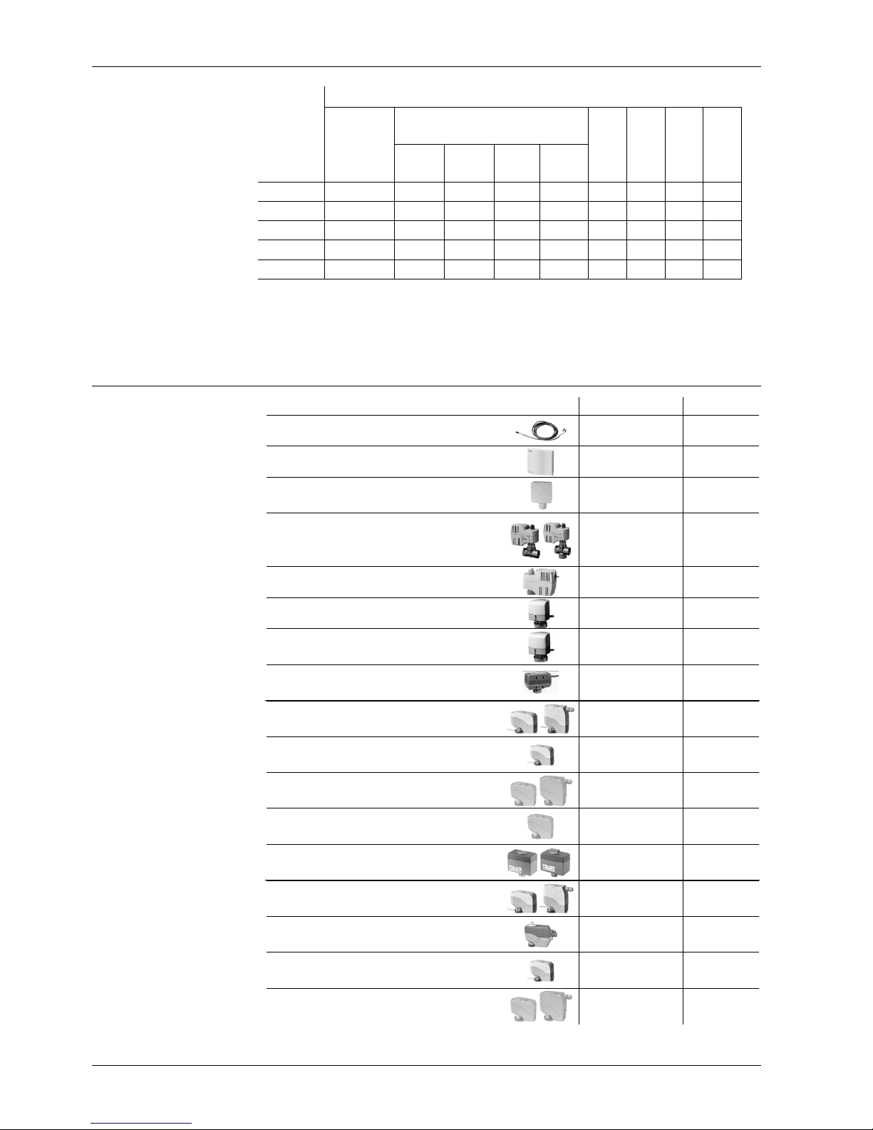
Type summary
Equipment combinations
Type of unit Type reference Data Sheet
Cable temperature sensor
QAH11.1
1840
Room temperature sensor
QAA32
1747
Condensation detector / Supply unit
QXA2000 /
AQX2000
1542
Electromotoric ON/OFF valve and
actuator
(only available in AP, UAE, SA and IN)
MVI…/MXI…
4867
Electromotoric ON/OFF actuator
SFA21...
4863
Thermal actuator (for radiator valve)
STA21...
4877
Thermal actuator
(for small valves 2.5 mm)
STP21...
4878
Zone valve actuators
(only available in AP, UAE, SA and IN)
SUA…
4832
Electrical actuator, 3-position
(for radiator valve)
SSA31...
4893
Electrical actuator, 3-position
(for small valve 2,5 mm)
SSP31…
4864
Electrical actuator, 3-position
(for small valve 5,5 mm)
SSB31...
4891
Electrical actuator, 3-position
(for Combi-valve VPI45)
SSD31...
4861
Electromotoric actuator, 3-position
(for valves 5.5 mm)
SQS35…
4573
Electrical actuator, DC 0..10 V
(for radiator valve)
SSA61...
4893
Electrical actuator, DC 0..10 V
(for 2 and 3 port valves / V…P45)
SSC61…
4895
Electrical actuator, DC 0..10 V
(for small valve 2,5 mm)
SSP61…
4864
Electrical actuator, DC 0..10 V
(for small valves 5.5 mm)
SSB61...
4891
Features
Number of control outputs
Product
no.
Operating
voltage
ON/OFF PWM 3-pos.
DC
0..10 V
Time
program
Backlit LCD
Infrared
receiver
1)
ECM fan
2)
RDG100
AC 230 V
3
3)
23) 23)
9
RDG100T
AC 230 V
3
3)
23) 23)
9 9 9
RDG110
AC 230 V
24)
9
RDG140
AC 24 V
2 9
RDG160
AC 24 V
2 9
9
1) Infrared remote control must be ordered as a separate item
2) ECM fan output DC 0…10 V
3) ON/OFF, PWM or 3-position (triac outputs)
4) Relay output (SPDT)
ON / OFF actuators
3-position actuators
DC 0…10 V actuators
Page 5

5/12
Siemens RDG1… room thermostats N3181en
Building Technologies May 28. 2009
Electrical actuator, DC 0..10 V
(for Combi-valve VPI45)
SSD61...
4861
Electromotoric actuator, DC 0..10 V
(for valves 5.5 mm)
SQS65…
4573
Thermal actuator, DC 0..10 V
(for small valves and radiator valves)
STS61
4880
Accessories
Description Product no. Data Sheet
Changeover mounting kit (50 pcs / package) ARG86.3 1840
Adapter plate 120 x 120 mm for 4“ x 4“ conduit boxes ARG70
Adapter plate 112 x 130 mm for surface wiring ARG70.2
Ordering
When ordering, please indicate product no. and description:
E.g. RDG100 room thermostat
Order the IRA211 infrared remote control separately.
Order valve actuators separately.
Mechanical design
The room thermostat consists of 2 parts:
• Plastic housing which accommodates the electronics, the operating elements and the
room temperature sensor
• Mounting plate with the screw terminals
The housing engages in the mounting plate and is secured with 2 screws.
1. Operating mode selector / Esc
2. Fan mode selector / Ok
3. Rotary knob for setpoint and parameter
adjustment
1.
Operating mode selector / Esc
2. Button to enter the time and to set the
timers
3. Fan mode selector / Ok
4. Rotary knob for setpoint and parameter
adjustment
Operation and settings
RDG…
RDG100T
1
3
2
1
3
4
Page 6

6/12
Siemens RDG1... room thermostats N3181en
Building Technologies May 28. 2009
1
2
4
5
6
7
8
8
9
10
11
12 13
14
15
16
17
1819
20
2123
3
22
24
# Symbol Description # Symbol Description
1
Heating mode
14
Automatic fan
2
Heating mode
auxiliary heater on (2nd stage)
15
Manual fan
3
Cooling mode
Fan speed 1
4
Comfort mode
Fan speed 2
5
Energy Saving mode
16
Fan speed
Fan speed 3
6
Auto Timer mode
7
View and set Auto Timer program
17
Degrees Celsius
Degrees Fahrenheit
8
Protection 18 Digits for room temperature and setpoint display
9
Escape
19
Button lock
10
Digits for time, room temperature,
setpoint, etc.
20
Condensation in room (dewpoint sensor active)
11
Setting the time of day and the
weekday
21 Weekday 1…7: 1 = Monday / 7 = Sunday
22
Fault
12
Morning: 12-hour format
Afternoon: 12-hour format
23
Temporary timer function (visible when
operating mode is temporarily extended due to
prolonged presence or absence)
13
Confirmation of parameters
24
Indicates that room temperature is displayed
Display
Page 7

7/12
Siemens RDG1… room thermostats N3181en
Building Technologies May 28. 2009
Mounting and installation
Do not mount on a wall in niches or bookshelves, behind curtains, above or near heat
sources, or exposed to direct solar radiation. Mount about 1.5 m above the floor.
• The room thermostat must be mounted in a clean, dry indoor place and must not be
exposed to drip or splash water
See Mounting Instructions (M3181) enclosed with the thermostat.
• Comply with local regulations to wire, fuse and earth the thermostat
• Size correctly the cables to the thermostat, fan and valve actuators for AC 230 V
mains voltage
• Use only valve actuators rated for AC 230 V on RDG100… / RDG110
• The power supply line must have an external fuse or circuit breaker with a rated
current of no more than 10 A
• Isolate the cables of inputs X1-M / X2-M and D1-GND if the conduit box carries
AC 230 V mains voltage
• On the RDG100.. and RDG110, inputs X1-M and X2-M carry mains potential.
If the sensor’s cables are extended, they must be suited for mains voltage
• Inputs X1-M, X2-M or D1-GND of different units (e.g. summer / winter switch) may
be connected in parallel with an external switch. Consider overall maximum contact
sensing current for switch rating
• Disconnect power supply before removing the thermostat from the mounting plate!
Select the application and the type of control output via the DIP switches before fitting
the thermostat to the mounting plate.
After power is applied, the thermostat carries out a reset during which all LCD
segments flash, indicating that the reset was correct. After the reset, which takes about
3 seconds, the thermostat is ready for commissioning by qualified HVAC staff.
The control parameters of the thermostat can be set to ensure optimum performance of
the entire system (see Basic Documentation P3181).
• The control sequence may need to be set via parameter P01 depending on the
application. The factory setting for the 2-pipe application is “Cooling only”; and
“Heating and cooling” for the 4-pipe application
• When the thermostat is used in connection with a compressor, the minimum output
on-time (parameter P48) and off-time (parameter P49) for Y11/Y21 must be
adjusted to avoid damage to the compressor and shortening its life
• Recalibrate the temperature sensor if the room temperature displayed on the
thermostat does not match the room temperature measured. To do this, change
parameter P05
• We recommend to review the setpoints and setpoint ranges (parameters P08…P12)
and change them as needed to achieve maximum comfort and save energy
Mounting
Wiring
Commissioning
Control sequence
Compressor-based
application
Calibrate sensor
Setpoint and setpoint
range limitation
Page 8

8/12
Siemens RDG1... room thermostats N3181en
Building Technologies May 28. 2009
Disposal
The device is classified as waste electronic equipment in terms of the European Directive 2002/96/EC (WEEE) and should not be disposed of as unsorted municipal waste.
The relevant national legal rules are to be adhered to. Regarding disposal, use the
systems setup for collecting electronic waste.
Observe all local and applicable laws.
Technical data
Operating voltage AC 230 V +10/-15%
Frequency 50/60 Hz
Power consumption Max. 18 VA
Fan control Q1, Q2, Q3-N
Rating
AC 230 V
Max. 5(4) A
Control outputs
Y1, Y2, Y3, Y4-N (RDG100)
Y11-N / /Y21-N (NO) (RDG110)
AC 230 V, max. 1 A
AC 230 V, max. 5(3) A
Multifunctional inputs
X1-M / X2-M
Temperature sensor input
Type
Digital input
Operating action
Contact sensing
Insulation against mains
D1-GND
Operating action
Contact sensing
Insulation against mains
QAH11.1 (NTC)
Selectable (NO/NC)
DC 0…5 V, max. 5 mA
N/A, mains potential
Selectable (NO/NC)
SELV DC 6…15 V, 3…6 mA
3.75 kV, reinforced insulation
Function input
External temperature sensor, changeover sensor,
operating mode switchover contact, dewpoint monitor
contact, enable electrical heater contact, fault contact
Selectable
Operating voltage SELV AC 24 V ± 20%
Frequency 50/60 Hz
Power consumption Max. 2 VA
Fan control
Q1, Q2, Q3-N (RDG140)
Y50-G0 (RDG160)
AC 230 V, max. 5(4) A
SELV DC 0…10 V
Max. ± 1mA
Control outputs Y10-G0 / Y20-G0
Resolution
Current
SELV DC 0…10 V
39 mV
Max. ± 1 mA
Multifunctional inputs
X1-M / X2-M
Temperature sensor input
Type
Digital input
Operating action
Contact sensing
Insulation against mains
D1-GND
Operating action
Contact sensing
Insulation against mains
QAH11.1 (NTC)
Selectable (NO/NC)
DC 0…5 V, max. 5 mA
3.75 kV, reinforced insulation
Selectable (NO/NC)
SELV DC 6…15 V, 3…6 mA
3.75 kV, reinforced insulation
Function input: Selectable
RDG100… / RDG110
Power supply
Outputs
Inputs
RDG140 / RDG160
Power supply
Outputs
Inputs
Page 9

9/12
Siemens RDG1… room thermostats N3181en
Building Technologies May 28. 2009
External temperature sensor, changeover sensor,
operating mode switchover contact, dewpoint monitor
contact, enable electrical heater contact, fault contact
Switching differential, adjustable
Heating mode (P30)
Cooling mode (P31)
2 K (0.5…6 K)
1 K (0.5…6 K)
Setpoint setting and setpoint range
Comfort mode (P08)
Energy Saving mode (P11-P12)
Protection (P65-P66)
21 °C (5…40 °C)
15 °C/30 °C (OFF, 5…40 °C)
8 °C/OFF (OFF, 5…40 °C)
Multifunctional inputs X1 / X2 / D1
Input X1
Input X2
Input D1
Selectable
Ext. temperature sensor
(P38=1)
Changeover sensor
(P40=2)
Operating mode switchover
(P42=3)
Built-in room temperature sensor
Measuring range
Accuracy at 25 °C
Temperature calibration range
0…49 °C
< ± 0.5 K
± 3.0 K
Settings and display resolution
Setpoints
Current temperature value displayed
0.5 °C
0.5 °C
Operation
Climatic conditions
Temperature
Humidity
As per IEC 721-3-3
Class 3K5
0…50 °C
<95% r.h.
Transport
Climatic conditions
Temperature
Humidity
Mechanical conditions
As per IEC 721-3-2
Class 2K3
− 25…60 °C
<95% r.h.
Class 2M2
Storage
Climatic conditions
Temperature
Humidity
As per IEC 721-3-1
Class 1K3
− 25…60 °C
<95% r.h.
conformity
EMC directive
Low-voltage directive
2004/108/EC
2006/95/EC
N474
C-tick conformity to
EMC emission standard
AS/NSZ 4251.1:1999
Reduction of hazardous substances
2002/95/EC
Product standards
Automatic electrical controls for household and
similar use
Special requirements for temperature-dependent
controls
Electronic control type
As per EN 60730–1
As per EN 60730–2-9
2.B (micro-disconnection on
operation)
Operational data, all
types
Environmental
conditions
Standards
Page 10

10/12
Siemens RDG1... room thermostats N3181en
Building Technologies May 28. 2009
Electromagnetic compatibility
Emissions
Immunity
As per IEC/EN 61000-6-3
As per IEC/EN 61000-6-2
Safety class
RDG100… / RDG110, RDG140
RDG160
II as per EN 60730
III as per EN 60730
Pollution class Normal
Degree of protection of housing IP30 to EN 60529
Connection terminals Solid wires or prepared
stranded wires
1 x 0.4…2.5 mm
2
or 2 x 0.4…1.5 mm
2
Housing front color RAL 9003 white
Weight RDG100… / RDG110 / RDG140
RDG160
0.30 kg
0.25 kg
Connection terminals
RDG100..
L X1 M X2 D1 GND
N Q1 Q2 Q3 Y1 Y2 Y 3 Y4
3181G01
SELV
RDG110
SELV
L X1 M X2 D1 GND
N Q1 Q2 Q3 Y11 Y12 Y21 Y22
3181G01
RDG140
G X1 M X2 D1 GND
G0 L Q1 Q2 Q3
Y10
Y20
3181G01
SELV
RDG160
G X1 M X2 D1 GND
G0 Y50
Y10
Y20
3181G01
SELV
L, N Operating voltage AC 230 V
G, G0 Operating voltage AC 24 V
X1, X2 Multifunctional input for temperature sensor
(e.g. QAH11.1) or potential-free switch
Factory setting:
- X1 = external room temperature sensor
- X2 = sensor or switch for automatic heating / cooling
changeover.
M Measuring neutral for sensor and switch
D1, GND Multifunctional input for potential-free switch
Factory setting: Operating mode switchover contact
Q1 Control output fan speed “low” AC 230 V
Q2 Control output fan speed “medium” AC 230 V
Q3 Control output fan speed “high” AC 230 V
Y50 Control output fan speed DC 0…10 V
Y1…Y4 Control output “Valve” AC 230 V (NO, for normally
closed valves), output fo r electrical heater via external
relay
Y11, Y21 Control output “Valve” AC 230 V (NO, for normally
closed valves), output for compressor or electrical
heater
Y12, Y22 Control output “Valve” AC 230 V (NC, for normally
open valves)
Y10, Y20 Control output for DC 0…10 V actuator
General
Page 11

11/12
Siemens RDG1… room thermostats N3181en
Building Technologies May 28. 2009
Connection diagrams
RDG100…
1- or 3-speed fan
RDG110
1- or 3-speed fan
2-pipe
2-pipe
2-pipe & radiator
4-pipe
2-stage
2-pipe & radiator
4-pipe
2-stage
2-pipe
& el. heater
2-pipe
& el. heater
4-pipe
& el. heater
1- and 2-stage
compressor
Compressor
& el. heater
Compressor
& reversing
valve
RV
N1 Room thermostat RDG1…
M1 1- or 3-speed fan
V Valve actuators:
ON/OFF or PWM, 3-position, heating, cooling,
radiator, heating / cooling, 1
st
or 2nd stage
E1 Electrical heater
C1, C2 Compressor
S1, S2 Switch (keycard, window contact, etc.)
S3 Switch at SELV input (keycard, window contact)
B1, B2 Temperature sensor (return ai r temperature,
external room temperature, changeover sensor,
floor temperature limit, etc.)
RV Reversing valve
Y Relay
Page 12

12/12
Siemens RDG1... room thermostats N3181en
Building Technologies May 28. 2009
RDG140
1- or 3-speed fan
RDG160
ECM fan DC 0…10 V
2-pipe
S3
2-pipe
2-pipe &
radiator
4-pipe
2-stage
2-pipe &
radiator
4-pipe
2-stage
2-pipe
& el. heater
2-pipe
& el. heater
N1 Room thermostat RDG1…
M1 1- or 3-speed fan
M2 ECM fan DC 0…10 V
V Valve actuators DC 0…10 V:
Heating, cooling, radiator, heating / cooling,
1
st
or 2nd stage
E1 Electrical heater
S1, S2 Switch (keycard, window contact, etc.)
S3 Switch at SELV input (keycard, window contact)
B1, B2 Temperature sensor (return air temperature, external
room temperature, changeover sensor, floor temperature
limit, etc.)
YR DC 0...10 V signal converter / current valve
Dimensions
128.0
93.0
28.2
27.8
28.5
16.0
9.0
28.3
28.3
27.7
28.3
4.0
4.0
30.8
28.3
28.3
[mm]
© 2009 Siemens Switzerland Ltd. Subject to change
 Loading...