

Page 1
s
A6V
11282546
Touch Screen Flush-mount Room
with an additional HMI for
Thermostats with KNX
Communications
Under Floor Heating (UFH) control application
Variable Refrigerant Flow (VRF) commands via KNX S-mode
· Large display, touch screen with backlight
· VRF HMI: adjust setpo int, fan mode, fan speed and operating modes
· 2-position (ON/OFF) temperature control with potential free output for UFH
via build-in / external temperature sensor
· Display room temperature value (°C) and relative humidity value (% r.h.)
via a build-in temperature and humidity sensor
· One setpoint adjustment for both VRF HMI and UFH controls
· Fan auto and manual speed setting from 1 up to 7 speed
· Operating mode selection for VRF: AUTO, COOL, HEAT, FAN and DRY
· Operating mode selection for UFH: Comfort and Protection
· Economy operating mode for both VRF and UFH to save energy
· 2 mult ifunctional inputs (see details in functional descriptions)
· Adjustable contro l parameters for alternative settings
· KNX bus communications via S-mode and LTE-mode
· Integration to VRF system via S-mode and third party gateways
· Commissioning via ETS download
· Wizard function for fast commissioning via HMI
· Alarm / Error information
· AC 230 V operating voltage
· RDF880KN/NF: Mounting on recessed square 86 mm box with 60.3 mm
fixing centers and min 40 mm depth, requires additional mounting frame
to complete installation
RDF880KN/NF
A6V11282546_en--_a
2018-04-19
Building Technologies
Page 2

Use
More than just room temperature control via a connected VRF system or a UFH
system or both:
Typical applications:
· Residential apartments
· Small office or commercial buildings
· Schools / Universities
For the VRF HMI, the unit interfaces to VRF systems via a third party gateway for:
· User application selection: - UFH only or VRF only or both
· Setpoint adjustment: - maximum / minimum limitations
· Fan speed adjustment: - auto / manual speeds (up to 7 speeds)
· Operating mode selection: - AUTO, HEAT, COOL, FAN and DRY
· Economy mode: - energy saving
· Fan swing adjustment (optional): - auto swing or fix at any position (10)
· Delay off timer (optional): - allow up to 23 hours operations before off
For the control of the following pieces of heating equipment:
· Floor Heating
· Thermal valves or zone valves
· Gas or oil boilers
· Fans
· Pumps
Functions
The configuration can be done locally or remotely via one of the following:
· Local HMI & DIP switches
· Synco ACS (UFH only)
· ETS4/5 (binding S-mode objects for VRF & UFH)
· Room temperature control via a built-in or external room temperature sensor
· Calibrations for both internal temperature and relative humidity sensors
· Display of current room temperature or setpoint in °C
· Minimum and maximum limitation of room temperature setpoint
· Fan speed adjustment, auto, manual (up to 7 speeds)
· Selection of VRF operating mode:
à AUTO, HEAT, COOL, FAN and DRY
· Selection of UFH operating mode:
à Comfort and Protection
· Energy saving (Economy mode) for both VRF and UFH
· Key lock function: unlock, total lock and setpoint lock
· 2 multifunctional inputs, freely selectable for:
- External room temperature or return air temperature sensor
- Window contact
- Fault input
- Monitor input for temperature sensor or switch state
· Floor heating temperature limitation
· Display of outdoor temperature and time scheduling via KNX bus
· Reload factory settings for commissioning and control parameters
Optional: enable / disable via parameters
· Relative humidity display via a built-in humidity sensor
· Fan swing selection: auto swing or fix at any position (up to 10)
· Delay off timer: up to 23 hour operations
· Chinese text display for 4 navigation icons
2 / 24
Siemens RDF880KN … A6V11282546_en--_a
Building Technologies Touch Screen Flush- mount Room Thermostats with KNX Communications 2018-04-19
Page 3
Applications
RDF880KN/NF is designed to provide easy-to-understand HMI for any existing
VRF system installed in residential homes and apartments where Under Floor
Heating (UFH) room thermostat may be required at the same time.
RDF880KN/NF has three kinds of applications including VRF HMI or UFH or both.
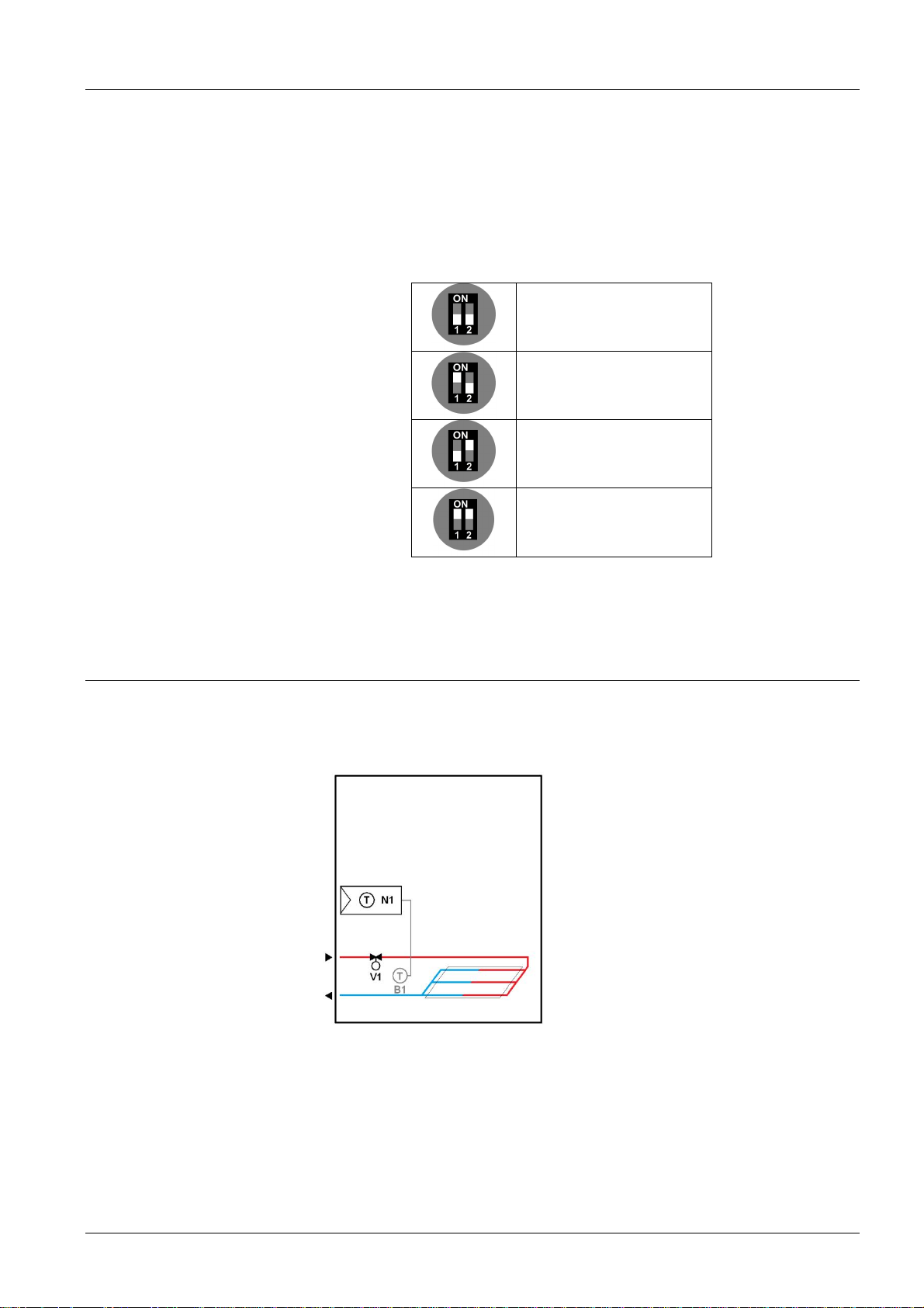
Applications are selectable via DIP switches.
Download via ETS
(All in OFF positions)
UFH only
VRF HMI only
VRF HMI and UFH
UFH Application
For selection under application mode via HMI, refer to user manual A6V11272225
for selecting applications.
For the UFH application, RDF880KN/NF provides an ON/OFF output to control
water valve to maintain a comfort level of room temperature.
Room thermostat to control the valve
for the floor heating application
3 / 24
Siemens RDF880KN … A6V11282546_en--_a
Building Technologies Touch Screen Flush- mount Room Thermostats with KNX Communications 2018-04-19
Page 4
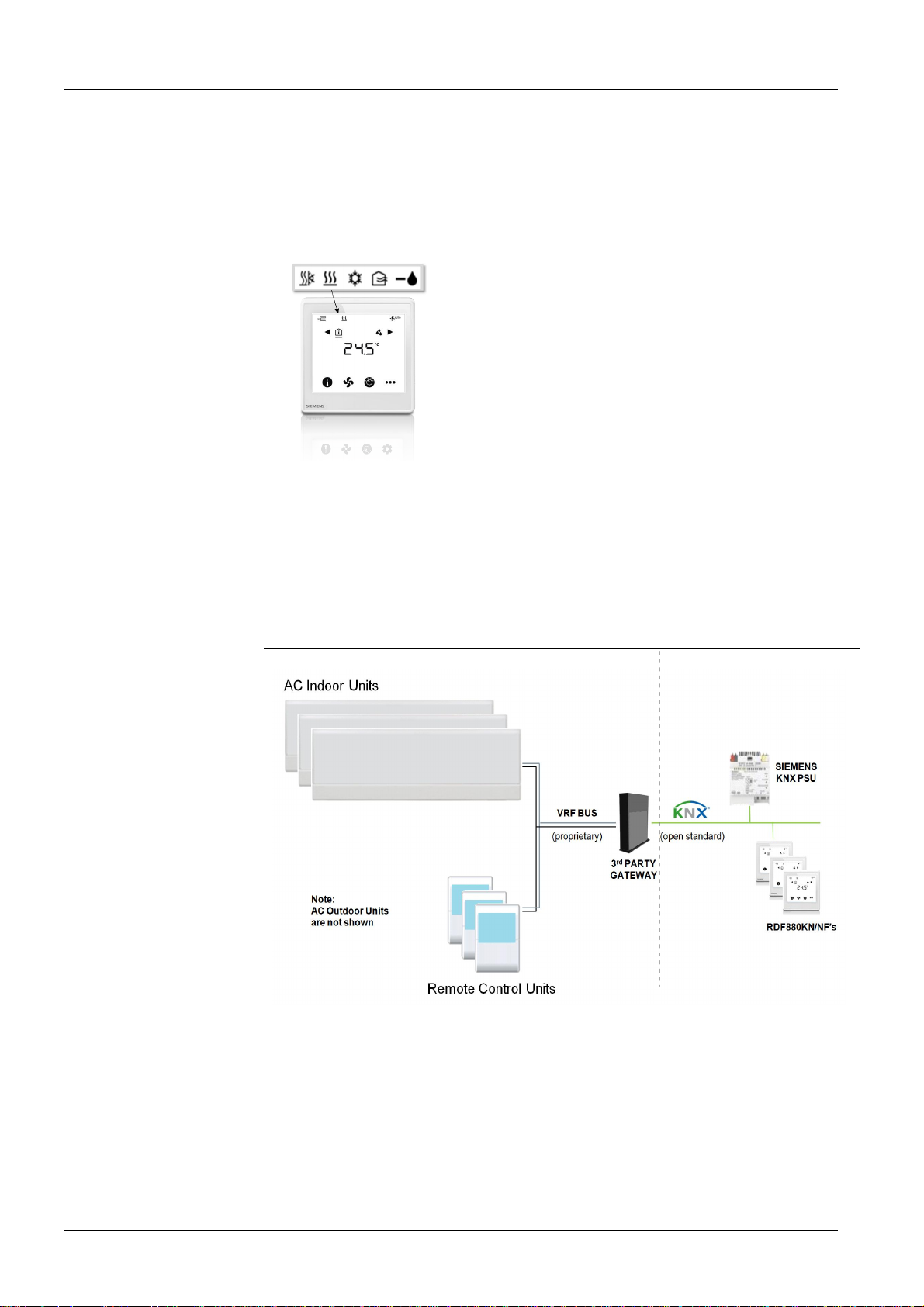
VRF Application (HMI only)
For the VRF application, RDF880KN/NF provides an easy-to-understand HMI for
adjusting frequent used operations of the VRF systems such as adjustments of
temperature setpoint, fan speed, VRF operating mode, etc.
Since all VRF brands have their own communication protocols
between the remote control unit and VRF equipments (e. g. indoor
or outdoor units), RDF880KN/NF can send all standard KNX
commands (S-mode KNX objects) via the KNX bus to a third party
KNX/VRF gateway (as a protocol converter) and then communicate
indirectly with the VRF indoor or outdoor units. Effectively, it works
similarly like a remote control unit of a VRF system.
Note that RDF880KN/NF cannot replace all functions of the remote
control unit of the VRF system but the following typical VRF
functions:
· Temperature - provide current room temperature value
- adjust temperature setpoint
· Fan - select auto or manual speed up to 7 levels
- select auto swing or fixed swing positions
· Operation - set to AUTO, HEAT, COOL, FAN and DRY
Typical VRF Systems
(Provided by 3rd Party, non-Siemens products)
Integration
via KNX Bus S-mode
4 / 24
Siemens RDF880KN … A6V11282546_en--_a
Building Technologies Touch Screen Flush- mount Room Thermostats with KNX Communications 2018-04-19
Page 5

Other Heating Applications
RDF880KN/NF is not limited to UFH applications but also for the following heating
applications such as radiators, wall hung boilers, etc.
Room thermostat to control the valve of
the radiator application
Room thermostat with direct control of a
gas-fired wall-hung boiler
Room thermostat with direct control of a
heat pump (pre-controlled by manual
mixing valve)
F1 Thermal reset limit thermostat
F2 Safety limit thermostat
M1 Circulating pump
Room thermostat with direct control of a
gas-fired floor-standing boiler
Room thermostat with direct control of
hydronic floor heating system
N1 Room thermostat
V1 2-port valve
V2 Mixing 3-port valve with
manual adjustm ent
V3 Magnetic valve
5 / 24
Siemens RDF880KN … A6V11282546_en--_a
Building Technologies Touch Screen Flush- mount Room Thermostats with KNX Communications 2018-04-19
Page 6
Type summary
2)
Product no. Stock no .
Operati ng
voltage
RDF880KN/NF2) S55770-T398 AC 230 V --
1)
ON/OFF output with potential free input from AC 24…230 V
2)
Mounting frames are not included and must be ordered separately. (See
“Accessories”)
Ordering
· When ordering, indicate product number, SSN and name.
e.g. RDF880KN/NF (S55770-T398) heating thermostat with VRF HMI
· A mounting frame or multi-frame must be ordered for RDF880KN/NF installation.
(See “Accessories”)
· Order valve actuators separately.
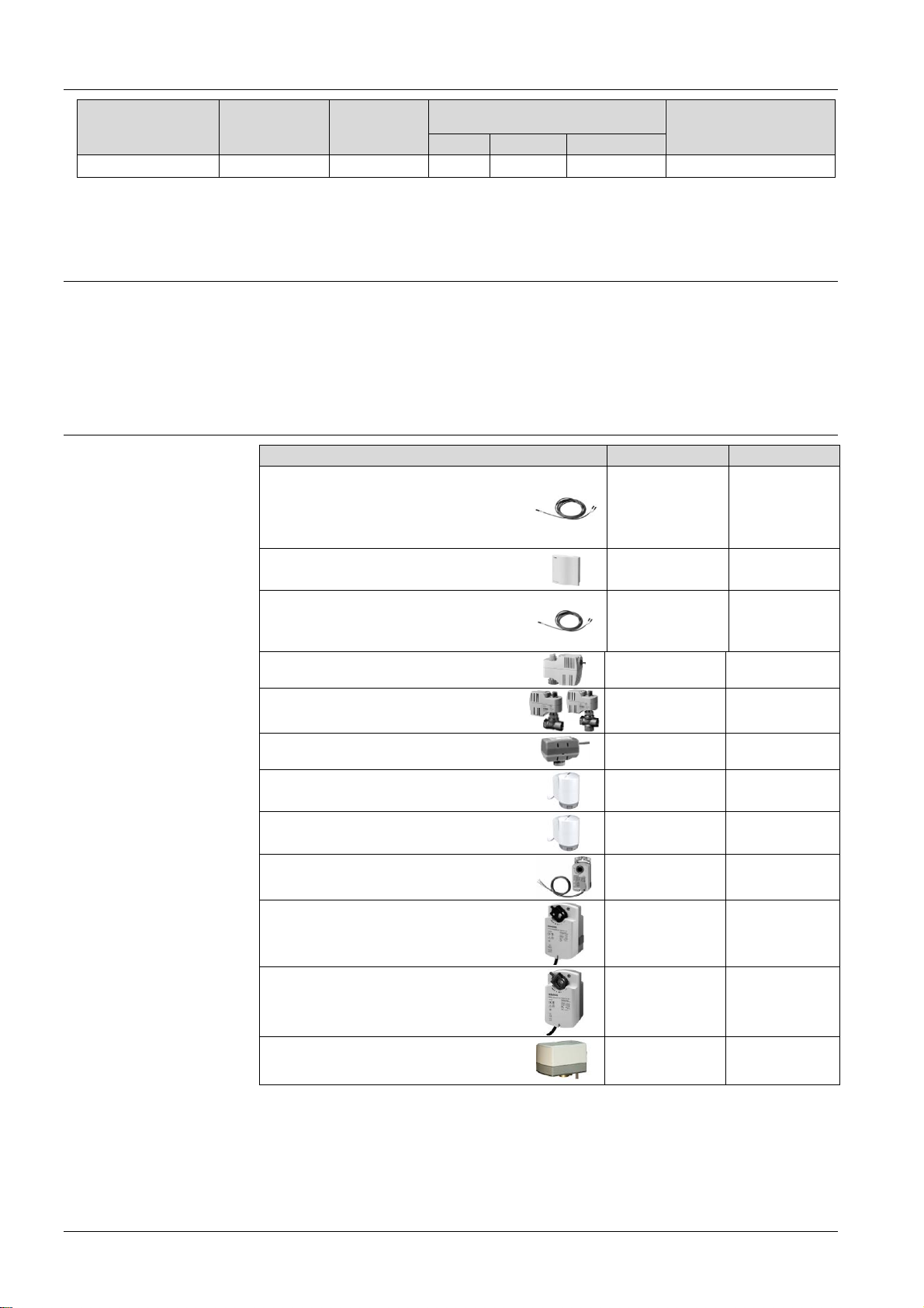
Equipment combinations
Type of unit Product no. Data sheet
Cable temperature sensor or
changeover sensor
cable length 2.5 m
NTC (3 kW at 25 °C)
Room temperature sensor
NTC (3 kW at 25 °C)
Cable temperature sensor,
cable length 4 m
NTC (3 kW at 25 °C)
Control outputs
3-pos ON/OFF DC 0..10 V
1)
1
-- Square conduit box
QAH11.1
QAA32
QAP1030/UFH
Suitable for
d)
1840
1747
1854
ON/OFF actuators
Electromotoric ON/OFF actuator
Electromotoric ON/OFF valve and
actuator
Zone valve actuators
Thermal actuator
Thermal actuator
a)
a)
b)
c)
Damper actuator
Damper actuator
Damper actuator
Rotary damper actuator
a)
only available in AP, UAE, SA and IN
b)
for radiator valve
c)
for small valves 2.5 mm
SFA21...
MVI…/MXI…
SUA…
STA23...
STP23...
GDB..
GSD..
GQD..
GXD..
4863
A6V11251892
4832
4884
4884
4634
4603
4604
4622
6 / 24
Siemens RDF880KN … A6V11282546_en--_a
Building Technologies Touch Screen Flush- mount Room Thermostats with KNX Communications 2018-04-19
Page 7

d)
both QAH11.1 and QAP1030/UFH are for floor heating applications, such as
temperature limitation controls. QAP1030/UFH has a special head and 4 m long
that is more suitable for such application.
Accessories
Note:
Refer to data sheets of the actuators for the maximum number of parallel
operation.
Designation Product no. / SSN Data sheet
Single mounting frame*), Ivory White
KNX Power supply 160 mA (Siemens BT LV)
KNX Power supply 320 mA (Siemens BT LV)
KNX Power supply 640 mA (Siemens BT LV)
*)
See the dimensions of mounting frame on page 24.
ARG800.1 /
S55770-T370
5WG1 125-1AB02
5WG1 125-1AB12
5WG1 125-1AB22
--
--
--
--
7 / 24
Siemens RDF880KN … A6V11282546_en--_a
Building Technologies Touch Screen Flush- mount Room Thermostats with KNX Communications 2018-04-19
Page 8
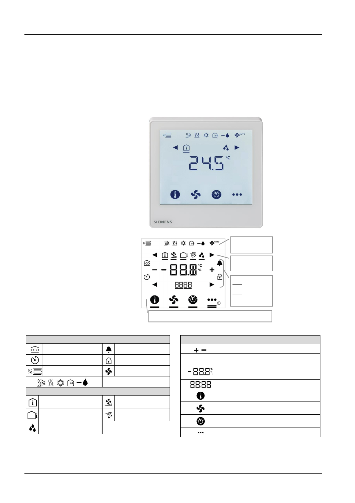
Mechanical design
INFORMATION
Operation and
settings
The thermostats consist of the following parts:
· Front panel with electronics, operating elements and built-in room temperature
and relative humidity sensors.
· Mounting base with power electronics.
· Mounting frame is an additional part to complete the installation for
RDF880KN/NF, e.g. single or multi-frames.
The rear of the mounting base contains the screw terminals.
Slide the front panel in the mounting base and snap on.
Display
Status sy mbols:
Economy active Alarm / Service active
Delay timer active Key lock active
Floor heat active Fan active
VRF operating modes
Selection symbols:
Indoor temperatur e VRF fan speed
Outdoor temperature VRF fan swing
Relative humidity
STATUS &
OPERATION of the
room thermostat
SELECTIONof
available information and
VRF fan modes
1st line: temperature or
humidity, values of
parameters
2nd line: parameters and
alarms
Both sides: STATUS
ADJUSTMENTfor temperature setpoint, fan speed, operating modes of VRF and
Floor Heating, more INFO and settings (for example, Alarm, Delay Off Timer, etc.)
Operational icons:
Increment, decrement OR selection
ƒ „
Selection OR move to next items
Temperature, relative humidity OR
parameter values, etc.
Parameters OR password, etc.
Setpoint mode (temperature only)
Fan mode OR fan speed mode
VRF & floor heat operating modes
More info & settings
8 / 24
Siemens RDF880KN … A6V11282546_en--_a
Building Technologies Touch Screen Flush- mount Room Thermostats with KNX Communications 2018-04-19
Page 9

Engineering notes
Mounting and installation
See the "Reference documentation", page 21, for information on how to engineer
the KNX bus (topology, bus repeaters, etc.) and how to select and dimension
connecting cables for supply voltage and field devices.
Mount the room thermostat on a conduit box. Do not mount on a wall in niches or
between bookshelves, behind curtains, above or near heat sources, or exposed to
direct solar radiation. Mount about 1.5 m above the floor.
Mounting / Dismounting
Wiring
· Do not apply excessive force on screws! The deformation of the mounting
frame may lead to improper connections and operation of the unit.
· Mount the room thermostat on a clean, dry indoor place without direct airflow
from a heating / cooling device, and not exposed to drips or water.
· Before removing the front cover, disconnect the power supply.
See the User Manual for the installation instructions enclosed with the thermostat.
· Comply with local regulations to wire, protection and earth the thermostat.
· The device has no internal fuse for supply lines to fan and actuators. To avoid
risk of fire and injury due to short-circuits, the AC 230 V mains supply line must
have a circuit breaker with a rated current of no more than 10 A.
· The wiring cross section used for power supply (L, N) and 230 V outputs
(Qxx - N) must be adapted to the preceding overload protection elements (max
10 A) under all circumstances. Comply under all circumstances with local
regulations.
· Properly size the cables to the thermostat and valve actuators for
AC 230 V mains voltage.
· Cables of SELV inputs X1-M / X2-M: Use cables with min 230 V insulation, as
the conduit box carries AC 230 V mains voltage.
· Inputs X1-M or X2-M of different units (e.g. window contact) may be connected
in parallel with an external switch. Consider overall maximum contact sensing
current for switch rating.
· KNX communication cables (input CE+ / CE-): Use cables with min 230 V
insulation, as the conduit box carries AC 230 V mains voltage.
· When a KNX bus power supply is connected on the line with communicating
thermostats and Synco controllers, the internal KNX power supply of the
Synco controllers must be switched off.
· No cables provided with a metal shield.
· Disconnect from supply before opening the cover.
9 / 24
Siemens RDF880KN … A6V11282546_en--_a
Building Technologies Touch Screen Flush- mount Room Thermostats with KNX Communications 2018-04-19
Page 10

Commiss ioning notes
Before power up
Select DIP switch setting is required for RDF880KN... thermostats.
COMMISSIONING: Download via ETS
1. DIP switch setting
All in OFF positions
3. Touch & hold this
icon > 5 s to enter
2. First power up
Press to turn ON
4. Ready for downloading
address & application
Programming mode
Touch “ON“ to exit
Wizard function
COMMISSIONING: Local via DIP Switches
1. Set application via
DIP switches
DIP switch
positions
1 2
ON ON VRF+FLOOR HEAT
OFF ON VRF ONLY
ON OFF FLOOR HEAT ONLY
APPLIC ATION
2. Configure basic
control parameters
via Wizard
See Configure Parameters
via Wizard in Wizard function.
After power up, the wizard function guides users to configure the basic parameters
for normal operation according to the table below.
Touch ƒ / „ to advance / return to any parameter;
Touch + / - to select any desired available values.
10 / 24
Siemens RDF880KN … A6V11282546_en--_a
Building Technologies Touch Screen Flush- mount Room Thermostats with KNX Communications 2018-04-19
Page 11

LCD display Parameter Range Factory setting
Operation Selector
1: COMF > PROT
2: COMF > ECON > PROT
1
Reset
Internal Relative
Humidity Sensor
Maximum Fan
Speed
Maximum Fan
Swing
Chinese Text
Display
End of wizard
setup
OFF: Disable
ON: Enable
1 to 7
0: no swing function
1 to 10 positions
0: Disable
1: Enable
- -
ON
3
0
0
If more details are required about parameters, refer to basic documentation
CE1P3174.
To reload factory setting for all parameters, set parameter P71 to ON. Restart the
thermostat after reset, all LCD segments flash, indicating that the reset is correct.
3 seconds later, the thermostat is ready for commissioning by qualified HVAC staff.
11 / 24
Siemens RDF880KN … A6V11282546_en--_a
Building Technologies Touch Screen Flush- mount Room Thermostats with KNX Communications 2018-04-19
Page 12

A6V11282546A0
0
Siemens
Applications
RDF880KN… thermostats are for VRF HMI and heating applications.
Configure or changing parameter settings during commissioning using one of the
following tools:
- Local HMI
- Synco ACS
- ETS4/5
Connect tool
Note:
Connect the Synco ACS or ETS tools to the KNX bus cable at any point for
commissioning:
KNX
Siemens
L
X1 M X2
N Q12
Q11 Q14
RDF880KN...
CE+ CE-
ETS
RS232
N148 /
UP146 /
UP152
ETS / ACS
OCI700
or
OCI702
ACS and ETS4/5 require an interface:
- RS232 KNX interface (such as Siemens N148 / UP146 / UP152)
- OCI700 or OCI702 USB-KNX interface
An external KNX bus power supply is required if an RDF880KN/NF is connected
directly to a tool (ACS or ETS4/5) via KNX interface.
12 / 24
Siemens RDF880KN … A6V11282546_en--_a
Building Technologies Touch Screen Flush- mount Room Thermostats with KNX Communications 2018-04-19
Page 13

Setting parameters
Service level p arameters
Name Factory setting Range Resolution
Service level
Parameter
P02 User operating mode
profile (mode button)
P05 Sensor calibration (intern,
extern)
P06 Standard temperature
display
P08 Comfort setpoint 21 °C P9 to P10 0.5 K
P09 Minimum setpoint in
Comfort mode
P10 Maximum setpoint in
Comfort mode
P11 Economy heating setpoint 15 °C OFF, 5…40 °C 0.5 K
P14 Keylock function 0 0 = Unlock
P16 Buzzer function ON = Enable OFF = Disable
P22 Internal r.h. sensor ON = Enable OFF = Disable
P23 Calibration internal r.h
sensor
P27 Operating mode settings
after power failure or reset
P28 Timer with delay Off OFF = Disable OFF = Disable (do not display Delay
P29 User level password 0000 0000 - 9999
1 = Auto - Comfort Protection
0 K -5 K…+5 K 0.5 K
0 = Room Temperature or
Relative Humidity
5 °C 5…P10
35 °C P09…40 °C
0% ±20% 1%
0 = Return to Previous
Operating Mode / User
Settings
1 = Auto - Comfort - Protection
2 = Auto - Comfort - Economy Protection
0 = Room Temperature or Relative
Humidity
1 = Setpoint for Room Temperature
0.5 K
(P10 = 40 °C max)
0.5 K
(P09 = 5 °C min)
1 = Locked
2 = Setpoint
ON = Enable
ON = Enable
0 = Return to Previous Operating
Mode / User Settings
1 = Protection Mode
1 hour
Timer Mode symbol)
ON = Enable (display Delay Timer
Mode symbol)
Note: Parameter display depends on the selected application and function.
Expert level parameters with diagnostics and test
Name Factory setting Range Resolution
Expert level
Parameter
P30 P-band / Switching
diff erential in heati ng mode
P38 Functionality of X1 0 = --- no function 0 = --- (no function)
Siemens RDF880KN … A6V11282546_en--_a
Building Technologies Touch Screen Flush- mount Room Thermostats with KNX Communications 2018-04-19
1 K 0.5…6 K 0.5 K
1 = Room temp ext / Return temp
(AI)
3 = Window open detection (DI)
6 = Fault input (DI)
7 = Monitor input [Digital]
8 = Monitor input [Temp]
13 / 24
Page 14

Name Factory setting Range Resolution
Expert level
Parameter
P39 Operating action of X1 if
digital input
0 = Normally open / Open 0 = Normally open / Open
1 = Normally closed / Close
P40 Functionality of X2 0 = --- no function 0 = --- (no function)
1 = Room temp ext / Return temp
(AI)
3 = Window open detection (DI)
6 = Fault input (DI)
7 = Monitor input [Digital]
8 = Monitor input [Temp]
P41 Operating action of X2 if
digital input
P48 Minimum output on time 2-
0 = Normally open / Open 0 = Normally open / Open
1 = Normally closed / Close
1 min. 1…20 minutes 1 min.
position control output
P49 Minimum output off time 2-
1 min. 1…20 minutes 1 min.
position control output
P51 Floor heat limit
OFF OFF, 10…50 °C 1 K
temperature
P53 Fan speed 3 = 3-speed 1 = maximum 1-speed
2 = maximum 2-speed
3 = maximum 3-speed
4 = maximum 4-speed
5 = maximum 5-speed
6 = maximum 6-speed
7 = maximum 7-speed
P54 Fan Swing Position 0 = Swing function is not
available
0 = Swing function is not available
1 = Maximum 1 Position
2 = Maximum 2 Positions
3 = Maximum 3 Positions
4 = Maximum 4 Positions
5 = Maximum 5 Positions
6 = Maximum 6 Positions
7 = Maximum 7 Positions
8 = Maximum 8 Positions
9 = Maximum 9 Positions
10 = Maximum 10 Positions
P65 Protection heating setpoint 8 °C OFF, 5…40 °C 0.5 K
P68 Prolong Comfort period 0: OFF 0: OFF
1 min
1…360 min
P69 Temporary setpoint
comfort (see also comfort
OFF = Disable OFF = Disable
ON = Enable
basic setpoint)
P71 Reload factory setting OFF = Disable OFF = Disable
ON = Reload factory setting
Reload starts only after exits
parameter mode.
P81 Device address 255 1…255 1
P82 Geographical zone
(apartment)
--(out of service)
---, 1…126 1
P83 Geographical zone (room) 1 ---, 1…63 1
14 / 24
Siemens RDF880KN … A6V11282546_en--_a
Building Technologies Touch Screen Flush- mount Room Thermostats with KNX Communications 2018-04-19
Page 15

Name Factory setting Range Resolution
Diagnostics and
Expert level
Parameter
P84 Heat distr. zone heating
coil
P88 Substitution for PreComfort
(from BUS)
P98 Chinese text display
enable
---
---, 1…31 1
(out of service)
0 = Economy 0 = Economy
1 = Comfort
0: Disable 0: Disable
1: Enable
P99 Installer Level Password 9999 5000 - 9999
Name Factory setting Range Resolution
Parameter
test
d01 Application no Diagnose 0 = --- (No application)
1 = Floor Heating only
2 = VRF only
3 = VRF and Floor Heating
d02 X1 status Diagnose
(display values according
to the selected function of
X1:
DI, AI, HC changeover,
0 = Not activated (for DI)
1 = Activated (DI)
0…49 °C = cur. temp. value (for AI)
00 = HC input short
100 = HC input open
etc)
d03 X2 status Diagnose
(display values according
to the selected function of
X2:
DI, AI, HC changeover,
0 = Not activated (for DI)
1 = Activated (DI)
0…49 °C = cur. temp. value (for AI)
00 = HC input short
100 = HC input open
etc)
d07 Software version
Show Ux.xx
d11 Floor Heating NC Output
Status (Q12)
d12 Floor Heating NO Output
Status (Q14)
Diagnose OPE = OPEN
CLO = CLOSE
Diagnose OPE = OPEN
CLO = CLOSE
Siemens RDF880KN … A6V11282546_en--_a
Building Technologies Touch Screen Flush- mount Room Thermostats with KNX Communications 2018-04-19
15 / 24
Page 16

Control parameters
KNX communications
The thermostat's control parameters can be set to ensure optimum performance of
the entire system (refer to basic documentation CE1P3174).
The parameters can be adjusted using
- Local HMI
- Synco ACS
- ETS4/5
For commissioning via local HMI, refer to user manual A6V11272225 for setting the
passwords.
Control sequence
Calibrate sensor
Setpoint and range
limitation
Programming mode
Assign KNX device
address
· Only heating sequence is available.
· Recalibrate the temperature sensor if the room temperature displayed on the
thermostat does not match the room temperature measured (after min. 1 hour of
operation). To do this, change parameter P05.
LCD display Parameter Range Factory setting
Sensor Calibration
-5…5 K
0 K
· We recommend to review heating setpoint and their range limitation via
parameters P08…P11. If necessary, adjust them to achieve maximum comfort
and save energy.
The programming mode helps identify the thermostat in the KNX network during
commissioning.
Touch and hold for more than 5 seconds to activate programming mode, which
is indicated on the display with Pr09. Programming mode remains active until
thermostat identification is complete.
Assign device address (P81) via HMI, ACS or ETS4/5.
With device address set to 255, the communication is deactivated (no exchange of
process data).
Assign KNX group
addresses
KNX serial number
S-mode
LTE mode
16 / 24
Use ETS4/5 to assign the KNX group addresses of the RDF communication
objects.
Each device has a unique KNX serial number inside the front panel. An additional
sticker with the same KNX serial number is enclosed in the packaging box. This
sticker is intended for installers for documentation purposes.
The RDF880KN… room thermostats support communications as per KNX
specification.
- S-mode: Standard mode; engineering using group addresses.
- LTE mode: Logical Tag Extended mode, for easy engineering, used in
conjunction with Synco.
· This mode corresponds to KNX communications. Connections are established
via ETS by assigning communication objects to group addresses.
· LTE mode is specifically designed to simplify engineering. In contrast to S-mode,
there is no need to create individual connections (group addresses) in the tool.
The devices establish connections autonomously.
Siemens RDF880KN … A6V11282546_en--_a
Building Technologies Touch Screen Flush- mount Room Thermostats with KNX Communications 2018-04-19
Page 17

KNX S-mode communication object
Obj. Obje ct N am e Function Type Length CRWTU
4 Fault informati on alarm info 219.001 6 bytes CT
5 Fault state faulty/normal 1.005 1 bit CT
6 Fault transmission enable/disable 1.003 1 bit CWU
Room op eratin g mode:
7
Preselection
Room op eratin g mode:
8
Preselection Auto
Room op eratin g mode:
9
Presele ction Comfort
Room op eratin g mode:
10
Preselection Economy
Room op eratin g mode:
11
Preselection Protection
Room op eratin g mode:
12
Time switch
Room op eratin g mode:
13
Time sw itch Com fort
Room op eratin g mode:
14
Time switch Economy
Room op eratin g mode:
15
Time switch Protection
Room op eratin g mode:
16
State
Room op eratin g mode:
17
State Comfort
Room op eratin g mode:
18
State Economy
Room op eratin g mode:
19
State Prote ction
Room op eratin g mode:
20
Window state
21 Room temp erature
Room temp: Comfort
22
basic setpoint
Room temp: Comfort
23
setpoint
Room temp: Current
24
setpoint
Heating output
25
primary
VRF Operating Mode:
31
State
33*)Fan operation
HVAC mode
switch 1.001 1 bit CW
switch 1.001 1 bit CW
switch 1.001 1 bit CW
switch 1.001 1 bit CW
HVAC mode
switch 1.001 1 bit CW
switch 1.001 1 bit CW
switch 1.001 1 bit CW
Comfort
Economy
Protection
switch 1.001 1 bit CT
switch 1.001 1 bit CT
switch 1.001 1 bit CT
open/c lose 1.019 1 bit CWU
temp erature
value (°C)
temp erature
value (°C)
temp erature
value (°C)
temp erature
value (°C)
percentage
(0..100% )
HVAC
control mode
switch
20.102 1 byte CWTU
20.102 1 byte CWU
20.102 1 byte CRT
9.001 2 byt es CRT
9.001 2 byt es CWU
9.001 2 byt es CWTU
9.001 2 byt es CRT
5.001 1 byte CRT
20.105 1 byte CWU
1.001 1 bit CRWTU
Descriptions / Selections:
visibility depends on DIP switch setting
CONTROL: all D IP switch Settings
It is a command to send out common ala rm output in alarm numbers/codes.
CONTROL : all DIP switch S ettings
It is a command to set the alarm flag if an alarm occ urs.
STATU S: all DIP sw itch Settings
A value (enable o r disable) is received f rom a supervisory alarm system to enable
or disable the b roadcasting of alarms by the devices. This has no impac t on the
local display of alarms. The sending of faults/alarms will be enabled automatically
after time out (48 hours).
CONTROL/STATU S: use for DIP switch Setting à 1: UFH, 3: BOTH
To change or to receive the room operating mode select ion via the bus.
Note: The thermostat will switch from Precomfort to Economy or Comfort mode
(selectable via P88).
STATUS: use fo r DIP switch Setti ng à 1: UFH, 3: BOTH
The value is received to switch the room operating mode to Auto, Comfort,
Economy or Protection.
STATUS: use fo r DIP switch Setti ng à 1: UFH, 2: VRF
A time schedule defining the required operating modes is provided by a cent ral
time switch or a supervisor.
Protection mode ha s the highest priorit y and cannot be overridden. (also refe r to
P88 - P recomfo rt à Economy or Comfort)
STATUS: use fo r DIP switch Setti ng à 1: UFH, 2: VRF
The value is received to switch the room operating mode to Auto, Comfort,
Economy or Protect ion according to a time schedule provided by a central time
switch or a sup ervisor.
CONTROL: use f or DIP switch Setting à 1: UFH, 3: BOTH
It is a command to set the operating mode to Comfort, Economy or Protection
depending on user selection, windo w contact, etc.
CONTROL: use f or DIP switch Setting à 1: UFH, 3: BOTH
it is a command to s witch the room operating mode to Comfort, Economy or
Protection.
STATUS: all DIP switch Settings
A value “1” (ope n) is received to set ope rating mode t o Protection (UFH) or Off
(VRF) i.e. UFH to Protection, VRF to Off.
A value “0” (close) is received to switch bac k to the previous operating mode
"Window state" is recei ved from a KNX control device or via the local window
contac t X1, X2 (P38, P 40).
Note: Only one input source must be used, eit her local input X 1/X2 or KNX bus.
CONTROL: all D IP switch Settings
It is a command to send out the current room temperat ure measured using builtin or external sensor (via X1 or X2).
STATUS: all DIP switch Settings
If temporary setpoint function is enabled (P69=ON), after any operating mode
changes, the setpoint will be reset to the C omfort ba sic setpoint.
Note: User setpoint via the local HMI may be overwritten du ring a system startup
from a central cont rol unit, e.g. RMB795B.
CONTROL/STATUS: all DIP switch Settings
Communication object is used to shift the setpoint for the thermostat. Same
priority as local setpoint shift on the thermostat.
Note: The Comf ort basic setpoint (objec t 22) is not changed.
CONTROL: all D IP switch Settings
It is the command to send out f or the current setpoint under c urrent operating
mode, including shift, compensation, etc., used by the thermostat for room
temp erature co ntrol.
CONTROL: use f or DIP switch Setting à 1: UFH, 3: BOTH
It is a command to send out to i ndicate the current position of the heating
actuator when UFH is act ive.
STATUS: all DIP switch Settings
The value of the V RF operating mode is set by a KNX control device.
0 - Auto; 1 - Heat ; 3 - Cool; 9 - Fan; 1 4 - Dry
CONTROL/STATU S: use for DIP switch Setting à 2: VRF
It is a command to set the current f an mode to the VRF: Auto ( 0); Manual (1).
17 / 24
Siemens RDF880KN … A6V11282546_en--_a
Building Technologies Touch Screen Flush- mount Room Thermostats with KNX Communications 2018-04-19
Page 18

Obj. Object N am e Function Type Length CRWTU
Fan speed:
35
preselection
36 Fan speed
37 Fan speed status
38 VRF Operating Mode
39 X1: Temperatu re
41 X2: Tem perature
40 X1: Digital switch 1.001 1 bit C RT
42 X2: Digital switch 1.001 1 bit C RT
43 Contr ol on/of f switch 1.001 1 bit C RT
Contr ol vane up /dow n
44
positi on
Contr ol vane up /dow n
45
swing
46 Contr ol eco mode start/stop 1.01 1 bit CRT
47 Status on/off Switch 1.00 1 1 bit CWU
Status vane up/d own
48
positi on
Status vane up/d own
49
swing
50 Sta tus ec o mode Switch 1.001 1 bit CWU
51 Room relative humidity Humidity % 9.007 2 bytes CRT
Room temp: Economy
53
heating setpoint
Application selection:
55
State
Sub application:
56
Preselection
Sub application:
57
State
C: Communication; R: Read; W: Write; T: Transmission; U: Update
Notes: The current RDF880KN/NF is based on a Floor Heating Controller with additional VRF HMI. Therefore, to turn on the controller, effectively, it is to turn on the UFH application.
1. In a UFH application selected via DIP switch setting or remote configuration, the operations are identical to RDD810KN/NF while all VRF relevant S-mode objects are invisible.
2. In a VRF application selected via DIP switch setting or remote configuration, UFH application will not be turned ON remotely via any KNX control devices or locally via HMI.
3. In a combined application (both UFH and VRF) selected via DIP switch setting or remote configuration, the object Sub Application (56, 57) can be used by any KNX control devices
to do remote selection of applications (UFH only, VRF only or UFH & VRF) required. But the objects: Time Switch/Schedule (12, 13, 14, and 15) or ECO mode (10, 18) via any KNX
control devices remotely will turn on/off both VRF and UFH. Therefore, it is not recommended to use objects: Time Switch/Schedule (12, 13, 14, and 15) or ECO mode (10, 18).
*) If object Fan operation (33) is used together with object Fan speed (36), the value “0 – Auto” of object Fan speed (36) cannot be used. If these two objects are not used together, the
value “0 – Auto“ can be used.
percentage
(0..100% )
counter pulses
(0..255)
counter pulses
(0..255)
HVAC
control mode
temp erature
value (°C)
temp erature
value (°C)
counter pulses
(0..255)
boolean 1.002 1 bit CRT
counter pulses
(0..255)
boolean 1.002 1 bit CWU
temp erature
value (°C)
counter pulses
(0..255)
counter pulses
(0..255)
counter pulses
(0..255)
5.001 1 byte CRWTU
5.010 1 byte CRT
5.010 1 byte C WU
20.105 1 byte CRT
9.001 2 byt es CRT
9.001 2 byt es CRT
5.010 1 byte CRT
5.010 1 byte C WU
9.001 2 byt es CWU
5.010 2 byt es CR
5.010 1 byte CRT
5.010 1 byte C WU
Descriptions / Selections:
visibility depends on DIP switch setting
CONTROL/STATU S: use for DIP switch Setting à 2: VRF
It is a command to set the fan speed (ECM) – d epends on value of P53.
e.g. if P53 = 3, indicates the curre nt fan speed as a value 0...100%
Speed Fan output (physical KNX value)
OFF 0% (0)
1 33% (84 )
2 66% (186)
3 100% (255)
CONTROL: use f or DIP switch Setting à 2: VRF
It is a command to set the fan speed – depe nds on value of P53.
0 – Auto; 1 - Speed 1; 2 - Speed 2; 3 - Speed 3;4 - Speed 4; 5 - Speed 5; 6 - Speed
6; 7 - Speed 7
STATUS: use fo r DIP switch Setti ng à 2: VRF
The value of fan speed received will be set and displayed on HMI.
Speed depends on va lue of P53:
0 – Auto; 1 - Speed 1; 2 - Speed 2; 3 - Speed 3;4 - Speed 4; 5 - Speed 5;
6 - Speed 6; 7 - Speed 7
CONTROL: use f or DIP switch Setting à 2: VRF
It is a command to set the VRF ope rating mode fo r VRF equipme nt.
0 - Auto; 1 - Heat ; 3 - Cool; 9 - Fan; 1 4 - Dry
CONTROL: all D IP switch Settings
Indicate the va lues of the temperature sensors connected t o the local inputs
X1/X2 ( P38/P40).
CONTROL: all D IP switch Settings
Indicates the logic state of the digital i nputs (P39 for X1, P41 for X2).
CONTROL: use f or DIP switch Setting à 2: VRF
It is a command t o turn on and off the VR F equipment.
0 - Of f; 1-On
CONTROL: use f or DIP switch Setting à 2: VRF
It is a command to set the vane position of the VRF equipment.
0 – Auto; 1 - Pos 1; 2 - Pos2; 3 - Pos3; 4 - Pos4; 5 - Pos5; 6 - Pos6; 7 - Pos7; 8 - Pos8;
9 - Pos9; 10 - P os10
CONTROL: use f or DIP switch Setting à 2: VRF
It is a command to set the vane to a stop po sition or auto swi ng.
The vane position depends on the object, Control vane up/down position ( 44).
0 - Stop; 1 – Swing
CONTROL: use f or DIP switch Setting à 2: VRF
It is a command t o enable or disable the EC O mode of the VRF equipm ent.
0 - Stop; 1 – Sta rt
STATUS: use fo r DIP switch Setti ng à 2: VRF
A value is received from a KNX control device to turn on and off t he VRF
equipment. 0 - Off; 1-On
STATUS: use fo r DIP switch Setti ng à 2: VRF
A value is received from a KNX control device to set the vane po sition of the VRF
equipment.
0 – Auto; 1 - Pos 1; 2 - Pos2; 3 - Pos3; 4 - Pos4; 5 - Pos5; 6 - Pos6; 7 - Pos7; 8 - Pos8;
9 - Pos9; 10 - P os10
STATUS: use fo r DIP switch Setti ng à 2: VRF
A value is received from a KNX control devic e to set the vane of t he VRF
equipment to stop or a uto swing. 0 - Stop; 1 – Swing
STATUS: use fo r DIP switch Setti ng à 2: VRF
A value is received from a KNX control device to set the VRF equipme nt in ECO
mode. 0 - Off; 1-On
CONTROL: all D IP switch Settings
It is the command to send out f or the current value of relative humidity.
STATUS: all DIP switch Settings
A value is received from a KNX control device to upda te parameter P11.
CONTROL : all DIP switch Settings
A value is required to be read out from RDF880KN/NF for the current DIP SW
setting. Refer to d ip switch position select ion.
1 - UFH only; 2 - VRF only; 3 - both VR F & UFH
CONTROL: use f or DIP switch Setting à 3: BOTH
It is a command to send out for the current sub selection below within a combined
UFH and VRF/VRF unit.
1 - UFH only; 2 - VRF only; 3 - both VR F & UFH
STATUS: use fo r DIP switch Setti ng à 3: BOTH
A value is received from a KNX control device f or the current sub selection below
within a combined UFH and VRF/VRF unit.
1 - UFH only; 2 - VRF only; 3 - both VR F & UFH
18 / 24
Siemens RDF880KN … A6V11282546_en--_a
Building Technologies Touch Screen Flush- mount Room Thermostats with KNX Communications 2018-04-19
Page 19

Disposal
The device is considered electrical and electronic equipment for disposal in terms of
the applicable European Directive and may not be disposed of as domestic garbage.
· Dispose of the device through channels provided for this purpose.
· Comply with all local and currently applicable laws and regulations.
19 / 24
Siemens RDF880KN … A6V11282546_en--_a
Building Technologies Touch Screen Flush- mount Room Thermostats with KNX Communications 2018-04-19
Page 20

Technical data
Power supply
Rated voltage AC 230 V
Overvoltage category III
Frequency 50/60 Hz
Power consumption Max. 6.0 VA / 2.1 W
Caution
No internal fuse.
External preliminary protection with max C 10 A circuit breaker required in all cases.
Outputs Control output Q11, Q12, Q14 (SPDT)
Rating Min, Max resistive (inductive)
Caution
No internal fuse.
External preliminary protection with max C 10 A circuit breakers in the supply line
(Q11) required in all cases.
Inputs Multifunctional input X1-M/X2-M
Temperature sensor input:
Type
Temperature range
Cable length
Digital input:
Operating action
Contact sensing
Parallel connection of several thermostats
for one switch
Insulation against mains voltage (SELV)
AC 24…230 V
Min. 10 mA, Max. 5(2) A
See “Equipment combinations”
0...49 °C
Max. 80 m
Selectable (NO / NC)
SELV DC 0...5 V / Max. 5 mA
Max. 20 thermostats per
switch
4 kV, reinforced insulation
Function of inputs:
External temperature sensor, window contact, fault
contact, monitoring input
Selectable
X1: P38
X2: P40
KNX bus Interface type KNX, TP1-64
(electrically isolated)
Bus current 5 mA
Bus topology: See KNX manual (Reference documentation, see below)
Operational data Switching differential, adjustable
Heating mode (P30) 1 K (0.5...6 K)
Setpoint setting and range
Comfort (P08)
Economy (P11)
Protection (P65)
Multifunctional input X1/X2
Input X1 default value (P38)
Input X2 default value (P40)
21 °C (5...40 °C)
15 °C (OFF, 5...40 °C)
8 °C (OFF, 5...40 °C)
Selectable 0, 1, 3, 6, 7, 8
0 (no function)
0 (no function)
Built-in room temperature sensor
Measuring range
Accuracy at 25 °C
Temperature calibration range
0…49 °C
< ± 0.5 K
± 5.0 K
Settings and display resolution
Setpoints
Current temperature value displayed
0.5 °C
0.5 °C
Built-in room humidity sensor
Measuring range
Accuracy at 25 °C
Humidity calibration range
0…100%
± 5% r.h.
± 20%
Settings and display resolution
Display resolution
1% r.h.
20 / 24
Siemens RDF880KN … A6V11282546_en--_a
Building Technologies Touch Screen Flush- mount Room Thermostats with KNX Communications 2018-04-19
Page 21

Environmental
2
conditions
Operation
Climatic conditions
Temperature
Humidity
Transport
Climatic conditions
Temperature
Humidity
Mechanical conditions
Storage
Climatic conditions
Temperature
Humidity
As per IEC 60721-3-3
Class 3K5
0...50 °C
<95 % r.h.
As per IEC 60721-3-2
Class 2K3
-25... 65 °C
<95 % r.h.
Class 2M2
As per IEC 60721-3-1
Class 1K3
-25...65 °C
<95 % r.h.
Standards and
directives
EU Conformity (CE) A6V11350285
Electronic control type 2.B (micro-disconnection on
*)
operation)
RCM conformity to EMC emission standard
A6V11350287
Safety class II as per EN 60730
Pollution class Normal
Degree of protection of housing IP 30 as per EN 60529
Environmental
compatibility
The product environmental declaration E3174en contains data on environmentally
compatible product design and assessments (RoHS compliance, materials
composition, packaging, environmental benefit, disposal).
Eco design and
labelling directives
Based on EU Regulation 813/2013 (Eco design directive) and 811/2013 (Labelling
directive) concerning space heaters, combination heaters, the following class apply:
- Application with On/Off operation of a heater
Class I value 1%
General Connection terminals Solid wires or prepared
stranded wires
1 x 0.4…1.5 mm2 or
2 x for KNX cables/sensor
Minimal wiring cross section on L, N, Qxx Min 1.5 mm
Housing front color Ivory White
Weight without / with packaging 0.145 kg / 0.245 kg
*)
The documents can be downloaded from http://siemens.com/bt/download.
Reference
documentation
Handbook for Home and Building Control - Basic Principles
(http://www.knx.org/knx-en/training/books-documentation/knx-association-books/index.php)
Synco CE1P3127 Communication via the KNX bus for Synco 700, 900 and RXB/RXL
Basic documentation
Desigo CM1Y9775 Desigo RXB integration – S-mode
CM1Y9776 Desigo RXB / RXL integration – individual addressing
CM1Y9777 Third-party integration
CM1Y9778 Synco integration
CM1Y9779 Working with ETS
21 / 24
Siemens RDF880KN … A6V11282546_en--_a
Building Technologies Touch Screen Flush- mount Room Thermostats with KNX Communications 2018-04-19
Page 22

Connection terminals
3171A01
-
3171A12
L X1M
N
SELV
Q11 Q14 Q12
X2
Connec tion diagr a m s
CE+ CE
L, N Operating voltage AC 230 V
Q11, Q12 NC contact (for NO valves)
Q11, Q14 NO contact (for NC valves)
X1, X2 Multifunctional input for temperature sensor or potential-
free switch
Factory setting:
– X1 = Window contact
– X2 = External sensor
(function can be selected via parameter P38 / P40)
M Measuring neutral for sensor and switch
CE+ KNX data +
CE- KNX data -
L
10 A
S1
B1
S2
B2
KNX
N1 Room thermostat
V1 Valve actuator
Lx AC 24...230 V
S1, S2 Switch (keycard, window contact, presence detector,
etc.)
L
X1
X2
M
CE+ CE-
B1, B2 Temperature sensor (return air temperature,
external room temperature, changeover sensor, etc.)
Q11 Q 14 Q12
N
AC 230 V
10 A
5(2)A
V1
Lx
N
Max.
N1
CE+ KNX data +
CE- KNX data –
22 / 24
Siemens RDF880KN … A6V11282546_en--_a
Building Technologies Touch Screen Flush- mount Room Thermostats with KNX Communications 2018-04-19
Page 23

Dimensions (mm)
RDF880KN/NF
for square conduit
boxes on ly
23 / 24
Siemens RDF880KN … A6V11282546_en--_a
Building Technologies Touch Screen Flush- mount Room Thermostats with KNX Communications 2018-04-19
Page 24

www.siemens.com/buildingtechnologies
ARG800.1 single
mounting frame for
RDF880KN/NF
Issued by
Siemens Switzerland Ltd.
Building Technologies Division
International Headquarters
Theilerstrasse 1a
CH-6300 Zug
Tel. +41 58 724 2424
24 / 24
Siemens RDF880KN … A6V11282546_en--_a
Building Technologies Touch Screen Flush- mount Room Thermostats with KNX Communications 2018-04-19
Technical speci fic ati ons and availabi lit y su bjec t to chan ge with out n otice.
© Siemens Switzerland Ltd., 2018
 Loading...